JP3980498B2 - Lifter magnet - Google Patents
Lifter magnet Download PDFInfo
- Publication number
- JP3980498B2 JP3980498B2 JP2003049274A JP2003049274A JP3980498B2 JP 3980498 B2 JP3980498 B2 JP 3980498B2 JP 2003049274 A JP2003049274 A JP 2003049274A JP 2003049274 A JP2003049274 A JP 2003049274A JP 3980498 B2 JP3980498 B2 JP 3980498B2
- Authority
- JP
- Japan
- Prior art keywords
- movable
- main pole
- movable yoke
- pole
- workpiece
- Prior art date
- Legal status (The legal status is an assumption and is not a legal conclusion. Google has not performed a legal analysis and makes no representation as to the accuracy of the status listed.)
- Expired - Lifetime
Links
Images


Landscapes
- Load-Engaging Elements For Cranes (AREA)
Description
【0001】
【発明の属する技術分野】
本発明は、複数の可動ヨークを備えて異形のワークを吸着可能なリフタマグネットに関する。
【0002】
【従来の技術】
一般に、ワークを、例えば、ワークストッカから加工装置に搬送する場合、ロボット等でワークを把持して搬送することが行われている。しかし、加工装置に搬送されるワークは、必ずしも把持面が平面状に形成されているとは限らず、湾曲面や凹凸状の段差面等を含んだ異形状に形成されたものがある。これらのワークを搬送する場合には、ロボットのハンドでは把持できないことから、特許文献1に示すようなワークの面に倣って移動して吸着する複数の可動ヨークを備えたリフタマグネットが使用されていた。
【0003】
この特許文献1に示されているリフタマグネット21は、図11に示すように、主極23と補助極25とが並設して配置され、主極23に巻装されるコイル24と、主極23の両側面に主極23に対して移動可能な複数の可動ヨーク26とを備えて構成されていた。そして可動ヨークの26先端部がそれぞれ異形のワークWの表面に接触すると、コイル24を励磁することによって主極23・可動ヨーク26・ワークWに磁気回路C12を形成してワークWを磁力で吸着するとともに、主極23・可動ヨーク26・補助極25に磁気回路C13を形成して可動ヨーク26を強固に保持するように構成していた。
【0004】
【特許文献1】
特許第3338953号公報(2〜4頁、図1)
【0005】
【発明が解決しようとする課題】
しかし、ワークWの表面が平面上でX方向・Y方向の広い範囲にわたって湾曲面や凹凸状の段差面を形成しているものにおいては、可動ヨーク26が主極23を挟んで1列に配置されている従来のリフタマグネット21では、可動ヨーク26の長手方向に並設されたX方向においては複数の可動ヨーク26でワークWの湾曲面に倣って吸着できるものの、可動ヨーク26の並設された方向に対して直交するY方向には、ワークWの湾曲面に倣って充分に吸着することができない。従ってリフタマグネット21で吸着する保持力が低下してワークWをリフタマグネット21から脱落させてしまう虞れが生じていた。
【0006】
本発明は、上述の課題を解決するものであり、広い範囲にわたって湾曲面が形成されていたりあるいは凹凸状の段差面を有して形成されたりするワークを、強固な保持力で吸着できるリフタマグネットを提供することを目的とする。
【0007】
【課題を解決するための手段】
本発明に係るリフタマグネットは、上記の課題を解決するために、以下のように構成するものである。すなわち、
本発明では、枠体内に支持される主極と、前記主極の周りに巻装されるコイルと、前記主極の両側面で前記主極に対して移動可能に配置される可動ヨークとを備え、前記主極・前記可動ヨーク・ワークの間で磁気回路を形成して前記ワークを吸着可能なリフタマグネットであって、
前記可動ヨークが、前記主極の両側面において重合方向に多数列に配置され、
前記主極に並設して補助極が前記枠体に支持され、前記主極・前記可動ヨーク・前記補助極の間に磁気回路が形成され、
多数列に配置された各列の可動ヨーク間のうち、前記主極側の可動ヨークには非磁性部が配設されていることを特徴とするものである。
【0010】
さらに、本発明では、前記主極側の可動ヨークに配設された非磁性部は、前記主極側の可動ヨークの移動時に、前記主極と前記補助極間の範囲内で移動可能に配置されていることを特徴としている。
【0011】
また、本発明では、枠体内に支持される主極と、前記主極の周りに巻装されるコイルと、前記主極の両側面で前記主極に対して移動可能に配置される可動ヨークとを備え、前記主極・前記可動ヨーク・ワークの間で磁気回路を形成して前記ワークを吸着可能なリフタマグネットであって、
前記可動ヨークが、前記主極の両側面において重合方向に多数列に配置され、
前記主極に並設して補助極が前記枠体に支持され、前記主極・前記可動ヨーク・前記補助極の間に磁気回路が形成され、
多数列に配置された各列の可動ヨークは、前記主極と一体的に形成された磁性体のガイド枠で支持されるとともに、前記補助極と一体的に形成された磁性体のガイド枠で支持され、各列の可動ヨーク間には、非磁性体のスペーサが介在されていることを特徴とするものである。
【0012】
【発明の効果】
本発明によれば、リフタマグネットの可動ヨークが主極を挟んで重合する方向に多数列に配置されていることから、ワークの直交する2方向に対して可動ヨークをワークの湾曲面あるいは凹凸面に対して倣うことができ、強固な吸着力でワークを保持することができる。
【0013】
つまり、リフタマグネットをワークに対向して載置すると、主極に隣接する第1列目の可動ヨーク列においては、可動ヨークの先端部がワークの1方向に対する湾曲面あるいは凹凸面に倣って接触することによって、ワークの凹凸面の状態により各可動ヨークが主極に対してそれぞれ上昇して停止する。この位置でコイルを励磁すると、主極・第1列目の可動ヨーク・ワークに磁束が流れて磁気回路を形成し、それによってワークが第1列目の可動ヨーク列の磁力で吸着される。
【0014】
一方、第2列目の可動ヨーク列においては、各可動ヨークの先端部がワークの1方向に対する湾曲面あるいは凹凸面に倣って接触することによって、ワークの凹凸面の状態により各可動ヨークが主極に対してそれぞれ上昇して停止する。この位置でコイルを励磁すると、主極・第2列目の可動ヨーク・ワークに磁束が流れて磁気回路を形成し、それによってワークが第2列目の可動ヨーク列の磁力で吸着される。
【0015】
従って、各可動ヨークを主極の長手方向に沿って並設するとともに、第2列、第3列、…第N列と可動ヨーク列を重合するように配置すれば、可動ヨーク列の並設された方向と直交する方向に可動ヨークを配置することができることから、直交する2方向にわたってワークを吸着することができて異形ワークの吸着力を向上させることができる。
【0016】
本発明によれば、ワーク湾曲面あるいは凹凸面に倣って接触した各可動ヨークがコイルの励磁により、主極・可動ヨーク・ワーク間に磁気回路が形成されてワークを吸着するとともに、主極・可動ヨーク・補助極間にも磁束が流れて磁気回路を形成することとなることから、ワークの異形面に倣って上方に移動した可動ヨークをワーク吸着状態で保持することができる。従って、可動ヨークを強固に保持して可動ヨークからワークの脱落を防止できる。
【0017】
本発明によれば、多数列に配置された可動ヨーク列のうち、主極側に配置する内側の可動ヨーク列の可動ヨークには、非磁性部が配設されていることから、非磁性部が配設された可動ヨーク列の次の可動ヨーク列の各可動ヨークは、非磁性部が配設された可動ヨークの非磁性部を避けて非磁性部が配設されていない外側の可動ヨークを通る磁気回路が形成されることとなり、外側の可動ヨークが内側の可動ヨークに吸着して保持されることとなる。
【0018】
また、本発明によれば、前記可動ヨークの非磁性部は、主極と補助極との間を移動するように配置されていることから、主極・可動ヨーク・補助極を通る磁気回路は、非磁性部の外回りで形成されることとなって、外側列の可動ヨークを通ることとなる。従って主極側に配置された内側列の可動ヨークに外側列の可動ヨークを吸着させることとなって、外側列の可動ヨークにおける内側列の可動ヨークからのずれ落ちを防止することができる。
【0019】
さらに本発明によれば、各列の可動ヨークは磁性体のガイド枠で支持されるとともに、各可動ヨーク列間に非磁性体のスペーサを介在すれば、内側の可動ヨークと外側の可動ヨークとが磁気的に短絡することがないことから、磁気回路は、一方で主極・ガイド枠・内側の可動ヨーク・ワーク及び他方で主極・ガイド枠・外側の可動ヨーク・ワークと各列の可動ヨークが独立して形成できて吸着力を増加させることができる。
【0020】
【発明の実施の形態】
以下、本発明の一実施形態を図面に基づいて説明する。
【0021】
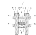
実施形態における第1の形態のリフタマグネット1は、図1〜2に示すように、四隅に立設された非磁性体の縦支柱2aと縦支柱2aを連結する2段に配置された非磁性体の横支柱2bとを備えて枠状に構成する枠体2と、枠体2内に支持される磁性体の主極3と、主極3の周りに巻装されるコイル4と、コイル4の上方で主極3と並設するように枠体2に支持される磁性体の補助極5と、主極3の長手方向に沿って主極の両側面に、主極3と横支柱2bとの間に2列に配置されて上下方向に移動可能な複数の磁性体の可動ヨーク6・7とを有して構成されている。コイル4の下面側には底板となる非磁性体のカバー8が配置されて枠体2を構成している。
【0022】
主極3に隣接する第1列目の可動ヨーク6は、上端部で補助極5の上面に当接して落下防止となるガイド61を装着し、横支柱2bに隣接する第2列目の可動ヨーク7は、上段の横支柱2bの上面に当接して落下防止となるガイド71を装着し、いずれの可動ヨーク6・7の下端部は湾曲状に形成されてワークの湾曲面あるいは凹凸面のどの位置でも接触できるように形成されている。
【0023】
2段に配置された横支柱2bは、可動ヨーク6・7の移動ガイドとして主極3及び補助極5とともに可動ヨーク6・7を挟むように配置されるとともに、可動ヨーク6・7が上下方向に移動できるように、主極3と横支柱2bとの間、および補助極5と横支柱2bとの間の隙間は、2列の可動ヨーク6・7との間で緩やかな嵌合状態を形成している。
【0024】
上記のように構成されたリフタマグネット1は、ワークに載置されていない状態では、各可動ヨーク6・7は、すべて自重により、主極3に対して下方に落下移動している。そして可動ヨーク6のガイド61が補助極5の上面で当接され、可動ヨーク7のガイド71が上段の横支柱2bの上面に当接して、それぞれ脱落防止としている。
【0025】
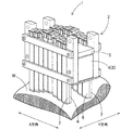
図3に示すように、X方向・Y方向に凹凸面が形成された湾曲状の異形ワークWを吸着して搬送する際、リフタマグネット1を異形ワーク上に載置すると、主極3に対して最下方位置にある可動ヨーク6及び可動ヨーク7が、ワークWの凹凸状の上面に倣って、主極3に対して上方に移動する。
【0026】
つまり、可動ヨーク6・7は、下端部がワークWの上面に倣ってそれぞれ接触するから、それぞれの可動ヨーク6・7は主極3に対して上方に移動してワークWの上面に倣ったランダムな位置で停止することとなる。図3に示すワークWのX方向に対しては、第1列目の可動ヨーク6及び第2列目の可動ヨーク7が主極3の長手方向に沿って順に並設して配置されていることから、可動ヨーク6・7の下端部がワークWの異形面に多数接触している。また、ワークWのY方向に対しては、第1列目の可動ヨーク6と第2列目の可動ヨーク7との下端部がワークWの異形面に接触することになるからワークWに対して広い範囲で当接することとなる。
【0027】
この状態で、コイル4を励磁すると、図4に示すように、第1列目の可動ヨーク6に対しては、主極3・可動ヨーク6・ワークWに磁束が流れて磁気回路C1が形成され、さらに主極3・可動ヨーク6・補助極5に磁束が流れて磁気回路C2が形成される。これによって、複数の可動ヨーク6でワークWを吸着するとともに、補助極5側に形成される磁気回路C2によって、可動ヨーク6はその位置において保持されることとなる。
【0028】
また、第2列目の可動ヨーク7に対しては、主極3・可動ヨーク7・ワークWに磁束が流れて磁気回路C3が形成され、さらに主極3・可動ヨーク7・補助極5に磁束が流れて磁気回路C4が形成される。これによって、複数の可動ヨーク7でワークWを吸着するとともに、可動ヨーク7は補助極5側に形成される磁気回路C4によってその位置において保持されることとなる。
【0029】
なお、ワークWを吸着したリフタマグネット1は、図示しないロボットのハンドに枠体2を懸吊されて、ワークストッカから図示しない加工装置に搬送されることとなる。
【0030】
上記のように、実施形態のリフタマグネット1では、可動ヨーク6・7を重合する方向に第1列目可動ヨーク列・第2列目可動ヨーク列を配置することから、ワークWに対してX方向・Y方向とも広い範囲で可動ヨークをワークWの異形表面に接触して吸着することができ、ワークWの吸着力を向上することができる。
【0031】
なお、上記形態のリフタマグネットにおいては、可動ヨーク列は、可動ヨークの重合する方向に2列で説明したものであるが、勿論、第3列目、第4列目、…第N列目以降を配置するようにしてもよい。
【0032】
次に、上記のリフタマグネット1を基本にした第2の形態について説明する。
【0033】
図5に示すように、リフタマグネット1Aの可動ヨーク6A・7Aは、主極3の両側面においてそれぞれ2列に重合するように配置されている。主極3側に配置されている可動ヨーク6Aには、長さ方向の一箇所に非磁性部63が磁性部62・62間に配置されている。
【0034】
磁性部62・62と非磁性部63は、例えば、溶接によって一体的に接合して1個の可動ヨーク6Aとして形成される。この非磁性部63の可動ヨーク6Aにおける装着位置は、図6に示すように、リフタマグネット1AをワークWの上面に載置させて、可動ヨーク6Aの下端面がワークWに接触して可動ヨーク6Aが主極3に対して上方に移動する際、非磁性部63が、主極3と補助極5との間に常に位置できるように配置する。
【0035】
これによって、図6に示すように、コイル4が励磁されて主極3・補助極5を通る磁束は、可動ヨーク6Aの非磁性部63を通ることができないことから、主極3から内側の可動ヨーク6Aにおける非磁性部63の下方に配置された磁性部62を横切って外側の可動ヨーク7Aを通り、可動ヨーク6Aにおける非磁性部63の上方に配置された磁性部62を横切って補助極5を通る磁気回路C5が形成されることとなる。従って、可動ヨーク7Aが可動ヨーク6Aに吸着されることとなって、可動ヨーク7Aの可動ヨーク6Aからの脱落を防止することとなる。
【0036】
なお、可動ヨーク6Aの下部側では、主極3・可動ヨーク6A・ワークWに磁束が流れて磁気回路C6が形成され、可動ヨーク7Aの下部側では、主極3・可動ヨーク7A・ワークWに磁束が流れて磁気回路C7が形成され、可動ヨーク6A・可動ヨーク7AでワークWを吸着保持することとなる。
【0037】
次に、第3の形態によるリフタマグネット1Bについて説明する。
【0038】
この形態においては、第1の形態で説明した枠体2を構成する横支柱2bを変更してガイド枠11・13を設ける。つまり、図7及び図8に示すように、可動ヨーク6・7を支持する上段のガイド枠11は、磁性体で形成されるとともに補助極5を挟んで両側に可動ヨーク6・7を挿通するための開口部を有するガイド部12・12を補助極5と一体的に形成する。そして開口部の中央に非磁性材のスリット壁12cを仕切るように配置してスリット壁12cの両側に長溝12a・12bを形成する。そして長溝12aに可動ヨーク6を挿通し、長溝12bに可動ヨーク7を挿通する。
【0039】
一方、図7及び図9に示すように、可動ヨーク6・7を支持する下段のガイド枠13は、磁性体で形成されるとともに主極3を挟んで両側に可動ヨーク6・7を挿通するための開口部を有するガイド部14・14を主極3と一体的に形成する。そして開口部の中央に非磁性材のスリット壁14cを仕切るように配置してスリット壁14cの両側に長溝14a・14bを形成する。そして長溝14aに可動ヨーク6を挿通し、長溝14bに可動ヨーク7を挿通することとなる。
【0040】
このガイド枠11・13を4本の縦支柱2aに支持して、主極3の下面側に非磁性体のカバー8を装着し、ガイド枠11・13の各長溝12a・12b、14a・14bにそれぞれ可動ヨーク6・7を挿通させてリフタマグネット1Bを構成する。
【0041】
このように構成されたリフタマグネット1BをワークW上に載置すると、各可動ヨーク6・7は、ワークWの凹凸面に倣って主極3に対してそれぞれ上昇する。そして、各可動ヨーク6・7がそれぞれの位置で停止すると、コイル4を励磁して磁気回路を形成する。
【0042】
この際、形成される磁気回路は、図7に示すように、内側列の可動ヨーク6では、主極3・可動ヨーク6・ワークWに磁束が流れて磁気回路C8が形成され、主極3・可動ヨーク6・補助極5に磁束が流れて磁気回路C9が形成されることとなる。
【0043】
また、外側列の可動ヨーク7の下部側では、図7及び図10に示すように、主極3から流れる磁束は、可動ヨーク6と可動ヨーク7との間に非磁性体のスリット壁14cが配置されていることから、可動ヨーク6を通って可動ヨーク7には到達できず、磁性体のガイド枠13の外周縁部を回って可動ヨーク7に流れてワークWを通るように磁気回路C10が形成されることとなる。
【0044】
さらに、外側列の可動ヨーク7の上部側では、可動ヨーク6と可動ヨーク7との間には非磁性体のスリット壁12cが配置されていることから、主極3から流れる磁束は、可動ヨーク6を通って可動ヨーク7には到達できず、磁性体のガイド枠11の外周縁部を回って可動ヨーク7に流れて補助極5を通るように磁気回路C11が形成されることとなる。
【0045】
従って、この形態においても、可動ヨーク6・7は独立して磁気回路を形成してワークWを吸着保持することができることから、ワークWのX方向とY方向との広い範囲でワークWを吸着することができて、脱落することなく加工装置側に搬送することができる。しかも、可動ヨーク6及び可動ヨーク7は、補助極5で吸着保持できることから、可動ヨーク6・7の主極3又は補助極5からのずれ落ちも防止できる。
【0046】
なお、この形態においても、ガイド枠11・13を各可動ヨーク列に配置し、隣接する列の可動ヨークと接触することがないよう、非磁性材のスリット壁を配置させて、可動ヨークをそれぞれ独立して磁気回路が形成できるようにすることで、可動ヨークをさらに多列にすることができる。
【図面の簡単な説明】
【図1】本発明の一形態によるリフタマグネットを示す全体斜視図である。
【図2】図1におけるリフタマグネットの要部を示す要部断面図である。
【図3】図1におけるリフタマグネットでワークを吸着する作用を示す斜視図である。
【図4】図1におけるリフタマグネットに形成される磁気回路を示す断面図である。
【図5】第2の形態のリフタマグネットを示す要部断面図である。
【図6】図5におけるリフタマグネットの作用を示す要部断面図である。
【図7】第3の形態のリフタマグネットを示す要部断面図である。
【図8】図7におけるリフタマグネットの上段のガイド枠を示す斜視図である。
【図9】図7におけるリフタマグネットの下段のガイド枠を示す斜視図である。
【図10】図7におけるリフタマグネットの磁気回路を示す平面断面図である。
【図11】従来のリフタマグネットを示す要部断面図である。
【符号の説明】
1、1A、1B リフタマグネット
2 枠体
2b 横支柱
3 主極
4 コイル
5 補助極
6、7 可動ヨーク
63 非磁性部
11、13 ガイド枠
12c、14c スリット壁
C1〜C11 磁気回路[0001]
BACKGROUND OF THE INVENTION
The present invention relates to a lifter magnet having a plurality of movable yokes and capable of attracting a deformed workpiece.
[0002]
[Prior art]
Generally, when a work is transported from a work stocker to a processing apparatus, for example, the work is gripped and transported by a robot or the like. However, the workpiece conveyed to the processing apparatus does not necessarily have a flat grip surface, and may be formed in a different shape including a curved surface, an uneven step surface, and the like. When transporting these workpieces, a lifter magnet provided with a plurality of movable yokes that move and adhere to the surface of the workpiece as shown in
[0003]
As shown in FIG. 11, the
[0004]
[Patent Document 1]
Japanese Patent No. 3338953 (page 2-4, FIG. 1)
[0005]
[Problems to be solved by the invention]
However, in the case where the surface of the workpiece W forms a curved surface or an uneven step surface over a wide range in the X and Y directions on the plane, the
[0006]
The present invention solves the above-mentioned problems, and is a lifter magnet that can adsorb a work having a curved surface over a wide range or having a stepped surface having an uneven shape with a strong holding force. The purpose is to provide.
[0007]
[Means for Solving the Problems]
The lifter magnet according to the present invention is configured as follows in order to solve the above problems. That is,
In the present invention, a main pole supported in a frame, a coil wound around the main pole, and a movable yoke arranged to be movable with respect to the main pole on both side surfaces of the main pole. A lifter magnet capable of adsorbing the work by forming a magnetic circuit between the main pole, the movable yoke and the work,
The movable yokes are arranged in multiple rows in the overlapping direction on both side surfaces of the main pole ,
An auxiliary pole is supported by the frame body in parallel with the main pole, and a magnetic circuit is formed between the main pole, the movable yoke, and the auxiliary pole,
Of the movable yokes in each row arranged in multiple rows, the movable yoke on the main pole side is provided with a non-magnetic portion .
[0010]
Furthermore, in the present invention, the main pole magnetic portion disposed on the movable yoke, upon movement of the movable yoke of the main electrode side, movably disposed within between the auxiliary electrode and the main electrode It is characterized by being.
[0011]
In the present invention, the main pole supported in the frame, the coil wound around the main pole, and the movable yoke arranged to be movable relative to the main pole on both side surfaces of the main pole. A lifter magnet capable of adsorbing the work by forming a magnetic circuit between the main pole, the movable yoke and the work,
The movable yokes are arranged in multiple rows in the overlapping direction on both side surfaces of the main pole,
An auxiliary pole is supported by the frame body in parallel with the main pole, and a magnetic circuit is formed between the main pole, the movable yoke, and the auxiliary pole,
The movable yokes of each row arranged in multiple rows are supported by a magnetic guide frame formed integrally with the main pole, and by a magnetic guide frame formed integrally with the auxiliary pole. A non-magnetic spacer is interposed between the movable yokes of each row supported.
[0012]
【The invention's effect】
According to the present invention, since the movable yokes of the lifter magnet are arranged in multiple rows in the direction of overlapping with the main pole interposed therebetween, the movable yokes are curved or uneven surfaces of the workpiece with respect to the two orthogonal directions of the workpiece. The workpiece can be held with a strong suction force.
[0013]
In other words, when the lifter magnet is placed facing the workpiece, in the first movable yoke row adjacent to the main pole, the tip of the movable yoke contacts the curved surface or uneven surface in one direction of the workpiece. By doing so, each movable yoke rises with respect to the main pole and stops depending on the state of the uneven surface of the workpiece. When the coil is excited at this position, magnetic flux flows through the main pole and the first row of movable yokes and workpieces to form a magnetic circuit, whereby the workpiece is attracted by the magnetic force of the first row of movable yoke rows.
[0014]
On the other hand, in the second movable yoke row, the tip of each movable yoke comes in contact with the curved surface or the concavo-convex surface with respect to one direction of the workpiece, so that each movable yoke has a main surface depending on the state of the concavo-convex surface of the workpiece. Ascend to the poles and stop. When the coil is excited at this position, magnetic flux flows through the main pole and the second row of movable yokes and workpieces to form a magnetic circuit, whereby the workpiece is attracted by the magnetic force of the second row of movable yoke rows.
[0015]
Therefore, if the movable yokes are arranged side by side along the longitudinal direction of the main pole, and the second row, the third row,... Since the movable yoke can be arranged in a direction perpendicular to the formed direction, the workpiece can be adsorbed in two directions orthogonal to each other, and the adsorption force of the deformed workpiece can be improved.
[0016]
According to the present invention, each movable yoke that is in contact with the workpiece curved surface or the uneven surface is excited by the coil, so that a magnetic circuit is formed between the main pole, the movable yoke, and the workpiece to attract the workpiece. Since the magnetic flux also flows between the movable yoke and the auxiliary pole to form a magnetic circuit, the movable yoke moved upward along the deformed surface of the workpiece can be held in the workpiece attracted state. Therefore, the movable yoke can be firmly held and the workpiece can be prevented from falling off the movable yoke.
[0017]
According to the present invention, among the movable yoke rows arranged in multiple rows, the non-magnetic portion is arranged in the movable yoke of the inner movable yoke row arranged on the main pole side. Each movable yoke in the movable yoke row next to the movable yoke row in which the non-magnetic portion is disposed avoids the non-magnetic portion of the movable yoke in which the non-magnetic portion is disposed and the non-magnetic portion is not disposed. Thus, the outer movable yoke is attracted and held by the inner movable yoke.
[0018]
Further, according to the present invention, the non-magnetic portion of the movable yoke, since it is arranged so as to move between the main pole and the auxiliary pole, a magnetic circuit through the main pole, the movable yoke auxiliary poles It is formed around the nonmagnetic portion and passes through the movable yoke in the outer row. Therefore, the movable yokes in the outer row are attracted to the movable yokes in the inner row arranged on the main pole side, thereby preventing the outer rows of movable yokes from being displaced from the movable yokes in the inner row.
[0019]
Further, according to the present invention, the movable yokes in each row are supported by the magnetic guide frame, and if a non-magnetic spacer is interposed between the movable yoke rows, the inner movable yoke and the outer movable yoke are provided. Since there is no magnetic short circuit, the magnetic circuit is movable on the main pole, guide frame, inner movable yoke and workpiece on the one hand, and on the other side, the main pole, guide frame, outer movable yoke and workpiece and movable on each row. The yoke can be formed independently and the attractive force can be increased.
[0020]
DETAILED DESCRIPTION OF THE INVENTION
Hereinafter, an embodiment of the present invention will be described with reference to the drawings.
[0021]
As shown in FIGS. 1 and 2, the
[0022]
The
[0023]
The
[0024]
In the state where the
[0025]
As shown in FIG. 3, when the
[0026]
In other words, since the
[0027]
When the
[0028]
Further, with respect to the
[0029]
The
[0030]
As described above, in the
[0031]
In the lifter magnet of the above embodiment, the movable yoke rows are described in two rows in the direction in which the movable yokes overlap. Of course, the third row, the fourth row,... May be arranged.
[0032]
Next, a second embodiment based on the
[0033]
As shown in FIG. 5, the
[0034]
The
[0035]
As a result, as shown in FIG. 6, the magnetic flux passing through the
[0036]
A magnetic circuit C6 is formed by flowing a magnetic flux through the
[0037]
Next, a lifter magnet 1B according to a third embodiment will be described.
[0038]
In this embodiment, the guide frames 11 and 13 are provided by changing the
[0039]
On the other hand, as shown in FIGS. 7 and 9, the
[0040]
The guide frames 11 and 13 are supported by the four
[0041]
When the lifter magnet 1B configured as described above is placed on the workpiece W, the
[0042]
At this time, as shown in FIG. 7, the magnetic circuit formed in the
[0043]
On the lower side of the
[0044]
Further, on the upper side of the
[0045]
Accordingly, even in this embodiment, the
[0046]
Even in this embodiment, the guide frames 11 and 13 are arranged in each movable yoke row, and a slit wall made of a nonmagnetic material is arranged so as not to come into contact with the movable yoke in the adjacent row, so that the movable yokes are respectively arranged. By making it possible to form a magnetic circuit independently, the movable yoke can be further arranged in multiple rows.
[Brief description of the drawings]
FIG. 1 is an overall perspective view showing a lifter magnet according to an embodiment of the present invention.
2 is a cross-sectional view of the main part showing the main part of the lifter magnet in FIG. 1. FIG.
FIG. 3 is a perspective view showing the action of attracting a workpiece with the lifter magnet in FIG. 1;
4 is a cross-sectional view showing a magnetic circuit formed in the lifter magnet in FIG. 1. FIG.
FIG. 5 is a cross-sectional view of a main part showing a lifter magnet according to a second embodiment.
6 is a cross-sectional view of the main part showing the operation of the lifter magnet in FIG. 5. FIG.
FIG. 7 is a cross-sectional view of a main part showing a lifter magnet according to a third embodiment.
8 is a perspective view showing an upper guide frame of the lifter magnet in FIG. 7. FIG.
9 is a perspective view showing a lower guide frame of the lifter magnet in FIG. 7. FIG.
10 is a plan sectional view showing a magnetic circuit of the lifter magnet in FIG. 7. FIG.
FIG. 11 is a cross-sectional view of a main part showing a conventional lifter magnet.
[Explanation of symbols]
DESCRIPTION OF
Claims (3)
前記可動ヨークが、前記主極の両側面において重合方向に多数列に配置され、
前記主極に並設して補助極が前記枠体に支持され、前記主極・前記可動ヨーク・前記補助極の間に磁気回路が形成され、
多数列に配置された各列の可動ヨーク間のうち、前記主極側の可動ヨークには非磁性部が配設されていることを特徴とするリフタマグネット。A main pole supported in a frame body, a coil wound around the main pole, and a movable yoke arranged to be movable with respect to the main pole on both side surfaces of the main pole, A lifter magnet capable of attracting the workpiece by forming a magnetic circuit between the pole, the movable yoke and the workpiece,
The movable yokes are arranged in multiple rows in the overlapping direction on both side surfaces of the main pole ;
Auxiliary poles are supported by the frame body in parallel with the main pole, and a magnetic circuit is formed between the main pole, the movable yoke, and the auxiliary pole,
A lifter magnet , wherein a non-magnetic portion is provided on the movable yoke on the main pole side among the movable yokes in each row arranged in multiple rows .
前記可動ヨークが、前記主極の両側面において重合方向に多数列に配置され、
前記主極に並設して補助極が前記枠体に支持され、前記主極・前記可動ヨーク・前記補助極の間に磁気回路が形成され、
多数列に配置された各列の可動ヨークは、前記主極と一体的に形成された磁性体のガイド枠で支持されるとともに、前記補助極と一体的に形成された磁性体のガイド枠で支持され、各列の可動ヨーク間には、非磁性体のスペーサが介在されていることを特徴とするリフタマグネット。 A main pole supported in a frame body, a coil wound around the main pole, and a movable yoke arranged to be movable with respect to the main pole on both side surfaces of the main pole, A lifter magnet capable of attracting the workpiece by forming a magnetic circuit between the pole, the movable yoke and the workpiece,
The movable yokes are arranged in multiple rows in the overlapping direction on both side surfaces of the main pole;
Auxiliary poles are supported by the frame body in parallel with the main pole, and a magnetic circuit is formed between the main pole, the movable yoke, and the auxiliary pole,
The movable yokes in each row arranged in multiple rows are supported by a magnetic guide frame formed integrally with the main pole, and by a magnetic guide frame formed integrally with the auxiliary pole. A lifter magnet which is supported and has a non-magnetic spacer interposed between the movable yokes in each row .
Priority Applications (1)
| Application Number | Priority Date | Filing Date | Title |
|---|---|---|---|
| JP2003049274A JP3980498B2 (en) | 2003-02-26 | 2003-02-26 | Lifter magnet |
Applications Claiming Priority (1)
| Application Number | Priority Date | Filing Date | Title |
|---|---|---|---|
| JP2003049274A JP3980498B2 (en) | 2003-02-26 | 2003-02-26 | Lifter magnet |
Publications (2)
| Publication Number | Publication Date |
|---|---|
| JP2004256250A JP2004256250A (en) | 2004-09-16 |
| JP3980498B2 true JP3980498B2 (en) | 2007-09-26 |
Family
ID=33115030
Family Applications (1)
| Application Number | Title | Priority Date | Filing Date |
|---|---|---|---|
| JP2003049274A Expired - Lifetime JP3980498B2 (en) | 2003-02-26 | 2003-02-26 | Lifter magnet |
Country Status (1)
| Country | Link |
|---|---|
| JP (1) | JP3980498B2 (en) |
Families Citing this family (3)
| Publication number | Priority date | Publication date | Assignee | Title |
|---|---|---|---|---|
| KR100779749B1 (en) | 2007-04-30 | 2007-11-26 | 주식회사 태화에레마 | Multi type adjustable magnetic lifter for steel coil |
| CN104118794A (en) * | 2014-06-13 | 2014-10-29 | 朵拉工业自动化(苏州)有限公司 | Parallel-polarity double-magnet electronically-controlled permanent magnetic chuck |
| CN114084674A (en) * | 2021-11-08 | 2022-02-25 | 天津新松机器人自动化有限公司 | Intelligent robot for carrying sectional materials |
-
2003
- 2003-02-26 JP JP2003049274A patent/JP3980498B2/en not_active Expired - Lifetime
Also Published As
| Publication number | Publication date |
|---|---|
| JP2004256250A (en) | 2004-09-16 |
Similar Documents
| Publication | Publication Date | Title |
|---|---|---|
| KR100899468B1 (en) | Linear actuator, and component holding apparatus and die bonder apparatus using the same | |
| TWI574899B (en) | Handling device | |
| CN101252304A (en) | Linear actuator and parts holding apparatus utilizing the same, chip welding apparatus | |
| US20200313531A1 (en) | Linear vibration motor | |
| JP3980498B2 (en) | Lifter magnet | |
| JP2001298941A (en) | Shaft feeder for driving linear motor | |
| CN104275567B (en) | The stationary fixture of part, fixing device and fixed carrier | |
| EP2824687A1 (en) | Electro-magnetic contactor | |
| TW202100431A (en) | Article transport body | |
| TWI680528B (en) | Wafer pick and place device | |
| JP3980525B2 (en) | Lifter magnet | |
| JP2005211990A (en) | Wire-cut electric discharge machine | |
| JPH0355554Y2 (en) | ||
| KR101538301B1 (en) | Apparatus for lifting the camera lens | |
| JP3322029B2 (en) | Travel guide mechanism of stacker crane | |
| JP3338953B2 (en) | Lifter magnet | |
| JPH01294195A (en) | Movable yoke type lifting magnet | |
| JPH08169548A (en) | Lifter magnet | |
| JPH072481A (en) | Movable yoke type lifting magnet | |
| JP3831038B2 (en) | Electromagnetic magnet | |
| JP2005169539A (en) | Workpiece transfer method and workpiece transfer device | |
| JPH07171784A (en) | Chuck device | |
| JPS63174895A (en) | Magnetic levitation type carrying manipulator | |
| JP4270506B2 (en) | Lifting magnet for pallet stacking | |
| JP2616810B2 (en) | Lifting magnet |
Legal Events
| Date | Code | Title | Description |
|---|---|---|---|
| A621 | Written request for application examination |
Free format text: JAPANESE INTERMEDIATE CODE: A621 Effective date: 20051124 |
|
| A131 | Notification of reasons for refusal |
Free format text: JAPANESE INTERMEDIATE CODE: A131 Effective date: 20070227 |
|
| A521 | Request for written amendment filed |
Free format text: JAPANESE INTERMEDIATE CODE: A523 Effective date: 20070424 |
|
| TRDD | Decision of grant or rejection written | ||
| A01 | Written decision to grant a patent or to grant a registration (utility model) |
Free format text: JAPANESE INTERMEDIATE CODE: A01 Effective date: 20070529 |
|
| A61 | First payment of annual fees (during grant procedure) |
Free format text: JAPANESE INTERMEDIATE CODE: A61 Effective date: 20070627 |
|
| R150 | Certificate of patent or registration of utility model |
Ref document number: 3980498 Country of ref document: JP Free format text: JAPANESE INTERMEDIATE CODE: R150 Free format text: JAPANESE INTERMEDIATE CODE: R150 |
|
| FPAY | Renewal fee payment (event date is renewal date of database) |
Free format text: PAYMENT UNTIL: 20100706 Year of fee payment: 3 |
|
| FPAY | Renewal fee payment (event date is renewal date of database) |
Free format text: PAYMENT UNTIL: 20130706 Year of fee payment: 6 |
|
| R250 | Receipt of annual fees |
Free format text: JAPANESE INTERMEDIATE CODE: R250 |
|
| R250 | Receipt of annual fees |
Free format text: JAPANESE INTERMEDIATE CODE: R250 |
|
| R250 | Receipt of annual fees |
Free format text: JAPANESE INTERMEDIATE CODE: R250 |
|
| R250 | Receipt of annual fees |
Free format text: JAPANESE INTERMEDIATE CODE: R250 |
|
| R250 | Receipt of annual fees |
Free format text: JAPANESE INTERMEDIATE CODE: R250 |
|
| R250 | Receipt of annual fees |
Free format text: JAPANESE INTERMEDIATE CODE: R250 |
|
| R250 | Receipt of annual fees |
Free format text: JAPANESE INTERMEDIATE CODE: R250 |
|
| R250 | Receipt of annual fees |
Free format text: JAPANESE INTERMEDIATE CODE: R250 |
|
| R250 | Receipt of annual fees |
Free format text: JAPANESE INTERMEDIATE CODE: R250 |
|
| R250 | Receipt of annual fees |
Free format text: JAPANESE INTERMEDIATE CODE: R250 |
|
| R250 | Receipt of annual fees |
Free format text: JAPANESE INTERMEDIATE CODE: R250 |
|
| EXPY | Cancellation because of completion of term |