JP3977097B2 - Liquid supply apparatus and liquid discharge recording apparatus - Google Patents
Liquid supply apparatus and liquid discharge recording apparatus Download PDFInfo
- Publication number
- JP3977097B2 JP3977097B2 JP2002039225A JP2002039225A JP3977097B2 JP 3977097 B2 JP3977097 B2 JP 3977097B2 JP 2002039225 A JP2002039225 A JP 2002039225A JP 2002039225 A JP2002039225 A JP 2002039225A JP 3977097 B2 JP3977097 B2 JP 3977097B2
- Authority
- JP
- Japan
- Prior art keywords
- ink
- liquid
- recording head
- recording
- tank
- Prior art date
- Legal status (The legal status is an assumption and is not a legal conclusion. Google has not performed a legal analysis and makes no representation as to the accuracy of the status listed.)
- Expired - Fee Related
Links
Images


Classifications
-
- B—PERFORMING OPERATIONS; TRANSPORTING
- B41—PRINTING; LINING MACHINES; TYPEWRITERS; STAMPS
- B41J—TYPEWRITERS; SELECTIVE PRINTING MECHANISMS, i.e. MECHANISMS PRINTING OTHERWISE THAN FROM A FORME; CORRECTION OF TYPOGRAPHICAL ERRORS
- B41J2/00—Typewriters or selective printing mechanisms characterised by the printing or marking process for which they are designed
- B41J2/005—Typewriters or selective printing mechanisms characterised by the printing or marking process for which they are designed characterised by bringing liquid or particles selectively into contact with a printing material
- B41J2/01—Ink jet
- B41J2/17—Ink jet characterised by ink handling
- B41J2/175—Ink supply systems ; Circuit parts therefor
- B41J2/17503—Ink cartridges
- B41J2/17506—Refilling of the cartridge
- B41J2/17509—Whilst mounted in the printer
Landscapes
- Ink Jet (AREA)
Description
【0001】
【発明の属する技術分野】
本発明は、被記録材に記録液体を吐出して記録を行う液体吐出記録装置及び、それに用いられる液体供給装置に関する。
【0002】
【従来の技術】
記録紙などの被記録材に画像(ここでは、意味の有無を問わず、文字や図形や模様等を含めて画像という)を形成する記録装置の一形態として、微小な吐出口から微小なインク滴を吐出させるインクジェット記録装置がある。インクジェット記録装置は、一般に、インク滴を吐出するためのノズルを有する記録ヘッドと、記録ヘッドに供給するインクを収容するインクタンクとを有している。そして、インクタンクから記録ヘッドにインクが導かれ、記録ヘッドのノズルの吐出口付近に設けられたエネルギー発生体、たとえば発熱素子または圧電素子を、記録信号に基づいて駆動して、吐出口からインク滴を吐出して被記録材に付着することにより記録が行われる。このインクジェット記録装置は、いわゆるノンインパクト方式の記録装置であり、高速記録や様々な記録媒体への記録が可能であって、記録時の騒音がほとんど生じないなどの利点を有しており、広く普及している。
【0003】
このインクジェット記録装置においては、吐出すべき所定量の微小インク滴以外にインクが吐出口から流出すること、すなわち、非駆動時(記録待機中など)の吐出口からのインクの漏れ出しや、記録中の吐出口からのインクの過剰な流出を防ぐために、吐出口においてインクを常に負圧状態に保つことが必要である。
【0004】
従来は、インクを負圧状態に保つために、インクを収容したインクタンクの高さを吐出口よりも低くし、水頭差を利用する構成が採用されている。そして、この水頭差によって規定されるインクの保持圧が、どのような状態でも一定に保たれるようにするために、インクタンクは、内部のインク量に応じてその容積が変化する必要がある。例えば、記録ヘッドにインクを供給してインクタンク内のインク量が減少した時にはそれに応じてインクタンクの容積が減少し、記録ヘッドからインクが流入してインクタンク内のインク量が増加した時にはそれに応じインクタンクの容積が増大する構成にする必要がある。したがって、一般的には、インクタンクとして、アルミラミネート袋などの可撓性の容器が用いられている。
【0005】
このような従来のインクジェット供給装置を有するインクジェット記録装置の概略構成が、図8に模式的に示されている。これは、インクを吐出して記録を行うインクジェット方式の記録ヘッド110と、記録ヘッド110にインクを供給するインク供給装置とを有している。
【0006】
インク供給装置は、インクを収容する可撓性のアルミラミネート袋(インクタンク)210と、アルミラミネート袋210を覆う高剛性の筐体であるタンクケース200と、アルミラミネート袋210から記録ヘッド110にインクを供給するパイプ状の連結部材であるインク供給管170と、インク供給管170とアルミラミネート袋210とを結合するためのジョイント190とを有している。
【0007】
記録ヘッド110は、インクを吐出するノズル150と、各ノズル150に均等にインクを供給するためのインク溜りである共通液室140と、インク供給装置から供給されて共通液室140に至る前のインクを一時的に収容するサブタンク120と、サブタンク120から共通液室140へ供給されるインクに含まれているごみを取り除くためのフィルター130と、未使用の記録ヘッドに最初にインクを供給する際に、ポンプ(図示せず)などによりインクを吸入するためのインク吸引管180とを有している。
【0008】
このインクジェット記録装置においては、アルミラミネート袋210はインクで満たされており、空気の存在しない密閉空間を構成している。このアルミラミネート袋210から、ジョイント190およびインク供給管170を介して、記録ヘッド110にインクが供給されている。記録ヘッド110の内部においては、サブタンク120にある程度の量のインクが収容され、そのサブタンク120から、共通液室140を介して各ノズル150までインクが供給されている。サブタンク120は、全容積がインクで満たされているのではなく、空気の溜まっている部分が残っている。また、インク吸引管180は図示しないゴム栓やバルブ等で密閉されており、インクが漏れないようになっている。各ノズル150の先端にはインクのメニスカス160が形成されており、このメニスカス160の表面張力により、インクが、垂れ落ちないようにノズル150の先端の吐出口付近に保持されている。このとき、記録ヘッド110よりもアルミラミネート袋210を低く配置し、ノズル150先端の吐出口と、アルミラミネート袋210のインク出口(ジョイント190が取り付けられている部分)との間に水頭差hを生じさせることで、インクのメニスカス160をノズル150内の適切な位置に位置させるとともに、インクが垂れ落ちないように適度の表面張力を働かせている。
【0009】
この従来のインクジェット記録装置において、記録動作に伴う発熱等により記録ヘッド110内の温度が上がった場合、サブタンク120にある空気が膨張してサブタンク120内の圧力が上昇する。そこで、サブタンク120内のインクが、インク供給管170を通ってインクタンク200に逆流することによって、サブタンク120内の圧力上昇が解消される。逆流したインクは、アルミラミネート袋210に収容される。可撓性のアルミラミネート袋は、膨らむように変形することによって、記録ヘッド110からのインクの逆流に伴うインク量の増加に対応する。この結果、記録ヘッド110内のインクの負圧状態は一定に保たれ、インクの垂れ落ちを防ぐメニスカス160に変化は生じない。
【0010】
また、このインクジェット記録装置において、記録動作により記録ヘッド110内のインクが消費された場合、サブタンク120内のインクが減少してサブタンク120内の圧力が低下する。そこで、アルミラミネート袋210内のインクが、インク供給管170を通ってサブタンク120に流入することによって、サブタンク120内の圧力低下が解消される。それによって、アルミラミネート袋210内のインクが減少して、可撓性のアルミラミネート袋210は変形しながらスムースなインク供給を行う。
【0011】
このように、サブタンク120とアルミラミネート袋210との間をインクが流れることにより、記録ヘッド110内のインクの負圧状態は一定に保たれている。すなわち、記録ヘッド110およびインク供給装置の全体の圧力の増減を、アルミラミネート袋210の変形による容積の増減によって吸収している。
[先行技術文献等] 特開平11−138841号公報
【0012】
【発明が解決しようとする課題】
上述したように、従来のインクジェット記録装置では、インクの垂れ落ち防止やスムースなインク供給を可能にするために、可撓性のアルミラミネート袋210の変形によってインクの圧力が調整されている。そのため、アルミラミネート袋210が可撓性を有し変形可能であることが必要であり、さらに、アルミラミネート袋210の変形、特に容積が増大する変形を妨げないように、アルミラミネート袋210の周囲には、十分な空間が空いている必要がある。例えば、図8に示す構成の場合、アルミラミネート袋210を囲むタンクケース200を、アルミラミネート袋210が大きく膨らむのを妨げないように大容積に形成しなければならない。このことが、インクジェット記録装置全体の大きさを大きくせざるを得ない原因となっている。
【0013】
一方、近年では、インクジェット記録装置の高速性、高耐久性、静粛性、低ランニングコスト等の性能の向上に伴い、大量印刷が必要な場合にインクジェット記録装置が用いられる場合がある。これに伴って、インクタンクのインク容量も大容量化が求められている。また、インクジェット記録方式はカラー化が容易であり、近年ではほとんどのインクジェット記録装置がカラー記録可能である。そのため、黒1色だけでなく、4色、6色、または7色など多数のインクが必要となり、大容量のインクタンクを多数設ける必要があるなど、インクジェット記録装置がさらに大型化してしまう要因になっている。そのような状況において、図8に示す従来の構成では、可撓性のアルミラミネート袋210などの変形可能なインクタンクを用いるため、インクタンクの外側のスペースを確保しなければならず、インクを収容する体積効率が非常に悪く、インクの容量に比べインク供給装置の占有する体積が大きい。
【0014】
このように、従来のインクジェット記録装置は、大型化してしまう要因が多数重なっており、利便性等を考慮した小型軽量化の要請には到底応えられない状況にある。結局、従来のインクジェット記録装置において、大型化が求められる大量印刷や精細なカラー記録を可能にすることと、利便性を高めるために小型軽量化することとは、全く両立できなかった。
【0015】
そこで本発明の目的は、インクタンクからインクジェットヘッドへインク供給する系において、インクタンクの変形に依らずにインクの垂れ落ち防止等のための記録ヘッドノズルに対する負圧調整が可能であり、従来の構成に比べて装置の小型化に寄与し得るインク供給装置(液体供給装置)およびそれを用いたインクジェット記録装置(液体吐出記録装置)を提供することにある。
【0016】
【課題を解決するための手段】
上記目的を達成するために本発明は、液体を吐出する記録ヘッドに液体を供給する液体供給装置であって、
前記記録ヘッドに供給する液体を収納する液体収納容器と、前記記録ヘッドと前記液体収納容器とを連結する第1の連結部と、一端が前記液体収納容器内にあり他端が大気に開放されている第2の連結部とを有し、
前記液体収納容器に連結する前記第2の連結部の一端が前記記録ヘッドの液体吐出口の高さより低い位置に在り、かつ、大気に開放されている前記第2の連結部の他端が前記記録ヘッドの液体吐出口の高さより低い位置に在るとともに前記第2の連結部の一端よりも高い位置にある構成となっており、前記第2の連結部内に液体と大気との界面が存在し、前記界面に形成されるメニスカスの表面張力により、前記記録ヘッドの液体吐出口に対して負圧を発生させ、
前記第1の連結部および前記第2の連結部はそれぞれ前記液体収納容器の底面から下方に伸び、途中で上方に折り曲げられており、前記液体収納容器内および前記記録ヘッド内の圧力変動に応じて前記第2の連結部内の前記界面が移動することにより前記負圧が一定に保たれることを特徴とする。
【0017】
この液体供給装置において、大気に開放されている前記第2の連結部の他端が前記第2の連結部の一端よりも高い位置で、かつ、前記記録ヘッドの液体吐出口の高さより低い位置に在ることがより好ましい。
【0018】
さらに、前記第2の連結部の両端の間に、前記液体収納容器から溢れ出した液体を一時保管するバッファー室が設けられていることが好ましい。この場合、前記バッファー室の中に液体吸収部材が入っていたり、前記バッファー室に設けられた大気連通穴が下向きになっているとよい。
【0020】
さらに、前記第1の連結部は、前記記録ヘッド内の液体が消費された際に前記記録ヘッドに前記液体収納容器から液体を供給し、前記第2の連結部は、前記液体収納容器内の圧力が減少した時に前記液体収納容器内に大気を導入するものである。
【0021】
上記のとおり、本発明の液体供給装置では、記録ヘッドに供給する液体を収納する液体収納容器と、記録ヘッドと液体収納容器とを連結する第1の連結部と、一端が液体収納容器内にあり他端が大気に開放されている第2の連結部とを有し、液体収納容器に連結する第2の連結部の一端を記録ヘッドの液体吐出口の高さより低く位置に設け、第2の連結部内に液体と大気の界面が存在するように構成し、この界面に形成されたメニスカスの表面張力の力により、記録ヘッドの液体の吐出口に対して負圧を発生させていることにより、記録ヘッドの吐出口から液体が垂れ落ちないようにしている。さらに、前記液体収納容器内および前記記録ヘッド内の圧力変動に応じて前記第2の連結部内の前記界面が移動することにより前記負圧が一定に保たれている。そのため、液体収納容器は変形する必要がなく単なる筐体であればよいので、材質の制約が少なく、低コストで簡単に製造できる。そして、液体収納容器の全容積に液体を充填させておくことができ、しかも液体収納容器の周囲にスペースを確保する必要がないため、液体の収容効率がとてもよい。また、液体供給装置をあまり大型化せずにすむため、液体供給装置を備えた液体吐出記録装置全体の省スペース化に寄与する。
【0022】
また、上記のような構成の液体供給装置と前記記録ヘッドとを有し、前記記録ヘッドから記録媒体に液体を吐出して記録を行う液体吐出記録装置も本発明に属する。これによると、液体供給装置があまり大型化しないため、液体吐出記録装置全体の小型化が図れる。特に、大量印刷や精細なカラー記録を行う液体吐出記録装置の場合に効果的である。
【0023】
また、第2の連結部の両端の間に液体を一時保管するバッファー室を設けたことにより、このバッファー室が、液体収納容器内の空気が温度上昇によって膨張することで液体収納容器外に押し出した液体の受け皿となって、液体収納容器の液体で記録装置の機内が汚れることを防ぐことができる。
【0024】
【発明の実施の形態】
以下、本発明の実施形態について図面を参照して説明する。
【0025】
(第1の実施の形態)
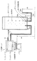
本発明の第1の実施の形態の液体供給装置を含む液体吐出記録装置の概略構成が、図1に模式的に示されている。これは、インクを吐出して記録を行うインクジェット方式の記録ヘッド11と、記録ヘッド11にインクを供給するインク供給装置とを有するインクジェット記録装置である。本実施形態では使用する液体としてインクを例にとって説明するが、本発明はこれに限られない。
【0026】
インク供給装置は、鉛直下向きに配置され、インクを収容するインクタンク22と、インクタンク22から記録ヘッド11にインクを供給するパイプ状の第1の連結部であるインク供給管17と、インクタンク22に大気を導入するパイプ状の第2の連結部である大気開放管26とを有している。
【0027】
インクタンク22は、例えば、厚さ0.5mm以上のポリエチレン、ポリプロピレン、ノリル等により形成された、容易には変形しない高剛性の筐体からなるものである。
【0028】
インク供給管17は、ステンレス等からなるパイプ状の針部24を含んでおり、この針部24は、インクタンク22の底面に設けられた孔部を塞ぐゴム栓25を貫通してインクタンク22の内部に挿入可能である。同様に、大気開放管26は、ステンレス等からなるパイプ状の針部30を含んでおり、この針部30は、インクタンク22の底面に設けられた孔部を塞ぐゴム栓31を貫通してインクタンク22の内部に挿入可能である。
【0029】
また、インク供給管17は垂直に立つ針部24の下端で水平方向に折れ曲がり、再び上向きに折れ曲がって記録ヘッド11のサブタンク12の底面付近の側壁からヘッド内部に連結されている。一方、大気開放管26は垂直に立つ針部30の下端で水平方向に折れ曲がり、再び上向きに折れ曲がっている。
【0030】
インクタンク22の底面に設けられている孔部は、未使用のインクタンク22にインクを注入する際には注入口として開放されており、インク注入後にゴム栓25,31により塞がれる。図1に示すように記録装置本体に装着される際に、針部24,30が、それぞれゴム栓25,31を貫通してインクタンク22内部に差し込まれる。それによって、針部24を含むインク供給管17(第1の連結部)を介して、インクタンク22と記録ヘッド11とが連通するとともに、針部30を含む大気開放管26(第2の連結部)を介して、インクタンク22内部が大気に開放されている。インクタンク22が記録装置本体に装着される前、または記録装置本体から取り外された後は、ゴム栓25,31が孔部を塞ぐので、インクタンク22からインクが流出することはない。このとき、針部24,30によって穴が開けられていても、ゴム栓25,31の弾性によって、針部24が引き抜かれると同時にその穴は塞がれる。
【0031】
記録ヘッド11は、図8に示す従来の記録ヘッド11と実質的に同じ構成であり、インクを吐出するノズル15と、各ノズル15に均等にインクを供給するためのインク溜りである共通液室14と、インク供給装置から供給されて共通液室14に至る前のインクを一時的に収容するサブタンク12と、サブタンク12から共通液室14へ供給されるインクに含まれているごみを取り除くためのフィルター13と、未使用の記録ヘッドに最初にインクを供給する際にポンプ(図示せず)などによりインクを吸入するためのインク吸引管18とを有している。記録ヘッド11はノズル15を下向きにしてノズル15と共通液室14とサブタンク12の位置が鉛直方向に並ぶように記録装置本体に装着される。
【0032】
このインクジェット記録装置においては、インクタンク22から、インク供給管17を介して、記録ヘッド11にインクが供給されている。記録ヘッド11の内部においては、サブタンク12にある程度の量のインクが収容され、そのサブタンク12から、共通液室14を介して各ノズル15までインクが供給されている。針部24を含むインク供給管17の内部は、全長に亘ってインクで満たされている。サブタンク12は、全容積がインクで満たされているのではなく、空気の溜まっている部分が残っている。また、インク吸引管18は記録ヘッド11内へのインク充填のためのインク吸引に用いられた後は図示しないバルブ等で密閉されており、インクが漏れないようになっている。各ノズル15の先端にはインクのメニスカス16が形成されており、このメニスカス16の表面張力により、インクが、垂れ落ちないようにノズル15の先端の吐出口付近に保持されている。
【0033】
本発明では、インクタンク22は、使用開始時には全容積がインクで満たされていてもよいが、インクが消費されてくると、全容積がインクで満たされているのではなく、空気の溜まっている部分が残っている状態になる。また、大気開放管26の先端26bが記録ヘッド11のノズル15の液体吐出口の高さより低い位置に在り、大気開放管26内にはインクと空気(外気)との界面が存在し、この界面にインクのメニスカス27が形成されている。これにより、通常の使用環境では、大気開放管26内のメニスカス27によって生じる表面張力の力により、記録ヘッド11のノズル15に対して一定の負圧が働いて、ノズル15からインクが漏れ出すことを防いでいる。この際、前記の負圧を発生させるメニスカス形成のために大気開放管26の内径の大きさが重要になってくる。ここでは、大気開放管26の内径は直径0.1mm〜10mm程度に設定され、より好ましくは、0.1mm〜2mm程度に設定される。
【0034】
上記の構成のインクジェット記録装置において、記録動作に伴う発熱等により記録ヘッド11内の温度が上がった場合、サブタンク12にある空気が膨張してサブタンク12内の圧力が上昇する。そこで、サブタンク12内のインクが、インク供給管17を通ってインクタンク22に逆流することによって、サブタンク12内の圧力上昇が解消される。逆流したインクは、インクタンク22に収容される。このとき、インクタンク22内の圧力が上昇するためインクタンク22内のインクが加圧され、大気開放管26の中に深く入り込む。すなわち、インクのメニスカス27の位置が降下する。圧力上昇が大きい場合には、大気開放管26が屈曲して水平に延びる中間部分までインクのメニスカス27が移動したり、極端な場合には、大気開放管26の折り曲げて上に向けられた開放端26aからインクが瞬間的に飛び出ることも考えられる。
【0035】
また、このインクジェット記録装置において、記録動作により記録ヘッド11内のインクが消費された場合、サブタンク12内のインクが減少してサブタンク12内の圧力が低下する。そこで、インクタンク22内のインクが、インク供給管17を通ってサブタンク12に流入することによって、サブタンク12内の圧力低下が解消される。それに伴って、インクタンク22内のインクが減少してインクタンク22内の圧力が低下するため、大気開放管26を介して大気が吸引され、インクタンク22中に気泡28がその減少したインクに見合うだけ取り込まれる。このとき、大気開放管26内のメニスカス27は、図1に示すようにインクタンク22内部の大気開放管26の先端26bに位置する。その後、適量の気泡(大気)28が取り込まれたら、インクタンク22内が所定の圧力に復帰して安定し、大気の取り込みが終了する。
【0036】
このように大気開放管26内におけるインクと大気の界面、すなわちメニスカス27が移動することによって、サブタンク12内の圧力変動が吸収され、記録ヘッド11内のインクの負圧状態は一定に保たれ、インクの垂れ落ちを防ぐノズル15内のメニスカス16に変化は生じない。
【0037】
従来のインク供給装置は、図8に示したように、インタンクであるアルミラミネート袋210の変形によって圧力変動を吸収するため、アルミラミネート袋210の変形が規制されないように、その周囲に十分なスペースを空けておく必要がある。また、記録ヘッド110のノズル150とアルミラミネート袋210との相対的な高さによって生じる水頭差hにより負圧を発生させているので、ノズル150とアルミラミネート袋210の配置に制限がある。
【0038】
これに対し、本発明のインク供給装置は、インクタンク22を大気に開放する大気開放管26に生じるインクと大気との界面のメニスカス27の移動によって圧力の変動を吸収するため、インクタンク22が変形する必要はなく、インクタンク22の周囲にスペースを空けておく必要はない。ノズル15からインクを漏れさせないための負圧を発生させるのは、記録ヘッド11のノズル15の先端の吐出口の位置と大気開放管26の先端26bの位置に依るので、インクタンク22の大きさには何の規制もない。特に、記録ヘッド11のノズル15とインクタンク22の上部との位置関係には何の規制対象とならないので、例えば、記録ヘッド11のノズル15より上側にインクタンク22の上部があっても全く問題ない。このインクタンク22は、収容すべきインク量に応じた筐体からなり、その全容積にインクを収容しておくことができるので、インク収容効率が非常に良好である。
【0039】
また、図1からも分かるように、ノズル15の先端の吐出口の位置(高さH1)と、通常の使用状態でメニスカスが形成される大気開放管26の先端26bの位置(高さH2)と、大気開放管26の開放端26aの位置(高さH3)との位置関係は、ノズル15からのインクの溢れを防ぐために、次のような関係をとる。
【0040】
▲1▼まず、ノズル15の吐出口と、インクタンク22の大気開放管26の先端26bとの位置関係は、上述しているように、H1>H2 としている。この位置関係によって、本例の液体供給装置は通常の使用環境において記録ヘッド11のノズル15からインクが流れ出すこともなく、一定の負圧がノズル15に働いて安定な吐出が行われる。
【0041】
▲2▼次に、インクタンク22の大気開放管26の先端26bと、大気開放管26の開放端26aとの位置関係は、図1に示すように、H2<H3 としている。
【0042】
記録ヘッドによる記録動作を停止している時に外気温が上がると、インクタンク22内に溜まっている空気が膨張する。この膨張は本例の液体供給装置ではノズル15から解消されるか、あるいは大気開放管26の開放端26aかのどちらかしかない。
【0043】
しかし、ノズル15のノズル径と大気開放管26の内径(穴径)とでは、大気開放管26の内径の方が大きくできているので、そこに出来るメニスカスによるインク保持力は圧倒的にノズルの方が大きい。そのため、空気の膨張は大気開放管26内部を通ってその開放端26aにインクが移動することで解消される。
【0044】
このとき、もしも H2>H3 なる関係であると、何らかの外乱によりノズル15でのメニスカス16が壊れてノズル15から空気が入り込んだ場合、記録ヘッド11、インクタンク22内のインクは全て大気開放管26の開放端26aの穴から流れ出てしまうおそれがある。したがって、この場合を考慮して、H2<H3 なる関係が望ましい。
【0045】
▲3▼さらに、ノズル15の吐出口と大気開放管26の開放端26aとの位置関係は、外気温が上昇した状態(インクが大気開放管26内部を通ってその開放端26a近くまでを満たしている状態)で、ノズル15からインクがあふれ出してしまうことになっては問題となるので、H1>H3 なる関係が望ましい。
【0046】
(第2の実施の形態)
図2は本発明の第2の実施の形態の液体供給装置を含む液体吐出記録装置を模式的に示している。図1に示したインク供給系では、記録装置機内の温度上昇や外気温の上昇等によりインクタンク内部に蓄積された空気が膨張し、インクタンク内のインクがインクタンクの外に出ようとし、大気開放管に入り込む。そのため、第1の実施の形態ではインクタンク内の圧力上昇を十分見越して、ノズルまたは大気開放管からインクが溢れ出ないような大気開放管の開放端の高さを設定している。しかし、第1の実施の形態のように大気開放管だけしか存在しない場合、インクタンクの内圧が急激に上昇すると、大気開放管の開放端からインクが飛び出て記録装置内を汚すことが起こり得る。
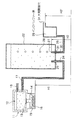
【0047】
そこで本実施形態では、図2に示すように、大気開放管26の折り曲げて上に向けられた端部に、インクタンク22から溢れ出したインクを一時保管するインク受け皿となるインクバッファー室29が接続され、インクバッファー室19の側壁の最上部に大気開放穴33が設けられている。このような構成により、インクタンク内の空気の膨張によってインクが機内へ飛び出す前にインクバッファー室19で、インクの飛び出しを抑えることができる。
【0048】
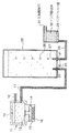
さらに好ましいインク供給系となるために、図3に示すように、大気開放穴33を有するインクバッファー室19の中にインク吸収体(例えばスポンジ)32を入れることで、インクバッファー室19でのインクの自由な動きを規制してもよい。あるいは、図4に示すように、インクバッファー室29に設けられた大気開放穴33の向きを下方に設けることで、インク供給系への空気中のごみの混入を防止することもできる。
【0049】
次に、環境変化によりインクタンク22より溢れ出すインクの受け皿となるインクバッファー室29の体積について説明する。
【0050】
インクタンク22の体積をV(一定)、インクタンク22内のインクの体積をVi、インクタンク22内の溜まった空気をVa、インクバッファー室29の体積をVB とすると、V(一定)=Vi+Va である。
【0051】
本例のインク供給系を含むインクジェット記録装置は一般的に5〜35℃の環境で使用され、さらに、記録装置の機内の温度上昇を15℃としても、インクタンク温度は50℃までしか上昇しないが、安全を考えて+10℃を追加して最大60℃まで上昇した場合を考える。
【0052】
5℃で使用していたインクジェット記録装置が60℃まで上昇したとすると、この時のインクタンク22内の空気の体積Va’は、
Va’=Va・(273+60)/(273+5)≒1.2Va
したがって、0.2Va分の空気がインクバッファー室29に向けて流れ出す。
【0053】
その流れ出すインク量の最大値を考えると、流れ出す0.2Vaに相当するインク量がインクタンク22内に残っていることが必要である。それは、
Vi=0.2Va
V−Va=0.2Va
∴Va=(1/1.2)V=(5/6)V
Va=(5/6)Vの時、インクタンク22より流れ出すインク量が最も大きくなる可能性があり、その最大値は、0.2Va=(1/5)×(5/6)V=(1/6)V
したがって、インクバッファー室29の体積VBは、VB≧(1/6)V の関係を満たす必要がある。
【0054】
さらに、本実施形態においても、第1の実施の形態と同様の理由で、▲1▼ノズル15の吐出口とインクタンク22の大気開放管26の先端26bとの位置関係をH1>H2とし、▲2▼インクタンク22の大気開放管26の先端26bと、インクバッファー室29の大気開放穴31との位置関係をH2<H3’とし、▲3▼ノズル15の吐出口とインクバッファー室29の大気開放穴31との位置関係をH1>H3’としている。
【0055】
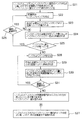
ここで、図5〜図7を参照し、図2に示した液体供給装置におけるインクの流れについて、A.通常の記録時、B.記録動作を停止している状態で外気温が上昇した時、C.外気温が上昇してインクバッファー室29にインクが溜まった状態で記録動作が開始された場合、をそれぞれ説明する。
【0056】
A.通常の記録時
記録前(図2に示す状態)は、ノズル15のメニスカス16による力と大気開放管26内のメニスカス27による力とが釣り合っている。このとき、インクバッファー室29は空である(図5のステップS1)。
【0057】
記録動作が開始されると、ノズル15よりインクが吐出される(図5のステップS2)。
【0058】
ノズル15からの吐出に必要なインクがインクタンク22から記録ヘッド11へ供給される(図5のステップS3)。
【0059】
そして、インクタンク22から供給されたインク量に応じた空気が大気開放管26からインクタンク22内に入り込む(図5のステップS4)。
【0060】
記録動作が継続している場合は、ステップS2からステップS4までの段階を繰り返す(図5のステップS5)。一方、記録動作が継続していない場合は、ノズル15のメニスカス16による力と大気開放管26のメニスカス27による力とが釣り合ってる状態で止まる。このとき、インクバッファー室29は空のままである(図5のステップS6)。
【0061】
B.記録動作を停止している状態で記録装置機内の温度や外気温等が上昇した時
記録を停止している状態(図2に示す状態)では、ノズル15のメニスカス16による力と大気開放管26内のメニスカス27による力とが釣り合っている。このときインクバッファー室29は空である(図6のステップS11)。
【0062】
外気温等が上昇すると、インクタンク22内に溜まっている空気が膨張する(図6のステップS12、S13)。大気開放管26内のメニスカス27が壊れ、空気が膨張した分のインクがインクバッファー室29に流れ出す(図6のステップS14)。
【0063】
この空気が膨張した分のインクがインクバッファー室29にて溜まり、大気開放穴31から漏れ出ない位置で止まる(図6のステップS15)。
【0064】
C.外気温等が上昇してインクバッファー室29にインクが溜まった状態で記録動作が開始された場合
図6のステップS15の状態では、インクバッファー室29はインクで満たされている。このとき、ノズル15のメニスカス16はインクバッファー室29内のインクの水位より高いので、その水頭差分で保持されている(図7のステップS21)。
【0065】
記録動作が開始されると、ノズル15よりインクが吐出される(図7のステップS22)。
【0066】
ノズル15からの吐出に必要なインクがインクタンク22から記録ヘッド11へ供給される(図7のステップS23)。
【0067】
インクタンク22から記録ヘッド11へ供給されたインク量に応じたインクが、インクバッファー室29よりインクタンク22へ供給される(図7のステップS24)。
【0068】
インクバッファー室29内にインクが残っている状態で、引き続いて記録動作を行う場合は、ステップS2からステップS4までの段階を繰り返す(図7のステップS25、S26)。インクバッファー室29内にインクが残っている状態で、記録動作が停止した場合は、ノズル15のメニスカス16はインクバッファー室29内のインクの水位より高いので、その水頭差分で保持されている(図7のステップS27)。
【0069】
また、インクバッファー室29内にインクが残っていない状態で、ノズル15よりインクを吐出しているときは、ノズル15からの吐出に必要なインクがインクタンク22から記録ヘッド11へ供給され、インクタンク22から記録ヘッド11へ供給されたインク量に応じた空気が、大気開放管26よりインクタンク22内に入り込む(図7のステップS28〜S30)。
【0070】
引き続いて記録動作を行う場合は、ステップS2からステップS4までの段階を繰り返す(図7のステップS31)。一方、記録動作が停止した場合は、ノズル15のメニスカス16による力と大気開放管26のメニスカス27による力とが釣り合っている状態でインクの流れが止まる。このとき、インクバッファー室29は空の状態である。
【0071】
このように本実施形態の構造によれば、上記のA、B、Cの場合において記録装置の機内へのインク溢れが無い良好な記録動作が可能である。
【0072】
なお、以上に説明した第1及び第2の実施の形態では、1個のインクタンク22および1個の記録ヘッド11について詳述したが、カラー記録などのため複数種類のインクを用いる必要があり複数のインクタンク22および記録ヘッド11が設けられる場合、図1に示す構成を複数並べて設置すればよい。
【0073】
本発明は、記録ヘッド11が被記録媒体(図示せず)の搬送方向と交差する方向に往復移動しながら被記録媒体にインク吐出を行うシリアルタイプのインクジェット記録装置にも、記録ヘッド11が被記録媒体の記録領域の全幅以上の長さを有し移動せずにインク吐出を行うフルラインタイプのインクジェット記録装置にも適用できる。また、本発明の記録ヘッド11の構成は、図示した例には限定されず、流路や液室の構成が異なっていてもよい。インク吐出の原理に関しても、バブルジェット方式に限定されるものではなく、いかなる構成および吐出原理のインクジェット記録ヘッドであっても構わない。
【0074】
【発明の効果】
本発明によれば、液体を吐出する液体吐出ヘッドを用いて記録を行なう液体吐出記録装置に用いられ、記録ヘッドに対して供給すべき液体をそれ自身が容易に変形することの無い材質でできた筐体からなる液体収納容器と、液体収納容器の底面からそれぞれ下方に伸び、途中で上方に折り曲げられた管状の第1および第2の連結部とを有し、第1の連結部は記録ヘッドと連結されており、第2の連結部は液体収納容器の内部を大気に連通させた液体供給装置において、第2の連結部の液体収納容器内に入れられた一端を記録ヘッドの液体吐出口の高さより低い位置に設け、かつ、大気に開放されている第2の連結部の他端を前記記録ヘッドの液体吐出口の高さより低い位置に設けるとともに前記第2の連結部の一端よりも高い位置に設け、第2の連結部内に液体と大気の界面が存在するように構成し、その界面に形成されたメニスカスの表面張力の力により、記録ヘッドの液体吐出口に対して負圧を発生させていることにより、通常の使用環境は勿論のこと、使用環境の周囲温度が大きく変化しても、記録ヘッドの液体吐出口から液体が垂れ落ちないようにして、安定した吐出を実現することが可能である。
【0075】
このような液体供給系に用いる液体収納容器(インクタンク)は、変形する必要がなく単なる筐体であればよいので、材質の制約が少なく、低コストで簡単に製造できる。そして、液体収納容器の全容積に液体(インク)を充填させておくことができ、しかも液体収納容器の周囲にスペースを確保する必要がないため、液体の収容効率がとてもよい。そして、液体供給装置をあまり大型化せずにすむため、液体供給装置を備えた液体吐出記録装置(インクジェット記録装置)全体の省スペース化に寄与する。特に、大量または多種の液体を収容する必要がある、大量印刷や精細なカラー記録が可能な液体吐出記録装置においては、本発明により大型化を避ける構成とすることが極めて効果的である。
【0076】
また、上記の第2の連結部の液体収納容器から大気開放穴までの間に、液体収納容器内の空気が温度上昇によって膨張することで液体収納容器外に押し出した液体の受け皿となるバッファー室を設けたことにより、液体収納容器の液体で記録装置の機内が汚れることを防ぐことができる。
【図面の簡単な説明】
【図1】本発明の第1の実施の形態の液体供給装置(インク供給装置)を含む液体吐出記録装置(インクジェット記録装置)の概略構成を模式的に示す図である。
【図2】本発明の第2の実施の形態の液体供給装置(インク供給装置)を含む液体吐出記録装置(インクジェット記録装置)の概略構成を模式的に示す図である。
【図3】図2に示すインクバッファー室の変形例を示す図である。
【図4】図2に示すインクバッファー室の変形例を示す図である。
【図5】図2の液体供給装置において記録ヘッドが通常の記録動作を行なっているときのインクの流れを説明するためのフローチャートである。
【図6】図2の液体供給装置において記録ヘッドが記録動作を行なっていない状態で外気温が上昇した時のインクの流れを説明するためのフローチャートである。
【図7】図2の液体供給装置において、外気温が上昇してインクバッファー室にインクが溜まった状態で記録動作が開始された場合のインクの流れを説明するためのフローチャートである。
【図8】従来のインク供給装置を含むインクジェット記録装置の要部を示す模式図である。
【符号の説明】
11 記録ヘッド
12 サブタンク
13 フィルター
14 共通液室
15 ノズル
16 メニスカス
17 インク供給管(第1の連結部材)
18 インク吸引管
22 インクタンク
24 針部
25 ゴム栓
26 大気開放管(第2の連結部材)
26a 開放端(他端)
26b 先端(一端)
27 メニスカス
28 気泡
29 インクバッファー室
30 針部
31 ゴム栓
32 インク吸収体
33 大気開放穴[0001]
BACKGROUND OF THE INVENTION
The present invention relates to a liquid discharge recording apparatus that performs recording by discharging a recording liquid onto a recording material, and a liquid supply apparatus used therefor.
[0002]
[Prior art]
As a form of a recording apparatus that forms an image (here, an image including characters, figures, patterns, etc., regardless of whether there is a meaning) on a recording material such as recording paper, a minute ink from a minute ejection port There is an ink jet recording apparatus that ejects droplets. In general, an ink jet recording apparatus has a recording head having nozzles for ejecting ink droplets, and an ink tank for storing ink to be supplied to the recording head. Then, the ink is guided from the ink tank to the recording head, and an energy generator such as a heating element or a piezoelectric element provided near the ejection port of the nozzle of the recording head is driven based on the recording signal, and the ink is ejected from the ejection port. Recording is performed by discharging droplets and adhering to the recording material. This ink jet recording apparatus is a so-called non-impact recording apparatus, and can be recorded at high speed and on various recording media, and has the advantage that noise during recording hardly occurs. It is popular.
[0003]
In this ink jet recording apparatus, in addition to a predetermined amount of fine ink droplets to be ejected, ink flows out from the ejection port, that is, ink leaks out from the ejection port during non-driving (such as during recording standby) In order to prevent an excessive outflow of ink from the inside ejection port, it is necessary to always keep the ink in a negative pressure state at the ejection port.
[0004]
Conventionally, in order to keep the ink in a negative pressure state, a configuration has been adopted in which the height of the ink tank containing the ink is made lower than that of the ejection port and the water head difference is utilized. In order to keep the ink holding pressure defined by the water head difference constant in any state, the volume of the ink tank needs to change according to the amount of ink inside. . For example, when ink is supplied to the recording head and the amount of ink in the ink tank decreases, the volume of the ink tank decreases accordingly, and when ink flows from the recording head and the amount of ink in the ink tank increases, Accordingly, it is necessary to adopt a configuration in which the volume of the ink tank increases. Therefore, in general, a flexible container such as an aluminum laminate bag is used as the ink tank.
[0005]
A schematic configuration of an ink jet recording apparatus having such a conventional ink jet supply apparatus is schematically shown in FIG. This includes an ink
[0006]
The ink supply device includes a flexible aluminum laminated bag (ink tank) 210 that contains ink, a
[0007]
The
[0008]
In this ink jet recording apparatus, the
[0009]
In this conventional ink jet recording apparatus, when the temperature in the
[0010]
Further, in this ink jet recording apparatus, when the ink in the
[0011]
As described above, the ink flows between the
[Prior Art Documents] JP-A-11-138841
[0012]
[Problems to be solved by the invention]
As described above, in the conventional ink jet recording apparatus, the ink pressure is adjusted by deformation of the flexible
[0013]
On the other hand, in recent years, an ink jet recording apparatus may be used when a large amount of printing is required with improvement in performance such as high speed, high durability, quietness, and low running cost of the ink jet recording apparatus. Accordingly, the ink capacity of the ink tank is also required to be increased. The ink jet recording method is easy to color, and in recent years, most ink jet recording apparatuses can perform color recording. Therefore, a large number of inks such as four colors, six colors, or seven colors are required in addition to one black color, and it is necessary to provide a large number of large-capacity ink tanks. It has become. In such a situation, the conventional configuration shown in FIG. 8 uses a deformable ink tank such as a flexible aluminum laminated
[0014]
As described above, the conventional inkjet recording apparatus has a large number of factors that increase the size, and it is difficult to meet the demand for reduction in size and weight in consideration of convenience and the like. In the end, in conventional inkjet recording apparatuses, it has been impossible to achieve both large-scale printing and fine color recording that require an increase in size and reduction in size and weight in order to improve convenience.
[0015]
Therefore, an object of the present invention is to adjust the negative pressure with respect to the recording head nozzle for preventing dripping of ink without depending on the deformation of the ink tank in the system for supplying ink from the ink tank to the inkjet head. An object of the present invention is to provide an ink supply device (liquid supply device) that can contribute to downsizing of the device as compared with the configuration and an ink jet recording device (liquid discharge recording device) using the ink supply device.
[0016]
[Means for Solving the Problems]
In order to achieve the above object, the present invention provides a liquid supply apparatus that supplies liquid to a recording head that discharges liquid,
A liquid storage container for storing the liquid to be supplied to the recording head, a first connecting portion for connecting the recording head and the liquid storage container, one end in the liquid storage container and the other end being opened to the atmosphere. A second connecting portion,
One end of the second connecting portion connected to the liquid storage container is at a position lower than the height of the liquid discharge port of the recording head,And the other end of the second connecting portion that is open to the atmosphere is at a position lower than the height of the liquid ejection port of the recording head and at a position higher than one end of the second connecting portion. AndAn interface between the liquid and the atmosphere exists in the second connecting portion, and a negative pressure is generated with respect to the liquid discharge port of the recording head by the surface tension of the meniscus formed at the interface.
Each of the first connecting portion and the second connecting portion extends downward from the bottom surface of the liquid container, and is bent upward in the middle.The negative pressure is kept constant by moving the interface in the second connecting portion in accordance with pressure fluctuations in the liquid storage container and the recording head.It is characterized by that.
[0017]
In this liquid supply apparatus, the other end of the second connecting part that is open to the atmosphere is higher than one end of the second connecting part, and is lower than the height of the liquid ejection port of the recording head. More preferably.
[0018]
Furthermore, it is preferable that a buffer chamber for temporarily storing the liquid overflowing from the liquid storage container is provided between both ends of the second connecting portion. In this case, it is preferable that a liquid absorbing member is contained in the buffer chamber, or the air communication hole provided in the buffer chamber is directed downward.
[0020]
Further, the first connecting portion supplies liquid from the liquid storage container to the recording head when the liquid in the recording head is consumed, and the second connecting portion is provided in the liquid storage container. When the pressure decreases, the atmosphere is introduced into the liquid storage container.
[0021]
As described above, in the liquid supply apparatus according to the present invention, the liquid storage container that stores the liquid to be supplied to the recording head, the first connecting portion that connects the recording head and the liquid storage container, and one end of the liquid storage container are in the liquid storage container A second connecting portion having the other end open to the atmosphere, and one end of the second connecting portion connected to the liquid storage container is provided at a position lower than the height of the liquid discharge port of the recording head. The interface between the liquid and the atmosphere exists in the connecting portion of the recording head, and the surface tension of the meniscus formed at the interface generates a negative pressure on the liquid ejection port of the recording head. The liquid is prevented from dripping from the discharge port of the recording head. Further, the negative pressure is kept constant by moving the interface in the second connecting portion in accordance with pressure fluctuations in the liquid storage container and the recording head. Therefore, the liquid storage container does not need to be deformed and may be a simple case, so there are few restrictions on the material and it can be easily manufactured at low cost. Since the liquid can be filled in the entire volume of the liquid storage container and it is not necessary to secure a space around the liquid storage container, the liquid storage efficiency is very good. Further, since the liquid supply apparatus does not need to be increased in size, it contributes to space saving of the entire liquid discharge recording apparatus provided with the liquid supply apparatus.
[0022]
Further, the present invention also includes a liquid discharge recording apparatus that includes the liquid supply apparatus configured as described above and the recording head, and performs recording by discharging liquid from the recording head onto a recording medium. According to this, since the liquid supply apparatus is not so large, the entire liquid discharge recording apparatus can be miniaturized. This is particularly effective for a liquid discharge recording apparatus that performs mass printing and fine color recording.
[0023]
Further, by providing a buffer chamber for temporarily storing the liquid between both ends of the second connecting portion, the buffer chamber is pushed out of the liquid storage container due to the expansion of the air in the liquid storage container due to the temperature rise. Thus, it becomes possible to prevent the inside of the recording apparatus from being soiled by the liquid in the liquid storage container.
[0024]
DETAILED DESCRIPTION OF THE INVENTION
Embodiments of the present invention will be described below with reference to the drawings.
[0025]
(First embodiment)
A schematic configuration of a liquid discharge recording apparatus including a liquid supply apparatus according to a first embodiment of the present invention is schematically shown in FIG. This is an ink jet recording apparatus having an ink jet recording head 11 that performs recording by discharging ink, and an ink supply device that supplies ink to the recording head 11. In the present embodiment, ink will be described as an example of the liquid to be used, but the present invention is not limited to this.
[0026]
The ink supply device is arranged vertically downward, and stores an
[0027]
The
[0028]
The
[0029]
Further, the
[0030]
The hole provided in the bottom surface of the
[0031]
The recording head 11 has substantially the same configuration as the conventional recording head 11 shown in FIG. 8, and a common liquid chamber which is a
[0032]
In this ink jet recording apparatus, ink is supplied from the
[0033]
In the present invention, the
[0034]
In the ink jet recording apparatus having the above configuration, when the temperature in the recording head 11 rises due to heat generated by the recording operation, the air in the
[0035]
Further, in this ink jet recording apparatus, when the ink in the recording head 11 is consumed by the recording operation, the ink in the
[0036]
In this way, when the ink-atmosphere interface in the
[0037]
As shown in FIG. 8, the conventional ink supply device absorbs pressure fluctuations due to the deformation of the aluminum laminated
[0038]
In contrast, the ink supply device of the present invention absorbs pressure fluctuations by the movement of the
[0039]
Further, as can be seen from FIG. 1, the position (height H1) of the discharge port at the tip of the
[0040]
(1) First, the positional relationship between the discharge port of the
[0041]
(2) Next, as shown in FIG. 1, the positional relationship between the
[0042]
If the outside air temperature rises when the recording operation by the recording head is stopped, the air accumulated in the
[0043]
However, the nozzle diameter of the
[0044]
At this time, if the relationship of H2> H3 is satisfied, if the
[0045]
(3) Further, the positional relationship between the discharge port of the
[0046]
(Second Embodiment)
FIG. 2 schematically shows a liquid discharge recording apparatus including a liquid supply apparatus according to a second embodiment of the present invention. In the ink supply system shown in FIG. 1, the air accumulated in the ink tank expands due to a rise in temperature inside the recording apparatus or an outside air temperature, and the ink in the ink tank tends to come out of the ink tank. Enter the open air pipe. For this reason, in the first embodiment, the height of the open end of the air release pipe is set so that ink does not overflow from the nozzle or the air release pipe in anticipation of the pressure increase in the ink tank. However, in the case where only the atmosphere open pipe exists as in the first embodiment, if the internal pressure of the ink tank suddenly rises, the ink may protrude from the open end of the atmosphere open pipe and stain the inside of the recording apparatus. .
[0047]
Therefore, in the present embodiment, as shown in FIG. 2, an ink buffer chamber 29 serving as an ink tray for temporarily storing the ink overflowing from the
[0048]
In order to provide a more preferable ink supply system, as shown in FIG. 3, an ink absorber (for example, sponge) 32 is placed in the ink buffer chamber 19 having the atmosphere opening hole 33, so that the ink in the ink buffer chamber 19 can be obtained. You may restrict free movement. Alternatively, as shown in FIG. 4, the atmosphere opening hole 33 provided in the ink buffer chamber 29 is provided in the downward direction, so that dust in the air can be prevented from entering the ink supply system.
[0049]
Next, the volume of the ink buffer chamber 29 serving as a tray for the ink overflowing from the
[0050]
The volume of the
[0051]
The ink jet recording apparatus including the ink supply system of this example is generally used in an environment of 5 to 35 ° C. Further, even if the temperature rise in the apparatus of the recording apparatus is 15 ° C., the ink tank temperature only rises to 50 ° C. However, in consideration of safety, a case where the temperature rises to a maximum of 60 ° C. by adding + 10 ° C.
[0052]
Assuming that the ink jet recording apparatus used at 5 ° C. has risen to 60 ° C., the volume Va ′ of air in the
Va ′ = Va · (273 + 60) / (273 + 5) ≈1.2Va
Therefore, 0.2Va of air flows out toward the ink buffer chamber 29.
[0053]
Considering the maximum value of the ink amount that flows out, it is necessary that the ink amount corresponding to 0.2 Va that flows out remains in the
Vi = 0.2Va
V-Va = 0.2Va
∴Va = (1 / 1.2) V = (5/6) V
When Va = (5/6) V, there is a possibility that the amount of ink flowing out from the
Therefore, the volume V of the ink buffer chamber 29BIs VBIt is necessary to satisfy the relationship of ≧ (1/6) V.
[0054]
Further, in the present embodiment, for the same reason as in the first embodiment, (1) the positional relationship between the discharge port of the
[0055]
Here, with reference to FIGS. 5 to 7, the ink flow in the liquid supply apparatus shown in FIG. When the outside air temperature rises while the recording operation is stopped, C. The case where the recording operation is started in a state where the outside air temperature rises and ink is accumulated in the ink buffer chamber 29 will be described.
[0056]
A. During normal recording
Before recording (the state shown in FIG. 2), the force of the
[0057]
When the recording operation is started, ink is ejected from the nozzle 15 (step S2 in FIG. 5).
[0058]
Ink necessary for ejection from the
[0059]
Then, air corresponding to the amount of ink supplied from the
[0060]
If the recording operation continues, the steps from step S2 to step S4 are repeated (step S5 in FIG. 5). On the other hand, when the recording operation is not continued, the force is stopped in a state where the force of the
[0061]
B. When the temperature inside the recorder or outside temperature rises while the recording operation is stopped
In the state where the recording is stopped (the state shown in FIG. 2), the force of the
[0062]
When the outside air temperature rises, the air accumulated in the
[0063]
Ink corresponding to the expansion of the air accumulates in the ink buffer chamber 29 and stops at a position where it does not leak from the air opening hole 31 (step S15 in FIG. 6).
[0064]
C. When the recording operation is started when the outside air temperature rises and ink is accumulated in the ink buffer chamber 29
In the state of step S15 in FIG. 6, the ink buffer chamber 29 is filled with ink. At this time, since the
[0065]
When the recording operation is started, ink is ejected from the nozzle 15 (step S22 in FIG. 7).
[0066]
Ink necessary for ejection from the
[0067]
Ink corresponding to the amount of ink supplied from the
[0068]
When the recording operation is subsequently performed with ink remaining in the ink buffer chamber 29, the steps from Step S2 to Step S4 are repeated (Steps S25 and S26 in FIG. 7). When the recording operation is stopped with ink remaining in the ink buffer chamber 29, the
[0069]
Further, when ink is ejected from the
[0070]
When the recording operation is subsequently performed, the steps from Step S2 to Step S4 are repeated (Step S31 in FIG. 7). On the other hand, when the recording operation is stopped, the ink flow is stopped in a state where the force of the
[0071]
As described above, according to the structure of the present embodiment, in the case of the above A, B, and C, it is possible to perform a good recording operation without causing ink overflow into the printing apparatus.
[0072]
In the first and second embodiments described above, one
[0073]
The present invention is also applicable to a serial type ink jet recording apparatus that discharges ink to a recording medium while the recording head 11 reciprocates in a direction intersecting the conveyance direction of the recording medium (not shown). The present invention can also be applied to a full-line type inkjet recording apparatus that has a length that is equal to or greater than the entire width of the recording area of the recording medium and that ejects ink without moving. Further, the configuration of the recording head 11 of the present invention is not limited to the illustrated example, and the configuration of the flow path and the liquid chamber may be different. The principle of ink ejection is not limited to the bubble jet method, and an ink jet recording head having any configuration and principle of ejection may be used.
[0074]
【The invention's effect】
According to the present invention, it is used in a liquid discharge recording apparatus that performs recording using a liquid discharge head that discharges liquid, and the liquid to be supplied to the print head can be made of a material that does not easily deform itself. And a tubular first and second connecting portions extending downward from the bottom surface of the liquid storing container and bent upward in the middle, the first connecting portion being a recording In the liquid supply apparatus in which the interior of the liquid storage container is connected to the atmosphere, the second connection part is connected to the head, and one end of the second connection part placed in the liquid storage container is connected to the liquid discharge container of the recording head. Set at a position lower than the height of the exit,In addition, the other end of the second connecting portion that is open to the atmosphere is provided at a position lower than the height of the liquid ejection port of the recording head and at a position higher than one end of the second connecting portion,An interface between the liquid and the atmosphere exists in the second connecting portion, and a negative pressure is generated at the liquid discharge port of the recording head by the force of the surface tension of the meniscus formed at the interface. Therefore, it is possible to realize stable discharge by preventing liquid from dripping from the liquid discharge port of the recording head even if the ambient temperature of the use environment changes greatly as well as the normal use environment. .
[0075]
The liquid storage container (ink tank) used for such a liquid supply system is not required to be deformed and may be a simple case, so that there are few material restrictions and can be easily manufactured at low cost. Since the liquid (ink) can be filled in the entire volume of the liquid storage container, and it is not necessary to secure a space around the liquid storage container, the liquid storage efficiency is very good. Since the liquid supply apparatus does not need to be increased in size, it contributes to space saving of the entire liquid discharge recording apparatus (inkjet recording apparatus) provided with the liquid supply apparatus. In particular, in a liquid discharge recording apparatus capable of mass printing and fine color recording that needs to contain a large amount or various kinds of liquids, it is extremely effective to avoid the increase in size according to the present invention.
[0076]
In addition, a buffer chamber serving as a tray for the liquid pushed out of the liquid storage container as the air in the liquid storage container expands due to a temperature rise between the liquid storage container of the second connecting portion and the air opening hole. By providing this, it is possible to prevent the inside of the recording apparatus from being contaminated by the liquid in the liquid storage container.
[Brief description of the drawings]
FIG. 1 is a diagram schematically illustrating a schematic configuration of a liquid discharge recording apparatus (inkjet recording apparatus) including a liquid supply apparatus (ink supply apparatus) according to a first embodiment of the present invention.
FIG. 2 is a diagram schematically illustrating a schematic configuration of a liquid discharge recording apparatus (inkjet recording apparatus) including a liquid supply apparatus (ink supply apparatus) according to a second embodiment of the present invention.
3 is a view showing a modification of the ink buffer chamber shown in FIG. 2. FIG.
4 is a view showing a modified example of the ink buffer chamber shown in FIG. 2. FIG.
FIG. 5 is a flowchart for explaining the flow of ink when the recording head performs a normal recording operation in the liquid supply apparatus of FIG. 2;
6 is a flowchart for explaining the flow of ink when the outside air temperature rises in a state where the recording head is not performing a recording operation in the liquid supply apparatus of FIG.
7 is a flowchart for explaining the ink flow when the recording operation is started in a state where the outside air temperature rises and ink is accumulated in the ink buffer chamber in the liquid supply apparatus of FIG.
FIG. 8 is a schematic diagram showing a main part of an ink jet recording apparatus including a conventional ink supply apparatus.
[Explanation of symbols]
11 Recording head
12 Sub tank
13 Filter
14 Common liquid chamber
15 nozzles
16 Meniscus
17 Ink supply pipe (first connecting member)
18 Ink suction tube
22 Ink tank
24 needle
25 Rubber stopper
26 Atmospheric open pipe (second connecting member)
26a Open end (other end)
26b Tip (one end)
27 Meniscus
28 Bubbles
29 Ink buffer chamber
30 needle
31 Rubber stopper
32 Ink absorber
33 Open air hole
Claims (4)
前記記録ヘッドに供給する液体を収納する液体収納容器と、前記記録ヘッドと前記液体収納容器とを連結する第1の連結部と、一端が前記液体収納容器内にあり他端が大気に開放されている第2の連結部とを有し、
前記液体収納容器に連結する前記第2の連結部の一端が前記記録ヘッドの液体吐出口の高さより低い位置に在り、かつ、大気に開放されている前記第2の連結部の他端が前記記録ヘッドの液体吐出口の高さより低い位置に在るとともに前記第2の連結部の一端よりも高い位置にある構成となっており、前記第2の連結部内に液体と大気との界面が存在し、前記界面に形成されるメニスカスの表面張力により、前記記録ヘッドの液体吐出口に対して負圧を発生させ、
前記第1の連結部および前記第2の連結部はそれぞれ前記液体収納容器の底面から下方に伸び、途中で上方に折り曲げられており、前記液体収納容器内および前記記録ヘッド内の圧力変動に応じて前記第2の連結部内の前記界面が移動することにより前記負圧が一定に保たれることを特徴とする液体供給装置。A liquid supply apparatus that supplies liquid to a recording head that discharges liquid,
A liquid storage container for storing the liquid to be supplied to the recording head, a first connecting portion for connecting the recording head and the liquid storage container, one end in the liquid storage container and the other end being opened to the atmosphere. A second connecting portion,
One end of the second connecting portion connected to the liquid storage container is at a position lower than the height of the liquid discharge port of the recording head, and the other end of the second connecting portion opened to the atmosphere is the The recording head is located at a position lower than the height of the liquid discharge port of the recording head and at a position higher than one end of the second connecting portion, and an interface between the liquid and the atmosphere exists in the second connecting portion. Then, due to the surface tension of the meniscus formed at the interface, a negative pressure is generated with respect to the liquid discharge port of the recording head,
Each of the first connecting portion and the second connecting portion extends downward from the bottom surface of the liquid storage container, and is bent upward in the middle, depending on pressure fluctuations in the liquid storage container and the recording head. The liquid supply device is characterized in that the negative pressure is kept constant by moving the interface in the second connecting portion .
Priority Applications (2)
| Application Number | Priority Date | Filing Date | Title |
|---|---|---|---|
| JP2002039225A JP3977097B2 (en) | 2001-08-01 | 2002-02-15 | Liquid supply apparatus and liquid discharge recording apparatus |
| US10/202,911 US6726315B2 (en) | 2001-08-01 | 2002-07-26 | Liquid supplying device and liquid discharge recording apparatus |
Applications Claiming Priority (3)
| Application Number | Priority Date | Filing Date | Title |
|---|---|---|---|
| JP2001-233465 | 2001-08-01 | ||
| JP2001233465 | 2001-08-01 | ||
| JP2002039225A JP3977097B2 (en) | 2001-08-01 | 2002-02-15 | Liquid supply apparatus and liquid discharge recording apparatus |
Publications (3)
| Publication Number | Publication Date |
|---|---|
| JP2003112435A JP2003112435A (en) | 2003-04-15 |
| JP2003112435A5 JP2003112435A5 (en) | 2005-07-21 |
| JP3977097B2 true JP3977097B2 (en) | 2007-09-19 |
Family
ID=26619759
Family Applications (1)
| Application Number | Title | Priority Date | Filing Date |
|---|---|---|---|
| JP2002039225A Expired - Fee Related JP3977097B2 (en) | 2001-08-01 | 2002-02-15 | Liquid supply apparatus and liquid discharge recording apparatus |
Country Status (2)
| Country | Link |
|---|---|
| US (1) | US6726315B2 (en) |
| JP (1) | JP3977097B2 (en) |
Families Citing this family (46)
| Publication number | Priority date | Publication date | Assignee | Title |
|---|---|---|---|---|
| US7147310B2 (en) * | 2002-01-30 | 2006-12-12 | Hewlett-Packard Development Company, L.P. | Printing-fluid container |
| US7744202B2 (en) * | 2002-01-30 | 2010-06-29 | Hewlett-Packard Development Company, L.P. | Printing-fluid container |
| US7452061B2 (en) * | 2002-01-30 | 2008-11-18 | Hewlett-Packard Development Company, L.P. | Method and device for filling a printing-fluid container |
| JP4086515B2 (en) | 2002-02-15 | 2008-05-14 | キヤノン株式会社 | Seal member, connection structure using the same, and liquid jet recording head |
| US7055941B2 (en) * | 2003-02-14 | 2006-06-06 | Canon Kabushiki Kaisha | Liquid storage container, and liquid discharge recording apparatus using the container |
| US7374355B2 (en) * | 2004-01-21 | 2008-05-20 | Silverbrook Research Pty Ltd | Inkjet printer cradle for receiving a pagewidth printhead cartridge |
| US7364263B2 (en) * | 2004-01-21 | 2008-04-29 | Silverbrook Research Pty Ltd | Removable inkjet printer cartridge |
| US7303255B2 (en) * | 2004-01-21 | 2007-12-04 | Silverbrook Research Pty Ltd | Inkjet printer cartridge with a compressed air port |
| US7232208B2 (en) * | 2004-01-21 | 2007-06-19 | Silverbrook Research Pty Ltd | Inkjet printer cartridge refill dispenser with plunge action |
| US7524016B2 (en) * | 2004-01-21 | 2009-04-28 | Silverbrook Research Pty Ltd | Cartridge unit having negatively pressurized ink storage |
| US7097291B2 (en) * | 2004-01-21 | 2006-08-29 | Silverbrook Research Pty Ltd | Inkjet printer cartridge with ink refill port having multiple ink couplings |
| US20050157112A1 (en) * | 2004-01-21 | 2005-07-21 | Silverbrook Research Pty Ltd | Inkjet printer cradle with shaped recess for receiving a printer cartridge |
| US7731327B2 (en) * | 2004-01-21 | 2010-06-08 | Silverbrook Research Pty Ltd | Desktop printer with cartridge incorporating printhead integrated circuit |
| US7645025B2 (en) * | 2004-01-21 | 2010-01-12 | Silverbrook Research Pty Ltd | Inkjet printer cartridge with two printhead integrated circuits |
| US7448734B2 (en) | 2004-01-21 | 2008-11-11 | Silverbrook Research Pty Ltd | Inkjet printer cartridge with pagewidth printhead |
| US7469989B2 (en) * | 2004-01-21 | 2008-12-30 | Silverbrook Research Pty Ltd | Printhead chip having longitudinal ink supply channels interrupted by transverse bridges |
| US7441865B2 (en) * | 2004-01-21 | 2008-10-28 | Silverbrook Research Pty Ltd | Printhead chip having longitudinal ink supply channels |
| US7121655B2 (en) * | 2004-01-21 | 2006-10-17 | Silverbrook Research Pty Ltd | Inkjet printer cartridge refill dispenser |
| GB2412088B (en) * | 2004-03-19 | 2007-09-19 | Zipher Ltd | Liquid supply system |
| US20060221114A1 (en) * | 2005-04-04 | 2006-10-05 | Silverbrook Research Pty Ltd | MEMS fluid sensor |
| US8141992B2 (en) | 2006-03-24 | 2012-03-27 | Seiko Epson Corporation | Liquid storage container |
| CN101817261B (en) | 2006-03-24 | 2013-01-23 | 精工爱普生株式会社 | Ink container |
| JP4424442B2 (en) | 2006-03-24 | 2010-03-03 | セイコーエプソン株式会社 | Liquid container |
| WO2007122793A1 (en) | 2006-03-24 | 2007-11-01 | Seiko Epson Corporation | Liquid container |
| US7703903B2 (en) * | 2006-07-10 | 2010-04-27 | Silverbrook Research Pty Ltd | Ink reservoir for inkjet printhead |
| WO2008006139A1 (en) * | 2006-07-10 | 2008-01-17 | Silverbrook Research Pty Ltd | Ink pressure regulator with bubble point pressure regulation |
| US7857441B2 (en) * | 2006-12-18 | 2010-12-28 | Silverbrook Research Pty Ltd | Ink pressure regulator |
| US7794068B2 (en) * | 2006-12-18 | 2010-09-14 | Silverbrook Research Pty Ltd | Method of regulating ink pressure |
| US7722170B2 (en) | 2006-12-18 | 2010-05-25 | Silverbrook Research Pty Ltd | Ink pressure regulator using air bubbles drawn into headspace |
| US7703901B2 (en) * | 2006-12-18 | 2010-04-27 | Silverbrook Research Pty Ltd | Printhead ink supply system comprising ink pressure regulator |
| US7784925B2 (en) * | 2006-12-18 | 2010-08-31 | Silverbrook Research Pty Ltd | Ink cartridge with pressure regulation |
| US7794038B2 (en) | 2006-12-18 | 2010-09-14 | Silverbrook Research Pty Ltd | Ink pressure regulator with regulator channel fluidically isolated from ink reservoir |
| US7703900B2 (en) * | 2006-12-18 | 2010-04-27 | Silverbrook Research Pty Ltd | Ink pressure regulator using air bubbles drawn into ink |
| WO2008074049A1 (en) | 2006-12-18 | 2008-06-26 | Silverbrook Research Pty Ltd | Ink pressure regulator |
| KR20080067926A (en) * | 2007-01-17 | 2008-07-22 | 삼성전자주식회사 | Ink tank and inkjet printer having the same |
| US7766470B2 (en) * | 2007-05-23 | 2010-08-03 | Lexmark International, Inc. | Ink jet printhead cartridge having an ink fill access port in fluid communication with the filter tower |
| US7841684B2 (en) * | 2007-10-16 | 2010-11-30 | Silverbrook Research Pty Ltd | Ink pressure regulator with improved liquid retention in regulator channel |
| JP5015200B2 (en) * | 2008-09-02 | 2012-08-29 | 株式会社リコー | Image forming apparatus |
| JP5645367B2 (en) * | 2009-03-10 | 2014-12-24 | キヤノン株式会社 | Liquid ejecting apparatus and method for controlling liquid ejecting apparatus |
| JP5807496B2 (en) * | 2011-09-30 | 2015-11-10 | ブラザー工業株式会社 | Image recording device |
| JP2013230651A (en) * | 2012-05-01 | 2013-11-14 | Saito Takashi | Inkjet recording device |
| CN104290455B (en) * | 2013-07-18 | 2016-08-10 | 北大方正集团有限公司 | A kind of ink-feeding device and the forming method of print nozzles surface meniscus |
| TWI649212B (en) | 2015-04-03 | 2019-02-01 | 佳能股份有限公司 | Liquid discharge device, imprinting device and component manufacturing method |
| JP6825219B2 (en) * | 2016-03-31 | 2021-02-03 | ブラザー工業株式会社 | Inkjet recording device |
| WO2019147238A1 (en) * | 2018-01-25 | 2019-08-01 | Hewlett-Packard Development Company, L.P. | Tanks for print cartridge |
| US20220317597A1 (en) * | 2019-10-16 | 2022-10-06 | Hewlett-Packard Development Company, L.P. | Liquid printing material conduit |
Family Cites Families (4)
| Publication number | Priority date | Publication date | Assignee | Title |
|---|---|---|---|---|
| US4404566A (en) * | 1982-03-08 | 1983-09-13 | The Mead Corporation | Fluid system for fluid jet printing device |
| US5485187A (en) * | 1991-10-02 | 1996-01-16 | Canon Kabushiki Kaisha | Ink-jet recording apparatus having improved recovery device |
| US6082851A (en) * | 1997-11-14 | 2000-07-04 | Canon Kabushiki Kaisha | Liquid ejection printing apparatus and liquid supply method to be employed in the same |
| JP4887579B2 (en) * | 2001-07-06 | 2012-02-29 | ブラザー工業株式会社 | Printing device |
-
2002
- 2002-02-15 JP JP2002039225A patent/JP3977097B2/en not_active Expired - Fee Related
- 2002-07-26 US US10/202,911 patent/US6726315B2/en not_active Expired - Lifetime
Also Published As
| Publication number | Publication date |
|---|---|
| US20030025773A1 (en) | 2003-02-06 |
| JP2003112435A (en) | 2003-04-15 |
| US6726315B2 (en) | 2004-04-27 |
Similar Documents
| Publication | Publication Date | Title |
|---|---|---|
| JP3977097B2 (en) | Liquid supply apparatus and liquid discharge recording apparatus | |
| EP1545887B1 (en) | Liquid supply system, fluid communicating structure, ink supply system, and inkjet recording head utilizing the fluid communicating structure | |
| US6840610B2 (en) | Liquid container, ink jet cartridge and ink jet printing apparatus | |
| JP2001301192A (en) | Ink jet recorder | |
| JP7305404B2 (en) | Inkjet recording device and ink tank | |
| JP3363052B2 (en) | Ink supply device and ink filling method | |
| JP3909802B2 (en) | Printing system with air accumulation control means enabling the use of a semi-permanent print head without air purging | |
| US8500262B2 (en) | Inkjet recording device | |
| JP3363760B2 (en) | Ink supply device and printing device | |
| JP3828327B2 (en) | Ink supply mechanism and recording apparatus | |
| US6722761B2 (en) | Inkjet recording head and inkjet recording device | |
| JPH0834122A (en) | Ink jet cartridge and ink jet recording device equipped therewith | |
| JP3592112B2 (en) | Liquid supply system, liquid container, and head cartridge | |
| JP2004122500A (en) | Liquid communication structure for interconnecting liquid containing section and liquid using section, and liquid supply system and ink jet recorder employing the liquid communication structure | |
| JP2019025663A (en) | Liquid storage container and liquid discharge device | |
| US7806520B2 (en) | Ink supply apparatus and ink jet recording apparatus | |
| JP4557410B2 (en) | Sub ink tank, ink jet head cartridge, and ink jet recording apparatus | |
| JP3823885B2 (en) | Inkjet recording device | |
| JP2003237859A (en) | Liquid storage container and liquid feeder | |
| US20230127454A1 (en) | Recording apparatus and tank | |
| JP2004122499A (en) | Liquid tank, liquid communication structure, liquid supply system, and ink jet recorder | |
| JP2002240315A (en) | Ink jet printer | |
| JP2007283548A (en) | Cap unit for inkjet head | |
| JP2003266737A (en) | Liquid supply unit, ink supply unit, liquid ejection head, printer head, method for designing liquid supply unit, method for designing ink supply unit, method for designing liquid ejection head, and method for designing printer head |
Legal Events
| Date | Code | Title | Description |
|---|---|---|---|
| A521 | Request for written amendment filed |
Free format text: JAPANESE INTERMEDIATE CODE: A523 Effective date: 20041208 |
|
| A621 | Written request for application examination |
Free format text: JAPANESE INTERMEDIATE CODE: A621 Effective date: 20041208 |
|
| RD03 | Notification of appointment of power of attorney |
Free format text: JAPANESE INTERMEDIATE CODE: A7423 Effective date: 20041208 |
|
| A977 | Report on retrieval |
Free format text: JAPANESE INTERMEDIATE CODE: A971007 Effective date: 20060706 |
|
| A131 | Notification of reasons for refusal |
Free format text: JAPANESE INTERMEDIATE CODE: A131 Effective date: 20060712 |
|
| A521 | Request for written amendment filed |
Free format text: JAPANESE INTERMEDIATE CODE: A523 Effective date: 20060911 |
|
| TRDD | Decision of grant or rejection written | ||
| A01 | Written decision to grant a patent or to grant a registration (utility model) |
Free format text: JAPANESE INTERMEDIATE CODE: A01 Effective date: 20070613 |
|
| A61 | First payment of annual fees (during grant procedure) |
Free format text: JAPANESE INTERMEDIATE CODE: A61 Effective date: 20070620 |
|
| FPAY | Renewal fee payment (event date is renewal date of database) |
Free format text: PAYMENT UNTIL: 20100629 Year of fee payment: 3 |
|
| R150 | Certificate of patent or registration of utility model |
Free format text: JAPANESE INTERMEDIATE CODE: R150 |
|
| FPAY | Renewal fee payment (event date is renewal date of database) |
Free format text: PAYMENT UNTIL: 20110629 Year of fee payment: 4 |
|
| FPAY | Renewal fee payment (event date is renewal date of database) |
Free format text: PAYMENT UNTIL: 20120629 Year of fee payment: 5 |
|
| FPAY | Renewal fee payment (event date is renewal date of database) |
Free format text: PAYMENT UNTIL: 20120629 Year of fee payment: 5 |
|
| FPAY | Renewal fee payment (event date is renewal date of database) |
Free format text: PAYMENT UNTIL: 20130629 Year of fee payment: 6 |
|
| LAPS | Cancellation because of no payment of annual fees |