JP3976206B2 - Method for producing electric heating sheet and product thereof - Google Patents
Method for producing electric heating sheet and product thereof Download PDFInfo
- Publication number
- JP3976206B2 JP3976206B2 JP2006209101A JP2006209101A JP3976206B2 JP 3976206 B2 JP3976206 B2 JP 3976206B2 JP 2006209101 A JP2006209101 A JP 2006209101A JP 2006209101 A JP2006209101 A JP 2006209101A JP 3976206 B2 JP3976206 B2 JP 3976206B2
- Authority
- JP
- Japan
- Prior art keywords
- conductive
- sheet
- tape
- supplying
- conductor
- Prior art date
- Legal status (The legal status is an assumption and is not a legal conclusion. Google has not performed a legal analysis and makes no representation as to the accuracy of the status listed.)
- Expired - Fee Related
Links
- 238000005485 electric heating Methods 0.000 title claims description 79
- 238000004519 manufacturing process Methods 0.000 title claims description 57
- 229920000049 Carbon (fiber) Polymers 0.000 claims description 70
- 239000004917 carbon fiber Substances 0.000 claims description 70
- 239000004020 conductor Substances 0.000 claims description 64
- 239000000463 material Substances 0.000 claims description 52
- 238000000034 method Methods 0.000 claims description 43
- VNWKTOKETHGBQD-UHFFFAOYSA-N methane Chemical compound C VNWKTOKETHGBQD-UHFFFAOYSA-N 0.000 claims description 40
- 238000010438 heat treatment Methods 0.000 claims description 27
- 230000008569 process Effects 0.000 claims description 26
- 239000000853 adhesive Substances 0.000 claims description 17
- 230000001070 adhesive effect Effects 0.000 claims description 15
- 229920001187 thermosetting polymer Polymers 0.000 claims description 13
- 238000002788 crimping Methods 0.000 claims description 11
- 238000005520 cutting process Methods 0.000 claims description 10
- 239000011888 foil Substances 0.000 description 10
- 229920003002 synthetic resin Polymers 0.000 description 4
- 239000000057 synthetic resin Substances 0.000 description 4
- 230000008901 benefit Effects 0.000 description 3
- 230000000694 effects Effects 0.000 description 3
- 230000005611 electricity Effects 0.000 description 3
- OKTJSMMVPCPJKN-UHFFFAOYSA-N Carbon Chemical compound [C] OKTJSMMVPCPJKN-UHFFFAOYSA-N 0.000 description 2
- RYGMFSIKBFXOCR-UHFFFAOYSA-N Copper Chemical compound [Cu] RYGMFSIKBFXOCR-UHFFFAOYSA-N 0.000 description 2
- XEEYBQQBJWHFJM-UHFFFAOYSA-N Iron Chemical compound [Fe] XEEYBQQBJWHFJM-UHFFFAOYSA-N 0.000 description 2
- 229910052782 aluminium Inorganic materials 0.000 description 2
- XAGFODPZIPBFFR-UHFFFAOYSA-N aluminium Chemical compound [Al] XAGFODPZIPBFFR-UHFFFAOYSA-N 0.000 description 2
- 229910052799 carbon Inorganic materials 0.000 description 2
- 239000000835 fiber Substances 0.000 description 2
- 238000009413 insulation Methods 0.000 description 2
- 150000002500 ions Chemical class 0.000 description 2
- 229910052751 metal Inorganic materials 0.000 description 2
- 239000002184 metal Substances 0.000 description 2
- 229910001120 nichrome Inorganic materials 0.000 description 2
- 239000004065 semiconductor Substances 0.000 description 2
- 239000002390 adhesive tape Substances 0.000 description 1
- 230000005540 biological transmission Effects 0.000 description 1
- -1 carbon fiber Chemical compound 0.000 description 1
- 230000008859 change Effects 0.000 description 1
- 230000002860 competitive effect Effects 0.000 description 1
- 238000010924 continuous production Methods 0.000 description 1
- 230000008602 contraction Effects 0.000 description 1
- 229910052802 copper Inorganic materials 0.000 description 1
- 239000010949 copper Substances 0.000 description 1
- 239000011889 copper foil Substances 0.000 description 1
- 238000010586 diagram Methods 0.000 description 1
- 239000004744 fabric Substances 0.000 description 1
- 230000020169 heat generation Effects 0.000 description 1
- 238000009434 installation Methods 0.000 description 1
- 229910052742 iron Inorganic materials 0.000 description 1
- 238000010030 laminating Methods 0.000 description 1
- 238000003475 lamination Methods 0.000 description 1
- 238000013021 overheating Methods 0.000 description 1
- 238000003825 pressing Methods 0.000 description 1
- 230000002265 prevention Effects 0.000 description 1
- 230000009467 reduction Effects 0.000 description 1
- 239000012780 transparent material Substances 0.000 description 1
- 125000000391 vinyl group Chemical group [H]C([*])=C([H])[H] 0.000 description 1
- 229920002554 vinyl polymer Polymers 0.000 description 1
- 230000000007 visual effect Effects 0.000 description 1
Images


Landscapes
- Resistance Heating (AREA)
- Surface Heating Bodies (AREA)
Description
本発明は電熱シート、その製造方法及びその製造装置に関するものであり、具体的には炭素繊維を電気発熱線として使用しているものに関する。 The present invention relates to an electric heating sheet, a manufacturing method thereof, and a manufacturing apparatus thereof, and specifically relates to a sheet using carbon fiber as an electric heating wire.
一般的に電熱シートは電流をその内部に設置された熱線に流したときに発生する熱を利用するものである。このような電熱シートは、シート形状なので施工は簡単で、破れる心配がないという長所を持っている。さらに、このような電熱シートは、油類、ガス、電気などをエネルギー源とする一般ボイラーに比べて暖房費を節約できるという長所や、部分暖房が可能であるという長所を備えており、近年その需要は増加する一方である。 Generally, an electrothermal sheet uses heat generated when an electric current is passed through a heat wire installed therein. Such an electric heating sheet has a merit that it is easy to construct because it is in the form of a sheet and there is no fear of tearing. Furthermore, such an electric heating sheet has an advantage that it can save heating costs compared to a general boiler that uses oil, gas, electricity, etc. as an energy source, and an advantage that partial heating is possible. Demand is increasing.
このような電熱シートでは、当初、ニクロム線または鉄ニクロム線などが使用されていた。ところが、近年、低消費電力になるなど高効率である炭素繊維などのカーボンを主組成とする線材が使用されるようになっており、その使用が徐々に拡大しはじめている。 In such an electric heating sheet, a nichrome wire or an iron nichrome wire was originally used. However, in recent years, wire materials mainly composed of carbon such as carbon fiber, which has high efficiency such as low power consumption, have been used, and its use has begun to expand gradually.
炭素繊維を利用した電熱シートは、消費電力を最大限抑えながら、高発熱効率を実現したものであり、より実用的で、かつ価格やランニングコストなどの様々な面で競争力を備えるものである(特許文献1参照)。 The electric heating sheet using carbon fiber realizes high heat generation efficiency while minimizing power consumption, and is more practical and competitive in various aspects such as price and running cost. (See Patent Document 1).
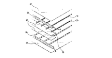
図1aおよび図1bは、本発明の発明者によって先に開発された上記電熱シートの構造を示す斜視図および分解斜視図である。図示されているように、電熱シートSは上側電熱シート51および下側電熱シート52を備えている。両電熱シート51,52の対向面には炭素繊維20が一定間隔で配列されており、炭素繊維20の上には発熱ホイル10が帯のように被せられている。そして、炭素繊維20の端部は、導電性テープである第1,2電極体30,35によって上側および下側の電熱シート51,52の表面に接着・固定されている。そして、第1,2電極体30,35には絶縁ホイル60が接着されている。また、上側及び下側の電熱シート51,52は、上・下炭素繊維20の間隔が約10cmから15cmになるように設定された状態で互いに合致されている。なお、図1aでは、電熱シートSの構造を解りやすく説明するために、上側電熱シート51の短部を部分的に剥がした状態の電熱シートSを示した。
1a and 1b are a perspective view and an exploded perspective view showing the structure of the electric heating sheet previously developed by the inventors of the present invention. As illustrated, the electric heating sheet S includes an upper
このような従来の電熱シートSは、第1,2電極体30,35を通して炭素繊維20に通電させることで炭素繊維20を発熱させると共に炭素繊維20を覆っている発熱ホイル10をも発熱させるものであり、電熱シートSを全体的に迅速に発熱させることができるという長所を備えている。
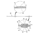
ところで、従来の電熱シートSでは、図1bに図示されるように、第1,2電極体30,35の接触を防止するために必然的に幅の広い絶縁ホイル60を第1,2電極体30,35の上に手作業で付着している。ところが、電熱シートSを熱付着する課程で、絶縁ホイル60の部分の接着剤が硬化し、当該部分の接着剤の接着力が悪くなることがある。この場合、絶縁ホイル60部分に位置する炭素繊維20は、図1cで示したように動くようになるので、互いにショートしてしまうという問題が生ずるおそれがあることが解った。
By the way, in the conventional electric heating sheet S, as shown in FIG. 1B, in order to prevent the first and
また、このような従来の電熱シートでは、上側および下側電熱シート51,52に炭素繊維20を固定させるために、テープタイプの多数の発熱ホイル10を貼り付けているが、この貼り付け作業は容易でなく、現実には一つ一つ手作業で貼り付ける必要があった。また、発熱ホイル10の付着過程において、炭素繊維20の間隔を一定に維持することが難しいという問題がある。間隔を一定に維持できなければ大量の電磁波の発生を抑えることは難しく、間隔を一定に維持しようとすると電熱シートSの大量生産をすることが難しいという問題点が生ずる。
Moreover, in such a conventional electric heating sheet, in order to fix the
本発明は、このような諸問題に鑑みてなされたものであり、炭素繊維などの導電性細長材が堅固に固定された電熱シートを提供すること、そしてこのような電熱シートを量産するための製造方法を提供することを目的としている。 The present invention has been made in view of such problems, and provides an electric heating sheet in which conductive elongated members such as carbon fibers are firmly fixed, and mass production of such an electric heating sheet. The object is to provide a manufacturing method.
上記課題を解決するため、本発明は、以下のような電熱シートを提供する。 In order to solve the above problems, the present invention provides the following electric heating sheet.
請求項1に記載の発明は、相対向して配置される2つのシート(610,620)と、両シート(610,620)の間に並列配置される第1導電部(630)および第2導電部(631)と、前記第1導電部(630)に対して絶縁状態で配置される第3導電部(632)と、絶縁テープ(641)と、当該絶縁テープ(641)の両面に付着した第4導電テープ(643)および第5導電テープ(644)と、当該第4導電テープ(643)および第5導電テープ(644)の各々に付着された電線(645)とで構成され、前記第1導電部(630)と前記第3導電部(632)との間に積層配置される中間部材(640)と、前記第1導電部(630)および前記第4導電テープ(643)の間に挟まれる状態でこれらに接着および圧着されるとともに、前記第1導電部(630)および第2導電部(631)の間に配置されており、両導電部に通電している一群の導電性細長材(C)と、前記第3導電部(632)および第5導電テープ(644)の間に挟まれる状態でこれらに接着および圧着されるとともに、前記第2導電部(631)および第3導電部(632)の間に配置されており、両導電部に通電している他群の導電性細長材(C)と、を備えたことを特徴とする電熱シートである。 The invention according to claim 1 includes two sheets (610, 620) arranged opposite to each other, and a first conductive part (630) and a second conductive part (631) arranged in parallel between the two sheets (610, 620). ), A third conductive portion (632) disposed in an insulated state with respect to the first conductive portion (630), an insulating tape (641), and a fourth conductive material attached to both surfaces of the insulating tape (641). A tape (643) and a fifth conductive tape (644); and an electric wire (645) attached to each of the fourth conductive tape (643) and the fifth conductive tape (644). The intermediate member (640) stacked between the (630) and the third conductive part (632), and the state sandwiched between the first conductive part (630) and the fourth conductive tape (643) Are bonded and pressure-bonded to each other, and are disposed between the first conductive portion (630) and the second conductive portion (631), and a group of conductive strips (C ) And the above Conductive part while being bonded and crimped thereto in a state sandwiched between the (632) and fifth conductive tape (644), disposed between said second conductive portion (631) and the third conductive portion (632) And an electrically conductive sheet comprising another group of conductive elongated members (C) energizing both conductive portions.
請求項2に記載の発明は、前記中間部材(640)は両面テープ(646)を備え、その両面テープ(646)の上面と下面とに前記絶縁テープ(641)が各々付着された請求項1に記載の電熱シートである。 According to a second aspect of the present invention, the intermediate member (640) includes a double-sided tape (646), and the insulating tape (641) is attached to an upper surface and a lower surface of the double-sided tape (646), respectively. It is an electrothermal sheet | seat as described in .
請求項3に記載の発明は、前記導電性細長材は、炭素繊維である請求項1または請求項2に記載の電熱シートである。 The invention according to claim 3 is the electrothermal sheet according to claim 1 or 2 , wherein the conductive elongated material is carbon fiber.
請求項4に記載の発明は、前記両シート(610,620)には、相対向するシート側の面に熱硬化性接着剤が塗布された請求項1〜請求項3のうちいずれか1項に記載の電熱シートである。 The invention according to claim 4 is the invention according to any one of claims 1 to 3 , wherein a thermosetting adhesive is applied to the surfaces of the sheets (610, 620) facing each other. This is an electric heating sheet.
請求項5に記載の発明は、前記絶縁テープは、透明である請求項1〜請求項4のうちいずれか1項に記載の電熱シートである。 The invention according to claim 5 is the electrothermal sheet according to any one of claims 1 to 4 , wherein the insulating tape is transparent.
請求項6に記載の発明は、前記絶縁テープは、その両面に熱硬化性接着剤が塗布された請求項1〜請求項5のうちいずれか1項に記載の電熱シートである。 The invention according to claim 6 is the electrothermal sheet according to any one of claims 1 to 5 , wherein the insulating tape is coated with a thermosetting adhesive on both surfaces thereof .
請求項7に記載の発明は、請求項1から請求項6のいずれか一項に記載の電熱シートであって、前記第1導電部(630)、前記第3導電部(632)および中間部材(640)はその幅が同じであるものである。 The invention according to claim 7 is the electric heating sheet according to any one of claims 1 to 6, wherein the first conductive portion (630), the third conductive portion (632), and the intermediate member (640) has the same width.
請求項8に記載の発明は、2つのシート(610,620)を供給するシート供給工程と、両シート(610,620)の間に導電性細長材(C)を供給する導電性細長材供給工程と、両シート(610,620)を加熱しながら搬送する加熱搬送工程と、搬送される両シート(610,620)のうちの一方のシートに帯状の第1導電体(630)を第1導電体付着工程と、前記一方のシート(610)に帯状の第2導電体(631)を付着し、他方のシート(620)に帯状の第3導電体(632)を付着する第2導電体付着工程と、前記一方のシート(610)の前記第1導電体(630)に、絶縁テープ(641)と、当該絶縁テープ(641)の両面に付着した第4導電テープ(643)および第5導電テープ(644)と、当該第4導電テープ(643)および第5導電テープ(644)の各々に付着された電線(645)とで構成された中間部材(640)を付着する中間部材付着工程と、中間部材付着段階を通過した前記一方のシート(610)と他方のシート(620)を圧着する圧着工程とを有する電熱シートの製造方法である。
The invention described in
請求項9に記載の発明は、2つのシート(610,620)を供給するシート供給工程と、両シート(610,620)の間に、複数の導電性細長材(C) を相互に電気的に絶縁されていると共に並列配置される状態で供給する導電性細長材供給工程と、前記複数の導電性細長材(C)のうち1つ以上の導電性細長材の一端側に電気的に接続されると共に残る導電性細長材の一端側とは電気的に絶縁される帯状の第1導電体(630)を供給する工程と、前記複数の導電性細長材(C)の他端側に電気的に接続する帯状の第2導電体(631)を供給する工程と、前記第1導電部(630)の一端側とは電気的に絶縁される導電性細長材(C)のうち1つ以上の導電性細長材の一端側に電気的に接続される帯状の第3導電体(632)を供給する工程と、絶縁テープ(641)と、当該絶縁テープ(641)の両面に付着した第4導電テープ(643)および第5導電テープ(644)と、当該第4導電テープ(643)および第5導電テープ(644)の各々に付着された電線(645)とで構成された中間部材(640)を、前記第1導電体(630)と前記第3導電体(632)との間に供給する中間部材供給工程と、前記2つのシート(610,620)および両シートの間に供給された部材を熱圧着する熱圧着工程とを備えており、前記シート供給工程、前記導電性細長材供給工程、前記第1導電体(630)を供給する工程、前記第2導電体(631)を供給する工程、前記第3導電体(632)を供給する工程および前記中間部材供給工程が行われる時期は、少なくとも前記熱圧着工程の前である電熱シートの製造方法である。 According to the ninth aspect of the present invention, a plurality of conductive strips (C) are electrically insulated from each other between a sheet supplying step for supplying two sheets (610,620) and both sheets (610,620). A conductive elongated material supplying step that is supplied in a state of being arranged in parallel and electrically connected to one end side of one or more conductive elongated materials among the plurality of conductive elongated materials (C) and remains A step of supplying a strip-shaped first conductor (630) that is electrically insulated from one end side of the conductive elongated member, and an electrical connection to the other end side of the plurality of conductive elongated members (C) The step of supplying the strip-shaped second conductor (631) and one or more conductive elongated members (C) that are electrically insulated from one end of the first conductive portion (630). Supplying a strip-shaped third conductor (632) electrically connected to one end of the material, an insulating tape (641), and a fourth attached to both surfaces of the insulating tape (641) An intermediate member (640 ) composed of a conductive tape (643) and a fifth conductive tape (644), and an electric wire (645) attached to each of the fourth conductive tape (643) and the fifth conductive tape (644). ) Is supplied between the first conductor (630) and the third conductor (632), the two sheets (610, 620) and the member supplied between the two sheets are provided. A step of supplying the first conductor (630), a step of supplying the second conductor (631), and a step of supplying the first conductor (630). The time when the step of supplying the third conductor (632) and the step of supplying the intermediate member are performed is at least the method for manufacturing an electrothermal sheet before the thermocompression bonding step.
請求項10に記載の発明は、請求項8または請求項9に記載の電熱シートの製造方法であって、圧着により得られた電熱シート(600)を一定の大きさに切断する切断工程をさらに有するものである。
Invention of
請求項11に記載の発明は、請求項8から請求項10のいずれか一項に記載の電熱シートの製造方法であって、前記導電性細長材供給工程は、炭素繊維(C)を供給する工程である。 Invention of Claim 11 is a manufacturing method of the electrically heated sheet | seat as described in any one of Claims 8-10, Comprising: The said electroconductive elongate material supply process supplies carbon fiber (C). It is a process.
請求項12に記載の発明は、請求項11に記載の電熱シートの製造方法であって、前記導電性細長材供給工程は、炭素繊維(C)を前記シート(610,620)の両側から供給するものであり、前記炭素繊維(C)は等間隔で配列された状態を維持しながら前記両シート(610,620)の間に供給されるものである。 The invention according to claim 12 is the method for manufacturing an electric heating sheet according to claim 11, wherein the conductive elongated material supplying step supplies carbon fiber (C) from both sides of the sheet (610, 620). The carbon fibers (C) are supplied between the two sheets (610, 620) while maintaining a state of being arranged at equal intervals.
請求項1から請求項7のいずれか一項に記載の発明によれば、導電性細長材は堅固に固定されており、導電性細長材どうしのショートが確実に防止されると共に電磁波の発生が最小限に抑制される。また、電気安全性や耐久性などが向上する。また、導電性細長材の配列や間隔を一定に維持できるので、電熱シート使用時における電磁波の発生を著しく減少させることができ、電熱シートの信頼性が著しく向上する。 According to the invention described in any one of claims 1 to 7, the conductive elongated member is firmly fixed, and short-circuiting between the conductive elongated members is surely prevented and generation of electromagnetic waves is prevented. Minimized. In addition, electrical safety and durability are improved. In addition, since the arrangement and interval of the conductive strips can be kept constant, the generation of electromagnetic waves when using the electric heating sheet can be remarkably reduced, and the reliability of the electric heating sheet is remarkably improved.
請求項7から請求項11のいずれか一項に記載の発明では、導電性細長材を供給している。この供給方法は、比較的高速で導電性細長材を供給できる方法であり、量産に適した供給方法である。またこのようにして導電性細長材を供給すると、導電性細長材は張力が加わった状態で供給されることとなり、この張力によって導電性細長材は安定した位置に供給される。その結果、導電性細長材の間隔が一定に維持され、導電性細長材どうしのショートが確実に防止されると共に、電磁波の発生が最小限に抑制される。また、導電性細長材の配列や間隔が一定に維持された電熱シートを製造できるので、電熱シート使用時における電磁波の発生を著しく減少させることができ、より信頼性に優れる電熱シートを製造できることになる。 In the invention according to any one of claims 7 to 11, a conductive elongated material is supplied. This supply method is a method that can supply the conductive elongated material at a relatively high speed, and is a supply method suitable for mass production. When the conductive elongated member is supplied in this way, the conductive elongated member is supplied in a state where tension is applied, and the conductive elongated member is supplied to a stable position by this tension. As a result, the distance between the conductive elongated members is maintained constant, and short-circuiting between the conductive elongated members is surely prevented, and generation of electromagnetic waves is minimized. In addition, since it is possible to manufacture an electric heating sheet in which the arrangement and interval of the conductive strips are maintained constant, generation of electromagnetic waves when using the electric heating sheet can be significantly reduced, and an electric heating sheet with higher reliability can be manufactured. Become.
以下、本発明に係る電熱シート(電熱積層シート)は、その製造方法および製造装置について詳細に説明する。 Hereinafter, the electrothermal sheet (electrothermal laminate sheet) according to the present invention will be described in detail with respect to the production method and production apparatus.
本発明に係る電熱シートは、相対向して配置される2つのシートと、両シートの間に並列配置される第1導電部および第2導電部と、当該第1導電部および第2導電部の間に配置されており、両導電部に通電している導電性細長材と、前記第1導電部に対して絶縁状態で配置される第3導電部と、前記第2導電部および第3導電部の間に配置されており、両導電部に通電している導電性細長材とを備えるものである。 The electrothermal sheet according to the present invention includes two sheets arranged opposite to each other, a first conductive part and a second conductive part arranged in parallel between the two sheets, and the first conductive part and the second conductive part. A conductive elongated member that is energized between the two conductive portions, a third conductive portion that is insulated from the first conductive portion, the second conductive portion, and the third conductive portion. It is arrange | positioned between the electroconductive parts, and is provided with the electroconductive elongate material which has supplied with electricity to both the electroconductive parts.
導電性細長材は複数配置される。各導電性細長材は、両シートの間に、相互に電気的に絶縁された状態で並列配置される。そして、第1導電部を、1つ以上の導電性細長材(以下、一群の導電性細長材とも称する)の一端側に電気的に接続し、残る導電性細長材(以下、他群の導電性細長材とも称する)の一端側とは電気的に絶縁させる。一方、第3導電部を、前記他群の導電性細長材の一端側に電気的に接続し、前記一群の導電性細長材の一端側とは電気的に絶縁させる。さらに、第2導電部を、各導電性細長材の他端側と電気的に接続する。また、前記一群の導電性細長材の各導電性細長材を、前記他群の導電性細長材に隣接配置する。そして、前記2つのシート、両シートの間に配置される導電性細長材、導電部を、接着により一体化する。 A plurality of conductive strips are arranged. The respective conductive elongated members are arranged in parallel between the two sheets while being electrically insulated from each other. The first conductive portion is electrically connected to one end of one or more conductive elongated members (hereinafter also referred to as a group of conductive elongated members), and the remaining conductive elongated members (hereinafter referred to as other groups of conductive members). It is also electrically insulated from one end side (also referred to as an elongated material). On the other hand, the third conductive portion is electrically connected to one end side of the other group of conductive elongated members, and is electrically insulated from one end side of the group of conductive elongated members. Furthermore, the second conductive portion is electrically connected to the other end side of each conductive elongated member. Further, each conductive elongated member of the group of conductive elongated members is disposed adjacent to the other group of conductive elongated members. Then, the two sheets, the elongated conductive material disposed between the two sheets, and the conductive portion are integrated by bonding.
前記第1導電部と第3導電部の配置構成としては、その間に中間部材を介して積層配置する構成が好ましい。この場合、中間部材も、前記2つのシート等に接着により一体化される。また、中間部材を、前記複数の導電性細長材と交差する状態に配置し、かつ、中間部材を前記一群の導電性細長材と前記他群の導電性細長材で両側から挟む配置にすることが好ましい。 As an arrangement configuration of the first conductive portion and the third conductive portion, a configuration in which the first conductive portion and the third conductive portion are stacked via an intermediate member therebetween is preferable. In this case, the intermediate member is also integrated with the two sheets by adhesion. Further, the intermediate member is disposed so as to intersect with the plurality of conductive elongated members, and the intermediate member is disposed between both sides of the group of conductive elongated members and the other group of conductive elongated members. Is preferred.
前記導電性細長材としては、金属製の線材、導電性の糸状材などを挙げることができるが、炭素繊維が好ましい。前記中間部材は、絶縁テープと、当該絶縁テープの両面に付着した第4導電テープおよび第5導電テープと、当該第4導電テープおよび第5導電テープの外面すなわち前記絶縁テープに付着される面と反対の面に各々付着された電線とで構成されているものでもよい。また、前記中間部材は、両面テープと、当該両面テープの上面と下面に各々付着した絶縁テープと、各絶縁テープの外面(上面や底面)に各々付着された第4導電テープおよび第5導電テープと、当該第4導電テープおよび第5導電テープの各々に付着された電線とで構成されているものでもよい。前記絶縁テープは透明であるものでもよい。前記第1導電部、前記第3導電部および中間部材はその幅が同じであるものが好ましい。 Examples of the conductive elongated material include metal wires and conductive thread-like materials, and carbon fibers are preferable. The intermediate member includes an insulating tape, a fourth conductive tape and a fifth conductive tape attached to both surfaces of the insulating tape, and an outer surface of the fourth conductive tape and the fifth conductive tape, that is, a surface attached to the insulating tape. It may be composed of electric wires attached to opposite surfaces. In addition, the intermediate member includes a double-sided tape, an insulating tape attached to the top and bottom surfaces of the double-sided tape, and a fourth conductive tape and a fifth conductive tape attached to the outer surfaces (upper surface and bottom surface) of each insulating tape. And an electric wire attached to each of the fourth conductive tape and the fifth conductive tape. The insulating tape may be transparent. The first conductive part, the third conductive part, and the intermediate member preferably have the same width.
ここで、前記一群の導電性細長材は、2以上であり、一群の第1導電性細長材の各導電性細長材(以下、第1導電性細長材とも称する)に隣接して、前記他群の導電性細長材のいずれかの導電性細長材(以下、第2導電性細長材とも称する)が配置されており、各第1導電性細長材と当該第1導電性細長材に隣接して並列配置される第2導電性細長材との間隔は、等間隔であることが好ましい。前記導電性細長材は、炭素繊維であることが好ましい。 Here, the group of conductive elongated members is two or more, and adjacent to each conductive elongated member of the group of first conductive elongated members (hereinafter also referred to as a first conductive elongated member), the other A conductive elongated member (hereinafter also referred to as a second conductive elongated member) of the group of conductive elongated members is disposed, and is adjacent to each first conductive elongated member and the first conductive elongated member. It is preferable that the intervals between the second conductive elongated members arranged in parallel are equal intervals. The conductive elongated material is preferably carbon fiber.
前記中間部材と交差する導電性細長材のうち、第1導電性細長材は、第1導電部と中間部材とに挟まれており、第2導電性細長材は、第3導電部と中間部材とに挟まれていることが好ましい。 Of the conductive elongated members that intersect the intermediate member, the first conductive elongated member is sandwiched between the first conductive portion and the intermediate member, and the second conductive elongated member is the third conductive portion and the intermediate member. It is preferable to be sandwiched between.
また、前記第1導電性細長材は2以上であり、当該第1導電性細長材と前記第2導電性細長材とが交互に並列配置されていることが好ましい。この場合、並列配置される複数の前記導電性細長材は、等間隔に配置されているか、または、密の間隔と疎の間隔とが交互に出現するように配置されていることが好ましい。後者の場合、少なくとも疎の間隔は一定の間隔であることが好ましい。 In addition, it is preferable that the number of the first conductive elongated members is two or more, and the first conductive elongated members and the second conductive elongated members are alternately arranged in parallel. In this case, it is preferable that the plurality of conductive strips arranged in parallel are arranged at equal intervals, or arranged so that dense intervals and sparse intervals appear alternately. In the latter case, it is preferable that at least the sparse intervals are constant.
前記のシート、導電部および中間部材としては、可撓性を有するものが好ましい。 As said sheet | seat, an electroconductive part, and an intermediate member, what has flexibility is preferable.
シートとしては、紙製シート、布製シート、ビニルなどの合成樹脂製シートやフィルムなどが好ましく、さらにいえば、非伸縮性のものが好ましい。伸縮がなければ、炭素繊維相互間の距離が一定に維持され、電磁波がより確実に相殺され、電磁波の発生が抑制される。そして、炭素繊維の断線が防止され、炭素繊維相互の接触によるショートの発生や局部的な過加熱などの発生が防止される。また、いわゆるラミネートなどの熱圧着でシートどうしを接着する場合、シートとしてはラミネート可能なフィルムなどが好ましい。なお、ここでいう伸縮性とは、熱圧着を用いる場合、熱圧着後の伸縮性のことである。シートとしては、相対向するシート側の面に熱硬化性接着剤が塗布されているものが好ましい。前記2つのシートのうち少なくともいずれか一方は、透明など、両シート間に配置された導電性細長材を視認可能にする光透過性を有することが好ましい。 The sheet is preferably a paper sheet, a cloth sheet, a sheet made of synthetic resin such as vinyl, or a film, and more preferably a non-stretchable sheet. Without expansion and contraction, the distance between the carbon fibers is kept constant, electromagnetic waves are more reliably offset, and generation of electromagnetic waves is suppressed. And the disconnection of carbon fibers is prevented, and the occurrence of short circuit or local overheating due to contact between carbon fibers is prevented. Further, when the sheets are bonded to each other by thermocompression bonding such as so-called lamination, a film that can be laminated is preferable as the sheet. Here, the term “stretchability” as used herein refers to the stretchability after thermocompression when thermocompression bonding is used. As a sheet | seat, the thing by which the thermosetting adhesive agent is apply | coated to the surface of the sheet | seat side which opposes is preferable. It is preferable that at least one of the two sheets has a light transmission property such that the conductive elongated member disposed between the two sheets can be visually recognized, such as a transparent sheet.
各導電部としては、いわゆる導電テープが好ましい。例えば、アルミニウム箔、銅箔、アルミニウムや銅等の導電性金属あるいはその他の導電性材料を含む可撓性を有するテープ材を挙げることができる。 Each conductive part is preferably a so-called conductive tape. For example, a flexible tape material including an aluminum foil, a copper foil, a conductive metal such as aluminum or copper, or another conductive material can be given.
中間部材としては、可撓性を有する絶縁テープが好ましい。また、中間部材は透明など光透過性を有するものでもよい。絶縁テープとしては、その両面に熱硬化性接着剤が塗布されているものが好ましい。絶縁テープの好ましい例としては、たとえば、いわゆる両面テープ(あるいは両面粘着テープ)を挙げることができる。そして、両面テープの両面に付着された各絶縁テープは、一面に熱硬化性接着剤が塗布されているものが好ましい。そして、絶縁テープ、両面テープとしては、透明など光透過性を有する素材が好ましい。さらに、導電性細長材としては準1次元繊維半導体が好ましい。 As the intermediate member, a flexible insulating tape is preferable. Further, the intermediate member may be light transmissive such as transparent. As the insulating tape, one having a thermosetting adhesive applied to both sides thereof is preferable. As a preferable example of the insulating tape, for example, a so-called double-sided tape (or double-sided adhesive tape) can be mentioned. And as for each insulating tape adhering to both surfaces of the double-sided tape, what the thermosetting adhesive agent was apply | coated to one side is preferable. And as an insulating tape and a double-sided tape, the transparent material, such as transparency, is preferable. Furthermore, a quasi-one-dimensional fiber semiconductor is preferable as the conductive elongated material.
各導電部および中間部材としては、炭素繊維などの導電性細長材が多数ある場合、帯状材であることが好ましい。そして、各導電部および中間部材は同幅であることがより好ましい。 Each conductive portion and intermediate member is preferably a strip-shaped material when there are a large number of conductive elongated materials such as carbon fibers. And it is more preferable that each conductive part and the intermediate member have the same width.
なお、電熱シートは、上部シートと、下部シートと、上記の上部シートの底面と下部シートの上面に付着される第1,2,3導電テープと、第1,3導電テープの間に接着される中間部材と、第1導電テープと中間部材の間および第3導電テープと中間部材の間に各々設置されるカーボン糸Cで構成されていることを特徴とする電熱シートであるということもできる。 The electrothermal sheet is bonded between the upper sheet, the lower sheet, the first, second and third conductive tapes attached to the bottom surface of the upper sheet and the upper surface of the lower sheet, and the first and third conductive tapes. It can also be said that it is an electric heating sheet characterized by comprising an intermediate member, and carbon yarn C installed between the first conductive tape and the intermediate member and between the third conductive tape and the intermediate member. .
本発明に係る電熱シートの製造方法は、2つのシート(610,620)を供給するシート供給工程と、両シート(610,620)の間に導電性細長材(C)を供給する導電性細長材供給工程と、両シート(610,620)を加熱しながら搬送する加熱搬送工程と、搬送される両シート(610,620)のうちの一方のシートに帯状の第1導電体(630)を付着する第1導電体付着工程と、前記一方のシート(610)に帯状の第2導電体(631)を付着し、他方のシート(620)に帯状の第3導電体(632)を付着する第2導電体付着工程と、前記一方のシート(610)の前記第1導電体(630)に、絶縁のための中間部材(640)を付着する中間部材付着工程と、中間部材付着段階を通過した前記一方のシート(610)と他方のシート(620)を圧着する圧着工程とを有するものである。 The method for manufacturing an electrothermal sheet according to the present invention includes a sheet supplying step for supplying two sheets (610, 620), and a conductive elongated material supplying step for supplying a conductive elongated material (C) between both sheets (610, 620). A heating and conveying step of conveying both sheets (610, 620) while heating, and a first conductor adhering step of adhering a belt-shaped first conductor (630) to one of the conveyed sheets (610, 620) A second conductor adhering step of adhering a band-shaped second conductor (631) to the one sheet (610) and adhering a band-shaped third conductor (632) to the other sheet (620); An intermediate member attaching step for attaching an intermediate member (640) for insulation to the first conductor (630) of the one sheet (610), and the one sheet (610) that has passed through the intermediate member attaching step. And a crimping step of crimping the other sheet (620).
また、本発明に係る電熱シートの製造方法は、2つのシート(610,620)を供給するシート供給工程と、両シート(610,620)の間に、複数の導電性細長材(C) を相互に電気的に絶縁されていると共に並列配置される状態で供給する導電性細長材供給工程と、前記複数の導電性細長材(C)のうち1つ以上の導電性細長材の一端側に電気的に接続されると共に残る導電性細長材の一端側とは電気的に絶縁される帯状の第1導電体(630)を供給する工程と、前記複数の導電性細長材(C)の他端側に電気的に接続する帯状の第2導電体(631)を供給する工程と、前記第1導電部(630)の一端側とは電気的に絶縁される導電性細長材(C)のうち1つ以上の導電性細長材の一端側に電気的に接続される帯状の第3導電体(632)を供給する工程と、前記第1導電体(630)と前記第3導電体(632)とを絶縁する中間部材(640)を、前記第1導電体(630)と前記第3導電体(632)との間に供給する中間部材供給工程と、前記2つのシート(610,620)および両シートの間に供給された部材を熱圧着する熱圧着工程とを備えており、前記シート供給工程、前記導電性細長材供給工程、前記第1導電体(630)を供給する工程、前記第2導電体(631)を供給する工程、前記第3導電体(632)を供給する工程および前記中間部材供給工程が行われる時期は、少なくとも前記熱圧着工程の前であるものである。 In addition, the method for producing an electrothermal sheet according to the present invention includes a sheet supply step for supplying two sheets (610, 620), and a plurality of conductive elongated members (C) electrically connected to each other between the sheets (610, 620). Electrically conductive elongated material supplying step that is insulated and supplied in parallel, and electrically connected to one end side of one or more conductive elongated materials among the plurality of conductive elongated materials (C) And a step of supplying a strip-shaped first conductor (630) that is electrically insulated from one end side of the remaining conductive strip, and an electrical connection to the other end of the plurality of conductive strips (C). One or more of the conductive strips (C) that are electrically insulated from the step of supplying the strip-shaped second conductor (631) to be electrically connected and one end of the first conductive portion (630) Supplying a strip-shaped third conductor (632) electrically connected to one end of the conductive elongated member, the first conductor (630) and the third conductor (632) An intermediate member supplying step of supplying an intermediate member (640) that insulates between the first conductor (630) and the third conductor (632), the two sheets (610, 620), and both sheets A thermocompression bonding step of thermocompression bonding the member supplied between the sheet, the sheet supply step, the conductive elongated material supply step, the first conductor (630) supply step, the second conductivity The time when the step of supplying the body (631), the step of supplying the third conductor (632) and the step of supplying the intermediate member are performed is at least before the thermocompression bonding step.
なお、前記シート供給工程、前記導電性細長材供給工程、前記第1導電体(630)を供給する工程、前記第2導電体(631)を供給する工程、前記第3導電体(632)を供給する工程および前記中間部材供給工程の順番は問わないが、上記の記載順は順番として好ましい形態の1つである。 The sheet supply step, the conductive elongated material supply step, the first conductor (630) supply step, the second conductor (631) supply step, and the third conductor (632) include The order of the supplying step and the intermediate member supplying step is not limited, but the above described order is one of the preferred forms as the order.
また、前記導電性細長材供給工程、前記第1導電体(630)を供給する工程、前記第2導電体(631)を供給する工程、前記第3導電体(632)を供給する工程および前記中間部材供給工程が行われる時期は、少なくとも前記シート供給工程の後であると共に前記熱圧着工程の前であることが好ましい。 A step of supplying the conductive elongated material; a step of supplying the first conductor (630); a step of supplying the second conductor (631); a step of supplying the third conductor (632); It is preferable that the intermediate member supplying step is performed at least after the sheet supplying step and before the thermocompression bonding step.
本発明に係る製造方法は、両シートおよび炭素繊維などの導電性細長材を自動供給して、これらを加熱圧着するものである。この場合、各導電体や中間部材の供給やこれらの付着を一定の位置に固定された供給手段や付着手段によって反復的に行うことができる。したがって、電熱シートを量産する方法として好適である。両シートおよび炭素繊維などの導電性細長材の供給方法としては連続供給が好ましい。これにより電熱シートを連続的に量産できる。熱圧着工程としては、いわゆるラミネート工程を挙げることができる。 In the manufacturing method according to the present invention, conductive elongated materials such as both sheets and carbon fibers are automatically supplied, and these are thermocompression bonded. In this case, the supply of each conductor and intermediate member and their attachment can be performed repeatedly by the supply means and attachment means fixed at a fixed position. Therefore, it is suitable as a method for mass-producing electric heating sheets. As a method for supplying the conductive strips such as both sheets and carbon fiber, continuous supply is preferable. Thereby, an electrothermal sheet can be mass-produced continuously. Examples of the thermocompression bonding process include a so-called laminating process.
このように一定の位置で各導電テープなどの導電体や中間部材を供給したり付着したりすることができれば、相互の位置関係を容易かつ正確に位置決めした状態で供給したり付着(圧着)したりできるので作業効率が向上する。また、これらの作業の自動化が容易であり、これらの作業を自動的に行う供給手段や付着手段を用いて行うことができる。このようにすれば、さらに作業効率が向上する。また、各導電テープなどの導電体と中間部材とを正確に位置決めできれば、いわゆるショートの発生がより確実に防止され、導電性の強化を通じて電気の安全性も向上する。 In this way, if conductors such as each conductive tape and intermediate members can be supplied or adhered at a certain position, they can be supplied or adhered (crimped) with their mutual positional relationship easily and accurately positioned. Work efficiency is improved. Also, these operations can be easily automated, and can be performed using supply means and attachment means that automatically perform these operations. In this way, work efficiency is further improved. In addition, if the conductor such as each conductive tape and the intermediate member can be accurately positioned, the occurrence of so-called short-circuits can be prevented more reliably, and the safety of electricity can be improved through enhanced conductivity.
ここで、圧着により得られた電熱シート(600)を一定の大きさに切断する切断工程をさらに有するものでもよい。前記導電性細長材供給工程は炭素繊維(C)を供給する工程であってもよい。両シートを供給する工程は両シートを加熱しながら搬送する加熱搬送工程でもよい。炭素繊維などの導電性細長材を供給する導電性細長材供給工程は、等間隔で配列される状態で導電性細長材を両シートの間に供給する工程でも良い。 Here, you may further have the cutting process which cut | disconnects the electrothermal sheet | seat (600) obtained by crimping | bonding to a fixed magnitude | size. The conductive elongated material supplying step may be a step of supplying carbon fiber (C). The step of supplying both sheets may be a heating and conveying step of conveying both sheets while heating. The conductive elongated material supplying step of supplying a conductive elongated material such as carbon fiber may be a step of supplying the conductive elongated material between both sheets in a state of being arranged at equal intervals.
前記導電性細長材供給工程は、炭素繊維を前記シートの両側から供給するものであり、前記炭素繊維は等間隔で配列された状態を維持しながら前記両シートの間に供給されるものが好ましい。 In the conductive elongated material supplying step, carbon fibers are supplied from both sides of the sheet, and the carbon fibers are preferably supplied between the two sheets while maintaining a state of being arranged at equal intervals. .
本発明に係る製造方法の実施形態では、両シートおよび各導電体によって炭素繊維などの導電性細長材を両側から挟むようにして圧着し、固定するので、炭素繊維を堅固に固定することができ、導電性細長材間のショートが画期的に防止される。これにより、製品の電気的な安全性が著しく向上するという有用な効果がある。 In the embodiment of the manufacturing method according to the present invention, since the conductive elongated member such as carbon fiber is sandwiched from both sides and fixed by both sheets and each conductor, the carbon fiber can be firmly fixed and conductive. A short circuit between the elongated strips is epoch-making. Thereby, there is a useful effect that the electrical safety of the product is remarkably improved.
電熱シート製造装置の装置本体の両側方向から炭素繊維などの導電性細長材を供給してもよい。このようにすると、電熱シートの製造に必要なスペースすなわち製造装置の設置スペースを小さくすることができるという有用な効果がある。また、等間隔の配列など一定間隔の配列を維持しながら炭素繊維などの導電性細長材を供給することで、作業者の作業空間を確保できるという有用な効果がある。 You may supply electroconductive elongate materials, such as carbon fiber, from the both-sides direction of the apparatus main body of an electrothermal sheet manufacturing apparatus. If it does in this way, there exists a useful effect that the space required for manufacture of an electrothermal sheet, ie, the installation space of a manufacturing apparatus, can be made small. In addition, there is a useful effect that a working space for an operator can be secured by supplying a conductive elongated material such as carbon fiber while maintaining an arrangement with a constant interval such as an arrangement with an equal interval.
導電性細長材供給工程は、3以上の導電性細長材を供給する工程であると共に、後に前記第1導電性細長材として用いられる導電性細長材に隣接して、後に第2導電性細長材として用いられる導電性細長材が隣接配置される配列ようになっており、各第1導電性細長材と当該第1導電性細長材に隣接配置される第2導電性細長材との間隔は等間隔であるように供給してもよい。 The conductive elongated material supplying step is a step of supplying three or more conductive elongated materials, and is adjacent to the conductive elongated material that will be used later as the first conductive elongated material, and later the second conductive elongated material. The conductive elongated members used as the arrangement are arranged adjacent to each other, and the distance between each first conductive elongated member and the second conductive elongated member arranged adjacent to the first conductive elongated member is equal. You may supply so that it may be a space | interval.
電熱シートの製造装置としては、連続供給される2つのシートの供給元であるシート供給ユニットと、両シートの間に連続供給される複数の炭素繊維などの導電性細長材の供給元である導電性細長材ユニットと、連続供給される複数の導電性細長材を並列配置させる配列手段と、前記複数の導電性細長材のうち1つ以上の導電性細長材の一端側に電気的に接続されると共に残る導電性細長材の一端側とは電気的に絶縁される帯状の第1導電体を前記2つのシートの一方に貼り付ける第1付着手段と、前記複数の導電性細長材の他端側に電気的に接続される帯状の第2導電体を前記2つのシートのいずれかに貼り付ける第2付着手段と、前記第1導電部(630)の一端側とは電気的に絶縁される導電性細長材のうち1つ以上の導電性細長材の一端側に電気的に接続される帯状の第3導電体を他方のシートに貼り付ける第3付着手段と、前記第1導電体(630)と前記第3導電体とを絶縁する中間部材を前記第1導電体と前記第3導電体のいずれかに貼り付ける中間部材付着手段と、前記2つのシートおよび両シートの間に供給された部材を加熱する加熱手段および加圧する加圧手段を有しており、これらを熱圧着する熱圧着手段とを備えている電熱シートの製造装置を挙げることができる。 The electrothermal sheet manufacturing apparatus includes a sheet supply unit that is a supply source of two sheets that are continuously supplied, and a conductive source that is a supply source of conductive strips such as a plurality of carbon fibers that are continuously supplied between the two sheets. An electrically conductive elongated member unit, an array means for arranging a plurality of continuously supplied conductive elongated members in parallel, and one end side of one or more conductive elongated members of the plurality of electrically conductive elongated members. And a first adhering means for affixing to one of the two sheets a strip-shaped first conductor that is electrically insulated from one end of the remaining conductive strip, and the other ends of the plurality of conductive strips The second attaching means for attaching the band-like second conductor electrically connected to the side to one of the two sheets is electrically insulated from one end side of the first conductive portion (630). One end side of one or more conductive strips among the conductive strips A third adhering means for affixing an electrically connected strip-shaped third conductor to the other sheet, and an intermediate member that insulates the first conductor (630) from the third conductor. An intermediate member adhering means to be attached to any of the body and the third conductor, a heating means for heating the two sheets and a member supplied between the two sheets, and a pressurizing means for pressurizing, An electrothermal sheet manufacturing apparatus provided with thermocompression bonding means for thermocompression bonding these can be mentioned.
以下、本発明に係る電熱シート、その製造方法およびその製造装置の実施形態について図面を用いて詳細に説明する。 Hereinafter, embodiments of an electric heating sheet, a manufacturing method thereof, and a manufacturing apparatus thereof according to the present invention will be described in detail with reference to the drawings.
まず、電熱シートの製造方法について図面を参照しながら、各工程を段階別に区分して説明する。 First, a process for producing an electric heating sheet will be described by dividing each process step by step with reference to the drawings.
図2は、本発明に係る実施形態の電熱シート製造方法の工程の流れを示すフローチャート図であり、図5aから図5fは、電熱シートの製造過程の各工程を説明するための電熱シート製造装置を示す概略図である。 FIG. 2 is a flowchart showing the flow of steps of the method for manufacturing an electric heating sheet according to the embodiment of the present invention, and FIGS. 5a to 5f are electric heating sheet manufacturing apparatuses for explaining each step of the electric heating sheet manufacturing process. FIG.
図示されるように、本発明に係る実施形態の電熱シートの製造方法は、段階ごとに大きく区分すると、シート供給工程、炭素繊維供給工程、加熱搬送工程、1次導電テープ付着工程、2次導電テープ付着工程、中間部材付着工程、圧着工程および切断工程を有する。以下、各工程について説明する。 As shown in the drawing, the method for manufacturing an electrothermal sheet according to the embodiment of the present invention is roughly divided into stages, a sheet supplying process, a carbon fiber supplying process, a heating and conveying process, a primary conductive tape attaching process, and a secondary conductive process. It has a tape adhesion process, an intermediate member adhesion process, a crimping process, and a cutting process. Hereinafter, each step will be described.
まず、シート供給工程は、図3、図5aに示されるように、上部シート610と下部シート620を供給する段階である。電熱シート製造装置100は、その本体200の前方の上側および下側に、予め設置された上部シートリール210と下部シートリール220を備えており、上部シートリール210から上部シート610が対応する加熱移送台400の方に連続供給され、下部シートリール220から下部シート620が、対応する加熱移送台400の方に連続供給されるようになっている。なお、ここでいう前方とは図3では紙面に向かって右側であり、図5aでは、紙面に向かって左側である。
First, the sheet supply process is a stage in which an
炭素繊維供給工程は、図3、図4および図5aで示されるように、上部シート610と下部シート620との間に配置される炭素繊維Cを供給する段階である。この炭素繊維Cは、サイドプレート300に設置された多数の案内リング350を通じて本体200の側面側から供給され、クロスバー310に設置された多数の案内リング350を通じて一定な間隔で円滑に、配列・供給されるのである。なお、炭素繊維の種類は、発熱量、電熱シートの大きさ、電源出力など、製造する電熱シートの仕様に応じて適宜選択されるものである。
The carbon fiber supply step is a step of supplying carbon fibers C disposed between the
加熱搬送工程は、図5aで示されるように、上部シート610と下部シート620を加熱しながら、搬送し移送する段階である。上部シート610と下部シート620は、各々の加熱移送台400の表面に沿って移送される過程で各々の加熱移送台400から熱伝導されて加熱する。したがって、上部シート610と下部シート620は合成樹脂材質の特性上、加熱移送台400から加熱されることで圧着が容易にできるように柔らかい状態に変わり、上部シート610および下部シート620の一面すなわちお互いに対向している内側面に塗布された熱硬化性接着剤は加熱によって接着性を持つ状態になる。
The heating and conveying step is a step of conveying and transferring the
1次導電テープ付着工程は、図5bで示されるように、加熱移送台400に沿って移送される上部シート610に、1次段階として第1導電テープ630を付着する段階である。図7に示されるように、第1導電テープ630は、加熱移送台400の上面部分に位置している上部シート610に横長の状態で貼り付けなどによって付着される。そして、1次段階として付着する第1導電テープ630は、電源に接続される部分であり、陽極(または陰極)の電流を供給する電極板の役割をすることになる。
The primary conductive tape attaching step is a step of attaching the first
2次導電テープ付着工程は、図5cで示されるように、第1導電テープ630の付着が行われた後、若干のギャップG(図7参照)をおいて上部シート610に第2導電テープ631を付着し、下部シート620には第3導電テープ632を付着する段階である。
5c, after the first
第2導電テープ631は、上部シート610と下部シート620の間に内蔵されている全て炭素繊維Cを電気的に連結する役割をする。第3導電テープ632は、電源に接続される部分であり、陽極(または陰極)の電流を供給する電極板の役割をすることになる。そして、第1,2導電テープ630,631の間のギャップGは完成された電熱シート600の切断のための余裕部分になる。
The second
中間部材付着工程は、図5dで示されるように、上部シート610に付着された第1導電テープ630に、中間部材640を付着する段階である。この中間部材640は、図6で示されるように、両面に熱硬化性接着剤が塗布された絶縁テープ641と、この絶縁テープ641の両面に付着される第4,5導電テープ643,644と、第4導電テープ643の上面と第5導電テープ644の下面に付着された電線645で構成されるものである。したがって、この中間部材付着工程にて、第1導電テープに中間部材640を貼り付けなどによって付着するために、上述のような構成の中間部材640を前もって用意しておく。このような中間部材640を第1導電テープ630に貼り付けなどによって付着すると、中間部材640を構成する第4,5導電テープ643,644は、以降の搬送過程において、上部シート610と下部シート620の第1,3導電テープ630,632の位置と一致する位置に配置されと共に各々接着される。
The intermediate member attaching step is a step of attaching the
一方、中間部材640としては、図6で示されているもの以外にも種々のものが考えられる。たとえば、図8で示されるように、両面テープ646の上面と下面に各々付着されて一面に熱硬化性接着剤が塗布された絶縁テープ642と、このような絶縁テープ642の上面と下面に各々付着される第4,5導電テープ643,644と、第4導電テープ643の上面と第5導電テープ644の底面に付着された電線645で構成される中間部材640を使用することも可能である。
On the other hand, various
また、上記した中間部材640を構成する絶縁テープ641や第4,5導電テープ643,644の幅は、図6で示されるように、上記した第1,3導電テープ630,632と同じであることが望ましいが、絶縁テープ641や第4,5導電テープ643,644の幅が第1,3導電テープ630,632の幅より広いもの、特に若干広いものを使用することも可能である。そして、図9で示されるように、絶縁テープ641や第4,5導電テープ643,644の中でも特に絶縁テープ641の幅が第1,3導電テープ630,632の幅より広いもの、特に若干広いものを使用することも可能である。
Further, the widths of the insulating
圧着工程は、図5eで示されるように、上記の色々な工程を終えた上部シート610と下部シート620を圧着する段階である。このような圧着段階を通して上部シート610、下部シート620、第1,2,3導電テープ630,631,632、中間部材640、炭素繊維Cを一体に圧着することになる。このように、本実施形態の電熱シートは、従来の電熱シートで炭素繊維の上に被せていた発熱ホイル10を用いておらず、より簡素な構造になっている。
As shown in FIG. 5e, the crimping process is a stage in which the
切断工程は、圧着が完了した電熱シート600を図示されていない通常の切断機やはさみなどを使って一定の大きさで切断する段階である(図5f参照)。切断工程では、図7に示されるギャップG部分を切断することになる。
The cutting step is a step of cutting the
このように本発明における電熱シートの製造方法は、上部シート610と下部シート620、そして炭素繊維Cが連続的に自動供給され、上部シート610と下部シート620が加熱移送台400によって加熱されながら自動的に移送される。したがって、上・下部シート610,620と第1,2,3導電テープ630,631,632および中間部材640が自動的に一致させながら圧着されるので電熱シート600の連続生産が可能になり、不良率も大きく減ることになる。
As described above, in the method for manufacturing an electrothermal sheet according to the present invention, the
また、本発明における電熱シートの製造方法によれば、加熱移送台400の所定の位置で作業者が反復的に第1,2,3導電テープ630,631,632を付着する作業だけで第1,2,3導電テープ630,631,632、中間部材640、炭素繊維Cは、正確に一致する状態で接着されることになる。したがって、作業者はより簡単に電熱シート600の生産作業を行うことができるので電熱シート600の生産量も増えることになる。
In addition, according to the method for manufacturing an electrothermal sheet in the present invention, the first and second
しかも、本発明における電熱シートの製造方法では、サイドプレート300とクロスバー310の案内リング350を通して多数の炭素繊維Cを一定の間隔で正確かつ連続的に供給している。したがって、図7で示されるように、炭素繊維Cの一定な配列ができるので高品質の電熱シート600を生産することできるし、事前に設定された間隔で配列された炭素繊維C同士は互いに電磁波を相殺させるので全体的に電熱シート600の電磁波を著しく減少させることができる。
In addition, in the method for manufacturing an electric heating sheet according to the present invention, a large number of carbon fibers C are supplied accurately and continuously at regular intervals through the
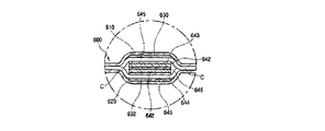
一方、図6は、上記の電熱シートの製造方法を通して生産された電熱シート600の構造を図示した拡大断面図である。図示されるように、電熱シート600は、概略的には、上部シート610および下部シート620、第1,2,3導電テープ630,631,632、中間部材640、炭素繊維Cで構成される。
On the other hand, FIG. 6 is an enlarged cross-sectional view illustrating the structure of the
まず、上部シート610と下部シート620は、いわゆる外皮の役割をするもので透明性の合成樹脂フィルムを使うことが望ましい。また、上部シート610の底面(内面すなわち下部シート620側の面)と下部シート620の上面(内面すなわち上部シート610側の面)には、熱圧着の際、熱硬化性接着剤が塗布されており、加熱および加圧によって上部シート610と下部シート620とがより確実に一体に圧着される。
First, the
第1,3導電テープ630,632は、上部シート610と下部シート620の間に内蔵されている炭素繊維Cに陽極(または陰極)の電流を印加する導電板の役割をするものである。第1,2導電テープ630,631は、ギャップGとして示されている間隔をおいて、上部シート610の底面に付着される。また、第3導電テープ632は、上記した第1導電テープ630の直下方に位置するよう下部シート620の上面に付着される。
The first and third
中間部材640は、上記した第1,3導電テープ630,632の間に付着されるものであり、絶縁機能を担うものである。本発明では、この中間部材640として、一つの実施例の中間部材640、すなわち上面と下面に熱硬化性接着剤が塗布された絶縁テープ641と、この絶縁テープ641の上面と下面に接着された第4,5導電テープ643,644と、第4導電テープ643の上面と第5導電テープ644の底面に付着されている電線645で構成された中間部材640を用いた。
The
なお、中間部材640としては、図6に示されるもののほか、図8で図示されるように、両面テープ646の上面と下面に各々接着され、一面に熱硬化性接着剤が塗布された絶縁テープ642を備えた中間部材640でもよい。
In addition to the one shown in FIG. 6, as the
また、上記した中間部材640では、図6に示されるように、絶縁テープ641や第4,5導電テープ643,644の幅を上記した第1,3導電テープ630,632と同じくすることが望ましいが、図9に示されるように、絶縁テープ641の幅を第1,3導電テープ630,632の幅より幅広(より具体的には若干幅広)に形成してもよい。
In the
炭素繊維Cは、電線645を通して上記した第1,2,3,4,5導電テープ630,631,632,641,643と通電されて発熱する発熱体であり、このような炭素繊維Cのなかで陽極(または陰極)端子側とつながっている炭素繊維Cは第1,4導電テープ630,643の間に内蔵および圧着され、陰極(または陽極)端子側とつながっている炭素繊維Cは、第3,5導電テープ632,644の間に内蔵および圧着される。
The carbon fiber C is a heating element that generates heat when energized with the first, second, third, fourth, and fifth
そして、上記した炭素繊維Cは、図7に示されるように、均等の間隔で多数配列されている。このような配置にすると、電熱シート600において発熱が均一に行われる。また、均等の間隔で配置することで、各々の炭素繊維Cから発生する電磁波が互いに相殺され、電磁波の発生が最小限に抑制される。炭素繊維の間隔としては、ショートの発生の防止等の観点から0.8mm以上が好ましい。また、電磁波やプラスイオンを低減する観点では20mm以下が好ましく、ショート発生防止等の観点と電磁波やプラスイオンの低減の両方を考慮すると、8mm以上17mm以下がより好ましい。
And as above-mentioned carbon fiber C is shown in FIG. 7, many are arrange | positioned at equal intervals. With such an arrangement, heat is generated uniformly in the
なお、本発明において用いる炭素繊維として最も望ましい例は、準1次元繊維半導体(登録番号10-0412340)の炭素繊維Cであるが、このような炭素繊維C以外の別の炭素繊維を使うことも可能である。 The most desirable example of the carbon fiber used in the present invention is the carbon fiber C of the quasi-one-dimensional fiber semiconductor (registration number 10-0412340), but other carbon fibers other than the carbon fiber C may be used. Is possible.
このように構成された本発明の電熱シート600では、図6に示されるように、炭素繊維Cは、上・下部シート610,620によって接着および圧着されるだけではなく、第1,4導電テープ630,643の間に挟まれる状態でこれらに接着および圧着されていると共に、第3,5導電テープ632,644の間に挟まれる状態でこれらに接着および圧着されている。このように、本発明にかかる実施形態の電熱シート600は、炭素繊維Cを堅固に付着および圧着する構造を持っている。したがって、炭素繊維Cの流動、移動を確実に防ぐことができるので、炭素繊維Cどうしのショートを根本的に除去することができ、電熱シート600における導電性の強化および電気面での安全性の向上を図ることができる。
In the
また、本発明の電熱シート600では、第4,5導電テープ643,644と電線645が付着された絶縁テープ641を中間部材640として使用するので、炭素繊維Cを上・下接着させて炭素繊維Cを堅固に固定させることができ、第1,2導電テープ630,631のショートがより確実に防止されるようになっており、より確実な絶縁構造が確立されており、安全性が著しく向上する。
Moreover, in the
それだけではなく、本発明の電熱シート600は、透明な合成樹脂材質の上・下部シート610,620を使用するので作業過程において、第1,2,3導電テープ630,631,632、中間部材640、炭素繊維Cの付着作業が容易にできるようになっており、付着過程を視認などによって確認できるようになっているので、作業能率が著しく向上する。
In addition, the
また、第1,3導電テープ630,632と、両導電テープの間に配置される中間部材640との積層体650は、上記実施形態では上部シート610および下部シート620に覆われているが、帯状の積層体650の一部を、上部シート610および/または下部シート620から露出させてもよい。露出させる構造としては種々の構造が考えられるが、たとえば、図10に示されるように、帯状の積層体650の一端または両端(すなわち少なくとも一端)を、上部シート610と下部シート620の側縁から突出させてもよい。また、突出させるのではなく、上部シート610および/または下部シート620の一部分に切抜き部を形成することで積層体650を上部シート610および/または下部シート620から露出させてもよい。このような構造にすると、別部材を追加することなく上部シート610および/または下部シート620の外側に第1,3導電テープ630,632(すなわち電極)を取出すことができる。つまり、電熱シート600の厚さが厚くなることを防止しつつ電極を取出すことができる。
In addition, the
なお、上記実施形態の電熱シートは、相対向して配置される2つのシート(610,620)と、両シート(610,620)の間に並列配置される第1導電部(630)および第2導電部(631)と、当該第1導電部(630)および第2導電部(631)の間に配置されており、両導電部(630,631)に通電している1以上である一群の導電性細長材(C)と、前記第1導電部(630)に対して絶縁状態で配置される第3導電部(632)と、前記第2導電部(631)および第3導電部(632)の間に配置されており、両導電部(631,632)に通電している1以上である他群の導電性細長材(C)とを備え、前記第1導電部(630)を前記一群の導電性細長材(C)の一端側に電気的に接続すると共に、前記第3導電部(632)を前記他群の導電性細長材(C)の一端側に電気的に接続し、前記第2導電部(631)を、各導電性細長材(C)の他端側と電気的に接続し、前記一群の導電性細長材(C)の各導電性細長材(C)を、前記他群の導電性細長材(C) のいずれかの各導電性細長材(C)に隣接配置し、前記2つのシート(610,620)と、当該両シート(610,620)の間に配置される導電性細長材(C)、導電部(630,631,632)を接着により一体化した電熱シートである。 The electrothermal sheet of the above embodiment includes two sheets (610, 620) arranged opposite to each other, and a first conductive part (630) and a second conductive part (parallel) arranged between the two sheets (610, 620). 631) and a group of one or more conductive strips (one or more) disposed between the first conductive portion (630) and the second conductive portion (631) and energizing both conductive portions (630, 631). C), a third conductive portion (632) disposed in an insulated state with respect to the first conductive portion (630), and a second conductive portion (631) and a third conductive portion (632). And one or more other conductive elongated members (C) that are energized to both conductive portions (631, 632), and the first conductive portion (630) is connected to the group of conductive elongated members ( C) is electrically connected to one end side, and the third conductive portion (632) is electrically connected to one end side of the other group of conductive strips (C), and the second conductive portion (631) is connected. ) Electrically connected to the other end of each conductive strip (C) The conductive strips (C) of the group of conductive strips (C) are disposed adjacent to the conductive strips (C) of any one of the other groups of conductive strips (C). The electrothermal sheet is obtained by integrating the two sheets (610, 620), the conductive elongated material (C) disposed between the two sheets (610, 620), and the conductive portions (630, 631, 632) by bonding.
ただし、今回取りあげている本発明の実施形態は、数多い例の中で一例に過ぎず、本発明の適用範囲をこれだけに限定する趣旨ではなく、同一思想の範囲内で適切に変更可能である。 However, the embodiment of the present invention taken up this time is only an example among many examples, and is not intended to limit the scope of the present invention to this, but can be appropriately changed within the scope of the same idea.
100 電熱シート製造装置
200 本体
210 上部シートリール
220 下部シートリール
230 移送テーブル
300 サイドプレート
310 クロスバー
350 案内リング
400 加熱移送台
500 圧着ローラー
600 絶縁シート
610 上部シート
620 上部シート
630,631,632 第1,2,3導電テープ
640 中間部材
641,642 絶縁テープ
643,644 第4,5導電テープ
645 電線
646 両面テープ
C 炭素繊維
G ギャップ
DESCRIPTION OF
Claims (12)
両シート(610,620)の間に並列配置される第1導電部(630)および第2導電部(631)と、
前記第1導電部(630)に対して絶縁状態で配置される第3導電部(632)と、
絶縁テープ(641)と、当該絶縁テープ(641)の両面に付着した第4導電テープ(643)および第5導電テープ(644)と、当該第4導電テープ(643)および第5導電テープ(644)の各々に付着された電線(645)とで構成され、前記第1導電部(630)と前記第3導電部(632)との間に積層配置される中間部材(640)と、
前記第1導電部(630)および前記第4導電テープ(643)の間に挟まれる状態でこれらに接着および圧着されるとともに、前記第1導電部(630)および第2導電部(631)の間に配置されており、両導電部に通電している一群の導電性細長材(C)と、
前記第3導電部(632)および第5導電テープ(644)の間に挟まれる状態でこれらに接着および圧着されるとともに、前記第2導電部(631)および第3導電部(632)の間に配置されており、両導電部に通電している他群の導電性細長材(C)と、を備えたことを特徴とする電熱シート。 Two sheets (610, 620) arranged opposite to each other;
A first conductive part (630) and a second conductive part (631) arranged in parallel between the two sheets (610, 620);
A third conductive portion (632) disposed in an insulated state with respect to the first conductive portion (630);
Insulating tape (641), fourth conductive tape (643) and fifth conductive tape (644) attached to both surfaces of said insulating tape (641), and said fourth conductive tape (643) and fifth conductive tape (644) ), And an intermediate member (640) disposed between the first conductive portion (630) and the third conductive portion (632).
While being sandwiched between the first conductive portion (630) and the fourth conductive tape (643), the first conductive portion (630) and the second conductive portion (631) A group of conductive strips (C) disposed between and energizing both conductive parts;
Adhered and pressure-bonded between the third conductive portion (632) and the fifth conductive tape (644), and between the second conductive portion (631) and the third conductive portion (632). An electrothermal sheet comprising: another group of conductive elongated members (C) disposed in the conductive layer and energizing both conductive portions.
その両面テープ(646)の上面と下面とに前記絶縁テープ(641)が各々付着された請求項1に記載の電熱シート。The electrothermal sheet according to claim 1, wherein the insulating tape (641) is attached to an upper surface and a lower surface of the double-sided tape (646).
両シート(610,620)の間に導電性細長材(C)を供給する導電性細長材供給工程と、
両シート(610,620)を加熱しながら搬送する加熱搬送工程と、
搬送される両シート(610,620)のうちの一方のシートに帯状の第1導電体(630)を第1導電体付着工程と、
前記一方のシート(610)に帯状の第2導電体(631)を付着し、他方のシート(620)に帯状の第3導電体(632)を付着する第2導電体付着工程と、
前記一方のシート(610)の前記第1導電体(630)に、絶縁テープ(641)と、当該絶縁テープ(641)の両面に付着した第4導電テープ(643)および第5導電テープ(644)と、当該第4導電テープ(643)および第5導電テープ(644)の各々に付着された電線(645)とで構成された中間部材(640)を付着する中間部材付着工程と、
中間部材付着段階を通過した前記一方のシート(610)と他方のシート(620)を圧着する圧着工程とを有する電熱シートの製造方法。 A sheet supply process for supplying two sheets (610,620);
A conductive elongated material supplying step of supplying a conductive elongated material (C) between both sheets (610, 620);
A heating and conveying step of conveying both sheets (610, 620) while heating;
A belt-shaped first conductor (630) on one of the conveyed sheets (610, 620), a first conductor attaching step;
A second conductor attaching step of attaching a belt-like second conductor (631) to the one sheet (610) and attaching a belt-like third conductor (632) to the other sheet (620);
The first conductor (630) of the one sheet (610) has an insulating tape (641) and a fourth conductive tape (643) and a fifth conductive tape (644) attached to both surfaces of the insulating tape (641). And an intermediate member attaching step for attaching an intermediate member (640) composed of an electric wire (645) attached to each of the fourth conductive tape (643) and the fifth conductive tape (644) ,
A method for producing an electrothermal sheet, comprising: a crimping step of crimping the one sheet (610) that has passed through the intermediate member attaching step and the other sheet (620).
両シート(610,620)の間に、複数の導電性細長材(C) を相互に電気的に絶縁されていると共に並列配置される状態で供給する導電性細長材供給工程と、
前記複数の導電性細長材(C)のうち1つ以上の導電性細長材の一端側に電気的に接続されると共に残る導電性細長材の一端側とは電気的に絶縁される帯状の第1導電体(630)を供給する工程と、
前記複数の導電性細長材(C)の他端側に電気的に接続する帯状の第2導電体(631)を供給する工程と、
前記第1導電部(630)の一端側とは電気的に絶縁される導電性細長材(C)のうち1つ以上の導電性細長材の一端側に電気的に接続される帯状の第3導電体(632)を供給する工程と、
絶縁テープ(641)と、当該絶縁テープ(641)の両面に付着した第4導電テープ(643)および第5導電テープ(644)と、当該第4導電テープ(643)および第5導電テープ(644)の各々に付着された電線(645)とで構成された中間部材(640)を、前記第1導電体(630)と前記第3導電体(632)との間に供給する中間部材供給工程と、
前記2つのシート(610,620)および両シートの間に供給された部材を熱圧着する熱圧着工程とを備えており、
前記シート供給工程、前記導電性細長材供給工程、前記第1導電体(630)を供給する工程、前記第2導電体(631)を供給する工程、前記第3導電体(632)を供給する工程および前記中間部材供給工程が行われる時期は、少なくとも前記熱圧着工程の前である電熱シートの製造方法。 A sheet supply process for supplying two sheets (610,620);
A conductive elongated material supplying step of supplying a plurality of conductive elongated materials (C) between the two sheets (610, 620) while being electrically insulated from each other and arranged in parallel.
Of the plurality of conductive strips (C), one or more conductive strips are electrically connected to one end of the strip and the remaining conductive strips are electrically insulated from one end. Supplying one conductor (630);
Supplying a strip-shaped second conductor (631) electrically connected to the other end of the plurality of conductive strips (C);
A strip-shaped third electrically connected to one end of one or more conductive elongated members (C) electrically insulated from one end of the first conductive portion (630). Supplying a conductor (632);
Insulating tape (641), fourth conductive tape (643) and fifth conductive tape (644) attached to both surfaces of said insulating tape (641), and said fourth conductive tape (643) and fifth conductive tape (644) Intermediate member supply step of supplying an intermediate member (640) composed of electric wires (645) attached to each of the first conductor (630) and the third conductor (632). When,
A thermocompression bonding step for thermocompression bonding the two sheets (610, 620) and a member supplied between the two sheets;
Supplying the sheet, supplying the elongated conductive material, supplying the first conductor (630), supplying the second conductor (631), and supplying the third conductor (632). The time when the process and the intermediate member supply process are performed is a method for manufacturing an electrothermal sheet that is at least before the thermocompression bonding process.
Priority Applications (1)
| Application Number | Priority Date | Filing Date | Title |
|---|---|---|---|
| JP2006209101A JP3976206B2 (en) | 2005-11-15 | 2006-07-31 | Method for producing electric heating sheet and product thereof |
Applications Claiming Priority (2)
| Application Number | Priority Date | Filing Date | Title |
|---|---|---|---|
| JP2005330845 | 2005-11-15 | ||
| JP2006209101A JP3976206B2 (en) | 2005-11-15 | 2006-07-31 | Method for producing electric heating sheet and product thereof |
Publications (2)
| Publication Number | Publication Date |
|---|---|
| JP2007165281A JP2007165281A (en) | 2007-06-28 |
| JP3976206B2 true JP3976206B2 (en) | 2007-09-12 |
Family
ID=38247933
Family Applications (1)
| Application Number | Title | Priority Date | Filing Date |
|---|---|---|---|
| JP2006209101A Expired - Fee Related JP3976206B2 (en) | 2005-11-15 | 2006-07-31 | Method for producing electric heating sheet and product thereof |
Country Status (1)
| Country | Link |
|---|---|
| JP (1) | JP3976206B2 (en) |
Families Citing this family (3)
| Publication number | Priority date | Publication date | Assignee | Title |
|---|---|---|---|---|
| WO2011055330A1 (en) * | 2009-11-05 | 2011-05-12 | Winstone Wallboards Limited | Heating panel and method therefor |
| KR101110962B1 (en) * | 2009-11-23 | 2012-02-20 | 박영복 | Electric mat manufacturing apparatus, and electric mat made by the apparatus |
| CN102316613B (en) * | 2011-05-20 | 2013-07-24 | 鑫永铨股份有限公司 | Manufacturing method for continuous silica gel electric heating sheet |
-
2006
- 2006-07-31 JP JP2006209101A patent/JP3976206B2/en not_active Expired - Fee Related
Also Published As
| Publication number | Publication date |
|---|---|
| JP2007165281A (en) | 2007-06-28 |
Similar Documents
| Publication | Publication Date | Title |
|---|---|---|
| US7268325B1 (en) | Method of making flexible sheet heater | |
| CN102216078B (en) | Method for producing laminate, and laminate | |
| CN102458056A (en) | Method for manufacturing wiring substrate | |
| US20140076877A1 (en) | Heating apparatus, manufacturing method thereof, and heating system for electric blanket/carpet | |
| JP3976206B2 (en) | Method for producing electric heating sheet and product thereof | |
| CN113518480A (en) | Preparation method of graphene electrothermal film | |
| KR100779724B1 (en) | Electric heating sheet | |
| JP6158031B2 (en) | Method for manufacturing flexible printed circuit board and intermediate product used for manufacturing flexible printed circuit board | |
| JP6024050B2 (en) | Multilayer coil and method of manufacturing the same | |
| JP2008030383A (en) | Method for manufacturing long laminated body of a plurality of sets of metal foil/resin film/metal foil structures | |
| KR20180011545A (en) | Apparatus for manufacturing sheet type heating element | |
| KR100779725B1 (en) | Method and apparatus for manufacturing electric heating sheet | |
| WO2014058016A1 (en) | Stacked coil and method of manufacturing stacked coil | |
| KR200407510Y1 (en) | Electric heating sheet | |
| JP6515788B2 (en) | Electric heater and method of manufacturing electric heater | |
| JP2005078811A (en) | Electrode part structure of flexible flat cable, flexible flat cable, and its manufacturing method | |
| CN113099560B (en) | Graphene heating diaphragm and preparation method thereof | |
| JP5516514B2 (en) | Wiring member | |
| KR101425978B1 (en) | Method of consecutively manufacturing line-type flexible printed circuit board using trimming guide | |
| JPH01200525A (en) | Manufacture of thin type push switch | |
| JP3127850U (en) | Sheet heater | |
| JP2876370B2 (en) | Manufacturing method of flat wiring body | |
| JPS63314718A (en) | Manufacture of cable with branch line | |
| JPH1022034A (en) | Manufacture of pressure type connector | |
| JP4918917B2 (en) | Flat cable manufacturing method |
Legal Events
| Date | Code | Title | Description |
|---|---|---|---|
| A521 | Request for written amendment filed |
Free format text: JAPANESE INTERMEDIATE CODE: A523 Effective date: 20070502 |
|
| TRDD | Decision of grant or rejection written | ||
| A01 | Written decision to grant a patent or to grant a registration (utility model) |
Free format text: JAPANESE INTERMEDIATE CODE: A01 Effective date: 20070529 |
|
| A61 | First payment of annual fees (during grant procedure) |
Free format text: JAPANESE INTERMEDIATE CODE: A61 Effective date: 20070614 |
|
| FPAY | Renewal fee payment (event date is renewal date of database) |
Free format text: PAYMENT UNTIL: 20100629 Year of fee payment: 3 |
|
| R150 | Certificate of patent or registration of utility model |
Free format text: JAPANESE INTERMEDIATE CODE: R150 Ref document number: 3976206 Country of ref document: JP Free format text: JAPANESE INTERMEDIATE CODE: R150 |
|
| FPAY | Renewal fee payment (event date is renewal date of database) |
Free format text: PAYMENT UNTIL: 20100629 Year of fee payment: 3 |
|
| FPAY | Renewal fee payment (event date is renewal date of database) |
Free format text: PAYMENT UNTIL: 20110629 Year of fee payment: 4 |
|
| R250 | Receipt of annual fees |
Free format text: JAPANESE INTERMEDIATE CODE: R250 |
|
| FPAY | Renewal fee payment (event date is renewal date of database) |
Free format text: PAYMENT UNTIL: 20120629 Year of fee payment: 5 |
|
| R250 | Receipt of annual fees |
Free format text: JAPANESE INTERMEDIATE CODE: R250 |
|
| FPAY | Renewal fee payment (event date is renewal date of database) |
Free format text: PAYMENT UNTIL: 20120629 Year of fee payment: 5 |
|
| FPAY | Renewal fee payment (event date is renewal date of database) |
Free format text: PAYMENT UNTIL: 20130629 Year of fee payment: 6 |
|
| R250 | Receipt of annual fees |
Free format text: JAPANESE INTERMEDIATE CODE: R250 |
|
| R250 | Receipt of annual fees |
Free format text: JAPANESE INTERMEDIATE CODE: R250 |
|
| R250 | Receipt of annual fees |
Free format text: JAPANESE INTERMEDIATE CODE: R250 |
|
| R250 | Receipt of annual fees |
Free format text: JAPANESE INTERMEDIATE CODE: R250 |
|
| R250 | Receipt of annual fees |
Free format text: JAPANESE INTERMEDIATE CODE: R250 |
|
| R250 | Receipt of annual fees |
Free format text: JAPANESE INTERMEDIATE CODE: R250 |
|
| R250 | Receipt of annual fees |
Free format text: JAPANESE INTERMEDIATE CODE: R250 |
|
| R250 | Receipt of annual fees |
Free format text: JAPANESE INTERMEDIATE CODE: R250 |
|
| R250 | Receipt of annual fees |
Free format text: JAPANESE INTERMEDIATE CODE: R250 |
|
| R250 | Receipt of annual fees |
Free format text: JAPANESE INTERMEDIATE CODE: R250 |
|
| R250 | Receipt of annual fees |
Free format text: JAPANESE INTERMEDIATE CODE: R250 |
|
| LAPS | Cancellation because of no payment of annual fees |