JP3975760B2 - Blur correction device - Google Patents
Blur correction device Download PDFInfo
- Publication number
- JP3975760B2 JP3975760B2 JP2002016971A JP2002016971A JP3975760B2 JP 3975760 B2 JP3975760 B2 JP 3975760B2 JP 2002016971 A JP2002016971 A JP 2002016971A JP 2002016971 A JP2002016971 A JP 2002016971A JP 3975760 B2 JP3975760 B2 JP 3975760B2
- Authority
- JP
- Japan
- Prior art keywords
- shake
- unit
- drive signal
- state
- abnormal
- Prior art date
- Legal status (The legal status is an assumption and is not a legal conclusion. Google has not performed a legal analysis and makes no representation as to the accuracy of the status listed.)
- Expired - Fee Related
Links
Images


Description
【0001】
【発明の属する技術分野】
本発明は、手振れ等による振動を検出する振れ検出装置を内蔵した双眼鏡等の光学装置やカメラ等の撮影装置などのブレ補正装置に関するものである。
【0002】
【従来の技術】
双眼鏡等の光学装置やカメラ等の撮影装置に加えられる振動の主な振動源には、使用者の手振れがある。従来、この手振れによる像の振動、像ブレを補正するための手段として、ブレ補正装置が提案されている。
【0003】
以下に、図7を参照して従来のブレ補正装置の動作について説明する。
図7は、振れ検出装置を含んだ従来のブレ補正装置の基本的な構成を示すブロック図である。
角速度センサ10は、ブレ補正装置に加えられた振れを検出するセンサであり、通常コリオリ力を検出する圧電振動式角速度センサを用いる。角速度センサ10の出力は、基準値演算部52へ送信される。基準値演算部52は、角速度センサ10の出力より振れの基準値を演算する部分である。角速度センサ10から出力された振れ信号は、前記基準値を差し引かれたのち、積分部54へ送信される。積分部54は、角速度の単位で表されている振れ信号を時間積分し、ブレ補正装置の振れ角度に変換する部分である。
【0004】
目標駆動位置演算部56は、積分部54によって求めた振れ角度の情報に、レンズの焦点距離等の情報を加味して、ブレ補正レンズ80の目標駆動位置情報を演算する部分である。駆動信号演算部58は、この目標駆動位置情報に応じてブレ補正レンズ80を駆動するために、目標駆動位置情報と現在のブレ補正レンズ80の位置情報との差を演算し、コイル73へ駆動電流を流す。
【0005】
駆動部70は、ブレ補正レンズ80を駆動するための部分であり、駆動力を発生するアクチュエータ部分と、ブレ補正レンズ80の位置を検出する位置検出センサ部分とを有している。
駆動部70のアクチュエータ部分は、ヨーク71、マグネット72、コイル73から構成されている。コイル73は、ヨーク71とマグネット72により形成される磁気回路内に置かれており、コイル73に電流を流すと、フレミングの左手の法則により、コイル73に力が発生する。コイル73は、ブレ補正レンズ80を収めている鏡筒82に取り付けられている。ブレ補正レンズ80及び鏡筒82は、光軸Iに直交する方向に移動できるような構造となっているため、コイル73の移動によってブレ補正レンズ80を光軸Iに直交する方向に駆動させることが可能となる。
【0006】
駆動部70の位置検出センサ部分は、ブレ補正レンズ80の動きをモニタする部分であり、赤外線発光ダイオード(以下、IRED)74、スリット76aを有するスリット板76、PSD(Position Sensitive Device)77を備えている。
【0007】
IRED74が発光した光は、まずスリット76aを通過することにより、光線の幅を絞られ、PSD77へ到達する。PSD77は、その受光面上の光の位置に応じた信号を出力する。スリット板76は、鏡筒82に取り付けられているため、ブレ補正レンズ80の動きがスリット76aの動きとなり、PSD77の受光面上の光の動きとなる。従って、PSD77の受光面上の光の位置がブレ補正レンズ80の位置と等価となる。PSD77により出力された信号は、位置信号78としてフィードバックされる。
【0008】
【発明が解決しようとする課題】
このようなブレ補正装置は、使用者の意図しない手振れによる像ブレを補正するのには有効であり、例えば、普通にじっと構えて撮影する場合に有効である。しかし、カメラの使用状況は、じっと構えて撮影する場合に限らない。例えば、撮影者によっては、流し撮りをすることが多かったりすることもあれば、ヘリコプターなど乗り物に乗った状態で撮影することが多かったりすることもある。また、AFカメラで撮影する場合には、AFで主要被写体にピントを合わせてからAFロックで構図を変更するケースは多数考えられる。このように、カメラの使用状況は広く、それらの状況でも有効に使用できるブレ補正システムが望まれている。
【0009】
上述のような様々な状況において、ブレ補正装置に要望されることは、以下のような点である。
(要望1)いかなる状況においても、撮影結果(写真)の画質が、ブレ補正を行わない場合よりも優れていること。
(要望2)ファインダ像を観察していて不快感がないこと。すなわち、じっと構えているときや乗り物からの撮影では、ブレ補正が効いている(像が止まって見える)ことが確認でき、流し撮りでは、被写体を追従しやすいこと。
このような要望に対処するため、例えば、特開平05−142614号公報,特開平07−261234号公報,特開平10−213832号公報,特開2000−039640号公報等に撮影者の意図した振れと意図しない振れを区別したり、振れを種別(普通に構えている、流し撮りをしている、乗り物などに乗っている等)する手法が提案されている。
しかし、これら従来のブレ補正装置では、必ずしも撮影者の意図するように動作するとは限らなかった。例えば、乗り物に乗っている場合に比較的大きな振動が加わり、これを流し撮りであると誤って判定してしまうような場合があった。
【0010】
一方、様々な条件に対処し、撮影者の意図するように動作させるために、撮影者がスイッチを切り替えることによりブレ補正のモードを変更するというブレ補正装置がある。このブレ補正装置では、流し撮りをしない場合とする場合とでスイッチを切り替えるようにしており、流し撮りをしない場合は、流し撮りの自動検出を行わないようになっていた。しかし、このようなスイッチ設定では、以下のような問題点があった。
【0011】
普通に構えて撮影する場合でも構図を決めたりするために流し撮りのような操作(構図の変更)をすることが多い。しかし、通常の撮影では、流し撮り自動検出を行うスイッチ設定とはしないので、構図の変更を行うと像の動きが不自然になったり、構図が決まってから像が安定するまで時間がかかったりするという問題があった。
また、最悪の場合は、撮影結果に悪影響を及ぼしてしまう(像がブレてしまう)おそれがあった。
さらに、このような問題を解決するために、構図を変更している間と構図が決まってからとでスイッチを切り替えるというのでは、操作が煩雑で実用的ではない。
【0012】
本発明の課題は、どのような状況であっても、簡単な操作によって撮影者が意図するような動作を行うことができ、優れた撮影結果が得られるブレ補正装置を提供することである。
【0013】
【課題を解決するための手段】
本発明は、以下のような解決手段により、前記課題を解決する。なお、理解を容易にするために、本発明の実施形態に対応する符号を付して説明するが、これに限定されるものではない。すなわち、請求項1の発明は、振れを検出し、振れ検出信号を出力する振動検出部(10)と、前記振れ検出信号から移動平均を求める移動平均算出部または前記振れ検出信号の一部を通過させるフィルタ部を含み前記振れ検出信号の基準値を演算する基準値演算部(52)と、前記振れ検出信号に所定の大きな振れ量が含まれ、かつ、前記振れ検出信号に所定の高周波成分が含まれていたときには流し撮りを行っている第1の異常ブレ状態であると判別し、前記振れ検出信号に前記所定の大きな振れ量が含まれ、かつ、前記振れ検出信号に前記所定の高周波成分が含まれないときには前記流し撮りよりも速い流し撮りを行っている第2の異常ブレ状態であると判別し、前記振れ検出信号に前記所定の大きな振れ量が含まれていないとき前記流し撮り及び前記速い流し撮りを行っていない通常ブレ状態であると判別する振動状態判別部(40)と、前記装置の振動による像ブレを補正するブレ補正光学系(80)と、前記ブレ補正光学系を駆動する駆動部(70)と、前記振れ検出信号と前記基準値とから駆動信号を算出し、算出結果を駆動信号として出力することにより前記駆動部を駆動する駆動信号算出部(58)と、前記振動状態判別部の判別結果に応じて前記駆動信号算出部の算出方法を制御する駆動信号算出制御部(53)とを備え、前記基準値演算部は、振動状態が前記異常ブレ状態と判別したときは前記通常ブレ状態に比べ、前記移動平均に用いるサンプル数を減らす、または前記フィルタの遮断周波数を上げることにより基準値演算方法を変更し、前記駆動信号算出制御部は、前記振動状態判別部により前記第2の異常ブレ状態であると判別されたとき、前記ブレ補正動作を停止することを特徴とするブレ補正装置である。
【0016】
請求項2の発明は、請求項1に記載のブレ補正装置において、前記駆動信号算出制御部(53)の制御状態を切り替えるモードスイッチ(160)を備え、 前記駆動信号算出制御部は、前記振動状態判別部(40)が前記通常ブレ状態と判別した場合には、前記モードスイッチの設定状態及び撮影露光中であるか否かによらず、前記ブレ補正光学系(80)を駆動してブレ補正動作を行うように前記駆動信号の算出を実行させる制御を行うこと、を特徴とするブレ補正装置。
【0019】
請求項3の発明は、請求項2に記載のブレ補正装置において、前記モードスイッチ(160)は、前記振動状態判別部(40)の判別結果に応じて自動的に前記駆動信号算出制御部(53)の制御を変更する第1のモードと、前記振動状態判別部の判別結果及び撮影露光中であるか否かによらず前記ブレ補正光学系(80)を駆動してブレ補正動作を行うように前記駆動信号算出制御部を制御する第2のモードとを選択可能であること、を特徴とするブレ補正装置である。
【0020】
請求項4の発明は、請求項3に記載のブレ補正装置において、前記駆動信号算出制御部(53)は、前記振動状態判別部(40)が第1の異常ブレ状態と判別し、かつ、前記モードスイッチが第1のモードとなっているときであって、撮影露光準備中はブレ補正動作を行わず、撮影露光中はブレ補正動作を行うように制御を行うこと、を特徴とするブレ補正装置である。
【0021】
請求項5の発明は、請求項3又は請求項4に記載のブレ補正装置において、前記駆動信号算出制御部(53)は、前記振動状態判別部(40)が第2の異常ブレ状態と判別し、かつ、前記モードスイッチ(160)が第1のモードとなっている場合には、撮影露光中であるか否かによらず、前記ブレ補正光学系(80)の駆動を停止してブレ補正動作を行わないように前記駆動信号の算出を実行させる制御を行うこと、を特徴とするブレ補正装置である。
【0022】
【発明の実施の形態】
以下、図面等を参照しながら、本発明の実施の形態について、更に詳しく説明する。
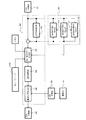
図1は、本発明の第1実施形態における振れ検出装置及びブレ補正光学機器の概要を説明するためのブロック図である。本実施形態では、銀塩フィルムを使用するブレ補正カメラを例に挙げて説明する。
【0023】
(ブレ補正カメラの概要)
半押しスイッチSW1は、図示しないレリーズボタンの半押し動作に連動してONとなるスイッチである。この半押しスイッチSW1がONとなることにより、図示しない測光部による測光演算、図示しないオートフォーカス駆動部によるオートフォーカス駆動など一連の撮影準備動作を開始する。また、半押しタイマー100がOFFであった場合には、この半押しスイッチSW1のONに同期して半押しタイマー100がONとなる。
【0024】
全押しスイッチSW2は、不図示のレリーズボタンを更に押し込む全押し動作に連動してONとなるスイッチである。このスイッチがONとなることにより、ミラー130のアップ動作、図示しないシャッタ機構によるシャッタの開閉、ミラー130のダウン動作、給送モータ150によるフィルム140の巻き上げなどの一連の撮影動作が行われる。
【0025】
半押しタイマー100は、半押しスイッチSW1がONとなったと同時にONとなり、半押しスイッチSW1がONの間は、ONのままであり、また、半押しスイッチSW1がOFFとなってからも、一定時間は、ONのままとなっているタイマーである。この半押しタイマー100は、ONと同時にカウントを開始し、ONの間は、カウントを継続する。
【0026】
電源供給部110は、カメラの各部に電源を供給する部分であり、カメラの半押タイマー100がONの間、角速度センサ10を始め、カメラシステム内で電源が必要とされるところに電源を供給し続ける。また、半押しタイマー100がOFFのとき、電源供給部110は、角速度センサ10等への電源の供給を停止する。従って、カメラの半押しタイマー100がONの間に限り、角速度センサ10によるカメラの振動検出が可能となる。
【0027】
角速度センサ10は、カメラに加えられた振動を角速度値で検出するセンサであり、角速度センサ10にかかるコリオリ力を利用して角速度を検出し、検出結果を電圧信号として出力する振動検出部である。角速度センサ10aは、図中X軸方向の角度ブレを検出するセンサであり、角速度センサ10bは、図中Y軸方向の角度ブレを検出するセンサである。このように、角速度センサ10a,10bを互いに異なる軸方向に配置することにより、カメラの振動を2次元で検出することが可能となる。
角速度センサ10により出力された電圧信号は、増幅部20に送信される。なお、角速度センサ10は、電源供給部110より電源が供給されている間のみ、角速度の検出が可能となる。
【0028】
増幅部20は、角速度センサ10の出力を増幅する増幅部である。一般的に角速度センサ10からの出力は、小さいため、そのままA/D変換器30によってデジタル化してマイコン90内で処理しようとしても、角速度値の分解能が低すぎ(1ビットあたりの角速度値が大きすぎ)て正確な振動検出をすることができず、ブレ補正の精度を上げることができない。そこで、A/D変換器30に入力する前に角速度信号を増幅しておく。そうすると、マイコン90内での角速度値の分解能を上げる(1ビットあたりの角速度値を小さくする)ことができ、ブレ補正の精度を上げることができる。
増幅部20は、角速度センサ10a,10bにそれぞれ対応して増幅部20a,20bの2つが設けられている。また、増幅部20には、信号の増幅をするだけではなく、センサ出力に含まれる高周波ノイズを低減させることを目的とした、ローパスフィルタを付加してもよい。
増幅部20により増幅した角速度信号(以下、振れ検出信号)は、A/D変換器30へ送信される。
【0029】
A/D変換器30は、アナログ信号をデジタル信号に変換する変換器である。本実施形態では、A/D変換器30a,30bと、A/D変換器30c,30dとが設けられている。
A/D変換器30a,30bは、増幅部20から送られてきたアナログの振れ検出信号を、デジタル信号に変換する変換器である。振れ検出信号をデジタル信号に変換することで、マイコン90内での演算処理が可能となる。ここで変換された振れ検出信号は、駆動信号演算部50a,50bと異常振れ検出部40a,40bに入力される。
A/D変換器30c,30dは、駆動部70から送られてきたブレ補正レンズ位置情報(アナログ信号)をデジタル信号に変換する変換器である。変換されたブレ補正レンズ位置情報は、駆動信号演算部50a,50bに送信される。
【0030】
なお、本実施形態では、A/D変換器30は、マイコン90に内蔵されているものを使用することを前提にしているが、この例に限らず、マイコン90とは、別体のA/D変換器を用いても良い。
また、本実施形態では、増幅部20a,20bに対応するようにA/D変換器30a,30bの2つのA/D変換器を設けているが、A/D変換器を1つにして変換動作を時間的に振り分けるようにしてもよい。例えば、増幅部20aの信号を変換した後、増幅部20bの信号を変換し、その後増幅部20a,増幅部20b,増幅部20a...と変換を繰り返すようにしてもよい。これは、A/D変換器30c,30dについても同様である。
【0031】
異常振れ検出部40は、A/D変換器30から送られてきた振れ検出信号や、駆動信号演算部50で演算された基準値等から、カメラの振れの状態を検出する部分である。振れの状態は、通常の使用(構図の変更などは一切行われず、かつ、乗り物などで使用していない)での振動(以下、通常振れ)と、流し撮りが行われたり乗り物で使用されたりしたときの振動(以下、異常振れ状態)とに分け、異常振れ検出部40は、そのうちのどちらの状態にあるかを検出する。さらに、異常振れ検出部40は、異常振れ状態が検出されたときは、異常振れの種別を種別1(第1の異常振れ状態)、種別2(第2の異常振れ状態)に分ける。これらを簡単にまとめると以下のようになる。
【0032】
(1)通常振れ状態
撮影者の意図しない振れによってのみ振動している場合に、通常振れ状態と判断する。この場合、撮影者は、足場の安定したところにいると推定される。
(2)異常振れ状態
(2−1)種別1
比較的緩い流し撮りの状態、すなわち、撮影者の意図しない振れと意図する振れが混在する振動の場合に、異常振れ状態の種別1であると判断する。また、乗り物での使用状態、すなわち、撮影者の意図しない振れによってのみ振動しているが、足場が安定していないため通常の使用よりも振幅が大きい振動の場合にも、種別1と判断する。
(2−2)種別2
速い流し撮りなど、撮影者の意図する振れが支配的な状況には、異常振れ状態の種別2であると判断する。
異常振れ検出部40によるこれらの検出結果は、駆動信号演算部50に送信され、駆動信号演算部50は、その結果に応じて演算方法を変更する。
【0033】
駆動信号演算部50は、A/D変換器30から送信されてきた振れ検出信号とブレ補正レンズ位置情報から、ブレ補正レンズ80を駆動するための駆動信号を演算し、駆動信号を出力する演算部である。まず、未加工の振れ検出信号から基準値を演算し、その基準値を未加工の振れ検出信号値から減算して振れ検出信号を算出する。振れ検出信号が算出されたら、駆動信号演算部50は、モードスイッチ160、全押しスイッチSW2の状態、異常振れ検出部40の検出結果に応じて振れ検出信号を変更する。
なお、駆動信号演算部50が振れ検出信号に対して行う変更に関する処理動作は、後に説明する。
【0034】
上記変更後の振れ検出信号を積分することにより、角速度信号を角変位信号へと変換し、これにレンズの焦点距離などの諸条件を加味してブレ補正レンズ80の目標駆動位置を演算する。最後に、この目標駆動位置情報と駆動部70から送られてくるブレ補正レンズ80の位置情報から駆動信号を演算する。
【0035】
なお、本実施形態では、駆動信号演算部50a,50bの2つの駆動信号演算部が設けられている。しかし、これを1つにして駆動信号演算動作を時間的に振り分けるようにしてもよい。例えば、X軸方向の信号の駆動信号を演算した後、Y軸方向の信号を駆動信号を演算し、その後X,Y,X,Y...と交互に駆動信号を演算するようにしてもよい。
駆動信号演算部50の内部構成の詳細については、図2において別途説明をする。
【0036】
D/A変換器60は、駆動信号算部50で演算された駆動信号(デジタル信号)をアナログ信号に変換するためのD/A変換器である。変換されたアナログ信号は、駆動部70に送信される。
なお、本実施形態では、D/A変換器60は、マイコン90に内蔵されているものを使用することを前提にしているが、これに限らず、マイコン90とは、別体のD/A変換器を用いてもよい。
また、本実施形態では、D/A変換器60a,60bの2つD/A変換器が設けられているが、D/A変換器を1つにして、変換動作を時間的に振り分けるようにしてもよい。例えば、X軸方向の信号を変換した後、Y軸方向の信号を変換し、その後X,Y,X,Y...と変換するようにしてもよい。
【0037】
駆動部70は、D/A変換器60から送信されてきた駆動信号(アナログ信号)を基に、ブレ補正レンズ80を駆動する駆動部である。駆動部70は、ブレ補正レンズ80を駆動するためのアクチュエータや、ブレ補正レンズ80の位置を検出する位置検出センサ等を有している。位置検出センサの出力は、A/D変換器30を経由して駆動信号演算部50に送信される。
ブレ補正レンズ80を2次元方向で駆動する必要があるため、この駆動部70は、駆動部70a,70bの2つ設ける必要がある。
【0038】
ブレ補正レンズ80は、撮影装置のレンズ鏡筒170に内蔵された図示しない結像光学系の一部であり、光軸Iと略直交する平面内を動くことができる単レンズ又は複数枚のレンズより構成されるブレ補正光学系である。ブレ補正レンズ80は、駆動部70によって光軸Iと略直交する方向に駆動され、結像光学系の光軸Iを偏向させる。
【0039】
写真等の像のブレは、手振れ等のカメラに加えられる振動により、露光中に結像面(フィルム140の面)の像が動いてしまうことにより発生する。しかし、図1に示すようなブレ補正カメラにおいては、角速度センサ10などの振動検出センサが内蔵されており、その振動検出センサにより、カメラに加えられた振動を検出することができる。そして、カメラに加えられた振動が検出されれば、その振動による結像面の像の動きを知ることができるので、結像面上の像の動きが止まるようにブレ補正レンズ80を動かすことによって、結像面上の像の動き、すなわちブレを補正することができる。
【0040】
マイコン90は、A/D変換器30、異常振れ検出部40、駆動信号演算部50、D/A変換器60等が組み込まれているマイコンである。ここで説明した動作のほかに、図示しないオートフォーカス駆動などの制御も、このマイコン90が行うようにしてもよい。
【0041】
ミラー駆動モータ120は、電源供給部110から電源の供給を受け、必要に応じてミラー130のアップ、ダウン動作を行うモータである。なお、本実施形態では、ミラー駆動モータ120は、電磁的アクチュエータであるモータを使用する例を示したが、これに限らず、例えば、バネのような機械的な手段を利用してもよい。
【0042】
ミラー130は、図示しない結像光学系の光を偏向して、図示しないペンタプリズム及びファインダに送るミラーである。露光動作時は、このミラーがアップし、結像光学系からの光は、フィルム140の面に到達する。
【0043】
フィルム140は、結像光学系が結像する映像を記録するフィルムである。なお、本実施形態では、銀塩カメラであることを前提としているが、これに限らずCCDやC−MOSセンサのようなエリアセンサを用いてもよい。
【0044】
給送モータ150は、露光終了後に、フィルム140の駒送りをするモータである。なお、撮像媒体にフィルム140ではなく、CCDなどのエリアセンサが用いられる場合には、このモータ自体は不必要となる。
【0045】
モードスイッチ160は、撮影者が使用用途(撮影状態)に合わせてブレ補正動作のモードを切り替えるスイッチである。本実施形態では、モード1(第1のモード),モード2(第2のモード)を選択できるようになっている。モードスイッチ160により選択設定するモード1,2の想定する用途を以下に示す。
モード1:略静止した撮影、構図の変更、流し撮りなどを含む通常の使用時を想定し、乗り物などに乗らず、足場が安定した状態であることにより、撮影者の動作以外に起因する振れが生じない状態での撮影。
モード2:乗り物に乗った状態での撮影。足場が安定しない状態。
モードスイッチ160で設定された内容は、駆動信号演算部50に送信される。
【0046】
カメラボディ180は、撮影部を有し、レンズ鏡筒170を交換可能な一眼レフカメラのカメラ本体である。なお、本実施形態では、一眼レフカメラである例を示したが、これに限らず、例えば、コンパクトカメラのような、レンズ非交換式でもよい。
【0047】
図2は、駆動信号演算部50及び異常振れ検出部40の内部構成を示す図である。
なお、これ以降に説明する内容は、X方向Y方向ともに共通の内容であるため、特に方向に関しては明記せず、まとめて説明を行う。
駆動信号演算部50は、基準値演算部52,振れ検出信号処理部53,積分演算部54,駆動信号算出部58を有している。
【0048】
基準値演算部52は、A/D変換器30(30a,30b)より送信されてきた未加工の振れ検出信号から、駆動信号演算のための基準値を演算する演算部である。
通常、静止状態での基準値は、角速度センサ10が完全に静止している状態での出力(以下、ゼロ出力)値とすればよい。しかし、このゼロ出力値は、ドリフトや温度などの環境条件で変動してしまうため、基準値を固定値とすると、ブレ補正の精度が低下したり、不自然な挙動をしてしまうことがある。
従って、実際に使用されている状態、つまり撮影者の手振れの信号から基準値を演算し、ゼロ出力を求めることが望ましく、本実施形態でも、基準値を振れ検出信号から演算する基準値演算部52を設けている。
基準値演算部52は、通常振れ状態と異常振れ状態とで、基準値の演算式を変更する。その一例を以下に示す。
【0049】
【数1】

ここで、ωは、振れ検出信号であり、ω0 は、振れの基準値である。また、これらの変数に付いているサフィックスtは、経過時間を表す変数であり、本実施形態では、サンプリングの回数によって表すこととしており、整数値である。これらの式は、いずれも振れ検出信号の移動平均を表すものであるが、通常振れ状態と異常振れ状態とで平均に使用するデータの数が異なっている。
【0051】
通常振れ状態の基準値は、角速度センサのゼロ出力値に近い値であることが望ましい。角速度センサ10のゼロ出力信号の周波数は、人間の手振れの周波数に比べるとはるかに低い。よって、基準値は、振れ検出信号の低周波成分を抽出すればよい。そこで、振れ検出信号、すなわち手振れの移動平均を演算して手振れ検出信号の基準値を演算している。そして、なるべく低い周波数成分のみを抽出するため、移動平均に使用するデータの数K0を多くしている。
【0052】
異常振れ状態では、通常振れ状態よりも振れ検出信号が大きく変動する。例えば、構図の変更などでは、撮影者が意図してカメラを振るため、通常振れ状態よりも振れ量が大きくなる。
異常振れ状態における構図変更などは、撮影者の意図する振れが含まれるため、それまでも補正してしまうのは好ましくない。そこで、異常振れ状態では、ブレ補正を抑制させるために振れ検出信号に対する基準値の応答を速くする。ここでは、異常振れ状態の基準値演算における移動平均に使用するデータの数K1を通常振れ状態のK0よりも少なくしている。こうすることで、基準値の応答を速くすることができ、通常振れ状態の時と比較してブレ補正動作を抑制することができるため、その結果として撮影が意図したとおりに構図を決めることが可能となる。
【0053】
基準値演算部52で演算された基準値は、振れ検出信号から減算され、また、異常振れ検出部40へ送信される。
なお、基準値の演算は上記のような移動平均に限らず、FIRフィルタやIIRフィルタ等のローパスフィルタを用いてもよい。この場合には、通常振れ状態の遮断周波数は、異常振れ状態の遮断周波数よりも低く設定するとよい。
【0054】
振れ検出信号処理部53は、角速度センサ10の出力である未加工の振れ検出信号から基準値を減算した振れ検出信号を処理(変更)する部分である。
以下に、駆動信号演算部50の振れ検出信号処理部53が振れ検出信号に対して行う変更に関する処理について説明する。
(1)異常振れ検出部40が通常振れ状態であると判断した場合には、振れ検出信号処理部53は、モードスイッチ160やスイッチSW2の状態によらず、演算した振れ検出信号の変更を行わない。
【0055】
(2)異常振れ検出部40が異常振れ状態であると判断した場合
(2−1)異常振れ検出部40が異常振れ状態であると判断し、かつ、モードスイッチ160がモード1である場合であって、全押しスイッチSW2がOFFとなっているときには、振れ検出信号処理部53は、振れ検出信号を0とする。振れ検出信号が0となると、カメラが完全に静止している場合のブレ補正動作を行うこととなるので、ブレ補正レンズ80が停止する。これは、半押し中の構図変更や流し撮りの際にファインダ像に不自然な動きが現れないようにするためである。
【0056】
また、異常振れ検出部40が異常振れ状態であると判断し、さらに、モードスイッチ160がモード1であり、全押しスイッチSW2がONとなっている場合であって、異常振れの種別が種別1の場合は、振れ検出信号の変更はしない。そうすると、ブレ補正レンズ80が駆動されてブレ補正が実行される。これは、信号に含まれる撮影者の意図しない成分のみ補正するためである。
【0057】
さらに、異常振れ検出部40が異常振れ状態であると判断し、さらに、モードスイッチ160がモード1であり、全押しスイッチSW2がONとなっている場合であって、異常振れの種別が種別2の場合は、振れ検出信号を0とする。これは、撮影者の意図する振れを補正してしまって撮影結果が悪化してしまうことを防ぐためである。
【0058】
(2−2)異常振れ検出部40が異常振れ状態であると判断し、かつ、モードスイッチ160がモード2である場合には、演算した振れ検出信号の変更は行わない。これは、全押しスイッチSW2の状態にはよらない。前述したようにモード2は、乗り物に乗った状態での撮影を想定しており、振れ検出信号には、撮影者の意図する振れは、殆ど含まれないことを想定していることから、ブレ補正を実行するようにしている。
【0059】
積分演算部54は、振れ検出信号(角速度)を積分して振れ角度情報に変換し、さらにブレ補正レンズの目標駆動位置を演算する演算部である。積分演算部54が行う演算の一例を以下に示す。
【0060】
【数2】
式(3)中の各記号は、θ(t):目標駆動位置,ω(t):振れ検出信号,ω0 (t):基準値,t:時間(整数値)であり、Cは、レンズの焦点距離等の条件によって決まる定数である。
【0062】
駆動信号算出部58は、積分演算部54で演算した目標駆動位置と、駆動部70からA/D変換器30(30c,30d)を経由して送信されてきたブレ補正レンズ80の位置とによって、ブレ補正レンズ80を駆動するための信号を算出する部分である。
駆動信号算出部58で行う演算は、目標駆動位置とブレ補正レンズの位置との偏差を求め、偏差に比例する項、偏差の積分に比例する項、偏差の微分に比例する項を加算して駆動信号を演算するPID制御が一般的である。なお、駆動信号の演算方法は、PID制御に限らず、他の方法でも良い。
【0063】
異常振れ検出部40は、異常振れ開始検出部41,異常振れ種別判定部42,異常振れ終了検出部43を有している。
異常振れ開始検出部41は、異常振れの開始を検出する部分である。異常振れ開始検出部41は、A/D変換器30から送られてきた角速度センサ10の出力である未加工の振れ検出信号と、基準値演算部52から送られてきた基準値とを利用して異常振れの開始を検出する。異常振れ開始検出部41は、振れの状態が通常振れの時にのみ動作し、異常振れの時は動作しない。
また、異常振れ開始検出部41は、異常振れの開始を検出したら基準値演算部52にその情報を送信し、基準値演算部52は、基準値の演算方法を変更する。本実施形態では、式(1)により演算していた基準値を式(2)により演算するように切り替える。さらに、異常振れ開始検出部41は、異常振れ種別判定部42、振れ検出信号処理部53にも異常振れ開始情報を送る。
【0064】
異常振れ種別判定部42は、異常振れの種別を種別1(第1の異常振れ状態)、種別2(第2の異常振れ状態)に分ける部分である。具体的には、未加工の振れ検出信号に高い周波数成分が含まれていれば種別1とし、低い周波数成分のみであれば種別2とする。異常振れ種別判定部42は、異常振れの開始が検出されてから、異常振れの終了が検出されるまでの間は動作し、通常振れの場合は動作しないようになっている。
異常振れ種別判定部42による異常振れ種別の判定結果は、振れ検出信号処理部53へ送信される。
【0065】
異常振れ終了検出部43は、A/D変換器30から送られてきた角速度センサ10の出力である未加工の振れ検出信号と、基準値演算部52より送られてきた基準値を利用して異常振れの終了を検出する部分である。異常振れ終了検出部43は、異常振れ状態に動作し、通常振れ状態では動作しない。
また、異常振れ終了検出部43は、異常振れの終了を検出したら基準値演算部52にその情報を送信し、基準値演算部52は、基準値の演算方法を変更する。本実施形態では、式(2)により演算していた基準値を式(1)により演算するように切り替える。さらに、異常振れ終了検出部43は、異常振れ種別判定部42、振れ検出信号処理部53にも異常振れ終了情報を送る。
【0066】
(ブレ補正カメラの動作)
次に、本実施形態におけるブレ補正カメラの動作を説明する。
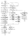
図3は、本実施形態における振れ検出装置を内蔵したカメラシステム全体の流れを示すフローチャートである。
【0067】
ステップ(以下、Sとする)10では、半押しスイッチSW1がONとなっているか否かを判定する。ONならばS20へ進み、OFFならばS190に進む。
【0068】
S20では、カウンタTsw1をリセットし、カウント値を0とする(Tsw1=0とする)。カウンタTsw1は、半押しスイッチSW1がOFFになってからの経過時間を計測するカウンタであり、カウント値は、整数である。このカウンタTsw1は、半押しスイッチがONの間は、0のままで、半押しスイッチSW1がOFFで、かつ半押しタイマー100がONの間のみ動作する。
S30では、半押しタイマー100がOFFであるか否かを判定する。OFFであればS40へ進み、ONであればS220へ進む。
【0069】
S40では、カウンタtをリセットし、カウント値を0とする(t=0とする)。カウンタtは、半押しタイマー100がONとなっている時間を計測するカウンタである。このカウンタtは、整数値カウンタであり、半押しタイマー100がONとなったと同時にカウント動作を開始し、半押しタイマー100がONの間は、カウント動作を続ける。
【0070】
S50では、異常振れ検出部40の検出結果を通常振れ状態にセットする。
S60では、半押しタイマー100をONにする。
S70では、角速度センサ10をONとし、振動の検出を開始する。この他、A/D変換器30による変換動作もここで開始される。
【0071】
S80では、S50で通常振れにセットされたので、通常振れ用の基準値の演算を開始する。本実施形態では、式(1)により基準値を演算する。
S90では、S50で通常振れにセットされたので、異常振れ開始検出部41は、異常振れの開始を検出するための演算を開始する。
S100では、駆動信号演算部50が駆動信号の演算を開始する。
S110では、駆動信号演算部50から得た駆動信号に基づき、駆動部70がブレ補正レンズ80の駆動を開始する。
S120では、全押しスイッチSW2がONであるか否かを判定する。全押しスイッチSW2がOFFの場合は、S160に進む。全押しスイッチSW2がONの場合は、S130に進む。
【0072】
S130では、角速度センサ10の出力、基準値、振れの状態判定結果、モードスイッチ160の状態からそれぞれの状況に適した駆動信号の演算を行う(駆動信号演算2)。
S140では、S130で演算した駆動信号に基づいてブレ補正レンズ80を駆動する。
S150では、ミラー130のアップ、不図示のシャッタの開閉、ミラー130のダウン、給送モータ150の駆動などの撮影動作を行う。
【0073】
S160では、角速度センサ10の出力、基準値、振れの状態判定結果、モードスイッチ160の状態からそれぞれの状況に適した駆動信号の演算を行う(駆動信号演算1)。
なお、このS160及び上述のS130における駆動信号演算1及び駆動信号演算2は、先に説明した駆動信号演算部50の振れ検出信号処理部53が振れ検出信号に対して行う変更により演算の結果が変化する演算であり、別途図4及び図5に示すフローチャートにおいて説明する。
S170では、S160で演算した駆動信号に基づいてブレ補正レンズ80を駆動する。
S180では、半押しタイマー100のカウンタtを1つ進める(t=t+1の演算を行う)。
【0074】
S190では、半押しタイマー100がONであるか否かを判定する。半押しタイマー100がONならばS200へ進み、半押しタイマー100がOFFならばS10へ戻り、半押しスイッチSW1の検出を続行する。
S200では、このステップに進んだ時点では、カメラは半押しスイッチSW1がOFFで半押しタイマー100がONの状態になっているので、この状態が継続している時間を計測するため、カウンタTsw1を1つ進める(Tsw1=Tsw1+1の演算を行う)。
【0075】
S210では、カウンタTsw1の値がしきい値T_SW1よりも小さいか否かを判定する。ここで、しきい値T_SW1は、カウンタTsw1の上限を決めるための定数で、半押しスイッチSW1がOFFとなってから半押しタイマー100がOFFとなるまでの時間を決めるものである。
カウンタTsw1がしきい値に満たない場合、すなわち肯定判定の場合は、半押しタイマー100は、OFFとせず、S220に進む。一方、カウンタTsw1がこのしきい値と等しくなった場合、すなわちこのステップで否定判定となった場合は、S290に進み、半押しタイマー100をOFFにする処理(S320)、及び、半押しタイマー100のOFFに伴う処理(S300,S310)を行う。
【0076】
S220では、角速度センサ10は、ONの状態を継続し、振れの検出を継続して行う。また、A/D変換器30による変換動作も継続する。
S230では、異常振れ検出部40による検出結果をモニタする。検出結果が通常振れ状態であればS240に進み、異常振れ状態であればS260に進む。
S240では、基準値演算部52が通常振れ状態の基準値を演算する。本実施形態では、式(1)により基準値を演算する。
【0077】
S250では、異常振れ開始検出部41が異常振れの開始を検出する演算を行う。ここで異常振れの開始が検出されたら、検出結果を通常振れ状態から異常振れ状態に設定を変更する。
S260では、基準値演算部52が異常振れ状態の基準値を演算する。本実施形態では、式(2)により基準値を演算する。
S270では、異常振れ種別判定部42が、異常振れの種別を判定する演算を行う。
S280では、異常振れ終了検出部43が異常振れの終了を検出する演算を行う。ここで異常振れの終了が検出されたら、検出結果を異常振れ状態から通常振れ状態に設定を変更する。
【0078】
S290では、異常振れ開始検出部41又は異常振れ終了検出部43が行っている異常振れの開始又は終了を検出するための演算を停止する。
S300では、基準値演算部52が行う基準値の演算を停止する。
S310では、角速度センサ10への電源の供給を停止し、角速度センサをOFFとする。
S320では、半押しタイマー100をOFFにしてS10に戻り、半押しスイッチSW1の状態検出を行う。
【0079】
図4は、半押しON時における駆動信号演算1(図3におけるS160)の流れを示すフローチャートである。
S161では、異常振れ検出部40が検出した振れの状態検出結果をモニタする。通常振れ状態の場合はS164へ進み、異常振れ状態の場合はS162へ進む。
S162では、モードスイッチ160の設定をモニタする。モード1の場合はS163へ進み、モード2の場合はS164へ進む。
S163では、振れ検出信号処理部53は、振れ検出信号を0とする。これにより、その後の積分結果は、ホールド(一定値に固定)されることになり、ブレ補正レンズ80は、見かけ上停止する。
S164では、積分演算部54が振れ検出信号を積分し、角度情報に変換する。
S165では、駆動信号算出部58が角度情報にレンズの焦点距離情報、レンズ位置情報を加味してブレ補正レンズの駆動信号を算出する。
【0080】
図5は、全押しON時における駆動信号演算2(図3におけるS130)の流れを示すフローチャートである。
S131では、異常振れ検出部40が検出した振れの状態検出結果をモニタする。通常振れ状態の場合はS135へ進み、異常振れ状態の場合はS132へ進む。
S132では、モードスイッチ160の設定をモニタする。モード1の場合はS133へ進み、モード2の場合はS135へ進む。
S133では、異常振れ種別判定部42による異常振れ種別の判定結果をモニタする。種別1の場合は135へ進み、種別2の場合はS134へ進む。
S134では、振れ検出信号処理部53は、振れ検出信号を0とする。これにより、その後の積分結果は、ホールド(一定値に固定)されることになり、ブレ補正レンズ80は、見かけ上停止する。
S135では、積分演算部54が振れ検出信号を積分し、角度情報に変換する。
S136では、駆動信号算出部58が角度情報にレンズの焦点距離情報、レンズ位置情報を加味してブレ補正レンズの駆動信号を算出する。
【0081】
図6は、図4及び図5に示した動作により、場合分けされる駆動信号演算1,2をまとめた表である。
半押し中、かつ、モード1の場合は、撮影者の意図が少しでも入っていればブレ補正を停止する。したがって、通常の使用や流し撮り、構図変更に向いた設定となる。
半押し中、かつ、モード2の場合は、常にブレ補正を動作させた状態なので、大きく揺れる乗り物での使用に向いた設定となる。
このように、用途に応じてモードスイッチ160を切り替えることにより、あらゆる状況でファインダ像の見えが自然で不快感を与えないようにすることができる。
【0082】
また、露光中(全押し中)、かつ、モード1の場合であって、異常振れの種別が種別1のときは、撮影者の意図しない振れが含まれるので、それを補正することにより撮影結果が向上できる。
同様に、露光中(全押し中)、かつ、モード1の場合であって、異常振れの種別が種別2のときは、撮影者の意図する振れが支配的なので、ブレ補正を停止し、撮影結果に悪影響を及ぼすことを防止できる。
【0083】
さらに、露光中(全押し中)、かつ、モード2の場合は、基本的に撮影者の意図しない振れのみ含まれることを前提としているので、常にブレ補正を実行し、撮影結果を向上させることができる。
【0084】
本実施形態によれば、異常振れ検出部40によって振動状態を分類し、振れの種別の判定も行い、モードスイッチ160との組み合わせにより、どのような状況にあっても、最適な条件で撮影することができる。
また、一般的な撮影者は、乗り物からの撮影をすることは希なので、常にモード1に設定しておけば、あらゆる状況に対処することができると同時に、モードスイッチ160をこまめに切り替えなければならないという煩わしさから解放され、快適にブレ補正システムを使用することができる。
【0085】
(変形形態)
以上説明した実施形態に限定されることなく、種々の変形や変更が可能であって、それらも本発明の均等の範囲内である。
例えば、各実施形態において、銀塩フィルムを使用するブレ補正カメラに本発明を適用した例を示したが、これに限らず、例えば、CCD等を用いて電気的に映像を記録するいわゆるデジタルカメラでもよいし、ビデオカメラその他の光学機器でもよい。
【0086】
【発明の効果】
以上詳しく説明したように、請求項1の発明によれば、振動検出部を含む装置の振動状態について、流し撮りを行っている第1の異常ブレ状態と、前記流し撮りよりも速い流し撮りを行っている第2の異常ブレ状態と、前記流し撮り及び前記速い流し撮りを行っていない通常ブレ状態とに判別する振動状態判別部と、振動状態判別部の判別結果に応じて駆動信号算出部の算出方法を制御する駆動信号算出制御部とを備えるので、振動の状態に合わせて最適な制御を行うことができる。
【0087】
また、振動状態判別部は、流し撮りを行っている第1の異常ブレ状態と、前記流し撮りよりも速い流し撮りを行っている第2の異常ブレ状態と、前記流し撮り及び前記速い流し撮りを行っていない通常ブレ状態とに判別するので、振動の状態に合わせて最適な制御を行うことができ、撮影者の意図に合った制御を行うことができる。
【0089】
請求項2の発明によれば、駆動信号算出制御部は、モードスイッチの設定状態に応じて駆動信号の算出方法を変更する制御を行うので、撮影者の意図する制御を確実に行うことができる。
【0090】
また、駆動信号算出制御部を用いて、撮影露光中であるか否かにより、駆動信号の算出方法を変更する制御を行うことにより、撮影者がファインダ等で観察する像により不快感を覚えることなく、ブレ補正動作を行うことができる。
【0091】
請求項2の発明によれば、駆動信号算出制御部は、振動状態判別部が通常ブレ状態と判別した場合には、モードスイッチの設定状態及び撮影露光中であるか否かによらず、ブレ補正光学系を駆動してブレ補正動作を行うように駆動信号の算出を実行させる制御を行うので、ブレ補正が必要な通常振れ状態において、確実にブレ補正動作を行うことができる。
【0092】
請求項3の発明によれば、モードスイッチは、振動状態判別部の判別結果に応じて自動的に駆動信号算出制御部の制御を変更する第1のモードと、振動状態判別部の判別結果及び撮影露光中であるか否かによらずブレ補正光学系を駆動してブレ補正動作を行うように駆動信号算出制御部を制御する第2のモードとを選択可能であるので、通常は特別な操作をすることなく最適な動作を行い、必要なときに撮影者の意図により確実にブレ補正動作を行うことができる。
【0093】
請求項4の発明によれば、駆動信号算出制御部は、振動状態判別部が第1の異常ブレ状態と判別し、かつ、モードスイッチが第1のモードとなっているときであって、撮影露光準備中はブレ補正動作を行わず、撮影露光中はブレ補正動作を行うように制御を行うので、撮影者がファインダ等で観察する像により不快感を覚えることなく、ブレ補正動作を行うことができる。
【0094】
請求項5の発明によれば、駆動信号算出制御部は、振動状態判別部が第2の異常ブレ状態と判別し、かつ、モードスイッチが第1のモードとなっている場合には、撮影露光中であるか否かによらず、ブレ補正光学系の駆動を停止してブレ補正動作を行わないように駆動信号の算出を実行させる制御を行うので、撮影者が意図する流し撮り等を補正することなく、被写体の追従を容易に行うことができる。
【図面の簡単な説明】
【図1】本発明の第1実施形態における振れ検出装置及びブレ補正光学機器の概要を説明するためのブロック図である。
【図2】駆動信号演算部50及び異常振れ検出部40の内部構成を示す図である。
【図3】本実施形態における振れ検出装置を内蔵したカメラシステム全体の流れを示すフローチャートである。
【図4】半押しON時における駆動信号演算1の流れを示すフローチャートである。
【図5】全押しON時における駆動信号演算2の流れを示すフローチャートである。
【図6】図4及び図5に示した動作により、場合分けされる駆動信号演算1,2をまとめた表である。
【図7】振れ検出装置を含んだ従来のブレ補正装置の基本的な構成を示すブロック図である。
【符号の説明】
10a,10b 角速度センサ
40 異常振れ検出部
41 異常振れ開始検出部
42 異常振れ種別判定部
43 異常振れ終了検出部
50 駆動信号演算部
52 基準値演算部
53 振れ検出信号処理部
54 積分演算部
58 駆動信号算出部
70a,70b 駆動部
80 ブレ補正レンズ
160 モードスイッチ
170 レンズ鏡筒
180 カメラボディ[0001]
BACKGROUND OF THE INVENTION
The present invention relates to a shake correction device such as an optical device such as binoculars or a photographing device such as a camera incorporating a shake detection device that detects vibration caused by hand shake or the like.
[0002]
[Prior art]
The main vibration source of vibration applied to an optical device such as binoculars or a photographing device such as a camera is user shake. 2. Description of the Related Art Conventionally, a shake correction device has been proposed as a means for correcting image vibration and image blur due to camera shake.
[0003]
The operation of the conventional shake correction apparatus will be described below with reference to FIG.
FIG. 7 is a block diagram showing a basic configuration of a conventional blur correction apparatus including a shake detection apparatus.
The
[0004]
The target drive
[0005]
The
The actuator portion of the
[0006]
The position detection sensor portion of the
[0007]
The light emitted from the IRED 74 first passes through the slit 76 a so that the width of the light beam is reduced and reaches the
[0008]
[Problems to be solved by the invention]
Such a blur correction device is effective in correcting image blur due to camera shake that is not intended by the user, and is effective, for example, in a case where an image is normally held still. However, the usage status of the camera is not limited to the case of taking a still image. For example, some photographers often take a panning shot, or often take a picture of a helicopter or other vehicle. Also, when shooting with an AF camera, there are many cases where the composition is changed with AF lock after focusing on the main subject with AF. As described above, camera usage is wide, and a blur correction system that can be used effectively in these situations is desired.
[0009]
In various situations as described above, what is required of the shake correction apparatus is as follows.
(Request 1) In any situation, the image quality of the photographed result (photo) is better than when no blur correction is performed.
(Request 2) Observing the viewfinder image and not feeling uncomfortable. In other words, when you are standing still or shooting from a vehicle, you can confirm that blur correction is working (the image appears to stop), and in panning, it is easy to follow the subject.
In order to cope with such a demand, for example, Japanese Patent Application Laid-Open No. 05-142614, Japanese Patent Application Laid-Open No. 07-261234, Japanese Patent Application Laid-Open No. 10-213832, Japanese Patent Application Laid-Open No. 2000-039640, etc. There have been proposed methods for distinguishing from unintended shakes and for classifying shakes (normally held, taking a panning shot, riding on a vehicle, etc.).
However, these conventional blur correction apparatuses do not always operate as intended by the photographer. For example, there is a case where a relatively large vibration is applied when riding on a vehicle, and this is erroneously determined to be a panning shot.
[0010]
On the other hand, in order to cope with various conditions and operate as intended by the photographer, there is a shake correction device in which the photographer changes a shake correction mode by switching a switch. In this shake correction apparatus, the switch is switched between the case where no panning is performed and the case where no panning is performed, automatic detection of panning is not performed. However, such switch setting has the following problems.
[0011]
Even when shooting normally, the player often performs a panning operation (composition change) to determine the composition. However, in normal shooting, there is no switch setting for automatic detection of panning shots, so if you change the composition, the movement of the image becomes unnatural, or it takes time until the image stabilizes after the composition is determined. There was a problem to do.
Further, in the worst case, there is a possibility that the photographing result is adversely affected (the image is blurred).
Further, in order to solve such a problem, it is complicated and not practical to switch the switch between when the composition is changed and after the composition is determined.
[0012]
SUMMARY OF THE INVENTION An object of the present invention is to provide a shake correction apparatus that can perform an operation intended by a photographer with a simple operation in any situation and can obtain an excellent shooting result.
[0013]
[Means for Solving the Problems]
The present invention solves the above problems by the following means. In addition, in order to make an understanding easy, although the code | symbol corresponding to embodiment of this invention is attached | subjected and demonstrated, it is not limited to this. That is, the invention of
[0016]
According to a second aspect of the present invention, there is provided the shake correction apparatus according to the first aspect, further comprising a mode switch (160) for switching a control state of the drive signal calculation control unit (53), wherein the drive signal calculation control unit includes the vibration When the state discriminating unit (40) discriminates the normal blur state, the blur correction optical system (80) is driven to perform the blur regardless of the setting state of the mode switch and whether or not the photographing exposure is being performed. A blur correction apparatus that performs control to execute calculation of the drive signal so as to perform a correction operation.
[0019]
Claim 3The invention ofClaim 2In the shake correction apparatus, the mode switch (160) includes a first mode in which the control of the drive signal calculation control unit (53) is automatically changed according to the determination result of the vibration state determination unit (40). The drive signal calculation control unit is controlled to drive the blur correction optical system (80) to perform the blur correction operation regardless of the determination result of the vibration state determination unit and whether or not the photographing exposure is being performed. The blur correction apparatus is characterized in that the second mode can be selected.
[0020]
Claim 4The invention ofClaim 3In the shake correction apparatus, the drive signal calculation control unit (53) is configured such that the vibration state determination unit (40) has a first abnormality.BlurWhen the mode switch is in the first mode and the mode switch is in the first mode, control is performed so that the blur correction operation is not performed during the preparation for shooting exposure and the blur correction operation is performed during the shooting exposure. This is a shake correction apparatus characterized by the above.
[0021]
Claim 5The invention ofClaim 3 or claim 4In the shake correction apparatus, the drive signal calculation control unit (53) is configured such that the vibration state determination unit (40) has a second abnormality.BlurWhen the state is determined and the mode switch (160) is in the first mode, the driving of the blur correction optical system (80) is stopped regardless of whether or not the photographing exposure is being performed. Then, the shake correction apparatus is characterized in that control is performed to calculate the drive signal so as not to perform the shake correction operation.
[0022]
DETAILED DESCRIPTION OF THE INVENTION
Hereinafter, embodiments of the present invention will be described in more detail with reference to the drawings.
FIG. 1 is a block diagram for explaining an outline of a shake detection device and a shake correction optical apparatus according to the first embodiment of the present invention. In the present embodiment, a description will be given by taking a blur correction camera using a silver salt film as an example.
[0023]
(Outline of image stabilization camera)
The half-press switch SW1 is a switch that is turned on in conjunction with a half-press operation of a release button (not shown). When the half-press switch SW1 is turned on, a series of photographing preparation operations such as photometry calculation by a photometry unit (not shown) and autofocus drive by an autofocus drive unit (not shown) are started. If the half-
[0024]
The full push switch SW2 is a switch that is turned on in conjunction with a full push operation of further pushing a release button (not shown). When this switch is turned on, a series of photographing operations such as the
[0025]
The half-
[0026]
The
[0027]
The
The voltage signal output from the
[0028]
The amplification unit 20 is an amplification unit that amplifies the output of the
The amplifying unit 20 includes two amplifying
An angular velocity signal (hereinafter, shake detection signal) amplified by the amplification unit 20 is transmitted to the A /
[0029]
The A /
The A /
The A /
[0030]
In this embodiment, it is assumed that the A /
In the present embodiment, two A / D converters A /
[0031]
The abnormal
[0032]
(1) Normal swing state
When the camera shakes only due to a shake that is not intended by the photographer, it is determined as a normal shake state. In this case, the photographer is estimated to be in a stable place on the scaffold.
(2) Abnormal shake state
(2-1)
In the case of a relatively loose panning state, that is, a vibration in which a shake that is not intended by the photographer and an intended shake are mixed, it is determined that the type is an abnormal
(2-2) Type 2
For situations where the shake intended by the photographer is dominant, such as fast panning, it is determined that the type 2 is abnormal shake state.
These detection results by the abnormal
[0033]
The drive
The processing operation related to the change performed by the drive
[0034]
The angular velocity signal is converted into an angular displacement signal by integrating the shake detection signal after the change, and the target driving position of the
[0035]
In the present embodiment, two drive signal calculation units, ie, drive signal calculation units 50a and 50b are provided. However, it is also possible to distribute the driving signal calculation operations in terms of time by using one unit. For example, after calculating the drive signal of the signal in the X-axis direction, the drive signal is calculated from the signal in the Y-axis direction. . . Alternatively, the drive signal may be calculated alternately.
Details of the internal configuration of the drive
[0036]
The D /
In the present embodiment, it is assumed that the D /
In the present embodiment, two D / A converters, D /
[0037]
The
Since it is necessary to drive the
[0038]
The
[0039]
Blur of an image such as a photograph occurs when an image on the imaging surface (the surface of the film 140) moves during exposure due to vibration applied to the camera such as camera shake. However, the shake correction camera as shown in FIG. 1 has a built-in vibration detection sensor such as the
[0040]
The
[0041]
The
[0042]
The
[0043]
The
[0044]
The
[0045]
The
Mode 1: Assuming normal use, including almost stationary shooting, composition change, panning, etc., because the platform is stable and the platform is in a stable state, shake caused by actions other than the photographer's movement Shooting in a state that does not occur.
Mode 2: Shooting while riding on a vehicle. The scaffold is not stable.
The content set by the
[0046]
Camera body180Has a shooting unit and lens barrel170It is a camera body of a single-lens reflex camera that can be replaced. In the present embodiment, an example of a single-lens reflex camera has been described. However, the present invention is not limited to this. For example, a non-lens interchangeable lens such as a compact camera may be used.
[0047]
FIG. 2 is a diagram illustrating an internal configuration of the drive
In addition, since the content demonstrated after this is the same content in X direction and Y direction, it does not specify in particular about a direction and it demonstrates collectively.
The drive
[0048]
The reference
Usually, the reference value in the stationary state may be an output value (hereinafter, zero output) value in a state where the
Therefore, it is desirable to calculate the reference value from the camera shake signal of the photographer in actual use, and obtain zero output. In this embodiment, the reference value calculation unit calculates the reference value from the shake detection signal. 52 is provided.
The reference
[0049]
[Expression 1]
Here, ω is a shake detection signal, and ω0Is a reference value for shake. Further, the suffix t attached to these variables is a variable representing the elapsed time, and is represented by the number of samplings in the present embodiment, and is an integer value. Each of these expressions represents a moving average of the shake detection signal, but the number of data used for averaging differs between the normal shake state and the abnormal shake state.
[0051]
The reference value for the normal shake state is desirably a value close to the zero output value of the angular velocity sensor. The frequency of the zero output signal of the
[0052]
In the abnormal shake state, the shake detection signal varies more greatly than in the normal shake state. For example, when changing the composition or the like, the photographer intentionally shakes the camera, so the shake amount is larger than that in the normal shake state.
The composition change in the abnormal shake state includes a shake intended by the photographer, and thus it is not preferable to correct it until then. Therefore, in the abnormal shake state, the response of the reference value to the shake detection signal is accelerated in order to suppress blur correction. Here, the number K1 of data used for moving average in the calculation of the reference value in the abnormal shake state is set to be smaller than K0 in the normal shake state. In this way, the response of the reference value can be speeded up, and the blur correction operation can be suppressed as compared with the normal shake state. As a result, the composition can be determined as intended for shooting. It becomes possible.
[0053]
The reference value calculated by the reference
The calculation of the reference value is not limited to the moving average as described above, and a low pass filter such as an FIR filter or an IIR filter may be used. In this case, the cutoff frequency in the normal shake state may be set lower than the cutoff frequency in the abnormal shake state.
[0054]
The shake detection
Hereinafter, a process related to a change performed by the shake detection
(1) When the abnormal
[0055]
(2) When the abnormal
(2-1) When the abnormal
[0056]
Further, when the abnormal
[0057]
Furthermore, when the abnormal
[0058]
(2-2) When the abnormal
[0059]
The
[0060]
[Expression 2]
Each symbol in the equation (3) is θ (t): target drive position, ω (t): shake detection signal, ω0(T): Reference value, t: Time (integer value), and C is a constant determined by conditions such as the focal length of the lens.
[0062]
The drive
The calculation performed by the drive
[0063]
The abnormal
The abnormal shake start detection unit 41 is a part that detects the start of abnormal shake. The abnormal shake start detection unit 41 uses an unprocessed shake detection signal that is an output of the
In addition, when the abnormal shake start detection unit 41 detects the start of abnormal shake, the abnormal shake start detection unit 41 transmits the information to the reference
[0064]
The abnormal shake
The determination result of the abnormal shake type by the abnormal shake
[0065]
The abnormal shake
Further, when the abnormal shake
[0066]
(Operation of the image stabilization camera)
Next, the operation of the camera shake correction camera in this embodiment will be described.
FIG. 3 is a flowchart showing the flow of the entire camera system incorporating the shake detection device according to this embodiment.
[0067]
In step (hereinafter referred to as S) 10, it is determined whether or not the half-press switch SW1 is ON. If ON, the process proceeds to S20, and if OFF, the process proceeds to S190.
[0068]
In S20, the counter Tsw1 is reset and the count value is set to 0 (Tsw1 = 0). The counter Tsw1 is a counter that measures an elapsed time after the half-press switch SW1 is turned OFF, and the count value is an integer. This counter Tsw1 remains 0 while the half-press switch is ON, and operates only while the half-press switch SW1 is OFF and the half-
In S30, it is determined whether or not the half-
[0069]
In S40, the counter t is reset and the count value is set to 0 (t = 0). The counter t is a counter that measures the time during which the half-
[0070]
In S50,Abnormal shake detection unitForty detection results are set to the normal shake state.
In S60, the half-
In S70, the
[0071]
In S80, since the normal shake is set in S50, the calculation of the reference value for normal shake is started. In the present embodiment, the reference value is calculated by the equation (1).
In S90, since the normal shake is set in S50, the abnormal shake start detection unit 41 starts a calculation for detecting the start of the abnormal shake.
In S100, the drive
In S <b> 110, the
In S120, it is determined whether or not the full push switch SW2 is ON. If the full push switch SW2 is OFF, the process proceeds to S160. When the full push switch SW2 is ON, the process proceeds to S130.
[0072]
In S130, a drive signal suitable for each situation is calculated from the output of the
In S140, the
In S150, photographing operations such as raising the
[0073]
In S160, a drive signal suitable for each situation is calculated from the output of the
Note that the driving
In S170, the
In S180, the counter t of the half-
[0074]
In S190, it is determined whether or not the half-
In S200, when the process proceeds to this step, since the camera is in a state where the half-press switch SW1 is OFF and the half-
[0075]
In S210, it is determined whether the value of the counter Tsw1 is smaller than the threshold value T_SW1. Here, the threshold value T_SW1 is a constant for determining the upper limit of the counter Tsw1, and determines the time from when the half-press switch SW1 is turned off until the half-
If the counter Tsw1 is less than the threshold value, that is, if the determination is affirmative, the half-
[0076]
In S220, the
In S230, the detection result by the abnormal
In S240, the reference
[0077]
In S250, the abnormal shake start detection unit 41 performs a calculation for detecting the start of abnormal shake. If the start of abnormal shake is detected here, the detection result is changed from the normal shake state to the abnormal shake state.
In S260, the reference
In S270, the abnormal shake
In S280, the abnormal shake
[0078]
In S290, the calculation for detecting the start or end of the abnormal shake performed by the abnormal shake start detection unit 41 or the abnormal shake
In S300, the reference value calculation performed by the reference
In S310, the supply of power to the
In S320, the half-
[0079]
FIG. 4 is a flowchart showing the flow of drive signal calculation 1 (S160 in FIG. 3) when the half-press is ON.
In S161, the shake state detection result detected by the abnormal
In S162, the setting of the
In S163, the shake detection
In S164, the
In S165, the drive
[0080]
FIG. 5 is a flowchart showing the flow of drive signal calculation 2 (S130 in FIG. 3) when fully-pressed ON.
In S131, the shake state detection result detected by the abnormal
In S132, the setting of the
In S133, the abnormal shake type determination result by the abnormal shake
In S134, the shake detection
In S135, the
In S136, the drive
[0081]
FIG. 6 is a table summarizing the
When half-pressed and in
When the button is half-pressed and mode 2 is set, the shake correction is always in operation, so the setting is suitable for use with a vehicle that shakes greatly.
In this way, by switching the
[0082]
In addition, when exposure is being performed (fully pressed) and
Similarly, in the case of exposure (during full press) and
[0083]
Furthermore, in the case of exposure (during full press) and mode 2, it is basically assumed that only shake not intended by the photographer is included, so blur correction is always performed to improve the shooting result. Can do.
[0084]
According to the present embodiment, the abnormal
In addition, since a general photographer rarely shoots from a vehicle, if the mode is always set to
[0085]
(Deformation)
The present invention is not limited to the embodiment described above, and various modifications and changes are possible, and these are also within the equivalent scope of the present invention.
For example, in each embodiment, an example in which the present invention is applied to a shake correction camera using a silver salt film has been shown. However, the present invention is not limited thereto, and for example, a so-called digital camera that electrically records an image using a CCD or the like. It may be a video camera or other optical equipment.
[0086]
【The invention's effect】
As explained in detail above, according to the invention of
[0087]
Also,The vibration state discriminatorA first abnormal blur state in which panning is performed, a second abnormal blur state in which panning is performed faster than the panning, and a normal blur state in which the panning and fast panning are not performed. InSince the determination is made, it is possible to perform optimal control in accordance with the state of vibration, and to perform control according to the photographer's intention.
[0089]
Claim 2According to the invention, since the drive signal calculation control unit performs control to change the calculation method of the drive signal in accordance with the setting state of the mode switch, the control intended by the photographer can be reliably performed.
[0090]
Also, using the drive signal calculation control unit,Control to change the calculation method of the drive signal depending on whether or not shooting exposure is in progressByThe blur correction operation can be performed without feeling uncomfortable due to the image observed by the photographer with the viewfinder or the like.
[0091]
Claim 2According to the invention, the drive signal calculation control unit is normally configured with the vibration state determination unit.BlurWhen it is determined that the camera is in a state, control is performed to calculate the drive signal so that the camera shake correction optical system is driven to perform the camera shake correction operation, regardless of whether the mode switch is set and whether or not exposure is being performed. Therefore, the shake correction operation can be performed reliably in the normal shake state where the shake correction is necessary.
[0092]
Claim 3According to the invention, the mode switch includes the first mode in which the control of the drive signal calculation control unit is automatically changed according to the determination result of the vibration state determination unit, the determination result of the vibration state determination unit, and the photographing exposure. Since it is possible to select the second mode in which the drive signal calculation control unit is controlled so as to drive the shake correction optical system and perform the shake correction operation regardless of whether or not, usually, a special operation is performed. It is possible to perform an optimal operation without any problem, and to reliably perform a shake correction operation according to the photographer's intention when necessary.
[0093]
Claim 4According to the invention, the drive signal calculation control unit is configured such that the vibration state determination unit has the first abnormality.BlurSince the control is performed so that the shake correction operation is not performed during shooting exposure preparation and the shake correction operation is performed during shooting exposure preparation when the mode switch is in the first mode. The blur correction operation can be performed without feeling uncomfortable due to the image observed by the photographer with the viewfinder or the like.
[0094]
Claim 5According to the invention, the drive signal calculation control unit is configured such that the vibration state determination unit has the second abnormality.BlurIf the mode switch is in the first mode and the mode switch is in the first mode, the blur correction optical system is stopped and the blur correction operation is not performed regardless of whether or not shooting exposure is being performed. Thus, since the control for executing the calculation of the drive signal is performed, it is possible to easily follow the subject without correcting the panning or the like intended by the photographer.
[Brief description of the drawings]
FIG. 1 is a block diagram for explaining an outline of a shake detection device and a shake correction optical apparatus according to a first embodiment of the present invention.
FIG. 2 is a diagram illustrating an internal configuration of a drive
FIG. 3 is a flowchart showing a flow of the entire camera system incorporating the shake detection device according to the present embodiment.
FIG. 4 is a flowchart showing a flow of
FIG. 5 is a flowchart showing the flow of drive signal calculation 2 when fully pressed ON.
6 is a table summarizing
FIG. 7 is a block diagram showing a basic configuration of a conventional blur correction device including a shake detection device.
[Explanation of symbols]
10a, 10b Angular velocity sensor
40 Abnormal shake detection unit
41 Abnormal shake start detector
42 Abnormal shake type determination unit
43 Abnormal shake end detector
50 Drive signal calculation unit
52 Reference value calculator
53 Shake detection signal processor
54 Integral calculation section
58 Drive signal calculator
70a, 70b drive unit
80 Vibration reduction lens
160 Mode switch
170 Lens barrel
180 camera body
Claims (5)
前記振れ検出信号から移動平均を求める移動平均算出部または前記振れ検出信号の一部を通過させるフィルタ部を含み前記振れ検出信号の基準値を演算する基準値演算部と、
前記振れ検出信号に所定の大きな振れ量が含まれ、かつ、前記振れ検出信号に所定の高周波成分が含まれていたときには流し撮りを行っている第1の異常ブレ状態であると判別し、前記振れ検出信号に前記所定の大きな振れ量が含まれ、かつ、前記振れ検出信号に前記所定の高周波成分が含まれないときには前記流し撮りよりも速い流し撮りを行っている第2の異常ブレ状態であると判別し、前記振れ検出信号に前記所定の大きな振れ量が含まれていないとき前記流し撮り及び前記速い流し撮りを行っていない通常ブレ状態であると判別する振動状態判別部と、
前記装置の振動による像ブレを補正するブレ補正光学系と、
前記ブレ補正光学系を駆動する駆動部と、
前記振れ検出信号と前記基準値とから駆動信号を算出し、算出結果を駆動信号として出力することにより前記駆動部を駆動する駆動信号算出部と、
前記振動状態判別部の判別結果に応じて前記駆動信号算出部の算出方法を制御する駆動信号算出制御部とを備え、
前記基準値演算部は、振動状態が前記異常ブレ状態と判別したときは前記通常ブレ状態に比べ、前記移動平均に用いるサンプル数を減らす、または前記フィルタの遮断周波数を上げることにより基準値演算方法を変更し、
前記駆動信号算出制御部は、前記振動状態判別部により前記第2の異常ブレ状態であると判別されたとき、前記ブレ補正動作を停止することを特徴とする
ブレ補正装置。A vibration detection unit that detects shake and outputs a shake detection signal;
A moving average calculation unit for obtaining a moving average from the shake detection signal, or a reference value calculation unit for calculating a reference value of the shake detection signal, including a filter unit that passes a part of the shake detection signal;
When the shake detection signal includes a predetermined large shake amount and the shake detection signal includes a predetermined high-frequency component, it is determined that the first abnormal shake state in which panning is performed, When the shake detection signal includes the predetermined large shake amount and the shake detection signal does not include the predetermined high-frequency component, the second abnormal shake state in which the panning is performed faster than the panning is performed. A vibration state determination unit that determines that there is a normal shake state in which the panning and the fast panning are not performed when the shake detection signal does not include the predetermined large amount of shake;
A blur correction optical system that corrects image blur due to vibration of the device;
A drive unit for driving the blur correction optical system;
A drive signal calculating unit that drives the drive unit by calculating a drive signal from the shake detection signal and the reference value and outputting the calculation result as a drive signal;
A drive signal calculation control unit that controls a calculation method of the drive signal calculation unit according to a determination result of the vibration state determination unit;
When the vibration state is determined to be the abnormal shake state, the reference value calculation unit reduces the number of samples used for the moving average or raises the cutoff frequency of the filter compared to the normal shake state. Change
The shake correction device, wherein the drive signal calculation control unit stops the shake correction operation when the vibration state determination unit determines that the second abnormal shake state is present.
前記駆動信号算出制御部の制御状態を切り替えるモードスイッチを備え、
前記駆動信号算出制御部は、前記振動状態判別部が前記通常ブレ状態と判別した場合には、前記モードスイッチの設定状態及び撮影露光中であるか否かによらず、前記ブレ補正光学系を駆動してブレ補正動作を行うように前記駆動信号の算出を実行させる制御を行うこと、を特徴とするブレ補正装置。The blur correction device according to claim 1,
A mode switch for switching the control state of the drive signal calculation control unit;
When the vibration state determination unit determines that the normal shake state is detected, the drive signal calculation control unit controls the shake correction optical system regardless of whether the mode switch is set and whether exposure is performed. A shake correction apparatus that performs control to execute calculation of the drive signal so as to drive and perform a shake correction operation.
前記モードスイッチは、前記振動状態判別部の判別結果に応じて自動的に前記駆動信号算出制御部の制御を変更する第1のモードと、前記振動状態判別部の判別結果及び撮影露光中であるか否かによらず前記ブレ補正光学系を駆動してブレ補正動作を行うように前記駆動信号算出制御部を制御する第2のモードとを選択可能であること、を特徴とするブレ補正装置。The blur correction device according to claim 2,
The mode switch is in a first mode in which the control of the drive signal calculation control unit is automatically changed according to the determination result of the vibration state determination unit, the determination result of the vibration state determination unit, and the photographing exposure. Whether or not the second mode of controlling the drive signal calculation control unit can be selected so as to drive the blur correction optical system to perform the blur correction operation. .
前記駆動信号算出制御部は、前記振動状態判別部が前記第1の異常ブレ状態と判別し、かつ、前記モードスイッチが前記第1のモードとなっているときであって、撮影露光準備中はブレ補正動作を行わず、撮影露光中はブレ補正動作を行うように制御を行うこと、を特徴とするブレ補正装置。The blur correction device according to claim 3,
The drive signal calculation control unit is when the vibration state determination unit determines the first abnormal blur state and the mode switch is in the first mode, and is in preparation for photographing exposure. A blur correction apparatus that performs a blur correction operation during shooting exposure without performing a blur correction operation.
前記駆動信号算出制御部は、前記振動状態判別部が前記第2の異常ブレ状態と判別し、かつ、前記モードスイッチが前記第1のモードとなっている場合には、撮影露光中であるか否かによらず、前記ブレ補正光学系の駆動を停止してブレ補正動作を行わないように前記駆動信号の算出を実行させる制御を行うこと、を特徴とするブレ補正装置。The blur correction device according to claim 3 or 4,
If the vibration state determination unit determines that the second abnormal shake state is detected and the mode switch is in the first mode, the drive signal calculation control unit determines that the exposure is being performed. Regardless of whether or not, the shake correction apparatus performs control to execute the calculation of the drive signal so that the drive of the shake correction optical system is stopped and the shake correction operation is not performed.
Priority Applications (3)
| Application Number | Priority Date | Filing Date | Title |
|---|---|---|---|
| JP2002016971A JP3975760B2 (en) | 2002-01-25 | 2002-01-25 | Blur correction device |
| US10/347,689 US6778766B2 (en) | 2002-01-25 | 2003-01-22 | Vibration detection device and vibration correcting optical device |
| US10/809,413 US7164853B2 (en) | 2002-01-25 | 2004-03-26 | Vibration detection device and vibration correcting optical device |
Applications Claiming Priority (1)
| Application Number | Priority Date | Filing Date | Title |
|---|---|---|---|
| JP2002016971A JP3975760B2 (en) | 2002-01-25 | 2002-01-25 | Blur correction device |
Publications (3)
| Publication Number | Publication Date |
|---|---|
| JP2003215652A JP2003215652A (en) | 2003-07-30 |
| JP2003215652A5 JP2003215652A5 (en) | 2005-09-29 |
| JP3975760B2 true JP3975760B2 (en) | 2007-09-12 |
Family
ID=27652831
Family Applications (1)
| Application Number | Title | Priority Date | Filing Date |
|---|---|---|---|
| JP2002016971A Expired - Fee Related JP3975760B2 (en) | 2002-01-25 | 2002-01-25 | Blur correction device |
Country Status (1)
| Country | Link |
|---|---|
| JP (1) | JP3975760B2 (en) |
Families Citing this family (2)
| Publication number | Priority date | Publication date | Assignee | Title |
|---|---|---|---|---|
| JP4556560B2 (en) * | 2004-08-27 | 2010-10-06 | 株式会社ニコン | Blur correction device and camera system |
| JP4671705B2 (en) * | 2005-02-09 | 2011-04-20 | オリンパスイメージング株式会社 | Imaging device |
Family Cites Families (12)
| Publication number | Priority date | Publication date | Assignee | Title |
|---|---|---|---|---|
| JPH05216104A (en) * | 1992-02-06 | 1993-08-27 | Nikon Corp | Panning device |
| JP3186219B2 (en) * | 1992-05-22 | 2001-07-11 | キヤノン株式会社 | Image stabilization device |
| JP3513181B2 (en) * | 1993-05-31 | 2004-03-31 | キヤノン株式会社 | Image stabilizer |
| JPH07199262A (en) * | 1993-12-28 | 1995-08-04 | Canon Inc | Camera provided with image blurring correcting function |
| JP2672267B2 (en) * | 1994-11-21 | 1997-11-05 | キヤノン株式会社 | Signal processing device applied to image blur prevention device |
| JPH10191150A (en) * | 1996-12-27 | 1998-07-21 | Canon Inc | Image pickup device |
| JP3423564B2 (en) * | 1997-01-28 | 2003-07-07 | キヤノン株式会社 | Optical equipment |
| JP3800709B2 (en) * | 1997-03-18 | 2006-07-26 | 株式会社ニコン | Blur correction device, optical device, and blur correction method |
| JP3924890B2 (en) * | 1998-01-30 | 2007-06-06 | コニカミノルタフォトイメージング株式会社 | Camera with shake correction function |
| JP2000039640A (en) * | 1998-07-24 | 2000-02-08 | Canon Inc | Image pickup device and shake correction device and method |
| JPH11337992A (en) * | 1998-05-26 | 1999-12-10 | Canon Inc | Image blurring correction device |
| JPH11352536A (en) * | 1998-06-08 | 1999-12-24 | Sony Corp | Image blur correcting device |
-
2002
- 2002-01-25 JP JP2002016971A patent/JP3975760B2/en not_active Expired - Fee Related
Also Published As
| Publication number | Publication date |
|---|---|
| JP2003215652A (en) | 2003-07-30 |
Similar Documents
| Publication | Publication Date | Title |
|---|---|---|
| US9661224B2 (en) | Image shake correcting apparatus and control method therefor, optical apparatus, and image pickup apparatus | |
| US7164853B2 (en) | Vibration detection device and vibration correcting optical device | |
| CN106470317B (en) | Image pickup apparatus and control method thereof | |
| JP4869579B2 (en) | Blur correction device and camera system | |
| JP2016145856A (en) | Tremor correction device, optical device, interchangeable lens and camera | |
| JP2004205799A (en) | Image blur correcting camera system and image blur correcting camera | |
| JPH07333670A (en) | Shake prevention device | |
| JP2005114845A (en) | Vibration detecting device and blurring correcting device | |
| JP3975760B2 (en) | Blur correction device | |
| JP6395401B2 (en) | Image shake correction apparatus, control method therefor, optical apparatus, and imaging apparatus | |
| JP4861110B2 (en) | Optical equipment | |
| JP4552394B2 (en) | Camera with shake correction function | |
| JP4003475B2 (en) | Shake detection device and blur correction optical instrument | |
| JP2017194553A (en) | Image tremor correction device, control method of the same, imaging device, and program | |
| JP2011013555A (en) | Camera-shake correction device and optical instrument | |
| JP7073078B2 (en) | Image pickup device and its control method | |
| US11665428B2 (en) | Lens apparatus, image pickup system, control method of lens apparatus, and storage medium | |
| JP7451152B2 (en) | Imaging device, control method and computer program | |
| JP6943323B2 (en) | interchangeable lens | |
| JP7383413B2 (en) | Lens device, imaging device, imaging system, and control method | |
| WO2024058029A1 (en) | Imaging device, information processing device, and program | |
| JP5967885B2 (en) | Optical apparatus, imaging apparatus including the same, and control method of optical apparatus | |
| JP2018014601A (en) | Image blur correcting device and method, and imaging device | |
| JP2005266480A (en) | Blur correction apparatus | |
| JP3493826B2 (en) | Photographing device and lens device provided with blur correction mechanism |
Legal Events
| Date | Code | Title | Description |
|---|---|---|---|
| A621 | Written request for application examination |
Free format text: JAPANESE INTERMEDIATE CODE: A621 Effective date: 20050124 |
|
| A521 | Written amendment |
Free format text: JAPANESE INTERMEDIATE CODE: A523 Effective date: 20050512 |
|
| A977 | Report on retrieval |
Free format text: JAPANESE INTERMEDIATE CODE: A971007 Effective date: 20060901 |
|
| A131 | Notification of reasons for refusal |
Free format text: JAPANESE INTERMEDIATE CODE: A131 Effective date: 20060905 |
|
| A521 | Written amendment |
Free format text: JAPANESE INTERMEDIATE CODE: A523 Effective date: 20061106 |
|
| A02 | Decision of refusal |
Free format text: JAPANESE INTERMEDIATE CODE: A02 Effective date: 20070130 |
|
| A521 | Written amendment |
Free format text: JAPANESE INTERMEDIATE CODE: A523 Effective date: 20070402 |
|
| RD03 | Notification of appointment of power of attorney |
Free format text: JAPANESE INTERMEDIATE CODE: A7423 Effective date: 20070417 |
|
| A911 | Transfer of reconsideration by examiner before appeal (zenchi) |
Free format text: JAPANESE INTERMEDIATE CODE: A911 Effective date: 20070511 |
|
| TRDD | Decision of grant or rejection written | ||
| A01 | Written decision to grant a patent or to grant a registration (utility model) |
Free format text: JAPANESE INTERMEDIATE CODE: A01 Effective date: 20070529 |
|
| A61 | First payment of annual fees (during grant procedure) |
Free format text: JAPANESE INTERMEDIATE CODE: A61 Effective date: 20070611 |
|
| FPAY | Renewal fee payment (event date is renewal date of database) |
Free format text: PAYMENT UNTIL: 20100629 Year of fee payment: 3 |
|
| R150 | Certificate of patent or registration of utility model |
Free format text: JAPANESE INTERMEDIATE CODE: R150 Ref document number: 3975760 Country of ref document: JP Free format text: JAPANESE INTERMEDIATE CODE: R150 |
|
| FPAY | Renewal fee payment (event date is renewal date of database) |
Free format text: PAYMENT UNTIL: 20100629 Year of fee payment: 3 |
|
| FPAY | Renewal fee payment (event date is renewal date of database) |
Free format text: PAYMENT UNTIL: 20130629 Year of fee payment: 6 |
|
| S531 | Written request for registration of change of domicile |
Free format text: JAPANESE INTERMEDIATE CODE: R313531 |
|
| FPAY | Renewal fee payment (event date is renewal date of database) |
Free format text: PAYMENT UNTIL: 20130629 Year of fee payment: 6 |
|
| R350 | Written notification of registration of transfer |
Free format text: JAPANESE INTERMEDIATE CODE: R350 |
|
| FPAY | Renewal fee payment (event date is renewal date of database) |
Free format text: PAYMENT UNTIL: 20130629 Year of fee payment: 6 |
|
| R250 | Receipt of annual fees |
Free format text: JAPANESE INTERMEDIATE CODE: R250 |
|
| R250 | Receipt of annual fees |
Free format text: JAPANESE INTERMEDIATE CODE: R250 |
|
| R250 | Receipt of annual fees |
Free format text: JAPANESE INTERMEDIATE CODE: R250 |
|
| R250 | Receipt of annual fees |
Free format text: JAPANESE INTERMEDIATE CODE: R250 |
|
| R250 | Receipt of annual fees |
Free format text: JAPANESE INTERMEDIATE CODE: R250 |
|
| R250 | Receipt of annual fees |
Free format text: JAPANESE INTERMEDIATE CODE: R250 |
|
| R250 | Receipt of annual fees |
Free format text: JAPANESE INTERMEDIATE CODE: R250 |
|
| LAPS | Cancellation because of no payment of annual fees |