JP3974792B2 - Optical waveguide device and optical device - Google Patents
Optical waveguide device and optical device Download PDFInfo
- Publication number
- JP3974792B2 JP3974792B2 JP2002031304A JP2002031304A JP3974792B2 JP 3974792 B2 JP3974792 B2 JP 3974792B2 JP 2002031304 A JP2002031304 A JP 2002031304A JP 2002031304 A JP2002031304 A JP 2002031304A JP 3974792 B2 JP3974792 B2 JP 3974792B2
- Authority
- JP
- Japan
- Prior art keywords
- optical waveguide
- optical
- monitor
- light
- waveguide
- Prior art date
- Legal status (The legal status is an assumption and is not a legal conclusion. Google has not performed a legal analysis and makes no representation as to the accuracy of the status listed.)
- Expired - Fee Related
Links
Images
Classifications
-
- G—PHYSICS
- G02—OPTICS
- G02F—OPTICAL DEVICES OR ARRANGEMENTS FOR THE CONTROL OF LIGHT BY MODIFICATION OF THE OPTICAL PROPERTIES OF THE MEDIA OF THE ELEMENTS INVOLVED THEREIN; NON-LINEAR OPTICS; FREQUENCY-CHANGING OF LIGHT; OPTICAL LOGIC ELEMENTS; OPTICAL ANALOGUE/DIGITAL CONVERTERS
- G02F1/00—Devices or arrangements for the control of the intensity, colour, phase, polarisation or direction of light arriving from an independent light source, e.g. switching, gating or modulating; Non-linear optics
- G02F1/01—Devices or arrangements for the control of the intensity, colour, phase, polarisation or direction of light arriving from an independent light source, e.g. switching, gating or modulating; Non-linear optics for the control of the intensity, phase, polarisation or colour
- G02F1/21—Devices or arrangements for the control of the intensity, colour, phase, polarisation or direction of light arriving from an independent light source, e.g. switching, gating or modulating; Non-linear optics for the control of the intensity, phase, polarisation or colour by interference
- G02F1/225—Devices or arrangements for the control of the intensity, colour, phase, polarisation or direction of light arriving from an independent light source, e.g. switching, gating or modulating; Non-linear optics for the control of the intensity, phase, polarisation or colour by interference in an optical waveguide structure
-
- G—PHYSICS
- G02—OPTICS
- G02F—OPTICAL DEVICES OR ARRANGEMENTS FOR THE CONTROL OF LIGHT BY MODIFICATION OF THE OPTICAL PROPERTIES OF THE MEDIA OF THE ELEMENTS INVOLVED THEREIN; NON-LINEAR OPTICS; FREQUENCY-CHANGING OF LIGHT; OPTICAL LOGIC ELEMENTS; OPTICAL ANALOGUE/DIGITAL CONVERTERS
- G02F1/00—Devices or arrangements for the control of the intensity, colour, phase, polarisation or direction of light arriving from an independent light source, e.g. switching, gating or modulating; Non-linear optics
- G02F1/01—Devices or arrangements for the control of the intensity, colour, phase, polarisation or direction of light arriving from an independent light source, e.g. switching, gating or modulating; Non-linear optics for the control of the intensity, phase, polarisation or colour
- G02F1/0121—Operation of devices; Circuit arrangements, not otherwise provided for in this subclass
- G02F1/0123—Circuits for the control or stabilisation of the bias voltage, e.g. automatic bias control [ABC] feedback loops
-
- G—PHYSICS
- G02—OPTICS
- G02F—OPTICAL DEVICES OR ARRANGEMENTS FOR THE CONTROL OF LIGHT BY MODIFICATION OF THE OPTICAL PROPERTIES OF THE MEDIA OF THE ELEMENTS INVOLVED THEREIN; NON-LINEAR OPTICS; FREQUENCY-CHANGING OF LIGHT; OPTICAL LOGIC ELEMENTS; OPTICAL ANALOGUE/DIGITAL CONVERTERS
- G02F2201/00—Constructional arrangements not provided for in groups G02F1/00 - G02F7/00
- G02F2201/16—Constructional arrangements not provided for in groups G02F1/00 - G02F7/00 series; tandem
-
- G—PHYSICS
- G02—OPTICS
- G02F—OPTICAL DEVICES OR ARRANGEMENTS FOR THE CONTROL OF LIGHT BY MODIFICATION OF THE OPTICAL PROPERTIES OF THE MEDIA OF THE ELEMENTS INVOLVED THEREIN; NON-LINEAR OPTICS; FREQUENCY-CHANGING OF LIGHT; OPTICAL LOGIC ELEMENTS; OPTICAL ANALOGUE/DIGITAL CONVERTERS
- G02F2203/00—Function characteristic
- G02F2203/21—Thermal instability, i.e. DC drift, of an optical modulator; Arrangements or methods for the reduction thereof
Landscapes
- Physics & Mathematics (AREA)
- Nonlinear Science (AREA)
- General Physics & Mathematics (AREA)
- Optics & Photonics (AREA)
- Optical Modulation, Optical Deflection, Nonlinear Optics, Optical Demodulation, Optical Logic Elements (AREA)
- Optical Integrated Circuits (AREA)
Description
【0001】
【発明の属する技術分野】
本発明は、光通信に用いられる光導波路デバイス及び光デバイス(光変調器)に関する。
【0002】
【従来の技術】
近年、超高速・広帯域の光通信ネットワークシステムを実現するために、外部変調方式の光変調器(外部変調器)に対する期待が高まっている。
特に、光信号の長距離伝送を可能とするために、広帯域での高速変調特性及び耐分散特性に優れている、LiNbO3(ニオブ酸リチウム,リチウムナイオベート;LN)を用いたマッハツェンダ型(MZ)の光変調器(MZ型LN光変調器)の開発が進められている。
【0003】
このMZ型LN光変調器では、温度ドリフトやDCドリフト等によって動作点が変動してしまうため、これを補償するために、バイアス電圧を印加するようにしている。一般に、光変調器の出力側にモニタ用PD(フォトディテクタ,光検出部)を設け、MZ型光導波路の出力側のY分岐光導波路の分岐部分から放射される放射光をモニタ光として検出し、これに基づいてバイアス電圧を制御するフィードバック制御を行なうようにしている。
【0004】
【発明が解決しようとする課題】
しかしながら、上述のように、モニタ光として放射光を用いる場合、放射光の強度は弱いため、光強度の検出に用いるモニタ用PDとして感度の高いものを用いる必要があり、モニタ用PDの選択の幅が狭い。また、モニタ用PDによって検出される信号の処理も制限されたものとなる。
【0005】
このため、図18に示すように、MZ型光導波路110の出力側に例えば3dB方向性結合器111を設け、この3dB方向性結合器111の出力側の一のポートにモニタ用光導波路112を連結し、このモニタ用光導波路112を通じて導かれるモニタ光の強度を検出して、バイアス電圧のフィードバック制御に用いることも考えられる。
【0006】
しかしながら、このような方法でモニタ光を取り出すと、図19に示すように、モニタ光の強度が出力光(信号光)の強度と同じになってしまうため、入力光強度が大きい場合、モニタ光の強度としては大きすぎて、モニタ用PDが壊れてしまう可能性がある。
ところで、最近では、クロック信号による変調とデータ信号による変調とを直列に連結した2段のマッハツェンダ型光変調器によって行なって、RZ(Return to Zero)信号を生成するRZ光変調器が提案されている。
【0007】
このようなRZ光変調器では、例えば図20(A),(B)に示すように、2段のマッハツェンダ型光変調器113,114のうち、後段に設けられるマッハツェンダ型光変調器114の出力側のY分岐光導波路115の分岐部分から放射される放射光のみをモニタ光としてモニタPD116によって検出して、これに基づいて、2段のマッハツェンダ型光変調器113,114の双方のバイアス制御を行なうことが考えられる。
【0008】
しかしながら、このような方法では、正確なバイアス制御を行なうのは難しく、また、制御が複雑になる。本発明は、このような課題に鑑み創案されたもので、光検出部として採用しうる部品の選択の幅が広がるようにするとともに、モニタ光を正確、かつ確実に検出できるようにし、さらにバイアス制御に用いるのに適正な強度のモニタ光が得られるようにした、光導波路デバイス及び光デバイスを提供することを目的とする。
【0009】
また、バイアス制御を容易、かつ、正確に行なえるようにすることも目的とする。
【0010】
【課題を解決するための手段】
このため、請求項1記載の本発明の光導波路デバイスは、電気光学効果を有する長辺、短辺を有する基板と、基板上に長辺方向に並んで形成され、光学的に結合された第1、第2のマッハツェンダ型干渉計と、基板の第1の短辺側に設けられた第1のマッハツェンダ型干渉計からの出力光の一部の放射である第1放射光に対応した位置に設けられた第1モニタ部と、基板の第2の短辺側に設けられた第2のマッハツェンダ型干渉計からの出力光の一部の放射である第2放射光に対応した位置に設けられた第2モニタ部と、を備え、基板は、第1モニタ部、第2モニタ部で検出可能な第1放射光、第2放射光がともに、第2の短辺を含む側面内から出力されるように、長辺の長さ、側面の前記第2の短辺以外の辺の長さが設定され、第1モニタ部と第2モニタ部を第2の短辺を含む側面側に設け、第1モニタ部と第2モニタ部は、基板の厚み方向にずらして配置された、ことを特徴としている。
【0014】
【発明の実施の形態】
以下、図面により、本発明の実施の形態について説明する。
(第1実施形態の説明)
まず、本発明の第1実施形態にかかる光導波路デバイスについて、図1〜図10を参照しながら説明する。
【0015】
以下、本発明の光導波路デバイスを適用して構成される光変調器について、図1を参照しながら説明する。
本光変調器は、ニオブ酸リチウム(リチウムナイオベート,LiNbO3;LN)を用いたマッハツェンダ型光変調器(MZ型LN光変調器)である。このような光変調器は例えば光送信機に備えられる。
【0016】
つまり、図1に示すように、本MZ型LN光変調器1は、ニオブ酸リチウム結晶を結晶方位のZ軸方向にカット(Z軸カット)して切り出されたニオブ酸リチウム結晶基板(LN基板)2上に、マッハツェンダ干渉計型(マッハツェンダ型)光導波路(MZ型光導波路)3Aを含む光導波路3を形成し、さらに、MZ型光導波路3Aの近傍に、データ信号(主信号)を入力する主電極4及びバイアス電圧を印加するバイアス電極5を形成したものとして構成される。
【0017】
なお、ここでは、基板2としてニオブ酸リチウム結晶を用いているが、基板2は電気光学効果を有するものであれば良く、例えばタンタル酸リチウム(LiTaO2;LT)結晶等の他の強誘電体結晶を用いることもできる。
ここで、LiNbO3結晶やLiTaO2結晶などの電気光学効果を有する基板を用いたMZ型LN光変調器1は、例えばLiNbO3結晶やLiTaO2結晶等からなる基板上の一部に金属膜を形成し、熱拡散させて光導波路を形成するか、又は、金属膜をパターニングした後に、安息香酸中でプロトン交換するなどして光導波路を形成した後、光導波路の近傍に電極を設けることで形成される。
【0018】
具体的には、例えば、LiNbO3結晶を基板に用いる場合、基板上にチタン膜(Ti膜)を所望の光導波路形状に合わせてパターニングし、このようにパターニングした状態で、1050℃で7〜10時間加熱して熱拡散させることによって、光導波路を形成する。
本実施形態では、光導波路3は、図1に示すように、入力側光導波路3aがY分岐光導波路(分岐光導波路)3bを介して分岐されて2つの平行な直線状光導波路3c,3dに連結され、さらにこれらの直線状光導波路3c,3dが3dBカプラ(導波路型カプラ)6を介してそれぞれ出力側光導波路3e及びモニタ用光導波路3fに連結されるように形成されている。なお、Y分岐光導波路3b,直線状光導波路3c,3d,3dBカプラ6によってMZ型光導波路3Aが構成される。
【0019】
ここでは、3dBカプラ6は、導波路型の光カプラ(導波路型カプラ)として形成されている。この3dBカプラ6としては、例えば対称型のものが用いられ、一般的には導波路型の方向性結合器型カプラ(3dB方向性結合器)が用いられる。より好ましくは、波長依存性の少なく、歩留まりの良い交差導波路型カプラ(3dB交差導波路型カプラ)を用いる。
【0020】
このように、本実施形態にかかる光変調器1は、1つのMZ型LN光変調器3Aと、1つの3dBカプラ6とを1チップ内に一体に集積化した構造となっている。
また、主電極4は、図1に示すように、一部がMZ型光導波路3Aを構成する一方の直線状光導波路3cと重なるように設けられた信号電極4aと、一部がMZ型光導波路3Aを構成する他方の直線状光導波路3dと重なるように設けられた接地電極4bとを備えるものとして構成される。この主電極4を構成する信号電極4aには、データ信号(主信号)を供給するデータ信号供給部(信号供給部)7が連結されている。
【0021】
そして、主電極4にデータ信号供給部7からデータ信号を供給して、直線状光導波路3c,3dにデータ信号に応じた電圧(データ信号電圧)を印加することで、直線状光導波路3c,3dに電界を生じさせて、直線状光導波路3c,3dの屈折率を変化させる。これにより、直線状光導波路3c,3dのそれぞれを伝播する光に位相差を生じさせ、これらの位相差の生じた光を3dBカプラ6で合波干渉させることで、出力側光導波路3eを介して、データ信号に応じて変調された出力光(変調信号)が出力されるようにしている。
【0022】
なお、本実施形態では、図1に示すように、信号電極4aの一方の端部(出力側端部,終端)と接地電極4bの一方の端部(出力側端部,終端)とを抵抗(終端器)で接続することで進行波電極とし、信号電極4aの他方の端部(入力側端部)と接地電極4bの他方の端部(入力側端部)とに接続されるデータ信号供給部7(電源回路や駆動回路を含む)を介してデータ信号としてのマイクロ波(マイクロ波信号,高周波,高周波信号)を供給して、これに応じた電圧が直線状光導波路3c,3dに印加されるようにしている。このように、本光変調器1は、高速で駆動することができるようになっている。
【0023】
特に、主電極4の断面形状を変えることで直線状光導波路3c,3dの実効屈折率を調節し、直線状光導波路3c,3dを伝播する光と、主電極4に供給されるマイクロ波の速度とを整合させることで、広帯域の光応答特性を得ることができるようになる。
また、バイアス電極5は、一部がMZ型光導波路3Aを構成する一方の直線状光導波路3cと重なるように設けられた電極5aと、一部がMZ型光導波路3Aを構成する他方の直線状導波路3dと重なるように設けられた接地電極5bとを備えるものとして構成される。このバイアス電極5には一般的にバイアス制御部(例えばバイアス制御回路)8が接続される。
【0024】
そして、バイアス電極5にバイアス制御部8を通じてバイアス電圧(DC電圧)を供給することで、光導波路3c,3dに対してバイアス電圧(DC電圧)が印加されるようになっている。
ここでは、後述するように、バイアス制御部8によって、モニタ光の強度に基づいてバイアス電圧を制御するフィードバック制御を行なうことで、MZ型LN光変調器1の動作点電圧の変動を補償する。
【0025】
本実施形態では、Z軸カットのニオブ酸リチウム結晶基板2を用いており、Z軸方向の電界による屈折率変化を利用するため、主電極4,バイアス電極5は、直線状光導波路3c,3dの真上に形成される。
このように、本実施形態では、主電極4,バイアス電極5を、直線状光導波路3c,3dの真上にパターニングするため、直線状光導波路3c,3d中を伝搬する光が各電極4,5によって吸収されてしまうおそれがある。これを防ぐために、本実施形態では、LN基板2と各電極4,5との間にバッファ層を形成している。このバッファ層は例えばSiO2膜として形成すれば良く、その厚さは、0.2〜1μm程度とすれば良い。
【0026】
このため、本光変調器1は、主電極4及びバイアス電極5と基板2との間に、基板2の厚さと比べて厚さの薄いバッファ層を積層したものとして構成される。
なお、本実施形態では、主電極4,バイアス電極5は、いずれも1つの信号電極を有するシングル電極とし、光変調器1をシングル駆動型の光変調器として構成しているが、これに限られるものではない。例えば、駆動電圧を低減するためには、2つの信号電極を有するデュアル電極とし、デュアル駆動型の光変調器として構成すれば良い。
【0027】
ところで、本実施形態にかかる光変調器1では、図1に示すように、MZ型光導波路3Aの出力側には3dBカプラ6が設けられており、この3dBカプラ6の出力側の一のポートに出力側光導波路(信号用光導波路)3eが連結されている。
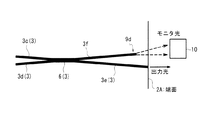
一方、本実施形態にかかる光変調器1では、図1に示すように、3dBカプラ6の出力側の他のポートにはモニタ用光導波路3fが連結されており、このモニタ用光導波路3fは、光変調器(チップ)1の出力端まで延びている。また、モニタ用光導波路3fには、後述するように、減衰部9が設けられている。そして、モニタ用光導波路3fの端部には、モニタPD(フォトディテクタ,バイアス制御用モニタPD,光検出部)10が設けられている。これにより、MZ型光変調器1で変調された出力光のうち、出力側光導波路3eの相補信号として、3dBカプラ6によってモニタ用光導波路3fに導かれ、減衰部9で減衰された後、モニタ光の強度がモニタPD10によって検出されるようになっている。
【0028】
また、図1に示すように、モニタPD10は、バイアス電圧の制御を行なうためのバイアス制御部8に接続されており、モニタPD10によって検出されたモニタ光の強度信号がバイアス制御部8へ送られるようになっている。そして、バイアス制御部8が、モニタ光の強度に基づいてバイアス電圧(DCバイアス電圧)を制御するフィードバック制御を行なうようになっている。つまり、バイアス制御部8は、モニタPD10によって検出された検出値が目標値に近づくように、バイアス電圧のフィードバック制御を行なうようになっている。これにより、光変調器1の動作点電圧の変動が補償されることになる。
【0029】
ところで、上述のように、MZ型光導波路3Aの出力側に3dBカプラ6を設け、この3dBカプラ6に連結されるモニタ用光導波路3fを介してモニタ光を取り出す場合、モニタ光の強度が出力光(信号光)の強度と同じになってしまうため、モニタ光の強度としては大きすぎ、例えば入力光の強度が大きい場合には、モニタPD10に過大電流が流れてしまい、壊れてしまう場合がある。
【0030】
そこで、本実施形態では、モニタ光の強度を適正に調節できるようにすべく、図1に示すように、モニタ用光導波路3fに、モニタ光の出力(パワー)を減衰させる減衰部9が設けられている。これにより、減衰部9によってモニタ光の出力を減衰させ、モニタ光の出力をモニタ用PD10の感度に応じた適正なものにすることができるようになっている。このため、モニタ用PD10では、モニタ用光導波路3fを通じて導かれ、減衰部9によって減衰されたモニタ光の強度が検出されることになる。
【0031】
以下、減衰部9の具体的な構成例について、図2〜図9を参照しながら説明する。
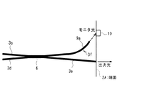
(1)減衰部9を、図2に示すように、曲率半径を小さくした曲がり導波路9a(導波路型減衰器)によって構成する。
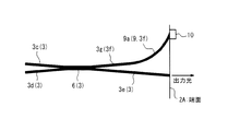
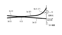
具体的には、図2に示すように、3dBカプラ6のポートから基板2の端面2Aへ向けて直線状に延びる光導波路3gを形成し、この直線状光導波路3gに連なるように、直線状光導波路3gよりも所望の大きさだけ曲率半径を小さくした曲がり導波路9aを形成すれば良い。この場合、直線状光導波路3gと、曲がり導波路9aとからモニタ用光導波路3fが構成される。
【0032】
このように、モニタ用光導波路9を、曲率半径の小さい曲がり導波路9aによって構成すれば、モニタ用光導波路9をモニタ光が伝播する際に曲がり損が生じるため、モニタ用光導波路9を導かれるモニタ光の出力が減衰されることになる。
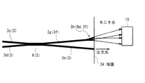
ここで、減衰部9を、曲率半径を小さくした曲がり導波路9aによって構成する場合、図2に示すように、曲がり導波路9aの端部から出射される導波光をモニタ光としてモニタPD10によって検出するようにしても良いし、図3に示すように、曲がり導波路9aの曲がった部分から放射される放射光をモニタ光としてモニタPD10によって検出するようにしても良い。
【0033】
特に、図2に示すように、曲がり導波路9aを通じて導かれる導波光をモニタ光として用いる場合には、モニタPD10は感度の低いものを用いることができ、コストを低く抑えることができるという利点がある。一方、図3に示すように、モニタ光として放射光を用いる場合には、モニタPD10は感度の高いものを用いる必要があるが、取り付けの際の位置合わせは容易であるという利点がある。
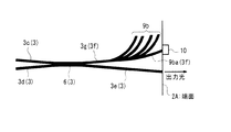
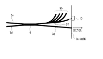
(2)減衰部9を、図4に示すように、2つ以上の分岐光導波路(複数の分岐光導波路,多分岐光導波路,導波路型減衰器)9bによって構成する。
【0034】
具体的には、図4に示すように、3dBカプラ6のポートから基板2の端面2Aへ向けて直線状に延びる光導波路3gを形成し、この直線状光導波路3gに連なるように、2つ以上の分岐光導波路9bを形成すれば良い。この場合、直線状光導波路3gと、2つ以上の分岐光導波路9bのうちの一の分岐光導波路9baとからモニタ用光導波路3fが構成される。
【0035】
このように、モニタ用光導波路3fを、2つ以上の分岐光導波路9bを備えるものとして構成すれば、それぞれの分岐光導波路9bでモニタ光の一部が分岐されるため、モニタ用光導波路3fを構成する一の分岐光導波路9baを導かれるモニタ光の出力が減衰されることになる。
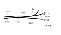
(3)減衰部9を、図5に示すように、1:Nの所定の分岐比で分岐する1:Nカプラ(導波路型カプラ,導波路型減衰器)9cによって構成する。
【0036】
具体的には、図5に示すように、3dBカプラ6のポートから基板2の端面2Aへ向けて直線状に延びる光導波路3gを形成し、この直線状光導波路3gに連なるように、導波路型の1:Nカプラ(導波路型カプラ)9cを形成すれば良い。この場合、直線状光導波路3gと、1:Nカプラ9cの一方のポートに連なる光導波路9caとからモニタ用光導波路3fが構成される。
【0037】
このように、モニタ用光導波路3fを、1:Nカプラ9cを備えるものとして構成すれば、1:Nカプラ9cによってモニタ光の一部が分岐されるため、モニタ用光導波路3fを構成する1:Nカプラ9cの一方のポートに連なる光導波路9caを導かれるモニタ光の出力が減衰されることになる。
(4)減衰部9を、図6,図7に示すように、モニタ用光導波路3fの端部付近に設けられるビーム拡大部(導波路型減衰器)9dによって構成する。
【0038】
ここで、ビーム拡大部9dは、例えば図6に示すように、基板2の端面2A(又は、モニタ光を基板2の側面から出射させる場合は基板の側面)から所定距離の位置に形成されたモニタ用光導波路3fの端部によって構成すれば良い。なお、所定距離は、モニタPD10の感度などを考慮して設定すれば良い。ここでは、モニタPD10は基板2の端面2Aから離れた位置に設けているが、基板2の端面2Aに取り付けるようにしても良い。
【0039】
このように、ビーム拡大部9dを、モニタ用光導波路3fを途中で断線させることによって形成すれば、モニタ用光導波路3fの端部からモニタ光が放射され、基板2の端面2Aから出射されるモニタ光のビーム径が大きくなり、モニタ光の出力が減衰されることになる。また、ビーム径が大きくなるため、モニタPD10を設ける位置のトレランスを大きくすることもできる。
【0040】
また、ビーム拡大部9dは、例えば図7に示すように、モニタ用光導波路3fの端部を2分岐させることによって構成しても良い。つまり、3dBカプラ6のポートから基板2の端面2Aへ向けて直線状に延びる光導波路3gを形成し、この直線状光導波路3gに連なるように、2分岐光導波路3hを形成すれば良い。この場合、直線状光導波路3gと、2分岐光導波路3hとからモニタ用光導波路3fが構成される。ここでは、モニタPD10は基板2の端面2Aから離れた位置に設けているが、基板2の端面2Aに取り付けるようにしても良い。
【0041】
このように、ビーム拡大部9dを、モニタ用光導波路3fの端部を2分岐させることによって構成すれば、モニタ光が2分岐光導波路3hで分岐され、分岐されたそれそれの光導波路からモニタ光が出射されることになるため、モニタ光の出射領域が広がり、モニタ光の出力が減衰されることになる。また、モニタ光の出射領域が広がるため、モニタPD10を設ける位置のトレランスを大きくすることもできる。
(5)減衰部9を、上述の各減衰方法を任意に組み合わせたものとして構成する。
【0042】
つまり、例えば図8に示すように、曲率半径を小さくした曲がり導波路9aを設けるとともに、モニタ用光導波路3fの端部を基板2の端面2Aから所定距離の位置となるように途中で断線させるようにして、減衰部9を構成する。また、例えば図9に示すように、2つ以上の分岐光導波路9bを設けるとともに、モニタ用光導波路3fの端部を基板2の端面2Aから所定距離の位置となるように途中で断線させるようにして、減衰部9を構成する。このように、上述の各減衰方法を組み合わせることによって、モニタ光の出力が大きい場合であっても、確実に減衰させることができるようになる。
【0043】
このように、光変調器1のモニタ用光導波路3fに減衰部9を設けると、図10に示すように、出力側光導波路3eから出射される出力光の出力よりもモニタ光の出力を低く抑えることができるようになる。
したがって、本実施形態にかかる光導波路デバイスとしての光変調器1によれば、マッハツェンダ型光導波路3Aの出力側を3dBカプラ6とし、この3dBカプラ6の出力側の一のポートに連結される光導波路をモニタ用光導波路3fとして、モニタ光を取り出す場合に、モニタ用光導波路3fに減衰器9が設けられているため、モニタ光の強度をモニタPD10の感度に応じた適正な強度に調節することができる。
【0044】
このため、本光導波路デバイス(光変調器)によれば、モニタ光を正確、かつ確実に検出でき、採用しうるモニタPD10の選択の幅が広がり、また、バイアス制御に用いるのに適正な強度のモニタ光が得られるという利点がある。
なお、上述の実施形態では、本発明にかかる光導波路デバイスをマッハツェンダ型の光変調器1に適用しているが、これに限られるものではなく、例えば方向性結合器型光導波路を備える光変調器等の他の導波路構造の光変調器にも適用することができる。
【0045】
また、上述の実施形態では、本発明にかかる光導波路デバイスを光変調器に適用した場合について説明したが、光導波路デバイスはこれに限られるものではなく、本発明は例えば光スイッチ等の他の光導波路デバイスに適用することができる。
また、上述の実施形態では、光変調器から出力される出力光の一部をモニタ光として取り出し、このモニタ光の強度を検出して、バイアス電圧のフィードバック制御を行なうようにしているが、これに限られるものではなく、例えば、検出されたモニタ光の強度を、信号供給部(電源回路,駆動回路を含む)によって印加される電圧のフィードバック制御に用いるものであっても良い。
【0046】
さらに、上述の実施形態では、光変調器を主電極4とバイアス電極5とを備えるものとして構成しているが、これに限られるものではなく、例えば主電極4のみを備えるものとして構成し、主電極4に、データ信号を供給するとともに、バイアス電圧を印加するように構成しても良い。
(第2実施形態の説明)
次に、本発明の第2実施形態にかかる光導波路デバイスについて説明する。
【0047】
以下、本発明の光導波路デバイスを適用して構成されるRZ光変調器[入力光に対してクロック信号とデータ信号を与えてRZ(Return to Zero)信号を生成する光変調器(クロック変調型光変調器)]について、図11〜図17を参照しながら説明する。
本実施形態にかかるRZ光変調器は、例えば長距離光伝送システムにおける光送信器として用いられる。
【0048】
本実施形態では、図11に示すように、RZ光変調器20は、ニオブ酸リチウム(リチウムナイオベート,LiNbO3;LN)を用いた2段のマッハツェンダ型光変調器(MZ型LN光変調器)21,41を備えるものとして構成される。
つまり、RZ光変調器20は、図11に示すように、ニオブ酸リチウム結晶を結晶方位のZ軸方向にカット(Z軸カット)して切り出されたニオブ酸リチウム結晶基板(LN基板)22上に、マッハツェンダ型の第1光導波路(以下、第1光導波路という)23,マッハツェンダ型の第2光導波路(以下、第2光導波路という)24を含む光導波路を形成し、さらに、第1光導波路23の近傍に第1電極(主電極)25及び第1バイアス電極26を形成し、第2光導波路24の近傍に第2電極(主電極)27及び第2バイアス電極28を形成したものとして構成される。
【0049】
なお、RZ光変調器20の前段側に設けられる第1光導波路23,第1電極25,第1バイアス電極26を備えるものとして、マッハツェンダ型の第1光変調器21(クロック信号に変調するため、クロック変調器ともいう)が構成され、RZ光変調器20の後段側に設けられる第2光導波路24,第2電極27,第2バイアス電極28を備えるものとして、マッハツェンダ型の第2光変調器(NRZ(Non Return to Zero)信号に変調するため、NRZ変調器ともいう)41が構成される。
【0050】
なお、ここでは、基板としてニオブ酸リチウム結晶を用いているが、基板は電気光学効果を有するものであれば良く、例えばタンタル酸リチウム(LiTaO2;LT)結晶等の他の強誘電体結晶を用いることもできる。
ここで、LiNbO3結晶やLiTaO2結晶などの電気光学効果を有する基板を用いたRZ光変調器1は、例えばLiNbO3結晶やLiTaO2結晶等からなる基板上の一部に金属膜を形成し、熱拡散させて光導波路を形成するか、又は、金属膜をパターニングした後に、安息香酸中でプロトン交換するなどして光導波路を形成した後、光導波路の近傍に電極を設けることで形成される。
【0051】
具体的には、例えば、LiNbO3結晶を基板に用いる場合、基板上にチタン膜(Ti膜)を所望の光導波路形状に合わせてパターニングし、このようにパターニングした状態で、1050℃で7〜10時間加熱して熱拡散させることによって、光導波路を形成する。
本実施形態では、光導波路は、図11に示すように、入力側光導波路30が対称型の3dBカプラ(光カプラ,導波路型カプラ)29aを介して分岐されて2つの平行な直線状光導波路23b,23cに連結され、さらにこれらの直線状光導波路23b,23cが対称型の3dBカプラ(光カプラ,導波路型カプラ)29bを介してそれぞれ中間光導波路31及びモニタ用光導波路23dに連結されるように形成されている。ここでは、3dBカプラ29a,29bは同じ形のものを用いている。なお、3dBカプラ29a,直線状光導波路23b,23c,3dBカプラ29bによってマッハツェンダ型の第1光導波路23が構成される。
【0052】
また、図11に示すように、中間光導波路31がY分岐光導波路(分岐光導波路)24aを介して分岐されて2つの平行な直線状光導波路24b,24cに連結され、さらにこれらの直線状光導波路24b,24cが対称型の3dBカプラ(光カプラ,導波路型カプラ)29cを介してそれぞれ出力側光導波路32及びモニタ用光導波路24dに連結されるように形成されている。なお、Y分岐光導波路24a,直線状光導波路24b,24c,3dBカプラ29cによってマッハツェンダ型の第2光導波路24が構成される。
【0053】
ここでは、第1光導波路23及び第2光導波路24を構成する3dBカプラ29a〜29cは、導波路型の光カプラ(導波路型カプラ)として形成されている。この3dBカプラ29a〜29cとしては、一般的には方向性結合器型カプラ(3dB方向性結合器)が用いられるが、より好ましくは、波長依存性の少なく、歩留まりの良い交差導波路型カプラ(3dB交差導波路型カプラ)を用いる。
【0054】
このように、本実施形態のRZ光変調器20は、2つのMZ型LN光変調器21,41と、3つの3dBカプラ29a〜29cとを1チップ内に一体に集積化した構造となっている。
また、第1電極25は、図11に示すように、一部が第1光導波路23を構成する一方の直線状光導波路23bと重なるように設けられた信号電極25aと、一部が第1光導波路23を構成する他方の直線状光導波路23cと重なるように設けられた接地電極25bとを備えるものとして構成される。この第1電極25を構成する信号電極25aには、例えば20GHzの周波数の正弦波電気信号(マイクロ波信号,高周波信号)をクロック信号として供給するクロック信号供給部(信号供給部)33が接続されている。
【0055】
そして、第1電極25にクロック信号供給部33からクロック信号を供給して、直線状光導波路23b,23cにクロック信号に応じた電圧(クロック信号電圧,信号電圧)を印加することで、直線状光導波路23b,23cに電界を生じさせて、直線状光導波路23b,23cの屈折率を+Δn,−Δnのように変化させる。これにより、直線状光導波路23b,23cのそれぞれを伝播する光に位相差を生じさせ、これらの位相差の生じた光を3dBカプラ29bで合波干渉させることで、中間光導波路31を介して、第2光導波路24へ向けて、例えば40GHzの光クロック信号[即ち、「1」,「1」,「1」,…のデータ配列の40Gb/sのRZデータ信号(光RZ信号)に変調された変調信号]が出力されるようにしている。
【0056】
なお、本実施形態では、信号電極25aの一方の端部(出力側端部,終端)と接地電極25bの一方の端部(出力側端部,終端)とを抵抗(終端器)で接続することで進行波電極とし、信号電極25aの他方の端部(入力側端部)と接地電極25bの他方の端部(入力側端部)とに接続されるクロック信号供給部33(電源回路や駆動回路を含む)を介してクロック信号を供給して、これに応じた電圧が直線状光導波路23b,23cに印加されるようにしている。このように、第1光変調器21は、高速で駆動することができるようになっている。
【0057】
特に、第1電極25の断面形状を変えることで直線状光導波路23b,23cの実効屈折率を制御し、直線状光導波路23b,23cを伝播する光と、第1電極25に供給されるマイクロ波の速度とを整合させることで、広帯域の光応答特性を得ることができるようになる。
同様に、第2電極27も、図11に示すように、一部が第2光導波路24を構成する一方の直線状光導波路24bと重なるように設けられた信号電極27aと、一部が第2光導波路24を構成する他方の直線状光導波路24cと重なるように設けられた接地電極27bとを備えるものとして構成される。この第2電極27を構成する信号電極27aには、第1光変調器21からの例えば40GHzの光クロック信号に同期したタイミングで、例えば40Gb/sのNRZデータ信号(電気信号)を供給するNRZデータ信号供給部(信号供給部)34が接続されている。
【0058】
そして、第2電極27にNRZデータ信号供給部34からNRZデータ信号を供給して、直線状光導波路24b,24cにNRZデータ信号に応じた電圧(NRZデータ信号電圧,信号電圧)を印加することで、直線状光導波路24b,24cに電界を生じさせて、直線状光導波路24b,24cの屈折率を+Δm,−Δmのように変化させる。これにより、直線状光導波路24b,24cのそれぞれを伝播する光に位相差を生じさせ、これらの位相差の生じた光を3dBカプラ29cで合波干渉させることで、出力側光導波路32を介して、例えば40Gb/sの光RZデータ信号(変調信号)が出力されるようにしている。
【0059】
なお、本実施形態では、信号電極27aの一方の端部(出力側端部,終端)と接地電極27bの一方の端部(出力側端部,終端)とを抵抗(終端器)で接続することで進行波電極とし、信号電極27aの他方の端部(入力側端部)と接地電極27bの他方の端部(入力側端部)とに接続されるNRZデータ信号供給部34(電源回路や駆動回路を含む)を介してNRZデータ信号を供給して、これに応じた電圧が直線状光導波路24b,24cに印加されるようにしている。このように、第2光変調器41は、高速で駆動することができるようになっている。
【0060】
特に、第2電極27の断面形状を変えることで直線状光導波路24b,24cの実効屈折率を制御し、直線状光導波路24b,24cを伝播する光と、第2電極27に供給されるマイクロ波の速度とを整合させることで、広帯域の光応答特性を得ることができるようになる。
また、第1バイアス電極26は、図11に示すように、一部が第1光導波路23を構成する一方の直線状導波路23bと重なるように設けられた電極26aと、一部が第1光導波路23を構成する他方の直線状導波路23cと重なるように設けられた接地電極26bとを備えるものとして構成される。この第1バイアス電極26には第1バイアス制御部(例えばバイアス制御回路)35が接続されている。
【0061】
そして、第1バイアス電極26に第1バイアス制御部35を通じてバイアス電圧(DC電圧)を供給することで、第1光導波路23に対してバイアス電圧(DC電圧)が印加されるようになっている。
ここでは、後述するように、第1バイアス制御部35によって、モニタ光の強度に基づいてバイアス電圧を制御するフィードバック制御を行なうことで、第1光変調器21の動作点電圧の変動を補償している。
【0062】
同様に、第2バイアス電極28は、図11に示すように、一部が第2光導波路24を構成する一方の直線状導波路24bと重なるように設けられた電極28aと、一部が第2光導波路24を構成する他方の直線状導波路24cと重なるように設けられた接地電極28bとを備えるものとして構成される。この第2バイアス電極28には第2バイアス制御部(バイアス制御回路)36が接続されている。
【0063】
そして、第2バイアス電極28に第2バイアス制御部36を通じてバイアス電圧(DC電圧)を供給することで、第2光導波路24に対してバイアス電圧(DC電圧)が印加されるようになっている。
ここでは、後述するように、第2バイアス制御部36によって、モニタ光の強度に基づいてバイアス電圧を制御するフィードバック制御を行なうすることで、第2光変調器41の動作点電圧の変動を補償している。
【0064】
本実施形態では、Z軸カットのニオブ酸リチウム結晶基板22を用いており、Z軸方向の電界による屈折率変化を利用するため、第1電極25,第1バイアス電極26は、第1光導波路23の直線状導波路23b,23cの真上に形成され、第2電極27,第2バイアス電極28は第2光導波路24の直線状導波路24b,24cの真上に形成される。
【0065】
このように、本実施形態では、第1電極25,第1バイアス電極26,第2電極27,第2バイアス電極28は、直線状導波路23b,23c,24b,24cの真上にパターニングするため、直線状光導波路23b,23c,24b,24c中を伝搬する光が各電極25,26,27,28によって吸収されてしまうおそれがある。これを防ぐために、本実施形態では、LN基板22と各電極25,26,27,28との間にバッファ層を形成している。このバッファ層は例えばSiO2膜として形成すれば良く、その厚さは、0.2〜1μm程度とすれば良い。
【0066】
このため、本RZ光変調器20は、第1,第2電極25,27及び第1,第2バイアス電極26,28と基板22との間に、基板22の厚さと比べて厚さの薄いバッファ層を積層したものとして構成される。
なお、本実施形態では、第1電極25,第2電極27,第1バイアス電極26,第2バイアス電極28は、いずれも1つの信号電極を有するシングル電極とし、RZ光変調器20をシングル駆動型の光変調器として構成しているが、これに限られるものではない。例えば、駆動電圧を低減するためには、2つの信号電極を有するデュアル電極とし、デュアル駆動型の光変調器として構成すれば良い。
【0067】
ところで、本実施形態では、図11に示すように、第1光導波路23の出力側には3dBカプラ29bが設けられており、この3dBカプラ29bの出力側の一のポートに中間光導波路31を介して第2光導波路24の入力側、即ち、第2光導波路24のY分岐光導波路24aが連結されている。つまり、第1光変調器21と第2光変調器41とは、光導波方向に沿って直列に連結されている。
【0068】
なお、ここでは、前後に2つの光変調器21,41を直列に連結しているが、光変調器の数はこれに限られるものではない。つまり、複数の光変調器を直列に連結しても良い。この場合、モニタPD,信号供給部も複数設けることになる。
これにより、図示しない光源(半導体レーザ)からの入力光が、入力側光導波路30,3dBカプラ29aを介して第1光導波路23に導入され、この第1光導波路23を伝播する際に所望のクロック信号(電気信号)に基づいて変調された後、第1光導波路23の出力側に設けられる3dBカプラ29b及び3dBカプラ29bの出力側の一のポートに連結されている中間光導波路31を介して第2光導波路24へ導かれ、さらに第2光導波路24でNRZデータ信号(電気信号)に基づいて変調され、3dBカプラ29c及び3dBカプラ29cの出力側の一のポートに連結されている出力側光導波路32を介して、変調された出力光(信号光,光NR信号)が出力されるようになっている。
【0069】
本実施形態では、図11に示すように、第1光導波路23の出力側に設けられる3dBカプラ29bの他のポートには第1モニタ用光導波路23dが連結されており、この第1モニタ用光導波路23dは、RZ光変調器(チップ)20の出力端まで延びている。そして、第1モニタ用光導波路23dの端部には、第1モニタPD(フォトディテクタ,第1バイアス制御用モニタPD,光検出部,光検出器)37が設けられている。これにより、第1光変調器21で変調された光の一部が、3dBカプラ29bによってモニタ光として分岐されて第1モニタ用光導波路23dに導かれ、モニタ光の強度が第1モニタPD37によって検出されるようになっている。
【0070】
また、図11に示すように、第1モニタPD37は、バイアス電圧の制御を行なうための第1バイアス制御部35に接続されており、第1モニタPD37によって検出されたモニタ光の強度信号が第1バイアス制御部35へ送られるようになっている。そして、第1バイアス制御部35が、モニタ光の強度に基づいてバイアス電圧(DCバイアス電圧)を制御するフィードバック制御を行なうようになっている。つまり、第1バイアス制御部35は、第1モニタPD37によって検出された検出値が目標値に近づくように、バイアス電圧のフィードバック制御を行なうようになっている。これにより、第1光変調器21の動作点電圧の変動が補償されることになる。
【0071】
一方、第2光導波路24の出力側に設けられる3dBカプラ29cの他のポートには第2モニタ用光導波路24dが連結されており、この第2モニタ用光導波路24dは、RZ光変調器(チップ)20の出力端まで延びている。そして、第2モニタ用光導波路24dの端部には、第2モニタPD(フォトディテクタ,第2バイアス制御用モニタPD,光検出部,光検出器)38が設けられている。これにより、第2光変調器41で変調された光の一部が、3dBカプラ29cによってモニタ光として分岐されて第2モニタ用光導波路24dに導かれ、モニタ光の強度が第2モニタPD38によって検出されるようになっている。
【0072】
また、図11に示すように、第2モニタPD38は、バイアス電圧の制御を行なうための第2バイアス制御部36に接続されており、第2モニタPD38によって検出されたモニタ光の強度信号が第2バイアス制御部36へ送られるようになっている。そして、第2バイアス制御部36が、モニタ光の強度に基づいて、バイアス電圧(DCバイアス電圧)のフィードバック制御を行なうようになっている。つまり、第2バイアス制御部36は、第2モニタPD38によって検出された検出値が目標値に近づくように、バイアス電圧のフィードバック制御を行なうようになっている。これにより、第2光変調器41の動作点電圧の変動が補償されることになる。
【0073】
このように、本実施形態では、第1光変調器21によって変調された光(信号光)の一部をモニタ光として取り出し、このモニタ光の強度を第1モニタPD37で検出するとともに、これとは独立に、第2光変調器41によって変調された光(信号光)の一部をモニタ光として取り出し、このモニタ光の強度を第2モニタPD38によって検出するようにしている。
【0074】
そして、第1モニタPD37と、第2モニタPD38とを、それぞれ別個のバイアス制御部35,36に接続している。つまり、第1モニタPD37は、第1光変調器21のバイアス制御を行なうための第1バイアス制御部35に接続し、第2モニタPD38は、第2光変調器41のバイアス制御を行なうための第2バイアス制御部36に接続している。
【0075】
これにより、第1光変調器21の動作点電圧の変動を補償するために行なわれるバイアス電圧のフィードバック制御と、第2光変調器41の動作点電圧の変動を補償するために行なわれるバイアス電圧のフィードバック制御とが、それぞれ独立して行なわれるようにしている。
したがって、本実施形態にかかる光導波路デバイスとしてのRZ光変調器20によれば、それぞれの光変調器21,41毎に設けられた第1モニタPD37,第2モニタPD38によって、各光変調器21,41によって変調された光をそれぞれ独立にモニタするため、それぞれの光変調器21,41のバイアス制御が容易、かつ、正確に行なえるようになるという利点がある。
【0076】
なお、本第2実施形態では、第1光変調器21及び第2光変調器41は、いずれもマッハツェンダ型の光変調器として構成しているが、これに限られるものではなく、例えば方向性結合器型の光変調器として構成しても良い。
また、本第2実施形態では、第2光変調器21の入力側をY分岐光導波路24aとしているが、これに限られるものではなく、例えば3dBカプラとして構成しても良い。
【0077】
さらに、本第2実施形態では、第1光変調器21の入射側及び出射側に3dBカプラ29a,29bを設けており、さらに、第2光変調器41の出射側にも3dBカプラ29cを設けているが、これに限られるものではなく、例えばY分岐光導波路として構成しても良い。
(第2実施形態の第1変形例の説明)
次に、本発明の第2実施形態の第1変形例にかかる光導波路デバイスとしてのRZ光変調器について、図12を参照しながら説明する。
【0078】
本第1変形例にかかるRZ光変調器は、上述の第2実施形態のものと比べ、第1光導波路23の出力側に設けられる3dBカプラ29bに連結される第1モニタ用光導波路の構成と、第1光変調器21のバイアス制御に用いられる第1モニタPD37を設ける位置が異なる。
つまり、本第1変形例では、図12に示すように、第1光導波路23の出力側に設けられる3dBカプラ29bの出力側の他のポートに連結される第1モニタ用光導波路23dを、RZ光変調器50(チップ)の側面まで延びるように形成し、このRZ光変調器50の側面まで延びる第1モニタ用光導波路23dの端部に第1モニタPD(光検出部)37を設けている。
【0079】
なお、その他の構成は上述の第2実施形態のものと同様であるため、ここでは説明を省略する。
このように、本第1変形例によれば、上述の第2実施形態の構成による効果に加え、第1モニタPD37をRZ光変調器20の側面に設けることができるため、第1モニタPD37,第2モニタPD38の配設位置の自由度が大きくなるという利点がある。
(第2実施形態の第2変形例の説明)
次に、本発明の第2実施形態の第2変形例にかかる光導波路デバイスとしてのRZ光変調器について、図13を参照しながら説明する。
【0080】
本第2変形例にかかるRZ光変調器は、上述の第2実施形態のものと比べ、第2光変調器41から出力される光のモニタ方法が異なる。このため、第2光導波路24の出力側の構成が異なり、また、第2光導波路24のバイアス制御に用いられる第2モニタPD(光検出部)38を設ける位置が異なる。
つまり、図13に示すように、本第2変形例にかかるRZ光変調器60では、第2光導波路24の出力側をY分岐光導波路61とし、このY分岐光導波路61を出力側光導波路32に連結して、第2光導波路24からの出力光がY分岐光導波路61,出力側光導波路32を介して出力されるようにしている。そして、OFF状態にY分岐光導波路61の分岐部分から放射される放射光をモニタ光として用いるようにしている。このため、第2モニタPD38は、RZ光変調器(チップ)60の出力側の端面であって、Y分岐光導波路61の分岐部分からの放射光の強度を検出できるような位置に設けている。
【0081】
なお、その他の構成は上述の第2実施形態のものと同様であるため、ここでは説明を省略する。
このように、本第2変形例によれば、上述の第2実施形態の構成による効果に加え、第2モニタPD38の配設位置のトレランスを大きくすることができる。
(第2実施形態の第3変形例の説明)
次に、本発明の第2実施形態の第3変形例にかかる光導波路デバイスとしてのRZ光変調器について、図14(A),(B)を参照しながら説明する。なお、図14(A)は模式的平面図であり、図14(B)は模式的断面図である。
【0082】
本第3変形例にかかるRZ光変調器は、上述の第2実施形態のものと比べ、第1光変調器21及び第2光変調器41から出力される光のモニタ方法が異なる。このため、第1光導波路23及び第2光導波路24の出力側の構成が異なり、また、第1光導波路23のバイアス制御に用いられる第1モニタPD(光検出部)37を設ける位置や第2光導波路24のバイアス制御に用いられる第2モニタPD(光検出部)38を設ける位置が異なる。
【0083】
つまり、図14(A),(B)に示すように、本第3変形例にかかるRZ光変調器70では、第1光導波路23の出力側をY分岐光導波路71とし、このY分岐光導波路71を中間光導波路31を介して第2光導波路24に連結して、第1光導波路23からの出力光がY分岐光導波路71,中間光導波路31を介して第2光導波路24へ向けて出力されるようにしている。そして、OFF状態にY分岐光導波路71の分岐部分から放射される放射光をモニタ光として用いるようにしている。このため、第1モニタPD37は、RZ光変調器(チップ)70の出力側の端面であって、Y分岐光導波路71の分岐部分からの放射光の強度を検出できるような位置に設けている。
【0084】
また、図14(A),(B)に示すように、第2光導波路24の出力側をY分岐光導波路72とし、このY分岐光導波路72を出力側光導波路32に連結して、第2光導波路24からの出力光がY分岐光導波路72,出力側光導波路32を介して出力されるようにしている。そして、OFF状態にY分岐光導波路72の分岐部分から放射される放射光をモニタ光として用いるようにしている。このため、第2モニタPD38は、RZ光変調器(チップ)70の出力側の端面であって、Y分岐光導波路72の分岐部分からの放射光の強度を検出できるような位置に設けている。
【0085】
特に、図14(B)に示すように、OFF状態に第1光導波路23のY分岐光導波路71の分岐部分から放射される放射光は、RZ光変調器(チップ)70の厚さ方向に向けて斜めにチップ表面から離れていくように伝播するため、RZ光変調器70の出力側の端面において、基板22の底面に近い位置から出射することになる。このため、第1モニタPD37は、RZ光変調器70の出力側の端面の基板22の底面に近い位置に設けることになる。なお、第1モニタPD37の配設位置は、第1光導波路23のY分岐光導波路71の分岐部分の位置からRZ光変調器70の出力側の端面までの距離に応じて決められる。
【0086】
一方、図14(B)に示すように、OFF状態に第2光導波路24のY分岐光導波路72の分岐部分から放射される放射光は、Y分岐光導波路72の分岐部分からRZ光変調器(チップ)70の出力側の端面までの距離が近いため、RZ光変調器70の出力側の端面において、基板22の表面に近い位置から出射することになる。このため、第2モニタPD38は、RZ光変調器70の出力側の端面において、基板22の表面に近い位置に設けることになる。なお、第2モニタPD38の配設位置は、第2光導波路24のY分岐光導波路72の分岐部分の位置からRZ光変調器70の出力側の端面までの距離に応じて決められる。
【0087】
このように、RZ光変調器70の出力側の端面において、基板22の表面に近い方の位置に第2モニタPD38が設けられ、第2モニタPD38よりも基板22の表面から離れた位置(即ち、基板の底面に近い位置)に第1モニタPD37が設けられることになる。つまり、2つのモニタPD37,38は、対応するY分岐光導波路71,72の分岐部分から放射される放射光の強度を検出しうるように、基板22の出力側端面の厚さ方向に位置をずらして配設されている。
【0088】
なお、本第3変形例では、第1光導波路23の入力側の構成も異なるものとしている。つまり、本第3変形例では、第1光導波路23の入力側をY分岐光導波路73とし、このY分岐光導波路73を介して入力側光導波路30を第1光導波路23に連結するようにしている。なお、その他の構成は上述の第2実施形態のものと同様であるため、ここでは説明を省略する。
【0089】
このように、本第3変形例によれば、上述の第2実施形態の構成による効果に加え、第2モニタPD38の配設位置のトレランスを大きくすることができる。また、モニタ光を取り出すのにモニタ用光導波路を形成する必要がないため、RZ光変調器70の全体の大きさをコンパクトにすることができる。
(第2実施形態の第4変形例の説明)
次に、本発明の第2実施形態の第4変形例にかかる光導波路デバイスとしてのRZ光変調器について、図15を参照しながら説明する。
【0090】
本第4変形例にかかるRZ光変調器は、上述の第2実施形態のものと比べ、第1光変調器23の出力側の構成及び第2光変調器24の出力側の構成が異なる。つまり、図15に示すように、本第4変形例にかかるRZ光変調器80では、第1光導波路23の出力側をY分岐光導波路81とし、このY分岐光導波路81に、1:Nの所定の分岐比で分岐する導波路型の1:Nカプラ(例えば1:10カプラ,導波路型カプラ)82を連結している。そして、1:Nカプラ82の一のポート(出力の小さい方)には、RZ光変調器(チップ)80の出力側の端面まで延びるように形成されている第1モニタ用光導波路23dが連結されており、この第1モニタ用光導波路23dの端部に第1モニタPD(光検出部)37が配設されている。
【0091】
一方、図15に示すように、1:Nカプラ82の他のポート(出力の大きい方)には、第2光導波路24の入力側のY分岐光導波路24aが連結されており、第1光導波路23からの出力光がY分岐光導波路81,1:Nカプラ82を介して第2光導波路24へ向けて出力されるようにしている。
また、図15に示すように、第2光導波路24の出力側もY分岐光導波路83とし、このY分岐光導波路83に、1:Nの所定の分岐比で分岐する導波路型の1:Nカプラ(例えば1:10カプラ,導波路型カプラ)84を連結している。そして、1:Nカプラ84の一のポート(出力の小さい方)には、RZ光変調器(チップ)80の出力側の端面まで延びるように形成されている第2モニタ用光導波路24dが連結されており、この第2モニタ用光導波路24dの端部に第2モニタPD(光検出部)38が配設されている。
【0092】
一方、図15に示すように、1:Nカプラ84の他のポート(出力の大きい方)には、出力側光導波路32が連結されており、第2光導波路24からの出力光がY分岐光導波路83,1:Nカプラ84,出力側光導波路32を介して出力されるようにしている。
なお、本第4変形例では、第1光導波路23の入力側の構成も異なるものとしている。つまり、本第4変形例では、第1光導波路23の入力側をY分岐光導波路85とし、このY分岐光導波路85を介して入力側光導波路30を第1光導波路23に連結するようにしている。なお、その他の構成は上述の第2実施形態のものと同様であるため、ここでは説明を省略する。
【0093】
このように、本第4変形例によれば、出力光は1:Nの比率で弱くなるため、1:Nカプラの分岐比を適切に設計することにより、分岐後のモニタ光導波路23d,24dを伝播するモニタ光を減衰させるために導波路形状を工夫する必要がなく、導波路構造の設計が容易であるという利点がある。
(第2実施形態の第5変形例の説明)
次に、本発明の第2実施形態の第5変形例にかかる光導波路デバイスとしてのRZ光変調器について、図16を参照しながら説明する。
【0094】
本第5変形例にかかるRZ光変調器は、上述の第2実施形態のものと比べ、第1光変調器21の出力側の構成及び第2光変調器41の出力側の構成が異なり、さらに、第2光変調器41の後段に、3段目のマッハツェンダ型光変調器として、マッハツェンダ型の可変減衰器が設けられている点が異なる。このようなRZ光変調器を可変減衰器集積型RZ光変調器という。
【0095】
つまり、図16に示すように、本第5変形例にかかるRZ光変調器90では、第1光導波路23の出力側をY分岐光導波路91とし、このY分岐光導波路91に、1:Nの所定の分岐比で分岐する導波路型の1:Nカプラ(例えば1:10カプラ,導波路型カプラ)92を連結している。そして、1:Nカプラ92の一のポート(出力の小さい方)には、RZ光変調器(チップ)90の出力側の端面まで延びるように形成されている第1モニタ用光導波路23dが連結されており、この第1モニタ用光導波路23dの端部に第1モニタPD(光検出部)37が配設されている。
【0096】
一方、図16に示すように、1:Nカプラ92の他のポート(出力の大きい方)には、第2光導波路24の入力側のY分岐光導波路24aが連結されており、第1光導波路23からの出力光がY分岐光導波路91,1:Nカプラ92を介して第2光導波路24へ向けて出力されるようにしている。
また、図16に示すように、第2光導波路24の出力側もY分岐光導波路93とし、このY分岐光導波路93に、1:Nの所定の分岐比で分岐する導波路型の1:Nカプラ(例えば1:10カプラ,導波路型カプラ)94を連結している。そして、1:Nカプラ94の一のポート(出力の小さい方)には、RZ光変調器(チップ)90の出力側の端面まで延びるように形成されている第2モニタ用光導波路24dが連結されており、この第2モニタ用光導波路24dの端部に第2モニタPD(光検出部)38が配設されている。
【0097】
一方、1:Nカプラ94の他のポート(出力の大きい方)には、図16に示すように、マッハツェンダ型の可変減衰器95が連結されている。つまり、第2光変調器41の後段には、マッハツェンダ型の可変減衰器95が連結されている。このため、可変減衰器95には、第2光導波路24からの出力光がY分岐光導波路93,1:Nカプラ94を介して入力されるようになっている。
【0098】
ここで、可変減衰器95は、図16に示すように、入力側のY分岐光導波路96a,2つの平行な直線状光導波路96b,96c,出力側のY分岐光導波路96dを備えるマッハツェンダ型の光導波路96と、電極97と、バイアス電極98とを備えるものとして構成される。そして、電極97を介して直線状光導波路96b,96cに所定の直流電圧(DC電圧)を印加して、直線状光導波路96b,96cの屈折率を変化させることで、直線状光導波路96b,96cの透過率を変化させ、直線状光導波路96b,96c内を伝播する光(信号光)の出力(パワー)を減衰させるようになっている。このため、電極97には電圧供給部(電源回路や駆動回路を含む)が接続されている。
【0099】
また、可変減衰器95の出力側のY分岐光導波路96dには、1:Nの所定の分岐比で分岐する導波路型の1:Nカプラ(例えば1:10カプラ,導波路型カプラ)99が連結されている。この1:Nカプラ99の一のポート(出力の小さい方)には、RZ光変調器(チップ)90の出力側の端面まで延びるように形成されている第3モニタ用光導波路100が連結されており、この第3モニタ用光導波路100の端部に第3モニタPD(光検出部)101が配設されている。
【0100】
そして、第3モニタPD101によって検出されたモニタ光の強度に基づいて、バイアス電圧(DCバイアス電圧)のフィードバック制御が行なわれるようになっている。つまり、第2モニタPD101によって検出された検出値が目標値に近づくように、バイアス電圧のフィードバック制御を行なうようになっている。このため、第2モニタPD101には第3バイアス制御部(バイアス制御回路)が接続されている。
【0101】
このように、電極97に所定のDC電圧を印加するとともに、任意に設定しうる目標値に近づくようにバイアス電圧を印加することで、直線状光導波路96b,96cに印加されるDC電圧を可変制御して、出力光のパワーを調節できるようにしている。
一方、図16に示すように、1:Nカプラ99の他のポート(出力の大きい方)には、出力側光導波路32が連結されており、可変減衰器95からの出力光が1:Nカプラ99,出力側光導波路32を介して出力されるようにしている。
【0102】
なお、本第5変形例では、第1光導波路23の入力側の構成も異なるものとしている。つまり、本第5変形例では、第1光導波路23の入力側をY分岐光導波路102とし、このY分岐光導波路102を介して入力側光導波路30を第1光導波路23に連結するようにしている。なお、その他の構成は上述の第2実施形態のものと同様であるため、ここでは説明を省略する。
【0103】
このように、本第5変形例によれば、上述の第4変形例の場合と同様に、出力光は1:Nの比率で弱くなるため、1:Nカプラの分岐比を適切に設計することにより、分岐後のモニタ光導波路23d,24dを伝播するモニタ光を減衰させるために導波路形状を工夫する必要がなく、導波路構造の設計が容易であるという利点がある。
【0104】
なお、図17に示すように、上述の第2実施形態にかかる光導波路デバイスとしてのRZ光変調器20のモニタ用光導波路23d、24dに、上述の第1実施形態のモニタ用光導波路を伝播するモニタ光を減衰させる減衰部9を設けるのも好ましい。これにより、上述の第2実施形態及びその各変形例の構成における効果に加え、モニタ光を正確、かつ確実に検出でき、採用しうるモニタPD10の選択の幅が広がり、また、バイアス制御に用いるのに適正な強度のモニタ光が得られるようになる。なお、第2実施形態の各変形例において、モニタ用光導波路を伝播するモニタ光を減衰させる必要がある場合には、同様にモニタ用光導波路に減衰部9を設ければよい。
【0105】
なお、上述の各実施形態及び各変形例では、モニタ用光導波路を通じてモニタ光を取り出す場合にモニタ用PDを基板の端面に取り付けるようにしているものがあるが、これに限られるものではなく、モニタ用光導波路を導かれるモニタ光の強度に応じて、基板の端面から所定距離だけ離した位置(例えば筐体)に取り付けるようにしても良い。
[付記]
(付記1) 電気光学効果を有する基板と、
前記基板上に直列に形成される複数のマッハツェンダ型又は方向性結合器型の光導波路と、
前記複数の光導波路毎に独立して設けられる複数の電極と、
前記複数の光導波路から出射される光の強度をそれぞれ独立して検出する複数の光検出部とを備えることを特徴とする、光導波路デバイス。
【0106】
(付記2) 前記複数の光導波路のそれぞれの出力側に設けられる複数の導波路型カプラと、
前記複数の導波路型カプラの一方のポートに連結される複数のモニタ用光導波路とを備え、
前記複数の光検出部が、それぞれ対応するモニタ用光導波路を通じて導かれるモニタ光の強度を検出することを特徴とする、付記1記載の光導波路デバイス。
【0107】
(付記3) 前記導波路型カプラが3dBカプラであり、
前記モニタ用光導波路が、前記3dBカプラの一方のポートに連結されることを特徴とする、付記2記載の光導波路デバイス。
(付記4) 前記導波路型カプラが1:Nカプラであり、
前記モニタ用光導波路が、前記1:Nカプラの一方のポートに連結されることを特徴とする、付記2記載の光導波路デバイス。
【0108】
(付記5) 前記1:Nカプラが、1:10カプラであることを特徴とする、付記4記載の光導波路デバイス。
(付記6) 前記複数の光導波路のうち一の光導波路の出力側に設けられる1又は複数の導波路型カプラと、
前記複数の光導波路のうち他の光導波路の出力側に設けられる1又は複数のY分岐光導波路と、
前記導波路型カプラの一方のポートに連結される1又は複数のモニタ用光導波路とを備え、
前記複数の光検出部のうちの一の光検出部は、対応するモニタ用光導波路を通じて導かれるモニタ光の強度を検出し、他の光検出部は、対応するY分岐光導波路の分岐部分から放射された放射光の強度を検出することを特徴とする、付記1記載の光導波路デバイス。
【0109】
(付記7) 前記複数の光導波路が、いずれも出力側にY分岐光導波路を有するマッハツェンダ型光導波路であり、
前記複数の光検出部が、対応する前記Y分岐光導波路の分岐部分から放射される放射光の強度を検出しうるように、前記基板の出力側端面の厚さ方向に位置をずらして配設されていることを特徴とする、付記1記載の光導波路デバイス。
【0110】
(付記8) 前記複数のモニタ用光導波路のうち一のモニタ用光導波路が、前記基板の側面まで延びるように形成され、
前記複数の光検出部のうち一の光検出部が、前記一のモニタ用光導波路から出力される光を検出しうるように前記基板の側面に設けられていることを特徴とする、付記2〜5のいずれか1項に記載の光導波路デバイス。
【0111】
(付記9) 前記基板が、リチウムナイオベートにより構成されることを特徴とする、付記1〜8のいずれか1項に記載の光導波路デバイス。
(付記10) 電気光学効果を有する基板と、
前記基板上に直列に形成される第1,第2マッハツェンダ型光導波路と、
前記第1マッハツェンダ型光導波路に設けられ、クロック信号が供給される第1信号電極と、
前記第2マッハツェンダ型光導波路に設けられ、データ信号が供給される第2信号電極と、
前記第1マッハツェンダ型光導波路に設けられ、バイアス電圧を印加される第1バイアス電極と、
前記第2マッハツェンダ型光導波路に設けられ、バイアス電圧を印加される第2バイアス電極と、
前記第1マッハツェンダ型光導波路から出力される光の強度を検出する第1モニタPDと、
前記第2マッハツェンダ型光導波路から出力される光の強度を検出する第2モニタPDとを備えることを特徴とする、光変調器。
【0112】
(付記11) 前記第1マッハツェンダ型光導波路又は前記第2マッハツェンダ型光導波路の出力側に設けられる3dBカプラと、
前記第1マッハツェンダ型光導波路又は前記第2マッハツェンダ型光導波路から出力される光のうち前記3dBカプラによって分岐された光をモニタ光として前記第1モニタPD又は前記第2モニタPDへ導くモニタ用光導波路と、
前記モニタ用光導波路を伝播するモニタ光を減衰させる減衰部とを備えることを特徴とする、付記10記載の光変調器。
【0113】
(付記12) 電気光学効果を有する基板と、
前記基板上に形成される光導波路と、
前記光導波路に設けられる電極と、
前記光導波路から出力される光の一部をモニタ光として導くモニタ用光導波路と、
前記モニタ用光導波路に設けられ、モニタ光を減衰させる減衰部と、
前記モニタ用光導波路を通じて導かれ、前記減衰部によって減衰されたモニタ光の強度を検出する光検出部とを備えることを特徴とする、光導波路デバイス。
【0114】
(付記13) 前記光導波路が、マッハツェンダ型光導波路であり、
前記マッハツェンダ型光導波路の出力側に3dBカプラを備えることを特徴とする、付記12記載の光導波路デバイス。
(付記14) 前記減衰部が、前記モニタ用光導波路を構成する曲率半径を小さくした曲がり導波路によって構成されることを特徴とする、付記12又は13記載の光導波路デバイス。
【0115】
(付記15) 前記減衰部が、前記モニタ用光導波路を構成する2つ以上の分岐部によって構成されることを特徴とする、付記12又は13記載の光導波路デバイス。
(付記16) 前記減衰部が、前記モニタ用光導波路を構成する1:Nカプラによって構成されることを特徴とする、付記12又は13記載の光導波路デバイス。
【0116】
(付記17) 前記減衰部が、前記モニタ用光導波路の端部付近に設けられるビーム拡大部によって構成されることを特徴とする、付記12〜16のいずれか1項に記載の光導波路デバイス。
(付記18) 前記モニタ用光導波路の端部付近にビーム拡大部を備えることを特徴とする、付記12〜16のいずれか1項に記載の光導波路デバイス。
【0117】
(付記19) 前記ビーム拡大部が、前記モニタ用光導波路の端部を前記基板の端面又は側面から所定距離の位置とすることによって構成されることを特徴とする、付記17又は18記載の光導波路デバイス。
(付記20) 前記ビーム拡大部が、前記モニタ用光導波路の端部を2分岐させることによって構成されることを特徴とする、付記17又は18記載の光導波路デバイス。
【0118】
(付記21) 電気光学効果を有する基板と、
前記基板上に直列に形成される複数のマッハツェンダ型又は方向性結合器型の光導波路と、
前記複数の光導波路毎に独立して設けられる複数の電極と、
前記複数の光導波路から出射される光の強度をそれぞれ独立して検出する複数の光検出部と、
前記複数の光検出部のうちの一の光検出部で検出された光の強度に基づいて、前記一の光検出部に対応する前記光導波路に設けられる前記電極に印加されるバイアス電圧を制御するバイアス制御部とを備えることを特徴とする、光導波路デバイス。
【0119】
【発明の効果】
以上詳述したように、本発明の光導波路デバイス及び光デバイスによれば、モニタ用光導波路を介してモニタ光を取り出すため、モニタ光を正確、かつ確実に検出でき、また、モニタ部として採用しうる部品の選択の幅が広がり、また、バイアス制御に用いるのに適正な強度のモニタ光が得られるという利点がある。
【0120】
また、本発明の光導波路デバイス及び光デバイスによれば、複数のマッハツェンダ型干渉計のために設けられたモニタ部によって、それぞれ独立にモニタ光を検出し、これに基づいてバイアス制御を行なうため、バイアス制御を容易、かつ、正確に行なえるという利点がある。
【図面の簡単な説明】
【図1】本発明の第1実施形態にかかる光導波路デバイスとしての光変調器の全体構成を示す模式図である。
【図2】本発明の第1実施形態にかかる光導波路デバイスとしての光変調器に備えられる減衰部の構成例を模式的に示す拡大図である。
【図3】本発明の第1実施形態にかかる光導波路デバイスとしての光変調器に備えられる減衰部の他の構成例を模式的に示す拡大図である。
【図4】本発明の第1実施形態にかかる光導波路デバイスとしての光変調器に備えられる減衰部の他の構成例を模式的に示す拡大図である。
【図5】本発明の第1実施形態にかかる光導波路デバイスとしての光変調器に備えられる減衰部の他の構成例を模式的に示す拡大図である。
【図6】本発明の第1実施形態にかかる光導波路デバイスとしての光変調器に備えられる減衰部の他の構成例を模式的に示す拡大図である。
【図7】本発明の第1実施形態にかかる光導波路デバイスとしての光変調器に備えられる減衰部の他の構成例を模式的に示す拡大図である。
【図8】本発明の第1実施形態にかかる光導波路デバイスとしての光変調器に備えられる減衰部の他の構成例を模式的に示す拡大図である。
【図9】本発明の第1実施形態にかかる光導波路デバイスとしての光変調器に備えられる減衰部の他の構成例を模式的に示す拡大図である。
【図10】本発明の第1実施形態にかかる光導波路デバイスとしての光変調器における信号光及びモニタ光の光出力を示す図である。
【図11】本発明の第2実施形態にかかる光導波路デバイスとしてのRZ光変調器の全体構成を示す模式図である。
【図12】本発明の第2実施形態の第1変形例にかかる光導波路デバイスとしてのRZ光変調器の全体構成を示す模式図である。
【図13】本発明の第2実施形態の第2変形例にかかる光導波路デバイスとしてのRZ光変調器の全体構成を示す模式図である。
【図14】本発明の第2実施形態の第3変形例にかかる光導波路デバイスとしてのRZ光変調器の全体構成を示す模式図である。
【図15】本発明の第2実施形態の第4変形例にかかる光導波路デバイスとしてのRZ光変調器の全体構成を示す模式図である。
【図16】本発明の第2実施形態の第5変形例にかかる光導波路デバイスとしてのRZ光変調器の全体構成を示す模式図である。
【図17】本発明の第2実施形態の他の変形例にかかる光導波路デバイスとしてのRZ光変調器の全体構成を示す模式図である。
【図18】バイアス制御に用いられるモニタ光をモニタ用光導波路を用いて取り出す方法について説明するための図である。
【図19】モニタ用光導波路を用いてモニタ光を取り出す場合の課題を説明するための図であって、信号光及びモニタ光の光出力を示す図である。
【図20】RZ光変調器におけるバイアス制御を説明するための図である。
【符号の説明】
1 MZ型LN光変調器
2 基板
2A 端面
3A 光導波路(MZ型光導波路)
3 光導波路
3a 入力側光導波路
3b Y分岐光導波路
3c,3d 直線状光導波路
3e 出力側光導波路
3f モニタ用光導波路
3g 直線状光導波路
3h 2分岐光導波路
4 主電極
4a 信号電極
4b 接地電極
5 バイアス電極
5a 電極
5b 接地電極
6 3dBカプラ(導波路型カプラ)
7 データ信号供給部(信号供給部)
8 バイアス制御部
9 減衰部
9a 曲がり導波路
9b 分岐光導波路(複数の分岐光導波路,多分岐光導波路)
9c 1:Nカプラ
9d ビーム拡大部
10 モニタPD(フォトディテクタ,バイアス制御用モニタPD,光検出部)
20 RZ光変調器
21,41 マッハツェンダ型光変調器(MZ型LN光変調器)
22 基板
23 第1光導波路
23b,23c 直線状光導波路
23d モニタ用光導波路
24 第2光導波路
24a Y分岐光導波路(分岐光導波路)
24b,24c 直線状光導波路
24d モニタ用光導波路
25 第1電極(主電極)
25a 信号電極
25b 接地電極
26 第1バイアス電極
26a 電極
26b 接地電極
27 第2電極(主電極)
27a 信号電極
27b 接地電極
28 第2バイアス電極
28a 電極
28b 接地電極
29a 3dBカプラ(導波路型カプラ)
29b 3dBカプラ(導波路型カプラ)
29c 3dBカプラ(導波路型カプラ)
30 入力側光導波路
31 中間光導波路
32 出力側光導波路
33 クロック信号供給部(信号供給部)
34 NRZデータ信号供給部(信号供給部)
35 第1バイアス制御部
36 第2バイアス制御部
37 第1モニタPD(光検出部)
38 第2モニタPD(光検出部)
60,70,80,90 RZ光変調器
61,71,72,73,81,83,91,93 Y分岐光導波路
82,84,92,94 1:Nカプラ(例えば1:10カプラ,導波路型光カプラ)
95 可変減衰器
96 光導波路
96a,96d Y分岐光導波路
96b,96c 直線状光導波路
97 電極
98 バイアス電極
99 1:Nカプラ(例えば1:10カプラ,導波路型光カプラ)
100 第3モニタ用光導波路
101 第3モニタPD(光検出部)
102 Y分岐光導波路[0001]
BACKGROUND OF THE INVENTION
The present invention relates to an optical waveguide device used for optical communication and Optical device (optical modulator) About.
[0002]
[Prior art]
In recent years, expectations for an external modulation type optical modulator (external modulator) are increasing in order to realize an ultra-high-speed and wide-band optical communication network system.
In particular, LiNbO is excellent in high-speed modulation characteristics and dispersion resistance characteristics in a wide band in order to enable long-distance transmission of optical signals. Three Development of a Mach-Zehnder type (MZ) optical modulator (MZ type LN optical modulator) using (lithium niobate, lithium niobate; LN) is underway.
[0003]
In this MZ type LN optical modulator, since the operating point fluctuates due to temperature drift, DC drift, etc., a bias voltage is applied to compensate for this. In general, a monitor PD (photodetector, light detector) is provided on the output side of the optical modulator, and the radiated light emitted from the branch portion of the Y branch optical waveguide on the output side of the MZ type optical waveguide is detected as monitor light. Based on this, feedback control for controlling the bias voltage is performed.
[0004]
[Problems to be solved by the invention]
However, as described above, when the radiated light is used as the monitor light, the intensity of the radiated light is weak. Therefore, it is necessary to use a monitor PD having a high sensitivity as the light intensity detection. The width is narrow. In addition, processing of signals detected by the monitor PD is also limited.
[0005]
Therefore, as shown in FIG. 18, for example, a 3 dB
[0006]
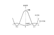
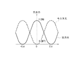
However, if the monitor light is extracted by such a method, the intensity of the monitor light becomes the same as the intensity of the output light (signal light) as shown in FIG. The strength of the monitor is too high, and the monitor PD may be broken.
Recently, there has been proposed an RZ optical modulator that generates a RZ (Return to Zero) signal by using a two-stage Mach-Zehnder type optical modulator in which modulation by a clock signal and modulation by a data signal are connected in series. Yes.
[0007]
In such an RZ optical modulator, for example, as shown in FIGS. 20A and 20B, the output of the Mach-Zehnder type
[0008]
However, in such a method, it is difficult to perform accurate bias control, and the control is complicated. The present invention has been devised in view of such a problem, and allows a wider range of selection of components that can be employed as a light detection unit, enables accurate and reliable detection of monitor light, and further provides a bias. An optical waveguide device capable of obtaining monitor light having an appropriate intensity for use in control, and Optical device The purpose is to provide.
[0009]
It is another object of the present invention to enable easy and accurate bias control.
[0010]
[Means for Solving the Problems]
For this reason, the optical waveguide device of the present invention according to
[0014]
DETAILED DESCRIPTION OF THE INVENTION
Hereinafter, embodiments of the present invention will be described with reference to the drawings.
(Description of the first embodiment)
First, an optical waveguide device according to a first embodiment of the present invention will be described with reference to FIGS.
[0015]
Hereinafter, an optical modulator configured by applying the optical waveguide device of the present invention will be described with reference to FIG.
This optical modulator is composed of lithium niobate (lithium niobate, LiNbO Three Mach-Zehnder type optical modulator (MZ type LN optical modulator) using LN). Such an optical modulator is provided in an optical transmitter, for example.
[0016]
That is, as shown in FIG. 1, the MZ type LN
[0017]
Here, a lithium niobate crystal is used as the
Where LiNbO Three Crystal or LiTaO 2 An MZ type LN
[0018]
Specifically, for example, LiNbO Three When a crystal is used for a substrate, a titanium film (Ti film) is patterned on the substrate according to a desired optical waveguide shape, and in such a patterned state, it is heated and diffused by heating at 1050 ° C. for 7 to 10 hours. Thus, an optical waveguide is formed.
In the present embodiment, as shown in FIG. 1, the
[0019]
Here, the 3
[0020]
As described above, the
Further, as shown in FIG. 1, the
[0021]
Then, by supplying a data signal from the data signal supply unit 7 to the
[0022]
In the present embodiment, as shown in FIG. 1, one end (output side end, termination) of the
[0023]
In particular, the effective refractive index of the linear
The
[0024]
By supplying a bias voltage (DC voltage) to the
Here, as will be described later, the bias control unit 8 performs feedback control for controlling the bias voltage based on the intensity of the monitor light, thereby compensating for fluctuations in the operating point voltage of the MZ type LN
[0025]
In the present embodiment, the Z-axis cut lithium
Thus, in this embodiment, since the
[0026]
For this reason, the present
In the present embodiment, each of the
[0027]
By the way, in the
On the other hand, in the
[0028]
As shown in FIG. 1, the
[0029]
By the way, as described above, when the 3
[0030]
Therefore, in the present embodiment, as shown in FIG. 1, an
[0031]
Hereinafter, a specific configuration example of the
(1) As shown in FIG. 2, the attenuating
Specifically, as shown in FIG. 2, an
[0032]
Thus, if the monitoring
Here, when the attenuating
[0033]
In particular, as shown in FIG. 2, when the guided light guided through the
(2) As shown in FIG. 4, the attenuating
[0034]
Specifically, as shown in FIG. 4, an
[0035]
As described above, if the monitoring
(3) As shown in FIG. 5, the attenuating
[0036]
Specifically, as shown in FIG. 5, an
[0037]
As described above, if the monitoring
(4) As shown in FIGS. 6 and 7, the attenuating
[0038]
Here, for example, as shown in FIG. 6, the
[0039]
In this way, if the
[0040]
Further, the
[0041]
In this way, if the
(5) The
[0042]
That is, for example, as shown in FIG. 8, a
[0043]
Thus, when the
Therefore, according to the
[0044]
Therefore, according to the present optical waveguide device (optical modulator), the monitor light can be detected accurately and reliably, the range of selection of the
In the above-described embodiment, the optical waveguide device according to the present invention is applied to the Mach-Zehnder type
[0045]
In the above-described embodiment, the case where the optical waveguide device according to the present invention is applied to an optical modulator has been described. However, the optical waveguide device is not limited to this, and the present invention may be applied to other optical switches, for example. It can be applied to an optical waveguide device.
In the above-described embodiment, a part of the output light output from the optical modulator is extracted as monitor light, and the intensity of this monitor light is detected to perform feedback voltage bias control. For example, the intensity of the detected monitor light may be used for feedback control of a voltage applied by a signal supply unit (including a power supply circuit and a drive circuit).
[0046]
Furthermore, in the above-described embodiment, the optical modulator is configured as including the
(Description of Second Embodiment)
Next, an optical waveguide device according to a second embodiment of the present invention will be described.
[0047]
Hereinafter, an RZ optical modulator configured by applying the optical waveguide device of the present invention [an optical modulator that generates a RZ (Return to Zero) signal by giving a clock signal and a data signal to input light (clock modulation type) The optical modulator)] will be described with reference to FIGS.
The RZ optical modulator according to the present embodiment is used as, for example, an optical transmitter in a long-distance optical transmission system.
[0048]
In the present embodiment, as shown in FIG. 11, the RZ
That is, as shown in FIG. 11, the RZ
[0049]
It is assumed that the first
[0050]
Here, lithium niobate crystal is used as the substrate. However, the substrate may be any substrate as long as it has an electro-optic effect. For example, lithium tantalate (LiTaO 2 Other ferroelectric crystals such as LT) crystals can also be used.
Where LiNbO Three Crystal or LiTaO 2 An RZ
[0051]
Specifically, for example, LiNbO Three When a crystal is used for a substrate, a titanium film (Ti film) is patterned on the substrate according to a desired optical waveguide shape, and in such a patterned state, it is heated and diffused by heating at 1050 ° C. for 7 to 10 hours. Thus, an optical waveguide is formed.
In the present embodiment, as shown in FIG. 11, the optical waveguide is divided into two parallel linear optical waveguides in which the input-side
[0052]
Further, as shown in FIG. 11, the intermediate
[0053]
Here, the 3
[0054]
As described above, the RZ
Further, as shown in FIG. 11, the
[0055]
Then, a clock signal is supplied from the clock
[0056]
In the present embodiment, one end (output side end, termination) of the
[0057]
In particular, the effective refractive index of the linear
Similarly, as shown in FIG. 11, the
[0058]
Then, an NRZ data signal is supplied from the NRZ data signal
[0059]
In the present embodiment, one end (output side end, termination) of the
[0060]
In particular, the effective refractive index of the linear
Further, as shown in FIG. 11, the
[0061]
A bias voltage (DC voltage) is applied to the first
Here, as will be described later, the first
[0062]
Similarly, as shown in FIG. 11, the
[0063]
A bias voltage (DC voltage) is applied to the second
Here, as will be described later, the second
[0064]
In the present embodiment, a Z-axis cut lithium
[0065]
Thus, in the present embodiment, the
[0066]
For this reason, the present RZ
In the present embodiment, each of the
[0067]
In the present embodiment, as shown in FIG. 11, a 3
[0068]
Here, two
As a result, input light from a light source (semiconductor laser) (not shown) is introduced into the first
[0069]
In the present embodiment, as shown in FIG. 11, the first monitor
[0070]
Further, as shown in FIG. 11, the
[0071]
On the other hand, a second monitor
[0072]
As shown in FIG. 11, the
[0073]
Thus, in this embodiment, a part of the light (signal light) modulated by the first
[0074]
The
[0075]
Thereby, feedback control of the bias voltage performed to compensate for fluctuations in the operating point voltage of the first
Therefore, according to the RZ
[0076]
In the second embodiment, each of the first
In the second embodiment, the input side of the second
[0077]
Further, in the second embodiment, 3
(Description of First Modification of Second Embodiment)
Next, an RZ optical modulator as an optical waveguide device according to a first modification of the second embodiment of the present invention will be described with reference to FIG.
[0078]
The RZ optical modulator according to the first modification has a configuration of a first monitor optical waveguide connected to a 3
That is, in the first modification, as shown in FIG. 12, the first monitoring
[0079]
Since other configurations are the same as those of the second embodiment described above, description thereof is omitted here.
As described above, according to the first modification, in addition to the effects of the configuration of the second embodiment described above, the
(Description of Second Modification of Second Embodiment)
Next, an RZ optical modulator as an optical waveguide device according to a second modification of the second embodiment of the present invention will be described with reference to FIG.
[0080]
The RZ optical modulator according to the second modification is different from the above-described second embodiment in the method of monitoring the light output from the second
That is, as shown in FIG. 13, in the RZ
[0081]
Since other configurations are the same as those of the second embodiment described above, description thereof is omitted here.
Thus, according to the second modified example, in addition to the effects of the configuration of the second embodiment described above, the tolerance of the arrangement position of the
(Description of the third modification of the second embodiment)
Next, an RZ optical modulator as an optical waveguide device according to a third modification of the second embodiment of the present invention will be described with reference to FIGS. 14 (A) and 14 (B). 14A is a schematic plan view, and FIG. 14B is a schematic cross-sectional view.
[0082]
The RZ optical modulator according to the third modification is different from the above-described second embodiment in the method of monitoring the light output from the first
[0083]
That is, as shown in FIGS. 14A and 14B, in the RZ
[0084]
14A and 14B, the output side of the second
[0085]
In particular, as shown in FIG. 14B, the radiated light emitted from the branch portion of the Y-branch
[0086]
On the other hand, as shown in FIG. 14B, the radiated light emitted from the branch portion of the Y branch
[0087]
As described above, the
[0088]
In the third modification, the configuration on the input side of the first
[0089]
Thus, according to the third modification, in addition to the effects of the configuration of the second embodiment described above, the tolerance of the arrangement position of the
(Explanation of a fourth modification of the second embodiment)
Next, an RZ optical modulator as an optical waveguide device according to a fourth modification of the second embodiment of the present invention will be described with reference to FIG.
[0090]
The RZ optical modulator according to the fourth modification is different in the configuration on the output side of the first
[0091]
On the other hand, as shown in FIG. 15, the Y-branch
Further, as shown in FIG. 15, the output side of the second
[0092]
On the other hand, as shown in FIG. 15, the output-side
In the fourth modification, the configuration on the input side of the first
[0093]
As described above, according to the fourth modification, the output light becomes weak at a ratio of 1: N. Therefore, by appropriately designing the branch ratio of the 1: N coupler, the monitor
(Description of Fifth Modification of Second Embodiment)
Next, an RZ optical modulator as an optical waveguide device according to a fifth modification of the second embodiment of the present invention will be described with reference to FIG.
[0094]
The RZ optical modulator according to the fifth modification is different in the configuration on the output side of the first
[0095]
That is, as shown in FIG. 16, in the RZ
[0096]
On the other hand, as shown in FIG. 16, the Y branch
Further, as shown in FIG. 16, the output side of the second
[0097]
On the other hand, a Mach-Zehnder
[0098]
Here, as shown in FIG. 16, the
[0099]
Further, the Y branch
[0100]
Based on the intensity of the monitor light detected by the
[0101]
In this manner, by applying a predetermined DC voltage to the
On the other hand, as shown in FIG. 16, the output side
[0102]
In the fifth modification, the configuration on the input side of the first
[0103]
As described above, according to the fifth modification, as in the case of the fourth modification described above, the output light becomes weak at a ratio of 1: N, and therefore the branch ratio of the 1: N coupler is appropriately designed. As a result, there is no need to devise the waveguide shape in order to attenuate the monitor light propagating through the branched monitor
[0104]
As shown in FIG. 17, the monitoring optical waveguide of the first embodiment is propagated to the monitoring
[0105]
In each of the above-described embodiments and modifications, there is one in which the monitor PD is attached to the end surface of the substrate when the monitor light is extracted through the monitor optical waveguide. However, the present invention is not limited to this. Depending on the intensity of the monitor light guided through the monitor optical waveguide, the monitor optical waveguide may be attached to a position (for example, a housing) separated from the end face of the substrate by a predetermined distance.
[Appendix]
(Supplementary note 1) a substrate having an electro-optic effect;
A plurality of Mach-Zehnder type or directional coupler type optical waveguides formed in series on the substrate;
A plurality of electrodes provided independently for each of the plurality of optical waveguides;
An optical waveguide device comprising: a plurality of light detection units that independently detect the intensity of light emitted from the plurality of optical waveguides.
[0106]
(Supplementary note 2) A plurality of waveguide couplers provided on the respective output sides of the plurality of optical waveguides;
A plurality of monitoring optical waveguides coupled to one port of the plurality of waveguide couplers;
The optical waveguide device according to
[0107]
(Supplementary Note 3) The waveguide coupler is a 3 dB coupler,
The optical waveguide device according to
(Supplementary Note 4) The waveguide coupler is a 1: N coupler,
The optical waveguide device according to
[0108]
(Supplementary Note 5) The optical waveguide device according to
(Appendix 6) One or more waveguide couplers provided on the output side of one of the plurality of optical waveguides;
One or more Y-branch optical waveguides provided on the output side of the other optical waveguides among the plurality of optical waveguides;
One or a plurality of monitoring optical waveguides connected to one port of the waveguide coupler,
One of the plurality of photodetectors detects the intensity of the monitor light guided through the corresponding monitor optical waveguide, and the other photodetector detects from the branch portion of the corresponding Y branch optical waveguide. The optical waveguide device according to
[0109]
(Appendix 7) The plurality of optical waveguides are Mach-Zehnder type optical waveguides each having a Y-branch optical waveguide on the output side,
The plurality of light detectors are arranged with their positions shifted in the thickness direction of the output side end face of the substrate so that the intensity of the radiated light emitted from the corresponding branch portion of the Y branch optical waveguide can be detected. 2. The optical waveguide device according to
[0110]
(Appendix 8) One of the plurality of monitoring optical waveguides is formed to extend to the side surface of the substrate,
[0111]
(Additional remark 9) The said board | substrate is comprised with lithium niobate, The optical waveguide device of any one of additional marks 1-8 characterized by the above-mentioned.
(Appendix 10) a substrate having an electro-optic effect;
First and second Mach-Zehnder type optical waveguides formed in series on the substrate;
A first signal electrode provided in the first Mach-Zehnder optical waveguide and supplied with a clock signal;
A second signal electrode provided in the second Mach-Zehnder optical waveguide and supplied with a data signal;
A first bias electrode provided in the first Mach-Zehnder type optical waveguide and applied with a bias voltage;
A second bias electrode provided in the second Mach-Zehnder optical waveguide and applied with a bias voltage;
A first monitor PD for detecting the intensity of light output from the first Mach-Zehnder type optical waveguide;
An optical modulator comprising: a second monitor PD for detecting the intensity of light output from the second Mach-Zehnder type optical waveguide.
[0112]
(Supplementary Note 11) A 3 dB coupler provided on the output side of the first Mach-Zehnder optical waveguide or the second Mach-Zehnder optical waveguide;
The monitoring light that guides the light output from the first Mach-Zehnder type optical waveguide or the second Mach-Zehnder type optical waveguide to the first monitor PD or the second monitor PD as light that is branched by the 3 dB coupler. A waveguide,
The optical modulator according to
[0113]
(Supplementary note 12) a substrate having an electro-optic effect;
An optical waveguide formed on the substrate;
An electrode provided in the optical waveguide;
A monitoring optical waveguide for guiding a part of the light output from the optical waveguide as monitoring light;
An attenuator provided in the optical waveguide for monitoring, for attenuating the monitor light;
An optical waveguide device comprising: a light detection unit that detects the intensity of the monitor light guided through the monitoring optical waveguide and attenuated by the attenuation unit.
[0114]
(Supplementary note 13) The optical waveguide is a Mach-Zehnder optical waveguide,
13. The optical waveguide device according to appendix 12, wherein a 3 dB coupler is provided on the output side of the Mach-Zehnder optical waveguide.
(Supplementary note 14) The optical waveguide device according to Supplementary note 12 or 13, wherein the attenuating portion is constituted by a curved waveguide having a small radius of curvature constituting the monitoring optical waveguide.
[0115]
(Supplementary note 15) The optical waveguide device according to Supplementary note 12 or 13, wherein the attenuating portion is constituted by two or more branch portions constituting the monitoring optical waveguide.
(Additional remark 16) The said attenuation | damping part is comprised by the 1: N coupler which comprises the said optical waveguide for a monitor, The optical waveguide device of Additional remark 12 or 13 characterized by the above-mentioned.
[0116]
(Additional remark 17) The said attenuation | damping part is comprised by the beam expansion part provided in the edge part vicinity of the said optical waveguide for a monitor, The optical waveguide device of any one of Additional remarks 12-16 characterized by the above-mentioned.
(Supplementary note 18) The optical waveguide device according to any one of supplementary notes 12 to 16, wherein a beam expanding part is provided in the vicinity of an end of the optical waveguide for monitoring.
[0117]
(Additional remark 19) The said beam expansion part is comprised by making the edge part of the said optical waveguide for monitoring into the position of predetermined distance from the end surface or side surface of the said board | substrate, The light guide of Additional remark 17 or 18 Waveguide device.
(Supplementary note 20) The optical waveguide device according to supplementary note 17 or 18, wherein the beam expanding section is configured by bifurcating an end portion of the monitoring optical waveguide.
[0118]
(Supplementary note 21) a substrate having an electro-optic effect;
A plurality of Mach-Zehnder type or directional coupler type optical waveguides formed in series on the substrate;
A plurality of electrodes provided independently for each of the plurality of optical waveguides;
A plurality of photodetectors for independently detecting the intensity of light emitted from the plurality of optical waveguides;
Based on the intensity of light detected by one of the plurality of light detection units, the bias voltage applied to the electrode provided in the optical waveguide corresponding to the one light detection unit is controlled. An optical waveguide device, comprising: a bias control unit that performs the operation.
[0119]
【The invention's effect】
As detailed above, the optical waveguide device of the present invention and Optical device Since the monitor light is extracted through the monitor optical waveguide, the monitor light can be detected accurately and reliably, Monitor part There are advantages in that the range of selection of components that can be used as the sensor is widened, and that monitor light having an appropriate intensity for use in bias control can be obtained.
[0120]
The optical waveguide device of the present invention and Optical device According to multiple Mach-Zehnder types Monitor unit provided for the interferometer Therefore, since the monitor light is detected independently and the bias control is performed based on the detected monitor light, there is an advantage that the bias control can be easily and accurately performed.
[Brief description of the drawings]
FIG. 1 is a schematic diagram showing an overall configuration of an optical modulator as an optical waveguide device according to a first embodiment of the present invention.
FIG. 2 is an enlarged view schematically showing a configuration example of an attenuation unit provided in the optical modulator as the optical waveguide device according to the first embodiment of the present invention.
FIG. 3 is an enlarged view schematically showing another configuration example of the attenuation section provided in the optical modulator as the optical waveguide device according to the first embodiment of the present invention.
FIG. 4 is an enlarged view schematically showing another configuration example of the attenuating unit provided in the optical modulator as the optical waveguide device according to the first embodiment of the present invention.
FIG. 5 is an enlarged view schematically showing another configuration example of the attenuating unit provided in the optical modulator as the optical waveguide device according to the first embodiment of the present invention.
6 is an enlarged view schematically showing another configuration example of the attenuating unit provided in the optical modulator as the optical waveguide device according to the first embodiment of the present invention. FIG.
FIG. 7 is an enlarged view schematically showing another configuration example of the attenuation section provided in the optical modulator as the optical waveguide device according to the first embodiment of the present invention.
FIG. 8 is an enlarged view schematically showing another configuration example of the attenuation section provided in the optical modulator as the optical waveguide device according to the first embodiment of the present invention.
FIG. 9 is an enlarged view schematically showing another configuration example of the attenuating unit provided in the optical modulator as the optical waveguide device according to the first embodiment of the present invention.
FIG. 10 is a diagram showing optical outputs of signal light and monitor light in the optical modulator as the optical waveguide device according to the first embodiment of the present invention.
FIG. 11 is a schematic diagram showing an overall configuration of an RZ optical modulator as an optical waveguide device according to a second embodiment of the present invention.
FIG. 12 is a schematic diagram showing an overall configuration of an RZ optical modulator as an optical waveguide device according to a first modification of the second embodiment of the present invention.
FIG. 13 is a schematic diagram showing an overall configuration of an RZ optical modulator as an optical waveguide device according to a second modification of the second embodiment of the present invention.
FIG. 14 is a schematic diagram showing an overall configuration of an RZ optical modulator as an optical waveguide device according to a third modification of the second embodiment of the present invention.
FIG. 15 is a schematic diagram showing an overall configuration of an RZ optical modulator as an optical waveguide device according to a fourth modification of the second embodiment of the present invention.
FIG. 16 is a schematic diagram showing an overall configuration of an RZ optical modulator as an optical waveguide device according to a fifth modification of the second embodiment of the present invention.
FIG. 17 is a schematic diagram showing an overall configuration of an RZ optical modulator as an optical waveguide device according to another modification of the second embodiment of the present invention.
FIG. 18 is a diagram for explaining a method of taking out monitor light used for bias control using a monitor optical waveguide;
FIG. 19 is a diagram for explaining a problem when monitoring light is extracted using a monitoring optical waveguide, and is a diagram illustrating optical outputs of signal light and monitoring light;
FIG. 20 is a diagram for explaining bias control in the RZ optical modulator.
[Explanation of symbols]
1 MZ type LN optical modulator
2 Substrate
2A end face
3A optical waveguide (MZ type optical waveguide)
3 Optical waveguide
3a Input side optical waveguide
3b Y-branch optical waveguide
3c, 3d linear optical waveguide
3e Output side optical waveguide
3f Monitor optical waveguide
3g linear optical waveguide
3h 2 branch optical waveguide
4 Main electrode
4a Signal electrode
4b Ground electrode
5 Bias electrode
5a electrode
5b Ground electrode
6 3dB coupler (waveguide type coupler)
7 Data signal supply unit (signal supply unit)
8 Bias controller
9 Attenuator
9a Curved waveguide
9b Branch optical waveguide (multiple branch optical waveguide, multi-branch optical waveguide)
9c 1: N coupler
9d Beam expansion part
10 Monitor PD (Photodetector, Monitor PD for bias control, Photodetector)
20 RZ optical modulator
21, 41 Mach-Zehnder type optical modulator (MZ type LN optical modulator)
22 Substrate
23 First optical waveguide
23b, 23c linear optical waveguide
23d Optical waveguide for monitoring
24 Second optical waveguide
24a Y branch optical waveguide (branch optical waveguide)
24b, 24c linear optical waveguide
24d optical waveguide for monitoring
25 First electrode (main electrode)
25a Signal electrode
25b Ground electrode
26 First bias electrode
26a electrode
26b Ground electrode
27 Second electrode (main electrode)
27a Signal electrode
27b Ground electrode
28 Second bias electrode
28a electrode
28b Ground electrode
29a 3dB coupler (waveguide type coupler)
29b 3dB coupler (waveguide coupler)
29c 3dB coupler (waveguide coupler)
30 Input side optical waveguide
31 Intermediate optical waveguide
32 Output-side optical waveguide
33 Clock signal supply unit (signal supply unit)
34 NRZ data signal supply unit (signal supply unit)
35 First bias controller
36 Second bias control unit
37 First monitor PD (light detection unit)
38 Second monitor PD (light detection unit)
60, 70, 80, 90 RZ optical modulator
61, 71, 72, 73, 81, 83, 91, 93 Y-branch optical waveguide
82, 84, 92, 94 1: N coupler (eg, 1:10 coupler, waveguide type optical coupler)
95 Variable attenuator
96 Optical waveguide
96a, 96d Y branch optical waveguide
96b, 96c linear optical waveguide
97 electrodes
98 Bias electrode
99 1: N coupler (eg, 1:10 coupler, waveguide type optical coupler)
100 Third monitor optical waveguide
101 Third monitor PD (light detection unit)
102 Y-branch optical waveguide
Claims (1)
該基板上に前記長辺方向に並んで形成され、光学的に結合された第1、第2のマッハツェンダ型干渉計と、
前記基板の第1の短辺側に設けられた前記第1のマッハツェンダ型干渉計からの出力光の一部の放射である第1放射光に対応した位置に設けられた第1モニタ部と、
前記基板の第2の短辺側に設けられた前記第2のマッハツェンダ型干渉計からの出力光の一部の放射である第2放射光に対応した位置に設けられた第2モニタ部と、を備え、
前記基板は、前記第1モニタ部、前記第2モニタ部で検出可能な該第1放射光、該第2放射光がともに、前記第2の短辺を含む側面内から出力されるように、前記長辺の長さ、前記側面の前記第2の短辺以外の辺の長さが設定され、
前記第1モニタ部と前記第2モニタ部を前記第2の短辺を含む側面側に設け、
前記第1モニタ部と前記第2モニタ部は、前記基板の厚み方向にずらして配置された、
ことを特徴とする光導波路デバイス。 A substrate having a long side and a short side having an electro-optic effect;
First and second Mach-Zehnder interferometers formed side by side on the substrate in the long side direction and optically coupled;
A first monitor unit provided at a position corresponding to the first radiated light that is a part of the output light from the first Mach-Zehnder interferometer provided on the first short side of the substrate;
A second monitor unit provided at a position corresponding to the second radiated light that is a part of the output light from the second Mach-Zehnder interferometer provided on the second short side of the substrate; With
The substrate is configured such that both the first radiated light and the second radiated light that can be detected by the first monitor unit and the second monitor unit are output from the side surface including the second short side. The length of the long side, the length of the side other than the second short side of the side surface is set,
The first monitor unit and the second monitor unit are provided on a side surface including the second short side,
The first monitor unit and the second monitor unit are arranged to be shifted in the thickness direction of the substrate,
An optical waveguide device characterized by the above .
Priority Applications (3)
| Application Number | Priority Date | Filing Date | Title |
|---|---|---|---|
| JP2002031304A JP3974792B2 (en) | 2002-02-07 | 2002-02-07 | Optical waveguide device and optical device |
| US10/345,938 US7340114B2 (en) | 2002-02-07 | 2003-01-17 | Optical waveguide device and optical modulator |
| EP03001352A EP1335242A1 (en) | 2002-02-07 | 2003-01-24 | Optical waveguide device and optical modulator |
Applications Claiming Priority (1)
| Application Number | Priority Date | Filing Date | Title |
|---|---|---|---|
| JP2002031304A JP3974792B2 (en) | 2002-02-07 | 2002-02-07 | Optical waveguide device and optical device |
Related Child Applications (1)
| Application Number | Title | Priority Date | Filing Date |
|---|---|---|---|
| JP2006319552A Division JP4719135B2 (en) | 2006-11-28 | 2006-11-28 | Optical waveguide device and optical device |
Publications (2)
| Publication Number | Publication Date |
|---|---|
| JP2003233047A JP2003233047A (en) | 2003-08-22 |
| JP3974792B2 true JP3974792B2 (en) | 2007-09-12 |
Family
ID=27606520
Family Applications (1)
| Application Number | Title | Priority Date | Filing Date |
|---|---|---|---|
| JP2002031304A Expired - Fee Related JP3974792B2 (en) | 2002-02-07 | 2002-02-07 | Optical waveguide device and optical device |
Country Status (3)
| Country | Link |
|---|---|
| US (1) | US7340114B2 (en) |
| EP (1) | EP1335242A1 (en) |
| JP (1) | JP3974792B2 (en) |
Cited By (1)
| Publication number | Priority date | Publication date | Assignee | Title |
|---|---|---|---|---|
| US9069193B2 (en) | 2011-06-01 | 2015-06-30 | Nec Corporation | Optical waveguide device, optical interferometer, and method for producing optical waveguide device |
Families Citing this family (47)
| Publication number | Priority date | Publication date | Assignee | Title |
|---|---|---|---|---|
| US7200289B2 (en) * | 2000-03-15 | 2007-04-03 | Sumitomo Osaka Cement Co., Ltd. | Optical waveguide modulator with output light monitor |
| JP4083657B2 (en) * | 2003-03-28 | 2008-04-30 | 住友大阪セメント株式会社 | Bias control method and apparatus for optical modulator |
| US7184643B2 (en) * | 2003-04-29 | 2007-02-27 | Xponent Photonics Inc | Multiple-core planar optical waveguides and methods of fabrication and use thereof |
| US7425696B2 (en) * | 2004-02-19 | 2008-09-16 | National Institute Of Information And Communications Technology Incorporated Administrative Agency | Photoelectric oscillator |
| JP4524482B2 (en) * | 2004-03-24 | 2010-08-18 | 独立行政法人情報通信研究機構 | Optical SSB modulator |
| KR100545778B1 (en) * | 2004-05-24 | 2006-01-24 | 광주과학기술원 | Apparatus and method for equalizing pulse amplitude in rational aberration harmonic mode-locked semiconductor fiber laser |
| EP1653273A4 (en) * | 2004-06-15 | 2007-12-19 | Anritsu Corp | Optical modulator with monitor photodetector |
| JP2006047956A (en) * | 2004-06-29 | 2006-02-16 | Anritsu Corp | Waveguide type optical device |
| JP4278586B2 (en) | 2004-08-05 | 2009-06-17 | 富士通株式会社 | Light modulator |
| GB2417333B (en) | 2004-08-13 | 2008-07-16 | Bookham Technology Plc | Automatic bias controller for an optical modulator |
| US7161726B2 (en) * | 2004-11-05 | 2007-01-09 | Lumera Corporation | Linear optical modulators and method of linear optical modulation |
| US7398023B2 (en) * | 2004-12-15 | 2008-07-08 | Tyco Telecommunications (Us) Inc. | Method and apparatus for bias and alignment control in an optical signal transmitter |
| EP1868025A4 (en) * | 2005-02-22 | 2010-05-12 | Ngk Insulators Ltd | Optical modulator |
| JP4874685B2 (en) * | 2005-03-25 | 2012-02-15 | 住友大阪セメント株式会社 | Light modulator |
| JP4234117B2 (en) * | 2005-07-07 | 2009-03-04 | アンリツ株式会社 | Light modulator |
| US7466877B2 (en) * | 2005-09-23 | 2008-12-16 | Fujitsu Limited | Monitoring modulation alignment variation using photon absorption |
| JP2007093717A (en) | 2005-09-27 | 2007-04-12 | Oki Electric Ind Co Ltd | Optical modulator and control method thereof |
| US7522784B2 (en) * | 2006-02-27 | 2009-04-21 | Jds Uniphase Corporation | Asymmetric directional coupler having a reduced drive voltage |
| JP5070853B2 (en) * | 2006-07-19 | 2012-11-14 | 富士通オプティカルコンポーネンツ株式会社 | Optical device |
| JP4756011B2 (en) | 2007-06-22 | 2011-08-24 | 富士通株式会社 | Optical device |
| JP4946833B2 (en) * | 2007-11-30 | 2012-06-06 | 富士通オプティカルコンポーネンツ株式会社 | Light modulator |
| JP5045416B2 (en) * | 2007-12-17 | 2012-10-10 | 富士通株式会社 | Optical waveguide device and optical device using the same |
| US20090169149A1 (en) * | 2007-12-27 | 2009-07-02 | Bruce Andrew Block | Stabilized ring resonator modulator |
| JP5333236B2 (en) | 2008-02-01 | 2013-11-06 | 日本電気株式会社 | Wavelength tunable light source, optical module, and method for controlling wavelength tunable light source |
| JP5270998B2 (en) * | 2008-07-30 | 2013-08-21 | Nttエレクトロニクス株式会社 | Planar optical waveguide circuit |
| JP5239610B2 (en) * | 2008-08-13 | 2013-07-17 | 富士通株式会社 | Mach-Zehnder optical modulator |
| US20120087653A1 (en) * | 2009-07-01 | 2012-04-12 | Mitsubishi Electric Corporation | Optical transmission apparatus and optical transmission method |
| JP5451872B2 (en) * | 2010-03-19 | 2014-03-26 | 日本電信電話株式会社 | Light modulator |
| JP5193245B2 (en) * | 2010-03-30 | 2013-05-08 | 日本電信電話株式会社 | Light modulator |
| JP5402802B2 (en) * | 2010-04-09 | 2014-01-29 | 日本電気株式会社 | Optical waveguide circuit and method of manufacturing optical waveguide circuit |
| CN103392146B (en) * | 2011-02-23 | 2015-05-06 | 住友大阪水泥股份有限公司 | Light modulator |
| CN103858035A (en) | 2011-10-28 | 2014-06-11 | Hoya美国公司 | Optical waveguide splitter on a waveguide substrate for attenuating a light source |
| EP3079007B1 (en) * | 2012-01-12 | 2019-01-09 | Fraunhofer-Gesellschaft zur Förderung der angewandten Forschung e.V. | Mach-zehnder modulator arrangement and method for operating a mach-zehnder modulator arrangement |
| JP2014194478A (en) * | 2013-03-28 | 2014-10-09 | Fujitsu Optical Components Ltd | Optical device and transmitter |
| JP6232751B2 (en) * | 2013-05-31 | 2017-11-22 | 富士通オプティカルコンポーネンツ株式会社 | Light modulator |
| JP5861724B2 (en) * | 2014-01-31 | 2016-02-16 | 住友大阪セメント株式会社 | Optical device |
| KR102559579B1 (en) * | 2015-09-03 | 2023-07-25 | 삼성전자주식회사 | Optical modulator and data processing system using the same |
| US9715066B2 (en) * | 2015-12-24 | 2017-07-25 | Intel Corporation | Double-sided orthogonal grating optical coupler |
| JP6424855B2 (en) * | 2016-03-25 | 2018-11-21 | 住友大阪セメント株式会社 | Light modulator |
| JP2017173663A (en) * | 2016-03-25 | 2017-09-28 | 住友大阪セメント株式会社 | Light modulator |
| JP2017211504A (en) | 2016-05-26 | 2017-11-30 | 住友大阪セメント株式会社 | Optical modulator |
| US11057114B2 (en) * | 2016-08-04 | 2021-07-06 | Acacia Communications, Inc. | Optical loopback circuits for transceivers and related methods |
| JP2018180513A (en) * | 2017-04-17 | 2018-11-15 | 日本電信電話株式会社 | Monitoring light source |
| JP6823571B2 (en) * | 2017-09-05 | 2021-02-03 | 日本電信電話株式会社 | Optical circuit |
| JP7047469B2 (en) * | 2018-03-05 | 2022-04-05 | 住友大阪セメント株式会社 | Optical modulator |
| US10935738B1 (en) | 2019-08-08 | 2021-03-02 | Stmicroelectronics S.R.L. | Architecture of an integrated optics device |
| US20250216187A1 (en) * | 2023-12-28 | 2025-07-03 | Intel Corporation | Tunable cascaded mach-zehnder interferometer structures |
Family Cites Families (53)
| Publication number | Priority date | Publication date | Assignee | Title |
|---|---|---|---|---|
| FR2424674A1 (en) * | 1978-04-25 | 1979-11-23 | Thomson Csf | INTEGRATED OPTICAL DEMULTIPLEXING CIRCUIT |
| FR2457505A1 (en) * | 1979-05-23 | 1980-12-19 | Thomson Csf | LIGHT INTENSITY MODULATOR WITH INTEGRATED OPTICAL DIGITAL CONTROL AND ANALOG DIGITAL CONVERTER COMPRISING SUCH A MODULATOR |
| US4618210A (en) * | 1982-06-09 | 1986-10-21 | Nec Corporation | Optical switch of switched directional coupler type |
| JPS6180109A (en) * | 1984-09-26 | 1986-04-23 | Nippon Telegr & Teleph Corp <Ntt> | Optical multiplexer and demultiplexer |
| GB2171514B (en) * | 1985-02-23 | 1988-03-09 | Stc Plc | Magnetic gradient detector and method |
| US4763973A (en) * | 1985-02-27 | 1988-08-16 | Omron Tateisi Electronics Co. | Waveguide-type optical sensor |
| US4904940A (en) * | 1988-03-18 | 1990-02-27 | The Boeing Company | Fiber-optic multicomponent magnetic field gradiometer for first, second and higher order derivatives |
| US4989979A (en) * | 1989-01-17 | 1991-02-05 | Board Of Regents, The University Of Texas System | Optical fiber sensors with full common-mode compensation and measurand sensitivity enhancement |
| US5031235A (en) * | 1989-10-27 | 1991-07-09 | Hoechst Celanese Corp. | Cable system incorporating highly linear optical modulator |
| JP2738078B2 (en) * | 1989-11-01 | 1998-04-08 | 富士通株式会社 | Light modulator |
| US5051578A (en) * | 1989-11-15 | 1991-09-24 | Slemon Charles S | Self calibrating fiber optic sensor system with optimized throughput |
| FR2658315A1 (en) * | 1990-02-14 | 1991-08-16 | France Etat | POLARIZATION SEPARATOR FOR GUIDED LIGHT. |
| US5040865A (en) * | 1990-04-20 | 1991-08-20 | Hughes Aircraft Company | Frequency multiplying electro-optic modulator configuration and method |
| DE4021293A1 (en) * | 1990-07-04 | 1992-01-16 | Deutsche Forsch Luft Raumfahrt | BISTABLE OPTICAL SWITCH |
| JPH0534650A (en) * | 1991-05-10 | 1993-02-12 | Fujitsu Ltd | Branch interferometric optical modulator with monitor |
| US5148503A (en) * | 1991-05-29 | 1992-09-15 | Crystal Technology, Inc | Apparatus and method for linearized cascade coupled integrated optical modulator |
| JP3199402B2 (en) * | 1991-08-28 | 2001-08-20 | 富士通株式会社 | Mach-Zehnder optical waveguide device |
| US5168534A (en) * | 1991-12-09 | 1992-12-01 | United Technologies Corporation | Cascaded optic modulator arrangement |
| US5404412A (en) * | 1991-12-27 | 1995-04-04 | Fujitsu Limited | Optical waveguide device |
| US5278923A (en) * | 1992-09-02 | 1994-01-11 | Harmonic Lightwaves, Inc. | Cascaded optical modulation system with high linearity |
| US5323406A (en) * | 1992-11-02 | 1994-06-21 | Yee Ting K | Photonic mixer for photonically multiplying two electrical signals in two optically interconnected interferometric modulators operated at modulation outside the linear range |
| DE9217040U1 (en) * | 1992-12-15 | 1994-04-14 | Robert Bosch Gmbh, 70469 Stuttgart | Packaging box for elongated objects |
| US5617500A (en) * | 1994-05-20 | 1997-04-01 | Nikon Corporation | System for detecting an optical information and scanning microscope system |
| US5644664A (en) * | 1994-06-10 | 1997-07-01 | The United States Of America As Represented By The Secretary Of The Navy | Fiber optic digital transmission system |
| US5994891A (en) * | 1994-09-26 | 1999-11-30 | The Boeing Company | Electrically small, wideband, high dynamic range antenna having a serial array of optical modulators |
| JPH08146366A (en) * | 1994-11-25 | 1996-06-07 | Hitachi Ltd | Light modulator |
| DE19503929A1 (en) * | 1995-02-07 | 1996-08-08 | Ldt Gmbh & Co | Color imaging systems |
| US5723856A (en) * | 1995-08-01 | 1998-03-03 | California Institute Of Technology | Opto-electronic oscillator having a positive feedback with an open loop gain greater than one |
| JP2765529B2 (en) * | 1995-09-29 | 1998-06-18 | 日本電気株式会社 | Waveguide type optical device |
| US5671302A (en) * | 1996-03-29 | 1997-09-23 | Crystal Technology, Inc. | Linearized optic modulator with segmented electrodes |
| US5611005A (en) * | 1996-04-26 | 1997-03-11 | Lucent Technologies, Inc. | High-speed polarization scrambler with adjustable chirp |
| JP3717605B2 (en) * | 1996-09-05 | 2005-11-16 | 富士通株式会社 | Optical modulator module |
| JP3724894B2 (en) | 1996-10-24 | 2005-12-07 | 富士通株式会社 | Optical transmitter |
| JP3820009B2 (en) * | 1997-09-26 | 2006-09-13 | 富士通株式会社 | Optical modulator and optical modulation method |
| US6335524B1 (en) * | 1997-10-22 | 2002-01-01 | Blue Road Research | High speed demodulation systems for fiber optic grating sensors |
| JP3337629B2 (en) | 1997-10-30 | 2002-10-21 | エヌティティエレクトロニクス株式会社 | Waveguide type optical variable attenuator |
| US6016371A (en) * | 1997-12-19 | 2000-01-18 | Trw Inc. | Optical RF signal processing |
| US6166756A (en) * | 1998-06-02 | 2000-12-26 | Science Applications International Corporation | Multiple channel data writing device |
| US6522797B1 (en) * | 1998-09-01 | 2003-02-18 | Input/Output, Inc. | Seismic optical acoustic recursive sensor system |
| US6201237B1 (en) * | 1998-12-18 | 2001-03-13 | Corning Incorporated | Fiber optic sensor |
| US6445477B1 (en) * | 1999-02-11 | 2002-09-03 | Lucent Technologies | Self-monitored light source for stable wavelength optical communications |
| US6332055B1 (en) * | 1999-03-02 | 2001-12-18 | Sumitomo Electric Industries, Ltd. | Optical attenuator, plane waveguide type optical circuit having the same and optical attenuation system having the same |
| JP2001209018A (en) * | 2000-01-26 | 2001-08-03 | Nec Corp | Optical modulator with monitor |
| JP3696024B2 (en) | 2000-02-02 | 2005-09-14 | 住友大阪セメント株式会社 | Optical waveguide modulator with output light monitor |
| JP4519248B2 (en) * | 2000-03-14 | 2010-08-04 | 富士通株式会社 | Optical device with optical waveguide |
| JP2001296506A (en) | 2000-04-13 | 2001-10-26 | Nec Corp | Rz optical transmitter |
| JP2002023123A (en) | 2000-07-11 | 2002-01-23 | Fujitsu Ltd | Optical circuit with optical waveguide for guiding non-primary light |
| US20030016937A1 (en) * | 2001-02-23 | 2003-01-23 | Caracci Stephen J. | Variable optic attenuator by waveguide bend loss |
| US6822743B2 (en) * | 2001-03-07 | 2004-11-23 | Paul Trinh | Integrated-optic channel monitoring |
| EP1191321B1 (en) * | 2001-06-07 | 2002-12-11 | Agilent Technologies, Inc. (a Delaware corporation) | Determination of properties of an optical device |
| EP1280289B1 (en) * | 2001-07-27 | 2010-11-10 | Nippon Telegraph And Telephone Corporation | Polarization mode dispersion compensating device using optical XOR circuit |
| ATE272228T1 (en) | 2002-01-08 | 2004-08-15 | Cit Alcatel | VARIABLE OPTICAL DELAY LINE AND USE OF THE VARIABLE OPTICAL DELAY LINE |
| JP2003329986A (en) * | 2002-05-15 | 2003-11-19 | Fujitsu Ltd | Optical modulator and optical waveguide device |
-
2002
- 2002-02-07 JP JP2002031304A patent/JP3974792B2/en not_active Expired - Fee Related
-
2003
- 2003-01-17 US US10/345,938 patent/US7340114B2/en not_active Expired - Lifetime
- 2003-01-24 EP EP03001352A patent/EP1335242A1/en not_active Withdrawn
Cited By (1)
| Publication number | Priority date | Publication date | Assignee | Title |
|---|---|---|---|---|
| US9069193B2 (en) | 2011-06-01 | 2015-06-30 | Nec Corporation | Optical waveguide device, optical interferometer, and method for producing optical waveguide device |
Also Published As
| Publication number | Publication date |
|---|---|
| US20030147591A1 (en) | 2003-08-07 |
| US7340114B2 (en) | 2008-03-04 |
| EP1335242A1 (en) | 2003-08-13 |
| JP2003233047A (en) | 2003-08-22 |
Similar Documents
| Publication | Publication Date | Title |
|---|---|---|
| JP3974792B2 (en) | Optical waveguide device and optical device | |
| US5361157A (en) | Bidirectional light transmission system and optical device therefor | |
| JP4241622B2 (en) | Light modulator | |
| JP3800594B2 (en) | Light modulator | |
| JP5092573B2 (en) | Optical waveguide device | |
| US6876782B2 (en) | Integrated type optical waveguide device | |
| JP4842987B2 (en) | Optical device | |
| JP2003329986A (en) | Optical modulator and optical waveguide device | |
| JP5660095B2 (en) | Light modulator | |
| WO2007149721A1 (en) | Tunable optical dispersion compensators | |
| US7386198B2 (en) | Optical waveguide device | |
| JP4308712B2 (en) | Optical device | |
| WO2022210855A1 (en) | Optical waveguide element, and optical modulation device and optical transmission device which use same | |
| JP2009145781A (en) | Optical waveguide device and optical device using the same | |
| US20090269017A1 (en) | Optical waveguide device | |
| JP4719135B2 (en) | Optical waveguide device and optical device | |
| JP4025799B2 (en) | Optical modulator with monitor photodetector | |
| US7373025B2 (en) | Waveguide-type optical device | |
| JP4917977B2 (en) | Optical modulator with monitor photodetector | |
| US12455488B2 (en) | Optical coupling device with adjustable coupling coefficient | |
| JP4701428B2 (en) | Driving circuit for traveling wave electrode, optical modulation system using the same, optical information communication system, and driving method for traveling wave electrode | |
| JP2898066B2 (en) | Optical device | |
| JPH04333829A (en) | Waveguide type optical device | |
| JPS6294832A (en) | Optical heterodyne detecting device |
Legal Events
| Date | Code | Title | Description |
|---|---|---|---|
| A621 | Written request for application examination |
Free format text: JAPANESE INTERMEDIATE CODE: A621 Effective date: 20040903 |
|
| A977 | Report on retrieval |
Free format text: JAPANESE INTERMEDIATE CODE: A971007 Effective date: 20060130 |
|
| A131 | Notification of reasons for refusal |
Free format text: JAPANESE INTERMEDIATE CODE: A131 Effective date: 20060704 |
|
| A521 | Written amendment |
Free format text: JAPANESE INTERMEDIATE CODE: A523 Effective date: 20060831 |
|
| A131 | Notification of reasons for refusal |
Free format text: JAPANESE INTERMEDIATE CODE: A131 Effective date: 20061003 |
|
| A521 | Written amendment |
Free format text: JAPANESE INTERMEDIATE CODE: A523 Effective date: 20061128 |
|
| A02 | Decision of refusal |
Free format text: JAPANESE INTERMEDIATE CODE: A02 Effective date: 20070213 |
|
| A521 | Written amendment |
Free format text: JAPANESE INTERMEDIATE CODE: A523 Effective date: 20070306 |
|
| A911 | Transfer to examiner for re-examination before appeal (zenchi) |
Free format text: JAPANESE INTERMEDIATE CODE: A911 Effective date: 20070411 |
|
| TRDD | Decision of grant or rejection written | ||
| A01 | Written decision to grant a patent or to grant a registration (utility model) |
Free format text: JAPANESE INTERMEDIATE CODE: A01 Effective date: 20070522 |
|
| A61 | First payment of annual fees (during grant procedure) |
Free format text: JAPANESE INTERMEDIATE CODE: A61 Effective date: 20070615 |
|
| R150 | Certificate of patent or registration of utility model |
Free format text: JAPANESE INTERMEDIATE CODE: R150 Ref document number: 3974792 Country of ref document: JP Free format text: JAPANESE INTERMEDIATE CODE: R150 |
|
| FPAY | Renewal fee payment (event date is renewal date of database) |
Free format text: PAYMENT UNTIL: 20100622 Year of fee payment: 3 |
|
| FPAY | Renewal fee payment (event date is renewal date of database) |
Free format text: PAYMENT UNTIL: 20100622 Year of fee payment: 3 |
|
| S111 | Request for change of ownership or part of ownership |
Free format text: JAPANESE INTERMEDIATE CODE: R313111 |
|
| FPAY | Renewal fee payment (event date is renewal date of database) |
Free format text: PAYMENT UNTIL: 20100622 Year of fee payment: 3 |
|
| R350 | Written notification of registration of transfer |
Free format text: JAPANESE INTERMEDIATE CODE: R350 |
|
| FPAY | Renewal fee payment (event date is renewal date of database) |
Free format text: PAYMENT UNTIL: 20110622 Year of fee payment: 4 |
|
| R250 | Receipt of annual fees |
Free format text: JAPANESE INTERMEDIATE CODE: R250 |
|
| FPAY | Renewal fee payment (event date is renewal date of database) |
Free format text: PAYMENT UNTIL: 20120622 Year of fee payment: 5 |
|
| FPAY | Renewal fee payment (event date is renewal date of database) |
Free format text: PAYMENT UNTIL: 20120622 Year of fee payment: 5 |
|
| FPAY | Renewal fee payment (event date is renewal date of database) |
Free format text: PAYMENT UNTIL: 20130622 Year of fee payment: 6 |
|
| FPAY | Renewal fee payment (event date is renewal date of database) |
Free format text: PAYMENT UNTIL: 20140622 Year of fee payment: 7 |
|
| LAPS | Cancellation because of no payment of annual fees |

