JP3973623B2 - Object tracking method and object tracking device - Google Patents
Object tracking method and object tracking device Download PDFInfo
- Publication number
- JP3973623B2 JP3973623B2 JP2003422254A JP2003422254A JP3973623B2 JP 3973623 B2 JP3973623 B2 JP 3973623B2 JP 2003422254 A JP2003422254 A JP 2003422254A JP 2003422254 A JP2003422254 A JP 2003422254A JP 3973623 B2 JP3973623 B2 JP 3973623B2
- Authority
- JP
- Japan
- Prior art keywords
- image
- detected
- template
- moving object
- difference
- Prior art date
- Legal status (The legal status is an assumption and is not a legal conclusion. Google has not performed a legal analysis and makes no representation as to the accuracy of the status listed.)
- Expired - Fee Related
Links
Images


Description
本発明は、撮像装置を用いた物体追尾システムに係り、特に追尾対象領域内の物体を画像信号の処理により自動的に検出し、当該撮像装置を搭載するカメラ雲台を制御するようにして物体を追尾するようにした物体追尾方法及び物体追尾装置に関する。 The present invention relates to an object tracking system using an imaging device, and in particular, automatically detects an object in a tracking target area by processing an image signal and controls a camera platform on which the imaging device is mounted. The present invention relates to an object tracking method and an object tracking device.
TVカメラ(テレビジョンカメラ)などの撮像装置(以下、カメラと称する)
を用いた遠隔モニタ方式の監視システム等の物体追尾システムは、従来から広く用いられているが、その多くは、監視員がモニタに表示される画像を見ながら監視を行なう、いわゆる有人監視方式の監視システムである。しかし、この有人監視方式の監視システムでは、監視員が常時モニタに表示される映像を見ていて、監視対象領域内に入り込んでくる人間や自動車などの侵入物体(検出物体)をリアルタイムで識別する必要があり、監視員に大きな負担がかかる。
Imaging devices (hereinafter referred to as cameras) such as TV cameras (television cameras)
An object tracking system such as a remote monitoring type monitoring system using a conventional method has been widely used, but most of them are so-called manned monitoring type methods in which an observer observes an image while viewing an image displayed on the monitor. It is a monitoring system. However, in this manned monitoring system monitoring system, an observer constantly watches the video displayed on the monitor and identifies intruding objects (detected objects) such as humans and automobiles entering the monitored area in real time. This is necessary and puts a heavy burden on the observer.
人間の集中力には限りがあるため、有人監視方式の監視システムでは、侵入してくる物体の見逃しの発生を無視できず、監視の信頼性の面で問題がある。また、カメラが撮像した画像(カメラ映像)内にある侵入物体を見つけた場合に、侵入物体をカメラの視野(即ち、撮像視野)範囲内に捉えておくために、カメラを搭載するカメラ雲台(電動旋回台)を操作することが必要になる。しかし、近年の監視カメラの爆発的な普及もあって、監視員1人でそれぞれ、数多くのカメラ映像を複数のモニタを使って監視することも多くなっており、複数のカメラで同時に侵入物体を捉えた場合等、同時に複数のカメラ各々のカメラ雲台を同時に操作することは困難である。この場合にも侵入物体の見逃しが発生する可能性がある。 Due to the limited human concentration, the manned monitoring system cannot accurately ignore the intruding object, and there is a problem in monitoring reliability. In addition, when an intruding object is found in an image (camera image) captured by the camera, the camera platform on which the camera is mounted is used in order to keep the intruding object within the field of view of the camera (that is, the imaging field of view). It is necessary to operate the (electric turntable). However, due to the explosive spread of surveillance cameras in recent years, it is often the case that one surveillance person monitors a large number of camera images using multiple monitors. It is difficult to simultaneously operate the camera platform of each of a plurality of cameras at the same time. Even in this case, there is a possibility that an intruding object may be missed.
そこで、このような、人間による有人監視ではなく、カメラで撮像された画像(カメラ映像)から画像処理により侵入物体を自動的に検出し、必要に応じてカメラの視野内に侵入物体を捉えるようにカメラ雲台を制御し、所定の報知や警報処置が得られるようにした、いわゆる自動検出・自動追尾方式の監視システムが、近年、強く要求されるようになってきている。 Therefore, instead of such human monitoring by human beings, an intruding object is automatically detected by image processing from an image (camera image) captured by a camera, and the intruding object is captured in the camera's field of view as necessary. In recent years, a so-called automatic detection / automatic tracking type monitoring system in which a camera pan head is controlled so that predetermined notification and alarm processing can be obtained has been strongly demanded.
ところで、このような監視システムの実現には、所定の監視方式を用い、侵入物体とみなすべき監視対象物体を画像信号から検出し、カメラの視野内に侵入物体を捉えるようにカメラ雲台を制御する機能が必要となる。 By the way, in order to realize such a monitoring system, a predetermined monitoring method is used, a monitoring target object that should be regarded as an intruding object is detected from an image signal, and the camera head is controlled so that the intruding object is captured in the field of view of the camera. Function is required.
従来から、このような監視システムを実現するために、例えば、まず、差分法などによって視野内の侵入物体を検出する。差分法とはカメラ等の撮像装置により得られた画像(入力画像)と、検出すべき物体の映っていない画像(即ち、予め作成した基準背景画像)とを比較し、画素毎または複数の画素からなる画素ブロック毎に輝度値の差分を求め、その差分値の大きい領域(画像信号の変化領域)を侵入物体として検出するものである。 Conventionally, in order to realize such a monitoring system, for example, first, an intruding object in a visual field is detected by a difference method or the like. The difference method compares an image (input image) obtained by an imaging device such as a camera with an image in which an object to be detected is not reflected (that is, a reference background image created in advance), and each pixel or a plurality of pixels A difference in luminance value is obtained for each pixel block consisting of and an area (change area of the image signal) having a large difference value is detected as an intruding object.
このようにして検出された侵入物体の画像をテンプレートとして登録し、カメラの視野内の侵入物体の動きを検出し、動きに応じてカメラ雲台を制御する。
この従来方式の侵入物体検出処理を図5のフローチャートを用いて説明する。
The image of the intruding object detected in this way is registered as a template, the movement of the intruding object within the field of view of the camera is detected, and the camera platform is controlled according to the movement.
This conventional method of detecting an intruding object will be described with reference to the flowchart of FIG.
図5において、まず初期化処理ステップ101では、侵入物体追尾方式を実行するための外部機器、変数、画像メモリ等の初期化を行なう。
次に点線で囲ったステップ102は、差分法による侵入物体検出ステップであり、第1の画像入力ステップ102aでは、カメラから、例えば横320画素、高さ240画素の入力画像を取得する。次に、差分処理ステップ102bでは、第1の画像入力ステップ102aで得た入力画像と予め作成しておいた基準背景画像との各画素毎の輝度値の差分を差分画像の輝度値として算出する。次に、二値化処理ステップ102cでは、差分処理ステップ102bで得られた差分画像の画素値(差分値)について、画素毎に、所定のしきい値Th(例えば、Th=20)未満の画素値を“0”、しきい値Th以上の画素の画素値を“255”(1画素の画素値を8ビットで計算した)として二値化画像を取得する。次に、ラベリング処理ステップ102dでは、二値化処理ステップ102cで得られた二値化画像中の画素値“255”となる画素のかたまりを検出して各々に番号を付けて区別できるようにする。次に、侵入物体存在判定ステップ102eでは、ラベリング処理ステップ102dで番号付けされた画素値“255”となる画素のかたまりが所定の条件(例えば大きさ横20画素、高さ50画素以上)であれば当該監視対象領域内に侵入物体が存在すると判定する(以上差分法の説明した)。
In FIG. 5, first, in an
Next,
侵入物体存在判定ステップ102eでは、もし侵入物体が存在すると判定された場合は第1の警報・モニタ表示ステップ103へ分岐し、侵入物体が存在しないと判定された場合は再び第1の画像入力ステップ102aに分岐し、差分法を実行する。
In the intruding object
次に第1の警報・モニタ表示ステップ103では、例えば、侵入物体を発見したことを表す警報を鳴らして監視員に知らせる。
次にテンプレート登録ステップ104では、ラベリング処理ステップ102dで番号付けされた画素値“255”となる画素のかたまりに基づいて、入力画像中の侵入物体の画像を切り出し、テンプレートとして登録する。
Next, in the first alarm /
Next, in the
ここまで説明した図5のステップ101〜ステップ104の処理を、図6を用いて説明する。図6は、差分法を用いて侵入物体を検出し、検出された侵入物体の画像をテンプレートに登録するまでの処理の概略を説明するための図である。図6中、601は第1の画像入力ステップ102aで得られた入力画像、609は入力画像601に映った人型の物体、602は予め作成しておいた基準背景画像、603は差分処理ステップ102bの処理を表す減算器、604は差分処理ステップ102bで得られた差分画像、610は差分画像604中の減算器603によって差分が生じた領域、605は二値化処理ステップ102cの処理を表す二値化器、606は二値化処理ステップ102cで得られた二値化画像、611は二値化画像606中の画素値が“255”以上の画素のかたまり(侵入物体の画像)、607はテンプレート登録ステップ104で入力画像601から侵入物体の画像611の外接矩形を切り出す処理を表す切り出し器、612はテンプレート登録ステップ104で登録されたテンプレート、608はテンプレート612を登録するときのテンプレート画像である。
The processing from
図6において、減算器603は、入力画像601と基準背景画像602との画素毎の輝度値の差分を計算し、計算した値を該当する画素での輝度と画像(差分画像)604を出力する。次に、二値化器605は、差分画像604を所定のしきい値Thでしきい値処理し、しきい値Th未満の画素値を“0”、しきい値Th以上の画素の画素値を“255”とする処理を画素毎に行ない、二値化画像606を得る。
In FIG. 6, the
これによって入力画像601に映った人型の物体609は、(映像信号の変化領域)610として計算され、二値化器605によって画像611として検出される。
次に、切り出し器607では、二値化画像606中で番号付けされた画素値“255”のかたまり611の外接矩形を計算し、入力画像601の外接矩形の領域を切り出してテンプレート画像608を得る。テンプレート画像608では、入力画像601に映った人型の物体609の画像がテンプレート612として登録される。
As a result, the
Next, the
次に、逐次入力される画像の中でテンプレートと一致度(類似度)が最大となる位置を検出することで、侵入物体の位置を検出する。この方法は、テンプレートマッチングと呼ばれて広く知られている(例えば、非特許文献1参照)。 Next, the position of the intruding object is detected by detecting the position where the degree of coincidence (similarity) with the template is maximum in the sequentially input images. This method is called template matching and is widely known (for example, see Non-Patent Document 1).
ここで、テンプレートマッチングを使用する理由は、差分法を実行するためには基準背景画像602が必要であり、カメラの視野内に侵入物体を捉えるようにカメラ雲台を制御すると、カメラの光軸方向が変化してしまい、予め作成した基準背景画像602が使用できなくなってしまうからである。
Here, the reason for using template matching is that the
通常、テンプレートマッチングを用いて侵入物体の位置を検出する場合、侵入物体の姿勢の変化に追従するため、マッチング処理によって検出された侵入物体の位置の画像を新たにテンプレートとして逐次更新する。 Usually, when the position of an intruding object is detected using template matching, an image of the position of the intruding object detected by the matching process is sequentially updated as a template in order to follow changes in the posture of the intruding object.
これらの処理は、図5における第2の画像入力ステップ105以降であり、以下に説明する。
第2の画像入力ステップ105では、第1の画像入力ステップ102aと同様に、カメラから、例えば横320画素、高さ240画素の入力画像を取得する。
These processes are performed after the second
In the second
次にテンプレートマッチングステップ106では、第2の画像入力ステップ105で得た入力画像の中でテンプレートと最も一致度が高い画像を検出する。通常、テンプレートと入力画像全体を比較すると計算時間がかかるため、テンプレートに対して所定の範囲(例えば、テンプレートに対して上下20画素、左右50画素広げた領域)を探索領域として、その探索領域内でテンプレートと最も一致度が高い画像検出する。
Next, in the
一致度の算出には、例えば正規化相関値r(Δx,Δy)が適用でき、式(1)で表される。 For example, a normalized correlation value r (Δx, Δy) can be applied to calculate the degree of coincidence, and is represented by Expression (1).

次に一致度判定ステップ107では、一致度r(Δx,Δy)を判定し、正規化相関値を用いた場合、例えば0.7以上であれば一致度が大きいと判定し侵入物体位置修正ステップ108へ分岐し、0.7未満であれば一致度が小さいと判定し第1の画像入力ステップ102aに分岐する。
Next, in the
一致度が大きいということは、入力画像中でテンプレートに似た画像がある、即ち、入力画像中に侵入物体が存在することを意味し、その場合は引き続き侵入物体を追尾する。
また一致度が小さいということは、入力画像中でテンプレートに似た画像が無い、即ち、入力画像中に侵入物体が存在しないことを意味し、その場合は第1の画像入力ステップ102aに分岐して、差分法によって再び侵入物体を検出する処理を実行する。
A high degree of coincidence means that there is an image similar to a template in the input image, that is, there is an intruding object in the input image. In this case, the intruding object is continuously tracked.
Also, the low degree of coincidence means that there is no image similar to the template in the input image, that is, there is no intruding object in the input image. In that case, the process branches to the first
さて、一致度が大きい場合に実行される侵入物体位置修正ステップ108では、一致度が最も大きくなる位置(Δx,Δy)に基づいて(x0+Δx,y0+Δy)を新たな侵入物体の位置として修正する。
In the intruding object
次に、テンプレート更新ステップ117では、新たに求められた侵入物体の位置に基づいて第2の画像入力ステップ105で得られた入力画像を切り出し、新たなテンプレート画像とする。
Next, in the
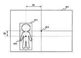
更に、カメラ雲台制御ステップ118では、テンプレートマッチングステップ106によって検出された侵入物体の位置と、入力画像の所定基準位置(即ち、撮像視野内の所定基準位置)、例えば、中心との変位によってカメラ雲台の制御を行なう。一例として、図8で示すような位置802に侵入物体が検出されたとする。この場合、侵入物体の中心位置をテンプレートの中心803とすると、画像の中心804からの変位dx、dyが算出される。
Further, in the camera
ここで、テンプレートの中心位置803が入力画像の中心804より所定量s以上左側(dx<−s)であればカメラ雲台を左にパンさせ、右側(dx>s)であれば右にパンさせる。侵入物体が画像の中心付近に存在する場合(−s≦dx≦s)は、カメラ雲台制御を制御する必要がないため、所定量sによってカメラ雲台制御を開始する位置を指定することができる。例えば、所定量sは、s=50である。
Here, if the
また、テンプレートの中心位置803が入力画像の中心804より上側(dy<−s))であればカメラ雲台を上にチルトさせ、下側(dy>s)であれば下にチルトさせる。
なお、dx及びdyの絶対値によってパンモータやチルトモータの制御速度を変化させるようにしても良い(dxあるいはdyの絶対値が大きいほど制御速度を大きくする)。
If the
Note that the control speed of the pan motor or tilt motor may be changed according to the absolute values of dx and dy (the control speed increases as the absolute value of dx or dy increases).
最後に第2の警報・モニタ表示ステップ119では、例えば侵入物体を追尾中であることを表す警報を鳴らして監視員に知らせる。
ここまでの処理が実行されていく過程を、図7によって説明する。図7は、テンプレートマッチングを逐次実行することによって侵入物体の位置を追跡する一例を表す図である。図7において、701は時刻t0−1におけるテンプレート画像を表しており、701aは時刻t0−1におけるテンプレートであり、702は時刻t0における入力画像である。画像702において、702aは時刻t0−1における侵入物体の位置(テンプレート701aの位置)を示す矩形領域、702bはテンプレートマッチングの対象となる領域(探索領域)を示す矩形領域を表す。
Finally, in the second alarm /
A process in which the processes so far are executed will be described with reference to FIG. FIG. 7 is a diagram illustrating an example of tracking the position of an intruding object by sequentially executing template matching. In FIG. 7, 701 represents a template image at time t0-1, 701a is a template at time t0-1, and 702 is an input image at time t0. In the
ここで、テンプレートマッチング処理709(テンプレートマッチングステップ106)を実行すると、テンプレートマッチングの探索領域702bの中でテンプレート701aに最も一致する画像702cで一致度が最も大きくなり、侵入物体は時刻t0において画像702cの位置に存在していることが分かる。即ち、侵入物体は矢印702dだけ移動したことが分かる。
Here, when the template matching process 709 (template matching step 106) is executed, the degree of matching is highest in the
次に、テンプレート更新処理710(テンプレート更新ステップ117)において、テンプレート701aに最も一致した画像702cを時刻t0における新たなテンプレートとして更新する。即ち、入力画像702から侵入物体の位置702cを切り出し、これをテンプレート画像703とし、侵入物体の画像702cを時刻t0における新たなテンプレート703aとして更新する。
Next, in template update processing 710 (template update step 117), the
この処理をカメラから逐次入力される入力画像に対して適用すると、時刻t0+1における入力画像704中にテンプレート703aの位置704aに基づいて探索領域704bを設定し、時刻t0におけるテンプレート画像703中のテンプレート703aを用いてテンプレートマッチング処理709によって侵入物体の位置704cを検出する。すると侵入物体は矢印704dのように移動したことが分かる。
When this processing is applied to an input image sequentially input from the camera, a
更にテンプレート更新処理710によって時刻t0+1におけるテンプレート画像705、および侵入物体のテンプレート705aを更新する。更に、時刻t0+2における入力画像706中にテンプレート705aの位置706aに基づいて探索領域706bを設定し、時刻t0+1におけるテンプレート画像705中のテンプレート705aを用いてテンプレートマッチング処理709によって侵入物体の位置706cを検出する。
Furthermore, the
すると侵入物体は矢印706dのように移動したことが分かる。さらにテンプレート更新処理710によって時刻t0+2におけるテンプレート画像707、および侵入物体のテンプレート707aを更新する。
Then, it can be seen that the intruding object has moved as indicated by an
更に、時刻t0+3における入力画像708中にテンプレート707aの位置708aに基づいて探索領域707bを設定し、時刻t0+2におけるテンプレート画像707中のテンプレート707aを用いてテンプレートマッチング処理709によって侵入物体の位置708cを検出する。すると侵入物体は矢印708dのように移動したことが分かる。すなわち、テンプレートマッチングを逐次実行することで侵入物体を追跡することができる。
Furthermore, a search area 707b is set based on the
ところで、前述のテンプレートマッチングを用いた侵入物体の追尾法では、追尾対象の侵入物体の向きが変化(例えば、侵入物体の人が右を向いたり、後ろを向いたり)すると、侵入物体とテンプレートマッチングによって検出される位置とのずれが大きくなり、正確かつ安定した追尾が行なえなくなるという問題がある。これは、テンプレートマッチングは、テンプレート内の高いコントラストの模様部分(輝度値の差が大きい部分)が一致するようにマッチングされるという性質があるためである。例えば、侵入物体が車両である場合において、はじめは正面を向いていて、車両のほとんどすべてをテンプレート内に捉えていた場合でも、その後進行方向(向き)が変わり横向きになってしまうと車両の前面部分だけしかテンプレートに捉えられなくなり、車両全体がテンプレート内に捉えていた時に比べて、テンプレートの中心が車両の中心から車両の前部に移動するため、侵入物体の位置がずれて検出されてしまう。 By the way, in the tracking method of the intruding object using the template matching described above, if the orientation of the intruding object to be tracked changes (for example, the person of the intruding object turns to the right or back), the intruding object matches the template. As a result, there is a problem that the deviation from the detected position becomes large and accurate and stable tracking cannot be performed. This is because template matching has a property that matching is performed so that high contrast pattern parts (parts having a large difference in luminance values) in the template match. For example, when the intruding object is a vehicle, the vehicle is initially facing the front and almost all of the vehicle is captured in the template. Only the portion can be captured by the template, and the center of the template moves from the center of the vehicle to the front of the vehicle compared to when the entire vehicle is captured in the template, so the position of the intruding object is detected with a shift. .
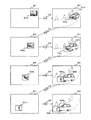
この現象を図9によって説明する。図9は、テンプレートマッチングを用いた侵入物体の追尾法でテンプレート内に侵入物体を捉えられなくなる現象を説明するために、撮像視野内で曲線を描く車道を通過する車両を侵入物体として追尾した場合の処理が実行されていく過程を示した図である。簡単のために、この図9では、カメラ雲台の制御は行なっていない場合の例を示している。 This phenomenon will be described with reference to FIG. FIG. 9 shows a case where a vehicle passing through a curved road in an imaging field is tracked as an intruding object in order to explain a phenomenon that the intruding object cannot be captured in the template by the tracking method of the intruding object using template matching. It is the figure which showed the process in which the process of is performed. For simplicity, FIG. 9 shows an example in which the camera pan head is not controlled.
901、903、905、907は、それぞれ、時刻t1−1、時刻t1、時刻t1+1、時刻t1+2におけるテンプレート画像、901a、903a、905a、907aは、それぞれ、時刻t1−1、時刻t1、時刻t1+1、時刻t1+2におけるテンプレートを表す。また、902、904、906、908は、それぞれ、時刻t1、時刻t1+1、時刻t1+2、時刻t1+3における入力画像、902a、904a、906a、908aは、それぞれ、時刻t1−1、時刻t1、時刻t1+1、時刻t1+2におけるテンプレートの位置(時刻t1−1、時刻t1、時刻t1+1、時刻t1+2における侵入物体の位置)、902b、904b、906b、906bは、それぞれ、時刻t1、時刻t1+1、時刻t1+2、時刻t1+3においてテンプレートマッチング処理によって検出された侵入物体の位置である。
901, 903, 905, and 907 are template images at time t1-1, time t1,
図9において、時刻t1−1で登録されているテンプレート901aは、車両のフロント部分がほぼ正面を向いている画像である。時刻t1では、このテンプレート901aを用いてテンプレートマッチング(テンプレートマッチング処理709)を行ない、侵入物体の移動した位置を検出すると共に、テンプレート901aをテンプレート903aに更新する(テンプレート更新処理710)。続いて、時刻t1+1ではテンプレート905aに更新され、時刻t1+2ではテンプレート907aに更新され、この処理を時刻t1+3まで行なうと、テンプレートは、追尾開始時刻t11で車両のライトなどがあるフロント部分を捉えていたものが、時刻t1+3では、車両の左側にずれて捉えている。この現象は、テンプレートマッチングが対象とする入力画像とテンプレート画像中のコントラストが高い画像部分のずれを小さくするようにマッチングが行なわれるように働くためで、この例では車両のライト部分がそれにあたる。そのため、図9のように、侵入物体が向って右から左に向きを変えるような場合には左側にずれ、向って左から右に向きを変えるような場合に右側にずれる。
In FIG. 9, the
さらに、時刻t1−1では、テンプレート901aの中に車両の画像だけが入っていたが、侵入物体が向きを変えて、侵入物体に対してテンプレートがずれたことによって、時刻t1+3ではテンプレート908b中に侵入物体以外の背景部分の画像が入り込んでしまう。このテンプレート908bのような追尾すべき侵入物体以外の画像を多く含んだテンプレートを用いてテンプレートマッチングを続けた場合には、侵入物体を捉えることができずに、テンプレートに入り込んだ背景部分とマッチングしてしまう。従って、テンプレートマッチングを用いた侵入物体追尾法は、侵入物体の向きが変化するような場合には、侵入物体の模様が見かけ上移動し、それに引っ張られてテンプレートの位置が侵入物体の位置からずれてしまうため、追尾対象である侵入物体を追尾している保証ができず、安定な追尾を行なうことができない。
Furthermore, at time t1-1, only the vehicle image was included in the
なお、本発明に係る先行出願には、例えば、例えば先行特許文献1がある。
このように、上記従来技術には、例えば、検出物体の向きの変化が大きい場合には安定な追尾が行なえなくなるという欠点があった。
本発明の目的は、上記従来技術の欠点を除去しうる物体追尾方法及び物体追尾装置を提供するにある。
As described above, the conventional technique has a drawback that, for example, stable tracking cannot be performed when a change in the direction of the detected object is large.
An object of the present invention is to provide an object tracking method and an object tracking apparatus that can eliminate the drawbacks of the prior art.
本発明の別の目的は、例えば、検出物体の向きの変化が大きい場合にも、正確に検出物体を検出し、追尾することができる、信頼性が高く安定に動作する物体追尾方法及び物体追尾装置を提供することにある。 Another object of the present invention is to provide a highly reliable and stable object tracking method and object tracking that can accurately detect and track a detected object even when the orientation of the detected object is large, for example. To provide an apparatus.
本発明の物体追尾方法は、撮像装置から得られる画像信号に基づいて撮像画像中の物体を検出し追跡する物体追尾方法において、前記撮像装置から取得した画像から前記物体の一部を含む所定サイズのテンプレート画像を作成するテンプレート画像作成ステップと、前記撮像装置から異なる時刻に取得した2フレーム以上の画像に基づいて、該フレーム間での画像の変化領域を検出する画像変化検出ステップと、該検出された画像の変化領域に基づいて該物体の位置を検出し、該検出された物体位置を前記テンプレート画像に代えて新たなテンプレート画像とする、物体位置修正ステップとを備える。 The object tracking method of the present invention is an object tracking method for detecting and tracking an object in a captured image based on an image signal obtained from the imaging device, and a predetermined size including a part of the object from an image acquired from the imaging device. A template image creating step for creating a template image, an image change detecting step for detecting a change region of an image between the frames based on images of two or more frames acquired at different times from the imaging device, and the detection An object position correcting step of detecting the position of the object based on the changed area of the image and using the detected object position as a new template image instead of the template image.
また、本発明の物体追尾方法において、前記画像変化検出ステップは、前記撮像装置の制御状態の停止時において、前記撮像装置から異なる時刻に取得した2フレームの画像を比較することによって、画像の変化領域を検出する。 Further, in the object tracking method of the present invention, the image change detecting step compares the two frame images acquired at different times from the imaging device when the control state of the imaging device is stopped, thereby changing the image. Detect areas.
また、本発明の物体追尾方法において、前記撮像装置の制御状態の停止とは、前記撮像装置の撮像方向が固定の状態を示す。
また、本発明の物体追尾方法において、更に、前記検出された物体位置と、前記撮像装置の撮像視野内の所定基準位置との関係に基づいて該撮像装置の撮像方向を制御するステップを備える。
In the object tracking method of the present invention, the stop of the control state of the imaging device indicates a state where the imaging direction of the imaging device is fixed.
The object tracking method according to the present invention further includes a step of controlling an imaging direction of the imaging device based on a relationship between the detected object position and a predetermined reference position in an imaging field of the imaging device.
また、本発明の物体追尾方法において、前記画像変化検出ステップは、前記撮像装置から異なる時刻に取得した2フレームの画像を比較し、最も多い差分或いは所定値以上の差分が検出された領域を前記物体の位置として検出する。 In the object tracking method of the present invention, the image change detection step compares two frame images acquired at different times from the imaging device, and determines an area in which the largest difference or a difference greater than a predetermined value is detected. Detect as the position of the object.
また、本発明の物体追尾方法において、前記画像変化検出ステップは、前記現在のテンプレート画像の位置に基づき該物体の位置を検出するための探索範囲を設定し、該設定された探索範囲において前記2フレーム間での画像の変化領域を検出し、前記物体位置修正ステップは、該変化された探索範囲において最も多い差分或いは所定値以上の差分が検出された領域を前記物体の位置として検出する。 Further, in the object tracking method of the present invention, the image change detection step sets a search range for detecting the position of the object based on the position of the current template image, and the 2 in the set search range. A change area of an image between frames is detected, and the object position correcting step detects, as the position of the object, an area where the largest difference or a difference greater than a predetermined value is detected in the changed search range.
また、本発明の物体追尾装置は、撮像装置から得られる画像信号に基づいて撮像画像中の物体を検出し追跡する物体追尾装置において、該撮像装置が取得した映像信号を逐次画像信号に変換する画像入力部と、前記画像入力部によって変換された前記画像信号を予め決めた手順で処理する処理部とを備え、前記処理部は、前記撮像装置から取得した画像から前記物体の一部を含む所定サイズのテンプレート画像を作成し、前記撮像装置から異なる時刻に取得した2フレーム以上の画像に基づいて、該フレーム間での画像の変化領域を検出し、該検出された画像の変化領域に基づいて該物体の位置を検出し、該検出された物体位置を前記テンプレート画像に代えて新たなテンプレート画像とするように構成される。 Further, the object tracking device of the present invention sequentially converts a video signal acquired by the imaging device into an image signal in an object tracking device that detects and tracks an object in a captured image based on an image signal obtained from the imaging device. An image input unit; and a processing unit that processes the image signal converted by the image input unit according to a predetermined procedure. The processing unit includes a part of the object from an image acquired from the imaging device. A template image of a predetermined size is created, an image change area between the frames is detected based on images of two or more frames acquired at different times from the imaging device, and based on the detected change area of the image The position of the object is detected, and the detected object position is used as a new template image instead of the template image.
また、本発明の物体追尾装置において、前記処理部は、前記撮像装置から異なる時刻に取得した2フレームの画像を比較し、最も多い差分或いは所定値以上の差分が検出された領域を前記物体の位置として検出するように構成される。 In the object tracking device of the present invention, the processing unit compares two frames of images acquired at different times from the imaging device, and determines an area where the largest difference or a difference greater than a predetermined value is detected. It is configured to detect as a position.
また、本発明の物体追尾装置において、前記処理部は、前記現在のテンプレート画像の位置に基づき該物体の位置を検出するための探索範囲を設定し、該設定された探索範囲において前記2フレーム間での画像の変化領域を検出し、該変化された探索範囲において最も多い差分或いは所定値以上の差分が検出された領域を前記物体の位置として検出するように構成される。 Further, in the object tracking device of the present invention, the processing unit sets a search range for detecting the position of the object based on the position of the current template image, and the two frames are detected in the set search range. The change area of the image is detected, and the area where the largest difference or the difference greater than a predetermined value is detected in the changed search range is detected as the position of the object.
また、本発明の物体追尾方法は、撮像装置から得られる画像信号に基づいて撮像画像中の物体を検出し追跡する物体追尾方法において、前記撮像装置から異なる時刻に取得した2フレーム以上の画像に基づいて、該フレーム間での画像の変化領域を検出する画像変化検出ステップと、該検出された画像の変化領域に基づいて該物体の位置を検出し、該検出された物体位置を現在の物体検出位置に代えて新たな物体検出位置とする、物体位置修正ステップとを備える。 The object tracking method of the present invention is an object tracking method for detecting and tracking an object in a captured image based on an image signal obtained from the imaging device. And an image change detecting step for detecting a change area of the image between the frames, and detecting the position of the object based on the detected change area of the image, and detecting the detected object position as the current object. An object position correcting step of setting a new object detection position instead of the detection position.
また、本発明の物体追尾方法において、画像変化検出ステップは、前記撮像装置から異なる時刻に取得した2フレームの画像を比較し、最も多い差分が検出された領域を前記物体の位置として検出する。 In the object tracking method of the present invention, the image change detection step compares two frames of images acquired at different times from the imaging device, and detects an area where the largest difference is detected as the position of the object.
また、本発明の物体追尾方法において、前記画像変化検出ステップは、前記撮像装置から異なる時刻に取得した2フレームの画像を比較し、所定値以上の差分が検出された領域を前記物体の位置として検出する。 In the object tracking method of the present invention, the image change detection step compares two frames of images acquired at different times from the imaging device, and sets a region where a difference greater than or equal to a predetermined value is detected as the position of the object. To detect.
また、本発明の物体追尾方法において、前記画像変化検出ステップは、前記撮像装置の制御状態の停止時において、前記撮像装置から異なる時刻に取得した2フレームの画像を比較することによって、画像の変化領域を検出する。 Further, in the object tracking method of the present invention, the image change detecting step compares the two frame images acquired at different times from the imaging device when the control state of the imaging device is stopped, thereby changing the image. Detect areas.
また、本発明の物体追尾方法において、前記撮像装置の制御状態の停止とは、前記撮像装置の撮像方向が固定の状態を示す。
また、本発明の物体追尾方法において、前記検出された物体位置と、前記撮像装置の撮像視野内の所定基準位置との関係に基づいて該撮像装置の撮像方向を制御するステップを備える。
In the object tracking method of the present invention, the stop of the control state of the imaging device indicates a state where the imaging direction of the imaging device is fixed.
The object tracking method according to the present invention further includes a step of controlling an imaging direction of the imaging device based on a relationship between the detected object position and a predetermined reference position within an imaging field of the imaging device.
また、本発明の物体追尾方法において、前記画像変化検出ステップは、前記現在の物体検出位置に基づき該物体の位置を検出するための探索範囲を設定し、該設定された探索範囲において前記2フレーム間での画像の変化領域を検出し、前記物体位置修正ステップは、該変化された探索範囲において最も多い差分が検出された領域を前記物体の位置として検出する。 In the object tracking method of the present invention, the image change detection step sets a search range for detecting the position of the object based on the current object detection position, and the two frames are set in the set search range. In the object position correction step, an area where the largest difference is detected in the changed search range is detected as the position of the object.
また、本発明の物体追尾方法において、前記画像変化検出ステップは、前記現在の物体検出位置に基づき該物体の位置を検出するための探索範囲を設定し、該設定された探索範囲を段階的に変化し、該変化された各探索範囲において前記2フレーム間での画像の変化領域を検出し、前記物体位置修正ステップは、該変化された探索範囲において最も多い差分が検出された領域を前記物体の位置として検出する。 In the object tracking method of the present invention, the image change detection step sets a search range for detecting the position of the object based on the current object detection position, and the set search range is stepwise. And a change area of the image between the two frames is detected in each changed search range, and the object position correcting step determines an area in which the largest difference is detected in the changed search range as the object. Detect as the position of.
また、本発明の物体追尾方法において、前記物体位置修正ステップは、前記変化された探索範囲において検出された変化領域において最も多い差分が所定値以上となると、該最も多い差分が検出された領域を前記物体の位置として検出する。 Further, in the object tracking method of the present invention, the object position correcting step may be configured such that when the largest difference in the changed area detected in the changed search range becomes a predetermined value or more, the area in which the largest difference is detected. The position of the object is detected.
また、本発明の物体追尾方法において、前記画像変化検出ステップは、該設定された探索範囲を段階的に拡大または移動する。
また、本発明の物体追尾方法において、前記画像変化検出ステップは、前記現在の物体検出位置に基づき該物体の位置を検出するための探索範囲を設定し、該設定された探索範囲において前記2フレーム間での画像の変化領域を検出し、前記物体位置修正ステップは、該変化された探索範囲において所定値以上の差分が検出された領域を前記物体の位置として検出する。
In the object tracking method of the present invention, the image change detection step expands or moves the set search range stepwise.
In the object tracking method of the present invention, the image change detection step sets a search range for detecting the position of the object based on the current object detection position, and the two frames are set in the set search range. In the image position change step, the object position correcting step detects an area where a difference of a predetermined value or more is detected in the changed search range as the position of the object.
また、本発明の物体追尾方法において、前記画像変化検出ステップは、前記現在の物体検出位置に基づき該物体の位置を検出するための探索範囲を設定し、該設定された探索範囲を段階的に変化し、該変化された各探索範囲において前記2フレーム間での画像の変化領域を検出し、前記物体位置修正ステップは、該変化された探索範囲において所定値以上の差分が検出された領域を前記物体の位置として検出する。 In the object tracking method of the present invention, the image change detection step sets a search range for detecting the position of the object based on the current object detection position, and the set search range is stepwise. And a change area of the image between the two frames is detected in each changed search range, and the object position correcting step includes an area in which a difference of a predetermined value or more is detected in the changed search range. The position of the object is detected.
また、本発明の物体追尾方法において、前記画像変化検出ステップは、該設定された探索範囲を段階的に拡大または移動する。
また、本発明の物体追尾方法は、撮像装置から得られる画像信号に基づいて撮像画像中の物体を検出し追跡する物体追尾方法において、前記撮像装置から取得した画像から前記物体の一部を含む所定サイズのテンプレート画像を作成するテンプレート画像作成ステップと、前記撮像装置から異なる時刻に取得した2フレーム以上の画像に基づいて、該フレーム間での画像の変化領域を検出する画像変化検出ステップと、該検出された画像の変化領域に基づいて該物体の位置を検出し、該検出された物体位置を前記テンプレート画像に代えて新たなテンプレート画像とする、物体位置修正ステップとを備える。
In the object tracking method of the present invention, the image change detection step expands or moves the set search range stepwise.
The object tracking method of the present invention includes a part of the object from the image acquired from the imaging device in the object tracking method of detecting and tracking an object in the captured image based on an image signal obtained from the imaging device. A template image creating step for creating a template image of a predetermined size; an image change detecting step for detecting a change region of an image between the frames based on images of two or more frames acquired at different times from the imaging device; An object position correcting step of detecting the position of the object based on the detected change area of the image, and using the detected object position as a new template image instead of the template image.
また、本発明の物体追尾方法において、前記画像変化検出ステップは、前記撮像装置から異なる時刻に取得した2フレームの画像を比較し、最も多い差分が検出された領域を前記物体の位置として検出する。 In the object tracking method of the present invention, the image change detection step compares two frames of images acquired at different times from the imaging device, and detects an area where the largest difference is detected as the position of the object. .
また、本発明の物体追尾方法において、前記画像変化検出ステップは、前記撮像装置から異なる時刻に取得した2フレームの画像を比較し、所定値以上の差分が検出された領域を前記物体の位置として検出する。 In the object tracking method of the present invention, the image change detection step compares two frames of images acquired at different times from the imaging device, and sets a region where a difference greater than or equal to a predetermined value is detected as the position of the object. To detect.
また、本発明の物体追尾方法において、前記画像変化検出ステップは、前記撮像装置の制御状態の停止時において、前記撮像装置から異なる時刻に取得した2フレームの画像を比較することによって、画像の変化領域を検出する。 Further, in the object tracking method of the present invention, the image change detecting step compares the two frame images acquired at different times from the imaging device when the control state of the imaging device is stopped, thereby changing the image. Detect areas.
また、本発明の物体追尾方法において、前記撮像装置の制御状態の停止とは、前記撮像装置の撮像方向が固定の状態を示す。
また、本発明の物体追尾方法において、前記検出された物体位置と、前記撮像装置の撮像視野内の所定基準位置との関係に基づいて該撮像装置の撮像方向を制御するステップを備える。
In the object tracking method of the present invention, the stop of the control state of the imaging device indicates a state where the imaging direction of the imaging device is fixed.
The object tracking method according to the present invention further includes a step of controlling an imaging direction of the imaging device based on a relationship between the detected object position and a predetermined reference position within an imaging field of the imaging device.
また、本発明の物体追尾方法において、前記画像変化検出ステップは、前記現在のテンプレート画像の位置に基づき該物体の位置を検出するための探索範囲を設定し、該設定された探索範囲において前記2フレーム間での画像の変化領域を検出し、前記物体位置修正ステップは、該変化された探索範囲において最も多い差分が検出された領域を前記物体の位置として検出する。 Further, in the object tracking method of the present invention, the image change detection step sets a search range for detecting the position of the object based on the position of the current template image, and the 2 in the set search range. A change area of an image between frames is detected, and the object position correcting step detects an area where the largest difference is detected in the changed search range as the position of the object.
また、本発明の物体追尾方法において、前記画像変化検出ステップは、前記現在のテンプレート画像の位置に基づき該物体の位置を検出するための探索範囲を設定し、該設定された探索範囲を段階的に変化し、該変化された各探索範囲において前記2フレーム間での画像の変化領域を検出し、前記物体位置修正ステップは、該変化された探索範囲において最も多い差分が検出された領域を前記物体の位置として検出する。 In the object tracking method of the present invention, the image change detection step sets a search range for detecting the position of the object based on the position of the current template image, and the set search range is stepwise. In the changed search range, the change area of the image between the two frames is detected, and the object position correcting step determines the area where the most difference is detected in the changed search range. Detect as the position of the object.
また、本発明の物体追尾方法において、前記物体位置修正ステップは、前記変化された探索範囲において検出された変化領域において最も多い差分が所定値以上となると、該最も多い差分が検出された領域を前記物体の位置として検出する。 Further, in the object tracking method of the present invention, the object position correcting step may be configured such that when the largest difference in the changed area detected in the changed search range becomes a predetermined value or more, the area in which the largest difference is detected. The position of the object is detected.
また、本発明の物体追尾方法において、前記画像変化検出ステップは、該設定された探索範囲を段階的に拡大または移動する。
また、本発明の物体追尾方法において、前記画像変化検出ステップは、前記現在のテンプレート画像の位置に基づき該物体の位置を検出するための探索範囲を設定し、該設定された探索範囲において前記2フレーム間での画像の変化領域を検出し、前記物体位置修正ステップは、該変化された探索範囲において所定値以上の差分が検出された領域を前記物体の位置として検出する。
In the object tracking method of the present invention, the image change detection step expands or moves the set search range stepwise.
Further, in the object tracking method of the present invention, the image change detection step sets a search range for detecting the position of the object based on the position of the current template image, and the 2 in the set search range. A change area of an image between frames is detected, and the object position correcting step detects an area where a difference of a predetermined value or more is detected in the changed search range as the position of the object.
また、本発明の物体追尾方法において、前記画像変化検出ステップは、前記現在のテンプレート画像の位置に基づき該物体の位置を検出するための探索範囲を設定し、該設定された探索範囲を段階的に変化し、該変化された各探索範囲において前記2フレーム間での画像の変化領域を検出し、前記物体位置修正ステップは、該変化された探索範囲において所定値以上の差分が検出された領域を前記物体の位置として検出する。 In the object tracking method of the present invention, the image change detection step sets a search range for detecting the position of the object based on the position of the current template image, and the set search range is stepwise. The change area of the image between the two frames is detected in each of the changed search ranges, and the object position correcting step is an area in which a difference of a predetermined value or more is detected in the changed search range. Is detected as the position of the object.
また、本発明の物体追尾方法において、前記画像変化検出ステップは、該設定された探索範囲を段階的に拡大または移動する。
また、本発明の侵入物体追尾方法は、監視対象領域に侵入する物体を監視対象領域を撮像して取得した画像信号に基づいて検出し、検出した結果に基づいて撮像装置を搭載するカメラ雲台を制御して侵入物体を追尾する方式の侵入物体追尾方法において、カメラ雲台の制御状態に応じて撮像装置から異なる時刻に取得した少なくとも2フレーム以上の画像信号に基づいて画像信号の変化領域を検出する画像信号変化検出ステップと、画像信号変化検出ステップで検出された画像信号の変化領域に基づいて侵入物体の正確な位置を検出して侵入物体の位置情報を修正する侵入物体位置修正ステップとを備えることによって達成される。
In the object tracking method of the present invention, the image change detection step expands or moves the set search range stepwise.
Further, the intruding object tracking method of the present invention detects an object entering the monitoring target area based on an image signal acquired by imaging the monitoring target area, and mounts an imaging device based on the detection result. In the intruding object tracking method of tracking the intruding object by controlling the image signal, the change area of the image signal is determined based on the image signal of at least two frames or more acquired from the imaging device at different times according to the control state of the camera pan head. An image signal change detecting step for detecting, and an intruding object position correcting step for correcting the position information of the intruding object by detecting an accurate position of the intruding object based on the change area of the image signal detected in the image signal change detecting step; It is achieved by comprising.
また好ましくは、本発明の侵入物体追尾方法の画像信号変化検出ステップは、カメラ雲台停止時に撮像装置から異なる時刻に取得した2フレームの画像信号を比較することによって画像信号の変化領域を検出するものである。 Also preferably, the image signal change detection step of the intruding object tracking method of the present invention detects a change area of the image signal by comparing two frames of image signals acquired at different times from the imaging device when the camera head is stopped. Is.
またさらに好ましくは、本発明の侵入物体追尾方法の侵入物体位置修正ステップは、侵入物体の位置情報に基づいて侵入物体の正確な位置を検出する対象領域を段階的に拡大し、画像信号変化検出ステップで得られた画像信号の変化領域と、対象領域に基づいて侵入物体の正確な位置を検出して侵入物体の位置情報を修正するものである。 Still more preferably, the intruding object position correcting step of the intruding object tracking method of the present invention stepwise expands the target area for detecting the exact position of the intruding object based on the position information of the intruding object, and detects image signal change. The position information of the intruding object is corrected by detecting the exact position of the intruding object based on the change area of the image signal obtained in the step and the target area.
また、本発明の侵入物体監視装置は、監視対象領域を撮像する撮像装置から入力される画像信号の変化部分を検出し、検出した結果に基づいて撮像装置を搭載するカメラ雲台を制御することにより侵入物体を追尾する方式の侵入物体追尾装置において、監視対象領域を逐次撮像する装置と、撮像装置が取得した映像信号を逐次画像信号に変換する画像入力部と、カメラ雲台を制御する雲台制御部と、画像入力部によって変換された画像信号を予め決めた手順で処理する処理手段を備え、記処理手段は、画像入力部を介して得られた画像信号の変化領域を検出し、変化領域に基づいて雲台制御部を介してカメラ雲台を制御し、侵入物体を撮像装置の視野内に捉えながら侵入物体を追尾するものである。 Further, the intruding object monitoring device of the present invention detects a changing portion of an image signal input from an imaging device that images a monitoring target region, and controls a camera pan mounted with the imaging device based on the detected result. In an intruding object tracking device that tracks an intruding object by a device, a device that sequentially images a monitoring target region, an image input unit that sequentially converts a video signal acquired by the imaging device into an image signal, and a cloud that controls a camera platform A table control unit and a processing unit that processes the image signal converted by the image input unit according to a predetermined procedure, and the processing unit detects a change region of the image signal obtained through the image input unit; The camera head is controlled via the head control unit based on the change area, and the intruding object is tracked while the intruding object is captured in the field of view of the imaging apparatus.
本発明によれば、検出物体が向きを変えた場合に検出物体に対してテンプレートがずれる場合があり、テンプレートに追尾すべき検出物体以外の画像を多く含んでしまい検出物体を捉えることができずに、テンプレートに入り込んだ背景部分とマッチングしてしまうという従来の問題を除去できる。更に、検出物体の向きの変化が大きい場合にも、正確に物体を検出し、追尾することができる。従って、信頼性が高く安定に動作する物体追尾方法及び物体追尾装置を提供することができる。 According to the present invention, when the detected object changes its orientation, the template may be shifted from the detected object, and the template includes a lot of images other than the detected object to be tracked, and the detected object cannot be captured. In addition, the conventional problem of matching with the background portion that has entered the template can be eliminated. Furthermore, even when the change in the direction of the detected object is large, the object can be accurately detected and tracked. Therefore, it is possible to provide an object tracking method and an object tracking apparatus that operate stably with high reliability.
以下、本発明による侵入物体追尾方法および侵入物体追尾装置について、図示の実施の形態により詳細に説明する。
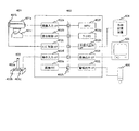
先ず、図4は、本発明の一実施例が適用された監視システムのハードウエア構成の一例である。401は撮像装置である。撮像装置401はカメラ401aとズームレンズ401b、及びカメラ雲台(電動旋回台)401cで少なくとも構成されている。次に、402は処理装置で、画像入力部(画像入力I/F)402aと雲台制御部(雲台制御I/F)402b、レンズ制御部(レンズ制御I/F)402c、操作入力部(操作入力I/F)402d、画像メモリ402e、MPU(マイクロプロセッシングユニット、Micro Processing Unit)402f、ワークメモリ402g、外部入出力部(外部入出力I/F)402h、画像出力部(画像出力I/F)402i、警報出力部(警報出力I/F)402j、それにデータバス402kで構成され、これに、操作手段403と外部記憶装置404、画像モニタ405、更に警告灯406が組合わされている。
Hereinafter, an intruding object tracking method and an intruding object tracking apparatus according to the present invention will be described in detail with reference to the illustrated embodiments.
4 is an example of a hardware configuration of a monitoring system to which an embodiment of the present invention is applied.
更に、操作手段403は、ジョイスティック403aと第1のボタン403b、第
2のボタン404cで構成されている。そして、カメラ401aの出力は画像入力部
402aを介してデータバス402kに接続され、ズームレンズ401bの制御部はレンズ制御部402cを介してデータバス402kに接続され、カメラ401aを搭載するカメラ雲台401cは雲台制御部402bを介してデータバス402kに接続され、操作手段403の出力は操作入力部402dを介してデータバス402kに接続されている。
Further, the operation means 403 includes a
また、外部記憶装置404は外部入出力部402hを介してデータバス402kに
接続され、監視用の画像モニタ405は画像出力部402iを介してデータバス40
2kに接続され、警告灯406は警報出力部402jを介してデータバス402kに接続されている。一方、MPU402gとワークメモリ402gは、そのままデータバス402kに接続されている。
The
The
ここで、カメラ401aは、監視対象領域を所定の視野内に捉え、監視対象領域撮像して映像信号を出力する。このため、ズームレンズ401bを備え、カメラ雲台401cに搭載されている。そして、撮像された映像信号は、画像入力部402aからデータバス402kを介して画像メモリ402eに蓄積される。外部記憶装置404は、プログラムやデータなどを記憶する働きをし、プログラムやデータなどが必要に応じて外部入出力部402hを介してワークメモリ402gに読み込まれ、また反対にワークメモリ402gから画像記憶装置404に保存される。
Here, the
MPU402fは、外部記憶装置404に保存され、処理手段402動作時にワークメモリ402gに読み込まれたプログラムに従って処理を実行し、ワークメモリ4
02g内で画像メモリ402eに蓄積された画像の解析を行なう。そして、この処理
結果に応じて、MPU402fは、ズームレンズ401bを制御し、カメラ雲台401cを制御して、カメラ401aの撮像視野を変えると共に、必要に応じて監視モニタ405に侵入物体検出結果の画像を表示し、警告灯406を点灯させる。
The
The image stored in the image memory 402e is analyzed within 02g. Then, in accordance with this processing result, the
次に、本発明の実施の形態の動作の一例について説明する。ここで、以下に説明する実施形態は、図4で説明したハードウエア構成により動作するもので、この本発明の第1の実施例の動作を、図2により説明する。ここで、この図2は、本発明の第1の実施例における処理プロセスの一例をフローチャートで示した図である。 Next, an example of the operation of the embodiment of the present invention will be described. Here, the embodiment described below operates with the hardware configuration described in FIG. 4, and the operation of the first embodiment of the present invention will be described with reference to FIG. FIG. 2 is a flowchart showing an example of the processing process in the first embodiment of the present invention.
この図2の処理プロセスは、まず初期化処理ステップ101から開始される。この初期化処理ステップ101では、画像メモリ領域や記録領域の初期化を実行する。また、外部記憶装置404に記録した基準背景画像を読み込んで画像メモリ402eに記憶する。画像メモリ領域は、侵入物体追尾処理に使用するためのメモリ領域で、画像メモリ402e内に確保される。また、記録領域は、ワークメモリ402g内に確保された領域で、処理プロセスの処理に必要な変数などを記憶する。
The processing process of FIG. 2 starts from an
次に、侵入物体検出処理ステップ102は、図5、6を用いて説明した従来方式の侵入物体検出処理ステップ102と同じ処理を行なう。図2では、侵入物体検出処理ステップ102を構成する各ステップは、1つのステップとして省略して表示している。また、各ステップの動作については、従来方式の処理動作で説明したため、ここでは説明を省略する。
Next, the intruding object
次に第1の警報・モニタ表示ステップ103では、例えば画像モニタ405に検出した侵入物体の画像を表示し、警告灯406を点灯させ、監視対象領域内に侵入物体が存在することを意味する報知が行なわれる。または警報を示す画像、文字等を画像モニタ405に表示しても良い。
Next, in the first alarm /
画像入力ステップ105では、画像入力部402aを介して、カメラ401aで撮像された画像信号を入力し、例えば横方向320画素、高さ方向240画素、1画素当たりデータビット数8(320×240画素、8bit/画素)の入力画像を取得する。この際、前の処理フレーム(1巡前のステップの処理で)で取得した入力画像を画像メモリ402eに記憶しておく。画像メモリ402eに記憶された入力画像は、それが入力された時刻から所定の時間(例えば10秒)が経過した場合に消去される。
In the
次に、カメラ雲台停止判定ステップ109では、カメラ雲台401cが停止中か、即ち、カメラの撮像方向(言い替えれば、カメラの光軸方向)が固定中か否かを判定する。停止中の場合はフレーム間差分処理ステップ110へ分岐し、停止中でない場合はカメラ雲台制御ステップ118へ分岐する(理由は後述する)。
Next, in a camera head
フレーム間差分処理ステップ110では、フレーム間差分法の処理を実行する。フレーム間差分法とは、図6で説明した従来技術で使用している侵入物体の検出方法である差分法の基準背景画像602の代わりに画像メモリ402eに記憶された前処理フレームの入力画像を使用する。即ち、異なる時刻に得られた2フレームの入力画像を差分法に適用すると、入力画像中で動いている部分(画素値に変化がある部分)が検出される。侵入物体は動いているため、侵入物体の画素値に差分が生じるため、侵入物体の検出が行なえるのである。この差分法は、特にフレーム間差分法と呼ばれ広く使用されている。なお、図6で説明した入力画像と基準背景画像との差分を求める方法は、背景差分法と呼ばれている。
In the inter-frame
次に差分量最大位置探索ステップ112では、フレーム間差分処理ステップ110で得られた差分画像から、差分が多く含まれる領域を探索する。この処理を図15によって説明する。図15(1)は、画像入力ステップ105で入力した入力画像1501、図15(2)は、画像メモリ402eに記憶された入力画像1502を表す。入力画像1502は、入力画像1501に比べ取得時刻が所定の時間(例えば1秒)離れているものを使用する。すると、差分画像として図15(3)の斜線で囲んだ領域1503が得られる。
Next, in the difference amount maximum
ここで、侵入物体位置1503a(この時点では、現在の侵入物体の位置は分からないため前処理フレームでの侵入物体の位置を使用する)に対し、X軸、Y軸方向にそれぞれ所定の画素d分(例えばd=100画素)だけ拡大した領域を探索領域1503bとして設定し、その領域内の画素の差分の累積値を、X軸、Y軸に対して投影すると、図15(3)で示す投影像1503c、1503dのようになる。これらを、それぞれhx(x)、hy(y)と表記する。なお、図15(3)は、分かりやすくするために差分画像上に投影したグラフを重ねて表示している。
Here, with respect to the intruding
次に、図15(4)は、探索領域内の画素の差分の累積値をX軸に投影したhx(x)を示し、点線で示した領域1503eは、前処理フレームで侵入物体の検出位置を表わす範囲である。ここで、侵入物体の幅tx(侵入物体検出処理ステップ102で検出された侵入物体の幅)内に最も差分の多い位置を検出する。この例では、実線の領域1503fになる。これを式で表すと式(2)のようになる。
Next, FIG. 15 (4) shows hx (x) obtained by projecting the accumulated value of pixel differences in the search area on the X axis, and an
これを式で表すと式(3)のようになる。 This can be expressed by the following equation (3).
従って、フレーム間差分処理ステップ110によって、差分が多く存在する位置(x1,y1)が検出される。
なお、本実施例では、式(2)、(3)で表される通り、x1もしくはy1をx0−d<x1<x0+d、y0−d<y1<y0+dと変化させた場合に、x1<x<x1+dx、y1<y<y1+dyにおいてhx(x)、hy(y)の累積値が最も大きくなるx1、y1を求めている。これに代わり、x0−d<x1<x0+d、y0−d<y1<y0+dと変化させる過程で式(2)のΣhx(x1+i)、i=0〜tx−1、式(3)のΣhy(y1+j)、j=0〜ty−1が所定のしきい値を超えた場合に式(2)、(3)の計算を中止し、その時のx1もしくはy1を侵入物体位置の修正位置としても良い。この場合、所定のしきい値とは、例えば累積値の最大値255×(dy+2d)(y軸に対しては255×(dx+2d))の30%の値を設定する。この値によって検出される範囲は、差分の最大累積値の30%以上の差分を含む部分となり、これによって式(2)、(3)の計算量を減らすことができる。
Therefore, the position (x1, y1) where there are many differences is detected by the inter-frame
In this embodiment, as expressed by the equations (2) and (3), when x1 or y1 is changed as x0-d <x1 <x0 + d and y0-d <y1 <y0 + d, x1 <x <X1 + dx, y1 <y <y1 + dy, x1 and y1 at which the accumulated values of hx (x) and hy (y) are the largest are obtained. Instead, Σhx (x1 + i), i = 0 to tx−1 in equation (2), Σhy (y1 + j in equation (3) in the process of changing to x0−d <x1 <x0 + d and y0−d <y1 <y0 + d. ), When j = 0 to ty−1 exceeds a predetermined threshold value, the calculation of equations (2) and (3) may be stopped, and x1 or y1 at that time may be used as the correction position of the intruding object position . In this case, for example, the predetermined threshold value is set to a 30% value of the maximum cumulative value 255 × (dy + 2d) (255 × (dx + 2d) for the y-axis). The range detected by this value is a portion including a difference of 30% or more of the maximum accumulated difference value, and this can reduce the amount of calculation of equations (2) and (3).
以上の方法は、フレーム間差分によって得られた差分をX軸方向、Y軸方向に投影して、投影した差分量に基づいて差分が最大となる領域を求め、侵入者の位置を修正するものである。この方法以外にも、探索範囲内であってテンプレートサイズの領域を、例えば左上から右下へと走査し、領域内に含まれる差分の合計量が最も大きくなる部分を検出して、その部分の位置を侵入物体の位置として修正する方法を用いても良い。またこの方法で、走査中に領域内の差分の合計量が所定の値以上になった場合に走査を中止し、その領域を侵入物体の位置として修正しても良い。 In the above method, the difference obtained by the inter-frame difference is projected in the X-axis direction and the Y-axis direction, the area where the difference is maximum is obtained based on the projected difference amount, and the position of the intruder is corrected. It is. In addition to this method, a template size area within the search range is scanned, for example, from the upper left to the lower right, and the part where the total amount of differences included in the area is the largest is detected, and A method of correcting the position as the position of the intruding object may be used. Further, in this method, when the total amount of differences in the area becomes equal to or larger than a predetermined value during scanning, the scanning may be stopped and the area may be corrected as the position of the intruding object.
次に、差分量判定ステップ201では、検出した差分が多く存在する領域(x1,y1)−(x1+tx,y1+ty)内の差分の合計値を求め、その値がtx×ty×th×0.1(この値は検出した領域内にしきい値の1割相当の差分が含まれているかを判定するものである)未満であった場合には、差分量が少ない、即ち、検出された領域内の動く物体は侵入物体ではないとして侵入物体検出処理ステップ102へ分岐する。また、その値がtx×ty×th×0.1以上であった場合には差分量が多い、即ち、検出された領域内の動く物体は侵入物体であるとして侵入物体位置修正ステップ115へ分岐する。ここで、この値0.1は検出した領域内にしきい値の、例えば、1割相当の差分が含まれているかを判定するものである。なお、0.1(1割)は、一例であり、実際のシステムの設定状況に応じて任意に設定すればよい。
Next, in the difference
そして、侵入物体位置修正ステップ115では、検出された位置(x1,y1)を侵入物体の存在する位置(x0,y0)と置きかえる。
なお、カメラ雲台停止判定ステップ109によって、カメラ雲台401cが停止している場合にのみフレーム間差分処理ステップ110から侵入物体位置修正ステップ115が実行されるようになっているが、フレーム間差分法は、異なる時刻に得られた2フレームの入力画像を比較することによって行なわれるため、カメラ雲台401cが動いている間はフレーム間差分を実行することができないためである。
In the intruding object
Note that the inter-frame
次に、カメラ雲台制御ステップ118は、図5と図8を用いて説明した従来のカメラ雲台制御方法と同様にカメラ雲台を制御する。さらに、第2の警報・モニタ表示ステップ119では、例えば画像モニタ405に追尾中の侵入物体の画像を表示し、警告灯406を点灯させ、監視対象領域内の侵入物体を追尾中であることを意味する報知が行なわれる。または侵入物体を追尾中であることを表す警報を示す画像、文字等を画像モニタ405に表示しても良い。
Next, the camera
つまり、この図2の実施例によれば、検出した領域内には動く物体である侵入物体が存在し、テンプレートマッチングを使用した侵入物体追尾方法で、追尾すべき侵入物体以外の画像を多く含んだテンプレートを用いてテンプレートマッチングを続けた場合には、侵入物体を捉えることができずに、テンプレートに入り込んだ背景部分とマッチングしてしまい、追尾対象である侵入物体を追尾している保証ができず、安定な追尾を行なうことができないという問題を解決することができ、確実に動く物体である侵入物体を捉え追尾することができる。以上のような結果、侵入物体追尾処理の性能を向上させることができ、信頼性の高い監視システムが容易に構築できる。 That is, according to the embodiment of FIG. 2, there are intruding objects that are moving objects in the detected area, and the intruding object tracking method using template matching includes many images other than the intruding objects to be tracked. If you continue template matching using a template, you cannot guarantee that the intruding object is being tracked by matching the background part that has entered the template without being able to catch the intruding object. Therefore, the problem that stable tracking cannot be performed can be solved, and an intruding object that is a moving object can be reliably captured and tracked. As a result, the performance of the intruding object tracking process can be improved, and a highly reliable monitoring system can be easily constructed.
次に、本発明の第2の実施例の動作を、図3により説明する。ここで、この図3は、本発明の第2の実施例における処理プロセスの一例をフローチャートで示したものである。
この図3の処理プロセスは、図2で表される処理プロセスに、図5で示される従来法のテンプレートマッチングを用いた侵入物体追尾方法を組合わせたものであり、差分量判定ステップ113、及び侵入物体停止判定ステップ116以外は、すでに説明しているため、ここでは説明は省略する。ただし、差分量最大位置探索ステップ112については、図2の処理プロセスのステップ112とは若干異なるので、この点は図10を用いて後述する。
Next, the operation of the second embodiment of the present invention will be described with reference to FIG. FIG. 3 is a flowchart showing an example of the processing process in the second embodiment of the present invention.
The processing process of FIG. 3 is a combination of the processing process shown in FIG. 2 with the intruding object tracking method using template matching of the conventional method shown in FIG. Since steps other than the intruding object
この処理プロセスでは、先ずテンプレートマッチングステップ106から第1の侵入物体位置修正ステップ108までの処理で、テンプレートマッチングによって侵入物体の位置を検出する。ただし、検出された侵入物体の位置には、上記従来技術の問題のように侵入物体とテンプレートの位置がずれている可能性があるため、続くカメラ雲台停止判定ステップ109から第2の侵入物体位置修正ステップ115までの処理で侵入物体の位置を正しい位置に補正するようにしている。
In this processing process, first, in the processing from the
ここで、前記第1の実施例での差分量判定ステップ201では、検出した位置の差分量が所定値以下であった場合に侵入物体追尾を中止し、再び侵入物体検出処理ステップ102へ戻る構成になっていたが、図3の実施例での差分量判定処理ステップ113は、差分量が所定値以下であっても侵入物体追尾を続けるようにしている。
Here, in the difference
ただし、差分量が所定値以下である場合には、侵入物体位置の修正は行なわず、侵入物体停止判定ステップ116へ分岐するようにしている。
次に、侵入物体停止判定ステップ116では、検出した侵入物体の位置が所定時間(例えば10秒)変わらない場合には侵入物体検出処理ステップ102へ分岐し、検出した侵入物体の位置が変わっている場合にはテンプレート更新ステップ117へ分岐する。
However, when the difference amount is equal to or smaller than the predetermined value, the intruding object position is not corrected, and the intruding object
Next, in the intruding object
上述の本発明の第1の実施例では、フレーム間差分法のみを使って侵入物体の位置を検出している。しかし、フレーム間差分法は、侵入物体の動きが止まった場合には差分が現れなくなってしまうため、すぐさま侵入物体追尾を中止し、新たな侵入物体を探すようになってしまう。そこで、この本発明の第2の実施例では、テンプレートマッチングを使用することで、侵入物体の動きが止まった場合でも所定時間内(上記例では10秒)であれば侵入物体を追尾し続けることができるようにする。 In the first embodiment of the present invention described above, the position of the intruding object is detected using only the inter-frame difference method. However, in the interframe difference method, when the movement of the intruding object stops, the difference does not appear, so the intruding object tracking is immediately stopped and a new intruding object is searched. Therefore, in the second embodiment of the present invention, by using template matching, even if the movement of the intruding object stops, the intruding object is continuously tracked within a predetermined time (10 seconds in the above example). To be able to.
この処理プロセスの流れを図11によって説明する。図11は、本発明の第2の実施例での処理が実行されていく過程の一例を表す図であり、図9で示した撮像視野内で曲線を描く車道を通過する車両を侵入物体として追尾した場合の図である。 The flow of this processing process will be described with reference to FIG. FIG. 11 is a diagram illustrating an example of a process in which processing according to the second embodiment of the present invention is executed, and a vehicle passing through a curved road in the imaging field of view illustrated in FIG. 9 is defined as an intruding object. It is a figure at the time of tracking.
なお、図11では、フレーム間差分処理110と差分量最大位置検索112の効果を説明するために、カメラ雲台の制御は行っていない場合の例を示している。カメラ雲台制御処理とフレーム間差分処理の動作タイミングについては後述する。1101、1103、1105、1107は、それぞれ、時刻t1−1、時刻t1、時刻t1+1、時刻t1+2におけるテンプレート画像、1101a、1103a、1105a、1107aは、それぞれ、時刻t1−1、時刻t1、時刻t1+1、時刻t1+2におけるテンプレートを表す。また、1102、1104、1106、1108は、それぞれ、時刻t1、時刻t1+1、時刻t1+2、時刻t1+3における入力画像、1102b、1104b、1106b、1108bは、それぞれ、時刻t1−1、時刻t1、時刻t1+1、時刻t1+2におけるテンプレートの位置(時刻t1−1、時刻t1、時刻t1+1、時刻t1+2における侵入物体の位置)、1102a、1104a、1106a、1108aは、それぞれ、時刻t1、時刻t1+1、時刻t1+2、時刻t1+3においてテンプレートマッチング処理によって検出された侵入物体の位置である。
In addition, in FIG. 11, in order to demonstrate the effect of the
図11において、時刻t1−1で登録されているテンプレート1101aは、車両のフロント部分がほぼ正面を向いている画像である。時刻t1では、このテンプレート1101aを用いてテンプレートマッチング(テンプレートマッチング処理709)を行ない、侵入物体の移動した位置を検出すると共に、フレーム間差分法(フレーム間差分処理ステップ110から侵入物体補正処理ステップ115)によって侵入物体位置を正確に補正し、更にテンプレート1101aをテンプレート1103aに更新する(テンプレート更新処理710)。
In FIG. 11, the
続いて、時刻t1+1ではテンプレート1105aに更新され、時刻t1+2ではテンプレート1107aに更新され、この処理を時刻t1+3まで行なうと、テンプレートは、追尾開始時刻t1において車両のライトなどがあるフロント部分を捉えていた。しかし、時刻t1+3において、図9で示される従来技術では車両の左側にずれて捉えている(テンプレート907a)のに対して、本発明の第2の実施例ではテンプレートは正確に侵入物体を捉えている(テンプレート1107a)。
Subsequently, at
従って、図11のように、侵入物体が向きを変えるような場面でも、従来のテンプレートマッチングのみを使ったときに生じる侵入物体の向きの変化に伴う侵入物体とテンプレートのずれを解決することができ、正確に侵入物体を追尾することができる。 Therefore, even when the intruding object changes its orientation as shown in FIG. 11, the deviation between the intruding object and the template due to the change in the intruding object orientation that occurs when only the conventional template matching is used can be solved. , Can accurately track intruding objects.
また、本実施形態によれば、テンプレートマッチングステップ106によって、侵入物体の大まかな位置(範囲)を特定し、この特定された範囲(現在のテンプレートの位置)に基づき探索範囲を設定し、フレーム間差分処理110、及び、差分量最大位置探索112を行っている。従って、本発明の第1の実施例の範囲(上記例ではd=100画素)に比べて例えばd=50画素などのように小さくできるため、フレーム間差分法に関わる計算量を低減することができる。
Further, according to the present embodiment, the rough position (range) of the intruding object is specified by the
ここで、第2の実施例における差分量最大位置探索ステップ112の処理の様子を図10に示す。第1の実施例の図15と同様の部分の説明は省略するが、図10(3)に示すように、テンプレートマッチングにより検出された侵入物体位置(現在のテンプレート位置)1003aに対し、X軸、Y軸方向にそれぞれ所定の画素d(例えば、d=50画素)だけ拡大した領域が探索領域1003bとして設定される。
Here, FIG. 10 shows a state of processing in the difference amount maximum
さらに、第2の実施例によれば、TVカメラの撮像視野内に複数の物体が存在した場合に、第1の実施例に比べて侵入物体をより正確に追尾できるという効果もある。この効果を図13(1)、(2)を用いて説明する。図13(1)は、撮像視野内の車両1301aを追尾中に、車両より手前に別の物体1301bが存在する例を示している。物体1301bは、車両1301aよりも手前に存在するため、見かけの大きさ、見かけの速度が車両1301aよりも大きい。このような場合、フレーム間差分処理によって得られる差分は、物体1301bの方が大きくなる。今、前フレームの侵入物体の検出位置を表す範囲を1301cとすると、本発明の第1の実施例によると、フレーム間差分処理の対象となる範囲は、1301dのようになる。この場合、範囲1301dの中に物体1301bが写っており、このような場面で差分量最大位置探索ステップ112を実行すると、得られる差分の累積値が最大となる範囲は、物体1301bの部分になってしまう。
Furthermore, according to the second embodiment, when there are a plurality of objects in the imaging field of view of the TV camera, there is an effect that an intruding object can be tracked more accurately than in the first embodiment. This effect will be described with reference to FIGS. 13 (1) and (2). FIG. 13 (1) shows an example in which another
それに対し、第2の実施例によれば、図13(2)に示す様に、まずテンプレートマッチングステップ106によって侵入物体の存在する範囲1302aを大まかに検出し、範囲1302aに基づいてフレーム間差分処理の対象となる範囲1302bを決定する。この例では、範囲1302bの中に物体1301bは写っておらず、差分量最大位置探索ステップ112を実行しても第1の実施例のように得られる差分の累積値が最大となる範囲が物体1301bの部分になってしまうことはなく、正確に車両1301aを捉えることができる。
On the other hand, according to the second embodiment, as shown in FIG. 13 (2), first, the
以上のような結果、侵入物体追尾処理の性能を向上させることができ、信頼性の高い監視システムが容易に構築できる。
ここで、図14(1)−(3)にテンプレートマッチング処理とカメラ雲台制御処理、フレーム間差分を利用した侵入物体位置修正処理の動作タイミングを示す。図14(1)−(3)は、各処理の動作をある時刻t0から時刻t0+12にわたって表示した図である。1401は時間の流れを表す軸であり、テンプレートマッチングの処理サイクルに合わせてt0、t0+1…と目盛を付けてある。図14(1)に示す1402はテンプレートマッチング処理の動作を表し、1402において斜線で図示した時間帯、例えば時間帯1402a、1402bは、テンプレートマッチング処理ステップ106が実際に処理を行なっている時間である。次に、1403はカメラ雲台制御処理ステップ118の動作を表し、図14(2)に示す1403において斜線で図示した時間帯は、カメラ雲台が実際に動作している時間である。
As a result, the performance of the intruding object tracking process can be improved, and a highly reliable monitoring system can be easily constructed.
Here, FIGS. 14 (1) to 14 (3) show operation timings of the template matching process, the camera pan head control process, and the intruding object position correcting process using the interframe difference. FIGS. 14 (1)-(3) are diagrams showing the operation of each process from time t0 to time t0 + 12.
ここで、カメラ雲台が動作している時間帯を順を追って説明する。今、時刻t0の処理フレームにおいて検出された侵入物体の位置がカメラの視野中央から離れている場合、カメラ雲台制御処理ステップ118はカメラ雲台の制御を開始し、さらに時刻t0+1の処理フレームにおいて検出された侵入物体の位置がカメラの視野中央に捉えられた場合、カメラ雲台制御処理ステップ118はカメラの雲台制御を停止させる。すなわち、カメラ雲台の動作時間は時間帯1403aのようになる。同様に、時刻t0+3、時刻t0+4、時刻t0+5の処理フレームにおいて侵入物体の検出位置がカメラの視野中央から離れており、時刻t0+6の処理フレームにおいて侵入物体の検出位置がカメラの視野中央に捉えられた場合、カメラ雲台の動作時間は時間帯1403bのようになる。さらに、時刻t0+9、時刻t0+10の処理フレームにおいて侵入物体の検出位置がカメラの視野中央から離れており、時刻t0+11の処理フレームにおいて侵入物体の検出位置がカメラの視野中央に捉えられた場合、カメラ雲台の動作時間は時間帯1403cのようになる。
Here, the time zone in which the camera head is operating will be described step by step. If the position of the intruding object detected in the processing frame at time t0 is away from the center of the field of view of the camera, the camera platform
次に図14(3)に示す1404はフレーム間差分処理ステップ110によって得られる差分に基づいた侵入物体修正処理(ステップ110−115)の動作を表し、1404において斜線で図示した時間帯は、フレーム間差分処理ステップ110等を実行している時間である。前述の通り、時刻t0+1の処理フレームにおいて、検出した侵入物体の位置はカメラ視野の中央付近に捉えられているため、カメラ雲台の動作は時間帯1403aで停止する。すると次の時刻t0+2の処理フレームでは、カメラ雲台停止判定処理ステップ109において、カメラ雲台の動作が停止していると判定されるため、フレーム間差分が実行される。すなわち、時間帯1404aにおいて、フレーム間差分処理ステップ110が実行され、侵入物体位置の修正が実行される(ステップ112−115)。続く時刻t0+3の処理フレームの時間帯1404bにおいてもフレーム間差分は実行されるが、時刻t0+3の処理フレームで検出された侵入物体の位置はカメラの視野中央から離れており、続くt0+4の処理フレームではフレーム間差分は実行されない。同様に、侵入物体の検出位置がカメラの視野の中央に捉えられた時刻t0+6の処理フレームにおいて、カメラ雲台の動作が停止し(時間帯1403b)、再びカメラ雲台の動作が開始されるまでの時刻t0+7、時刻t0+8、時刻t0+9の処理フレームでは、時間帯1404c、時間帯1404d、時間帯1404eにおいてフレーム間差分処理ステップ110等が実行され、侵入物体の位置が修正される。すなわち、カメラ雲台が動作していないタイミングで、フレーム間差分を利用した侵入物体位置修正処理が動作する。
Next, 1404 shown in FIG. 14 (3) represents the operation of the intruding object correction processing (
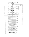
更に、本発明の第3の実施例の動作を図1(1)、(2)により説明する。図1(1)、(2)は、本発明の第3の実施例における処理プロセスの一例をフローチャートで示した図である。この図1(1)の処理プロセスは、図3で表される処理プロセスに、探索範囲拡大ループ111(ステップ111−114)を追加したものである。なお、これ以外の処理ステップはすでに説明しているため、ここでは説明は省略する。
Further, the operation of the third embodiment of the present invention will be described with reference to FIGS. FIGS. 1A and 1B are flowcharts showing an example of a processing process in the third embodiment of the present invention. The processing process of FIG. 1A is obtained by adding a search range expansion loop 111 (
図1(2)は、探索範囲拡大処理(ステップ111から114までの間の処理)の詳細を示すフローチャートである。
探索範囲拡大ループ(ステップ111−114)は、図10(3)で示されるフレーム間差分による差分画像の投影範囲である探索領域1003bを段階的に(例えば、この例では5段階に)拡大する。本実施例では、1処理フレームにつき、探索範囲拡大処理(ステップ111から114まで)を複数回、例えば、5回繰り返す。上記第2の実施例では、探索範囲dをd=50として実行しているが、本実施例では、探索範囲拡大処理、即ち、探索ステップ111からステップ114までの処理を最初に実行する場合には、探索範囲dの初期値をd=10とする(ステップ111a)。次いで、2回目の探索範囲拡大処理ではステップ114aにおいて、d+10を新たなd(即ちd=20)とし、3回目の探索範囲拡大処理では同様にステップ114aでdを更新してd=30とし、段階的に探索範囲を拡大し、5回目の探索範囲拡大処理でd=50の探索範囲となるようにすることで、探索範囲を段階的に拡大することができる。なお、探索範囲拡大処理はステップ114bにより5回を超えないようにする。
FIG. 1 (2) is a flowchart showing details of the search range expansion process (process between
The search range expansion loop (
なお、ステップ111から114の間のステップを5回繰り返す間に、差分量判定ステップ113によって所定値以上の差分が検出された場合、探索範囲拡大処理の繰り返しを中断し、侵入物体位置修正ステップ115を実行するように構成している。
If a difference greater than or equal to a predetermined value is detected by the difference
第2の実施例では、侵入物体の探索範囲内に複数の動く物体が存在する場合、差分が最も多い(差分量判定ステップ113の判定結果による)部分に侵入物体が存在するものとして無条件に侵入物体の位置を決定してしまう。それに対して、この第3の実施例のように処理プロセスを構成することで、テンプレートマッチングによって検出された侵入物体の位置を基準に、その位置に近く、差分が多く存在する場所を侵入物体の位置として決定できるため、侵入物体の探索範囲内に複数の動く物体が存在する場合でも、正しい侵入物体の位置を検出することができるようになる。この効果を図12によって説明する。 In the second embodiment, when there are a plurality of moving objects within the search range of the intruding object, it is unconditionally assumed that the intruding object exists in the portion with the largest difference (according to the determination result of the difference amount determination step 113). The position of the intruding object is determined. On the other hand, by configuring the processing process as in the third embodiment, the location of the intruding object is located near the position and there are many differences based on the position of the intruding object detected by template matching. Since the position can be determined, the correct position of the intruding object can be detected even when there are a plurality of moving objects within the intruding object search range. This effect will be described with reference to FIG.
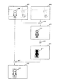
図12は、本発明の第3の実施例における侵入物体位置の検出方法を説明するための図で、ある時刻におけるフレーム間差分を適用した場合の差分画像1201を表している。図12は、侵入物体1202を追尾している途中で別の物体1203が監視視野内に現れた瞬間の画像を表している。矩形1204はテンプレートマッチングステップ106によって検出された侵入物体位置を表している。また、矩形1204a、1204b、1204c、1204d、1204eは、それぞれ、探索範囲を段階的に拡大した場合の各段階での探索範囲である。
FIG. 12 is a diagram for explaining a method of detecting an intruding object position in the third embodiment of the present invention, and shows a
この場合において、本発明の第2の実施例によれば、矩形1204eの範囲で差分が最も多い部分を検出するため、侵入物体位置修正ステップ115によって追尾中の侵入物体1202ではなく、差分量の多い別の物体1203の位置に補正してしまう。従って、追尾中の侵入物体1202ではなく、誤った別の物体1203を追尾してしまう。それに対して、本発明の第3の実施例によれば、テンプレートマッチングにより見つけた侵入物体位置1204を、例えば、2回拡大した段階での探索範囲1204bの時点で侵入物体1202を捉えることができる。即ち、最初の探索範囲1204aでは差分が所定値に達しないため、次の拡大された探索範囲1204bで探索を行う。すると、この探索範囲1204bでは差分が所定値に達するため追尾中の正しい侵入物体1202を捉えることができ、該物体1202の正しい位置を検出しそれに修正できる。
In this case, according to the second embodiment of the present invention, in order to detect the portion having the largest difference in the range of the
なお、本実施例では、探索範囲を表すX軸、Y軸方向それぞれの画素数dを1回目の探索ではd=10、2回目の探索ではd=20と段階的に大きくしているが、探索範囲の設定方法はこれに限らない。即ち、他の探索範囲の設定方法としては、例えば、探索範囲の大きさをテンプレートの大きさに固定し、テンプレートマッチングステップ106で検出した位置1204を基準に、例えば、上方向に10画素移動後の探索範囲で探索し、次に上方向に10画素かつ左方向に10画素移動後の探索範囲で探索し、次に左方向に10画素移動後の探索範囲で探索し、次に下方向に10画素かつ左方向に10画素移動後の探索範囲で探索し、次に下方向に10画素移動後の探索範囲で探索し、次に下方向に10画素かつ右方向に10画素移動後の探索範囲で探索し、次に右方向に10画素移動後の探索範囲で探索し、次に上方向に10画素かつ右方向に10画素移動後の探索範囲で探索し、次に上方向に20画素移動後の探索範囲で探索し、次に上方向に20画素かつ左方向に20画素移動後の探索範囲で探索し、次に左方向に20画素移動後の探索範囲で探索し…、というように螺旋状に探索範囲を移動しながら差分の累積値が最大となる範囲或いは差分の累積値が所定値以上となる範囲を検出するようにしても良い。 In this embodiment, the number of pixels d in the X-axis and Y-axis directions representing the search range is increased stepwise as d = 10 in the first search and d = 20 in the second search. The search range setting method is not limited to this. That is, as another setting method of the search range, for example, the size of the search range is fixed to the size of the template, and for example, after 10 pixels are moved upward with reference to the position 1204 detected in the template matching step 106 Search in the search range, and then search in the search range after moving 10 pixels in the upward direction and 10 pixels in the left direction, then search in the search range after moving 10 pixels in the left direction, and then in the downward direction Search in the search range after moving 10 pixels to the left and 10 pixels, then search in the search range after moving 10 pixels in the downward direction, then search after moving 10 pixels in the downward direction and 10 pixels in the right direction Search in the range, then search in the search range after moving 10 pixels in the right direction, then search in the search range after moving 10 pixels in the upward direction and 10 pixels in the right direction, and then 20 pixels in the upward direction Search within the search range after moving, then up Search in the search range after moving 20 pixels in the left direction and 20 pixels in the left direction, then search in the search range after moving 20 pixels in the left direction, and so on. You may make it detect the range from which a cumulative value becomes the maximum, or the range from which the cumulative value of a difference becomes more than predetermined value.
従って、侵入物体の探索範囲内に複数の動く物体が存在する場合でも、正しい侵入物体の位置を検出することができるようになるのである。以上のような結果、侵入物体追尾処理の性能を向上させることができ、信頼性の高い監視システムが容易に構築できる。 Therefore, even when there are a plurality of moving objects within the search range of the intruding object, the correct position of the intruding object can be detected. As a result, the performance of the intruding object tracking process can be improved, and a highly reliable monitoring system can be easily constructed.
なお、上記の各実施例では、侵入物体を検出し追跡する場合を例に挙げて説明したが、検出対象としては、種々なものが用いられてもよく、例えば、侵入物体以外の移動物体であっても良い。また、上記の実施例では、本発明を監視システムに適用した例を説明したが「監視」を目的としない単に移動物体を検出して追跡するシステムなどに適用してもよい。その場合にも上記実施例と同様の効果が得られる。 In each of the above embodiments, the case where an intruding object is detected and tracked has been described as an example. However, various detection targets may be used, for example, a moving object other than an intruding object. There may be. In the above embodiment, the example in which the present invention is applied to the monitoring system has been described. However, the present invention may be applied to a system that simply detects and tracks a moving object that is not intended for “monitoring”. In that case, the same effect as in the above embodiment can be obtained.
また、本発明においては、第1の実施例に第3実施例の探索範囲拡大処理を適用するようにしても良い。
また、本発明の適用分野としては、必ずしも以上に示したものに限られず、本発明は、種々な分野に適用することが可能なものである。
In the present invention, the search range expansion process of the third embodiment may be applied to the first embodiment.
The application field of the present invention is not necessarily limited to the above-described fields, and the present invention can be applied to various fields.
また、本発明に係る物体追尾装置などにおいて行われる各種の処理としては、例えばプロセッサやメモリ等を備えたハードウエア資源においてプロセッサがROM(Read Only Memory)に格納された制御プログラムを実行することにより制御される構成が用いられてもよく、また、例えば当該処理を実行するための各機能手段が独立したハードウエア回路として構成されてもよい。 Further, as various kinds of processing performed in the object tracking device according to the present invention, for example, the processor executes a control program stored in a ROM (Read Only Memory) in hardware resources including a processor and a memory. A controlled configuration may be used, and for example, each functional unit for executing the processing may be configured as an independent hardware circuit.
また、本発明は上記の制御プログラムを格納したフロッピー(登録商標)ディスクやCD(Compact Disc)−ROMやDVD(Digital Versatile Disk)−ROM等のコンピュータにより読み取り可能な記録媒体や当該プログラム(自体)として把握することもでき、当該制御プログラムを記録媒体からコンピュータに入力してプロセッサに実行させることにより、本発明に係る処理を遂行させることができる。 The present invention also relates to a computer-readable recording medium such as a floppy (registered trademark) disk, a CD (Compact Disc) -ROM, a DVD (Digital Versatile Disk) -ROM, etc., which stores the above control program, and the program itself. The processing according to the present invention can be performed by inputting the control program from a recording medium to a computer and causing the processor to execute the control program.
101:初期化処理ステップ、102:侵入物体検出処理ステップ、102a:画像入力ステップ、102b:差分処理ステップ、102c:二値化処理ステップ、102d:ラベリング処理ステップ、102e:侵入物体存在判定ステップ、103:警報・モニタ表示ステップ、104:テンプレート登録ステップ、105:画像入力ステップ、106:テンプレートマッチングステップ、107:一致度判定ステップ、108:侵入物体位置補正ステップ、109:カメラ雲台停止判定ステップ、110:フレーム間差分処理ステップ、111:探索範囲拡大ループ(開始)、112:差分量最大位置探索ステップ、113:差分量判定ステップ、114:探索範囲拡大ループ(終了)、115:侵入物体位置修正ステップ、116:侵入物体停止判定ステップ、117:テンプレート更新ステップ、118:カメラ雲台制御ステップ、119:警報・モニタ表示ステップ、201:差分量判定ステップ、401:撮像装置、401a:カメラ、401b:ズームレンズ、401c:カメラ雲台、402:処理装置、402a:画像入力部、402b:雲台制御部、402c:レンズ制御部、402d:操作入力部、402e:画像メモリ、402f:MPU、403g:ワークメモリ、402h:外部入出力部、402i:画像出力部、402j:警報出力部、402k:データバス、403:操作手段、403a:ジョイスティック、403b,403c:ボタン、404:外部記憶装置、405:出力モニタ、406:警告灯。
101: initialization processing step, 102: intruding object detection processing step, 102a: image input step, 102b: difference processing step, 102c: binarization processing step, 102d: labeling processing step, 102e: intruding object presence determination step, 103 : Alarm / monitor display step, 104: template registration step, 105: image input step, 106: template matching step, 107: matching degree determination step, 108: intruding object position correction step, 109: camera head stop determination step, 110 : Difference processing step between frames, 111: search range expansion loop (start), 112: difference amount maximum position search step, 113: difference amount determination step, 114: search range expansion loop (end), 115: intruding object position correction step 116: Invasion Object stop determination step, 117: template update step, 118: camera pan head control step, 119: alarm / monitor display step, 201: difference amount determination step, 401: imaging device, 401a: camera, 401b: zoom lens, 401c: Camera head, 402: processing device, 402a: image input unit, 402b: pan head control unit, 402c: lens control unit, 402d: operation input unit, 402e: image memory, 402f: MPU, 403g: work memory, 402h: External input / output unit, 402i: Image output unit, 402j: Alarm output unit, 402k: Data bus, 403: Operating means, 403a: Joystick, 403b, 403c: Button, 404: External storage device, 405: Output monitor, 406: Warning light.
Claims (8)
撮像装置から取得した画像から前記移動物体の一部を含むテンプレート画像を作成するテンプレート画像作成ステップと、
テンプレート画像に基づいてテンプレートマッチングを行い、マッチング位置を移動物体の位置として検出するテンプレートマッチングステップと、
撮像装置から異なる時刻に取得した2フレーム以上の画像に基づいて、フレーム間での画像の変化領域を検出する変化領域検出ステップと、
検出された画像の変化領域に基づいて移動物体の位置を検出し、該検出された移動物体の位置をテンプレートマッチングステップにより検出された移動物体の位置に代えて新たな移動物体の位置とする物体位置修正ステップと、
前記新たな移動物体の位置に対応する撮像装置から取得した画像の部分画像を新たなテンプレート画像とするテンプレート画像更新ステップとを備えることを特徴とする物体追尾方法。 In an object tracking method for detecting and tracking a moving object in a captured image based on an image obtained from an imaging device,
A template image creating step for creating a template image including a part of the moving object from an image acquired from an imaging device;
A template matching step for performing template matching based on the template image and detecting the matching position as the position of the moving object;
A change area detection step for detecting a change area of an image between frames based on images of two or more frames acquired at different times from the imaging device;
Detecting the position of the moving object on the basis of the change region of the detected image, the position of the new moving object by changing the position of the moving object issued該検the position of the moving object detected by the template matching step object A position correction step;
And a template image updating step in which a partial image of an image acquired from an imaging device corresponding to the position of the new moving object is used as a new template image.
前記物体位置修正ステップは、検出された画像の変化領域に基づいて最も多い差分或いは所定値以上の差分が検出された領域を移動物体の位置として検出することを特徴とする物体追尾方法。 The object tracking method according to claim 1,
The object position correcting step detects an area where the largest difference or a difference greater than or equal to a predetermined value is detected based on the detected change area of the image as the position of the moving object.
前記物体位置修正ステップは、テンプレートマッチングステップにより検出された移動物体の位置に基づき移動物体の位置を検出するための探索範囲を設定し、設定された探索範囲において最も多い差分或いは所定値以上の差分が検出された領域を移動物体の位置として検出することを特徴とする物体追尾方法。 The object tracking method according to claim 1,
In the object position correcting step, a search range for detecting the position of the moving object is set based on the position of the moving object detected in the template matching step, and the largest difference or a difference greater than a predetermined value in the set search range. An object tracking method characterized by detecting an area in which a point is detected as a position of a moving object.
前記探索範囲を段階的に拡大または移動し、段階的に拡大または移動している間に、所定値以上の差分が検出された場合は、当該差分が検出された領域を移動物体の位置として検出し、それ以上は拡大または移動は行わない、ことを特徴とする物体追尾方法。 The object tracking method according to claim 3,
When a difference greater than or equal to a predetermined value is detected while the search range is expanded or moved stepwise and is expanded or moved stepwise, the region where the difference is detected is detected as the position of the moving object. The object tracking method is characterized in that no further enlargement or movement is performed .
画像を予め決めた手順で処理する処理部を備え、
前記処理部は、撮像装置から取得した画像から前記移動物体の一部を含むテンプレート画像を作成し、テンプレート画像に基づいてテンプレートマッチングを行い、マッチング位置を移動物体の位置として検出し、撮像装置から異なる時刻に取得した2フレーム以上の画像に基づいて、フレーム間での画像の変化領域を検出し、検出された画像の変化領域に基づいて移動物体の位置を検出し、該検出された移動物体の位置をテンプレートマッチングにより検出された移動物体の位置に代えて新たな移動物体の位置とし、該新たな移動物体の位置に対応する撮像装置から取得した画像の部分画像を新たなテンプレート画像とすることを特徴とする物体追尾装置。 In an object tracking device that detects and tracks a moving object in a captured image based on an image obtained from the imaging device,
A processing unit for processing images in a predetermined procedure is provided.
The processing unit creates a template image including a part of the moving object from the image acquired from the imaging device, performs template matching based on the template image, detects the matching position as the position of the moving object, and based on two frames or more images acquired at different times to detect a change in area of the image between frames, and detects the position of the moving object on the basis of the change region of the detected image, the moving object issued該検Is replaced with the position of the moving object detected by the template matching, and the position of the new moving object is set, and the partial image of the image acquired from the imaging device corresponding to the position of the new moving object is set as the new template image. An object tracking device characterized by that.
前記処理部は、検出された画像の変化領域に基づいて最も多い差分或いは所定値以上の差分が検出された領域を移動物体の位置として検出することを特徴とする物体追尾装置。 The object tracking device according to claim 5, wherein
The processing unit detects an area where the largest difference or a difference greater than or equal to a predetermined value is detected as the position of a moving object based on the detected change area of the image.
前記処理部は、テンプレートマッチングにより検出された移動物体の位置に基づき移動物体の位置を検出するための探索範囲を設定し、設定された探索範囲において最も多い差分或いは所定値以上の差分が検出された領域を移動物体の位置として検出することを特徴とする物体追尾装置。 The object tracking device according to claim 5, wherein
The processing unit sets a search range for detecting the position of the moving object based on the position of the moving object detected by template matching, and the largest difference or a difference greater than a predetermined value is detected in the set search range. Tracking apparatus characterized in that the detected area is detected as the position of a moving object.
前記探索範囲を段階的に拡大または移動し、段階的に拡大または移動している間に、所定値以上の差分が検出された場合は、当該差分が検出された領域を移動物体の位置として検出し、それ以上は拡大または移動は行わない、ことを特徴とする物体追尾装置。 The object tracking device according to claim 7,
When a difference greater than or equal to a predetermined value is detected while the search range is expanded or moved stepwise and is expanded or moved stepwise, the region where the difference is detected is detected as the position of the moving object. An object tracking device characterized in that no further enlargement or movement is performed .
Priority Applications (1)
| Application Number | Priority Date | Filing Date | Title |
|---|---|---|---|
| JP2003422254A JP3973623B2 (en) | 2002-12-19 | 2003-12-19 | Object tracking method and object tracking device |
Applications Claiming Priority (2)
| Application Number | Priority Date | Filing Date | Title |
|---|---|---|---|
| JP2002367852 | 2002-12-19 | ||
| JP2003422254A JP3973623B2 (en) | 2002-12-19 | 2003-12-19 | Object tracking method and object tracking device |
Publications (3)
| Publication Number | Publication Date |
|---|---|
| JP2004213648A JP2004213648A (en) | 2004-07-29 |
| JP2004213648A5 JP2004213648A5 (en) | 2005-05-26 |
| JP3973623B2 true JP3973623B2 (en) | 2007-09-12 |
Family
ID=32828793
Family Applications (1)
| Application Number | Title | Priority Date | Filing Date |
|---|---|---|---|
| JP2003422254A Expired - Fee Related JP3973623B2 (en) | 2002-12-19 | 2003-12-19 | Object tracking method and object tracking device |
Country Status (1)
| Country | Link |
|---|---|
| JP (1) | JP3973623B2 (en) |
Families Citing this family (11)
| Publication number | Priority date | Publication date | Assignee | Title |
|---|---|---|---|---|
| JP2006267220A (en) * | 2005-03-22 | 2006-10-05 | Fujinon Corp | Auto focus system |
| JP2006267221A (en) * | 2005-03-22 | 2006-10-05 | Fujinon Corp | Auto focus system |
| JP2006258943A (en) * | 2005-03-15 | 2006-09-28 | Fujinon Corp | Autofocus system |
| JP5578816B2 (en) * | 2009-09-02 | 2014-08-27 | キヤノン株式会社 | Image processing device |
| JP5789937B2 (en) * | 2010-09-14 | 2015-10-07 | 株式会社ニコン | Image tracking device and imaging device |
| JP5461597B2 (en) * | 2012-01-30 | 2014-04-02 | 日本電信電話株式会社 | Moving object tracking method and computer program |
| CN104718562B (en) * | 2012-10-17 | 2018-07-06 | 富士通株式会社 | Image processing apparatus and image processing method |
| JP6212400B2 (en) * | 2014-01-29 | 2017-10-11 | セコム株式会社 | Object detection sensor and program |
| JP5990229B2 (en) * | 2014-08-19 | 2016-09-07 | 株式会社岩崎電機製作所 | Position change detection device |
| US9721350B2 (en) * | 2015-06-26 | 2017-08-01 | Getalert Ltd. | Methods circuits devices systems and associated computer executable code for video feed processing |
| CN112184750A (en) * | 2019-06-13 | 2021-01-05 | 北京四维图新科技股份有限公司 | Object tracking method and device based on video image |
-
2003
- 2003-12-19 JP JP2003422254A patent/JP3973623B2/en not_active Expired - Fee Related
Also Published As
| Publication number | Publication date |
|---|---|
| JP2004213648A (en) | 2004-07-29 |
Similar Documents
| Publication | Publication Date | Title |
|---|---|---|
| US7596240B2 (en) | Object tracking method and object tracking apparatus | |
| KR102126513B1 (en) | Apparatus and method for determining the pose of the camera | |
| KR100676232B1 (en) | Object tracking method, object tracking apparatus and computer-readable record medium with recorded object tracking program | |
| JP3768073B2 (en) | Object tracking method and object tracking apparatus | |
| US6687386B1 (en) | Object tracking method and object tracking apparatus | |
| JP4241742B2 (en) | Automatic tracking device and automatic tracking method | |
| KR101071352B1 (en) | Apparatus and method for tracking object based on PTZ camera using coordinate map | |
| JP3973623B2 (en) | Object tracking method and object tracking device | |
| US10083513B2 (en) | Information presentation device, stereo camera system, and information presentation method | |
| JP3644668B2 (en) | Image monitoring device | |
| JP2006229322A (en) | Automatic tracking controller and automatic tracking control method, program, and automatic tracking system | |
| JP2008009849A (en) | Person tracking device | |
| KR20140055159A (en) | Apparatus and method for detecting obstacle for around view monitoring system | |
| JP4578864B2 (en) | Automatic tracking device and automatic tracking method | |
| JP2016152027A (en) | Image processing device, image processing method and program | |
| JP5155110B2 (en) | Monitoring device | |
| JP2007274543A (en) | Image processing apparatus and method, program, and recording medium | |
| JP3560326B2 (en) | Object tracking method and object tracking device | |
| JP4699056B2 (en) | Automatic tracking device and automatic tracking method | |
| CN110378183B (en) | Image analysis device, image analysis method, and recording medium | |
| JP2006311099A (en) | Device and method for automatic tracking | |
| JP4444746B2 (en) | Object tracking method and object tracking device | |
| JP3828096B2 (en) | Object tracking device | |
| JP4302801B2 (en) | Object tracking method and object tracking apparatus | |
| TWI476735B (en) | Abnormal classification detection method for a video camera and a monitering host with video image abnormal detection |
Legal Events
| Date | Code | Title | Description |
|---|---|---|---|
| A521 | Request for written amendment filed |
Free format text: JAPANESE INTERMEDIATE CODE: A523 Effective date: 20040826 |
|
| A621 | Written request for application examination |
Free format text: JAPANESE INTERMEDIATE CODE: A621 Effective date: 20040826 |
|
| A131 | Notification of reasons for refusal |
Free format text: JAPANESE INTERMEDIATE CODE: A131 Effective date: 20061003 |
|
| A521 | Request for written amendment filed |
Free format text: JAPANESE INTERMEDIATE CODE: A523 Effective date: 20061201 |
|
| A131 | Notification of reasons for refusal |
Free format text: JAPANESE INTERMEDIATE CODE: A131 Effective date: 20070105 |
|
| A521 | Request for written amendment filed |
Free format text: JAPANESE INTERMEDIATE CODE: A523 Effective date: 20070305 |
|
| A131 | Notification of reasons for refusal |
Free format text: JAPANESE INTERMEDIATE CODE: A131 Effective date: 20070327 |
|
| A521 | Request for written amendment filed |
Free format text: JAPANESE INTERMEDIATE CODE: A523 Effective date: 20070516 |
|
| TRDD | Decision of grant or rejection written | ||
| A01 | Written decision to grant a patent or to grant a registration (utility model) |
Free format text: JAPANESE INTERMEDIATE CODE: A01 Effective date: 20070612 |
|
| A61 | First payment of annual fees (during grant procedure) |
Free format text: JAPANESE INTERMEDIATE CODE: A61 Effective date: 20070612 |
|
| R150 | Certificate of patent or registration of utility model |
Ref document number: 3973623 Country of ref document: JP Free format text: JAPANESE INTERMEDIATE CODE: R150 Free format text: JAPANESE INTERMEDIATE CODE: R150 |
|
| FPAY | Renewal fee payment (event date is renewal date of database) |
Free format text: PAYMENT UNTIL: 20100622 Year of fee payment: 3 |
|
| FPAY | Renewal fee payment (event date is renewal date of database) |
Free format text: PAYMENT UNTIL: 20110622 Year of fee payment: 4 |
|
| FPAY | Renewal fee payment (event date is renewal date of database) |
Free format text: PAYMENT UNTIL: 20120622 Year of fee payment: 5 |
|
| FPAY | Renewal fee payment (event date is renewal date of database) |
Free format text: PAYMENT UNTIL: 20130622 Year of fee payment: 6 |
|
| FPAY | Renewal fee payment (event date is renewal date of database) |
Free format text: PAYMENT UNTIL: 20140622 Year of fee payment: 7 |
|
| R250 | Receipt of annual fees |
Free format text: JAPANESE INTERMEDIATE CODE: R250 |
|
| R250 | Receipt of annual fees |
Free format text: JAPANESE INTERMEDIATE CODE: R250 |
|
| R250 | Receipt of annual fees |
Free format text: JAPANESE INTERMEDIATE CODE: R250 |
|
| LAPS | Cancellation because of no payment of annual fees |