JP3973339B2 - Method for treating tube outer surface and tube end cap used in this method - Google Patents
Method for treating tube outer surface and tube end cap used in this method Download PDFInfo
- Publication number
- JP3973339B2 JP3973339B2 JP2000042093A JP2000042093A JP3973339B2 JP 3973339 B2 JP3973339 B2 JP 3973339B2 JP 2000042093 A JP2000042093 A JP 2000042093A JP 2000042093 A JP2000042093 A JP 2000042093A JP 3973339 B2 JP3973339 B2 JP 3973339B2
- Authority
- JP
- Japan
- Prior art keywords
- tube
- cap
- port
- fitted
- receiving port
- Prior art date
- Legal status (The legal status is an assumption and is not a legal conclusion. Google has not performed a legal analysis and makes no representation as to the accuracy of the status listed.)
- Expired - Lifetime
Links
Images


Landscapes
- Protection Of Pipes Against Damage, Friction, And Corrosion (AREA)
Description
【0001】
【発明の属する技術分野】
本発明は管外面の処理方法およびこの方法に用いられる管端部キャップに関する。
【0002】
【従来の技術】
たとえばダクタイル鋳鉄によって管を鋳造した場合には、この管の外面に軽金属を溶射することによって保護膜を形成することが行われている。そして、このような溶射処理の前段階として、管の外面にショットブラスト処理を施して錆とりなどが行われている。
【0003】
このようなショットブラスト処理を行うための装置として、たとえば特開昭61−244463号公報には、一方の管の受口の内部に他方の管の挿口を挿入して、これら管どうしを連続させるとともにその軸心方向に送りを付与しながら、ショットブラスト処理を行うようにしたものが記載されている。
【0004】
【発明が解決しようとする課題】
このようなものであると、複数の管に連続的に処理を行うことができる利点があるが、一方の管の受口に挿入した他方の管の挿口の部分にはショットブラスト処理を施すことが困難である。また、受口の内面とこの受口に挿入される挿口の外面との間には隙間が存在し、この隙間を介して管の内部にショット粒が入り込むため、このショット粒を取り除くための後工程が必要になる。
【0005】
そこで本発明は、挿口の先端までショットブラスト処理を行えるようにするとともに、管内にショット粒が入り込まないようにすることを目的とする。
【0006】
【課題を解決するための手段】
この目的を達成するため本発明は、一端に受口を有するとともに他端に挿口を有した管の外面にショットブラスト処理を施すに際し、第1の管の受口にはめ込まれるキャップであって、前記第1の管の受口の内周に押し込み状態ではめ込まれる筒部と、この筒部の先端に連続してこの筒部と一体に形成された底部と、第1の管の受口に掛かり合う掛かり合い部と、第2の管の挿口を外側に被せることができる環状突部と、この環状突部の基端部に設けられて、第2の管の挿口の先端面が接することで、この挿口をその最先端まで露出させた状態で、この挿口の先端を塞ぐことができる端面と、第1の管にはめ込まれるときのガイドとなる先端の外周テーパ面とを有したキャップにより、第1の管の受口と第2の管の挿口の先端とを塞いで、第1の管と第2の管とを軸心方向に連続させかつ第2の管の挿口の先端を第1の管の受口と同心に支持させた状態で、ショットブラスト処理を施すものである。
【0007】
このようにすると、挿口はキャップによってその先端が塞がれるだけであり、受口の内部に入り込むことがないため、この挿口の先端までショットブラスト処理を施すことが可能となる。また第1の管の受口にはめ込まれるキャップによりこの第1の管の受口と第2の管の挿口の先端とが塞がれるため、これら第1および第2の管の内部にショット粒が入り込むことが防止される。
【0008】
また本発明は、一端に受口を有するとともに他端に挿口を有する管の外面をショットブラスト処理するときに用いるキャップが、第1の管の受口にはめ込まれることが可能に構成され、前記キャップは、前記第1の管の受口の内周に押し込み状態ではめ込まれる筒部と、この筒部の先端に連続してこの筒部と一体に形成された底部と、第1の管の受口に掛かり合う掛かり合い部と、第2の管の挿口を外側に被せることができる環状突部と、この環状突部の基端部に設けられて、第2の管の挿口の先端面が接することで、この挿口をその最先端まで露出させた状態で、この挿口の先端を塞ぐことができる端面と、第1の管にはめ込まれるときのガイドとなる先端の外周テーパ面とを有して、第1の管の受口にはめ込まれたときに、第1の管と第2の管とを軸心方向に連続させかつ第2の管の挿口の先端を第1の管の受口と同心に支持させた状態で、第1の管の受口と第2の管の挿口の先端とを塞ぐことができるように構成されているようにしたものである。
【0009】
このようなものであると、挿口はキャップによってその先端が塞がれるだけであり、受口の内部に入り込むことがないため、この挿口の先端まで外面の処理を施すことができる。また、第1の管の受口にはめ込まれるキャップにより、第2の管の挿口を第1の管の受口と同心に支持した状態で、この第1の管の受口と第2の管の挿口の先端とが塞がれるため、このキャップを管の外面のショットブラスト処理に供した場合は、これら第1および第2の管の内部にショット粒が入り込むことが防止される。
【0010】
【発明の実施の形態】
図2は、鋳鉄管にショットブラストおよび溶射を行うための設備の概略構成を示す。この図2において、1は管の外面に溶射処理を行うための装置、2はその溶射処理の前段階としてショットブラスト処理を行うための装置である。3は処理対象としての鋳鉄管で、その一端に接合用の受口4を有するとともに、その他端に、管どうしの接合時に他の管3の受口4の内部に挿入される挿口5を有する。
【0011】
このような構成において、管3にショットブラストと溶射とを施す際には、図示のようにある管3の受口4に他の管3の挿口5を連結させて、複数の管3、3、…を互いに水平な軸心方向に連続させた状態で、これらの管3、3、…を、ショットブラスト処理を行うための装置2に通したうえで溶射処理を行うための装置1に通して、連続的な処理を行うようにされている。装置1における溶射処理が終了した管3は、互いの連結状態が解除されて、一本ずつ、たとえばその軸心と直交する水平方向に搬送される。6は、その直交方向への搬送路を示す。
【0012】
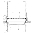
このようにショットブラストと溶射とを施すために管3、3、…どうしを連結させる場合に、図1に示されるようなキャップ7が用いられる。このキャップ7は、耐摩耗性ゴムなどによって図示のような有底筒状体にて構成され、管3の受口4の開口に押し込み状態ではめ込まれるように構成されている。また、このようにしてある管3の受口4の開口に装着されたキャップ7には、他の管3の挿口5の先端がはめ合わされるように構成され、これによってこれらの管3、3どうしが軸心方向に連結されるように構成されている。
【0013】
図3は、キャップ7の詳細構造を示す。このキャップ7において、8は受口の内部への挿入部で、一方の管3の受口4の内周に押し込み状態ではめ込まれる筒部9と、この筒部9の先端に連続する底部10とを一体に有した構成とされている。筒部9の先端には、この筒部9を受口4の内部にはめ込むときのガイドとなる外周テーパ面11が形成されている。またキャップ7には、受口4に軸心方向に掛かり合う掛かり合い部13が形成されている。この掛かり合い部13が受口に掛かり合うことで、受口4の内部への挿入部8の入り込み量が適正になるように規制される。
【0014】
キャップ7における受口4から外方へ突出した部分12には、挿口4を外側に被せることができる環状突部17が形成されている。またキャップ7には環状突部17の基端部において端面18が形成されており、この端面18に挿口5の先端面が接することで、この挿口5の先端が塞がれることになる。
【0015】
挿入部8が一方の管3の受口4に挿入されたキャップ7は、他方の管3の挿口5が環状突部17にはめ合わされることで、挿口5を受口4に対して同心状態で支持することが可能である。
【0016】
そしてキャップ7は、このようにして受口4と挿口5とをシール状態かつ同心状態で相互に連結させることが可能であり、この連結状態で受口4の開口端と挿口5の開口端とを塞ぐことができるように構成されている。このとき、挿口5はその最先端の外周まで露出し、したがって完全にショットブラスト処理を施すことができる利点がある。
【0017】
このような構成において、管3、3の外面にショットブラスト処理および溶射処理を施す際には、図1および図3に示すようにキャップ7を用いて管3、3どうしを同心状態で互いに連結し、この連結状態の管3、3を図2に示すショットブラスト装置2および溶射装置1に送り込んで、所定の処理を行う。
【0018】
このとき、上述のように各管3、3の受口4および挿口5はいずれもキャップ7によって一緒に塞がれているため、ショットブラスト装置2において管3、3の内部にショット粒が入り込むことが確実に防止される。また、挿口5はキャップ7によってその先端面の部分が塞がれるだけであり、その最先端の外周まで露出するため、その最先端まで外面にショットブラスト処理およびそれに続く溶射処理を施すことができる。
【0019】
しかも、キッャプ7によって一方の管3の受口4に対し他方の管3の挿口5が同心状態に支持されるため、互いに軸心方向に連結された複数の管3、3を何ら支障なくショットブラスト装置2に送り込むことができる。
【0020】
このようにキャップ7よって互いに連結された複数の管3、3にショットブラストと溶射とが施された後に、各管3は図2に示すように搬送路6に沿って軸心と直交する水平方向に搬送され、この搬送路6における適宜の位置で用済み後のキャップ7が取り外される。
【0021】
なお、キャップ7は、上述のように管3、3の外面にショットブラスト処理と溶射処理とを施す場合に使用できるほかに、管3、3の外面に他の処理を施す際にも使用することができる。
【0022】
【発明の効果】
以上のように本発明によると、第1の管の受口にはめ込まれるキャップであって、前記第1の管の受口の内周に押し込み状態ではめ込まれる筒部と、この筒部の先端に連続してこの筒部と一体に形成された底部と、第1の管の受口に掛かり合う掛かり合い部と、第2の管の挿口を外側に被せることができる環状突部と、この環状突部の基端部に設けられて、第2の管の挿口の先端面が接することで、この挿口をその最先端まで露出させた状態で、この挿口の先端を塞ぐことができる端面と、第1の管にはめ込まれるときのガイドとなる先端の外周テーパ面とを有したキャップにより、第1の管の受口と第2の管の挿口の先端とを塞いで、第1の管と第2の管とを軸心方向に連続させかつ第2の管の挿口の先端を第1の管の受口と同心に支持させた状態で、ショットブラスト処理を施すため、挿口はキャップによってその先端面の部分が塞がれるだけであり、受口の内部に入り込むことがないため、この挿口の最先端までショットブラスト処理を施すことができる。また第1の管の受口にはめ込まれるキャップによりこの第1の管の受口と第2の管の挿口の先端とが塞がれるため、これら第1および第2の管の内部にショット粒が入り込むことを確実に防止できる。
【0023】
また本発明によると、一端に受口を有するとともに他端に挿口を有する管の外面をショットブラスト処理するときに用いるキャップが、第1の管の受口にはめ込まれることが可能に構成され、前記キャップは、前記第1の管の受口の内周に押し込み状態ではめ込まれる筒部と、この筒部の先端に連続してこの筒部と一体に形成された底部と、第1の管の受口に掛かり合う掛かり合い部と、第2の管の挿口を外側に被せることができる環状突部と、この環状突部の基端部に設けられて、第2の管の挿口の先端面が接することで、この挿口をその最先端まで露出させた状態で、この挿口の先端を塞ぐことができる端面と、第1の管にはめ込まれるときのガイドとなる先端の外周テーパ面とを有して、第1の管の受口にはめ込まれたときに、第1の管と第2の管とを軸心方向に連続させかつ第2の管の挿口の先端を第1の管の受口と同心に支持させた状態で、第1の管の受口と第2の管の挿口の先端とを塞ぐことができるように構成されているため、挿口はキャップによってその先端面の部分が塞がれるだけであり、受口の内部に入り込むことがないため、この挿口の最先端まで外面の処理を施すことができる。また、第1の管の受口にはめ込まれるキャップにより、第2の管の挿口を第1の管の受口と同心に支持した状態で、この第1の管の受口と第2の管の挿口の先端とが塞がれるため、これら第1および第2の管の内部にショット粒が入り込むことを確実に防止できる。
【図面の簡単な説明】
【図1】 本発明の実施の形態のキャップを用いて管どうしを連結した状態を示す図である。
【図2】 キャップを装着した管の処理工程を説明するための図である。
【図3】 キャップの詳細構造を示す断面図である。
【符号の説明】
3 鋳鉄管
4 受口
5 挿口
7 キャップ
8 挿入部
12 突出部分[0001]
BACKGROUND OF THE INVENTION
The present invention relates to a method for treating a tube outer surface and a tube end cap used in the method.
[0002]
[Prior art]
For example, when a pipe is cast with ductile cast iron, a protective film is formed by spraying light metal on the outer surface of the pipe. And as a pre-stage of such a thermal spraying process, the outer surface of the pipe is subjected to shot blasting to remove rust and the like.
[0003]
As an apparatus for performing such shot blasting, for example, in Japanese Patent Application Laid-Open No. 61-244463, an insertion port of the other tube is inserted into the receiving port of one tube, and these tubes are continuously connected. And shot blasting is performed while feeding in the axial direction.
[0004]
[Problems to be solved by the invention]
Such a configuration has an advantage that processing can be continuously performed on a plurality of tubes, but shot blasting is performed on the insertion portion of the other tube inserted into the receiving port of one tube. Is difficult. In addition, there is a gap between the inner surface of the receiving port and the outer surface of the insertion port inserted into the receiving port, and shot particles enter the inside of the tube through this gap, so that this shot particle is removed. A post process is required.
[0005]
Accordingly, an object of the present invention is to enable shot blasting to the tip of the insertion opening and prevent shot grains from entering the tube.
[0006]
[Means for Solving the Problems]
In order to achieve this object, the present invention provides a cap that is fitted into the receiving port of the first tube when performing shot blasting on the outer surface of the tube having a receiving port at one end and an insertion port at the other end. A cylindrical portion that is fitted in the inner periphery of the receiving opening of the first tube in a pressed state; a bottom portion that is formed integrally with the cylindrical portion continuously from the tip of the cylindrical portion; and a receiving port for the first tube An engaging portion that engages with each other, an annular protrusion that can cover the insertion opening of the second tube, and a distal end surface of the insertion opening of the second tube that is provided at the base end portion of the annular protrusion The end face that can close the distal end of the insertion opening with the insertion opening exposed to the forefront, and an outer peripheral tapered surface that serves as a guide when fitted into the first tube. The cap having the first tube and the tip of the second tube insertion opening are closed, The shot blasting process is performed in a state where the tube and the second tube are continuous in the axial direction and the tip of the insertion opening of the second tube is supported concentrically with the receiving port of the first tube. .
[0007]
If it does in this way, since the front-end | tip of an insertion port will only be obstruct | occluded with a cap and will not enter the inside of a receiving port, it will become possible to perform a shot blast process to the front-end | tip of this insertion port. Further, the cap fitted into the first tube receptacle closes the first tube receptacle and the second tube insertion tip, so that shots are made inside these first and second tubes. Grain is prevented from entering.
[0008]
Further, the present invention is configured such that a cap used when shot blasting the outer surface of a tube having a receiving port at one end and an insertion port at the other end can be fitted into the receiving port of the first tube, The cap includes a cylindrical portion that is fitted in the inner periphery of the receiving opening of the first tube in a pressed state, a bottom portion that is formed integrally with the cylindrical portion continuously from a distal end of the cylindrical portion, and a first tube An engaging portion that engages with the receiving port, an annular protrusion that can cover the insertion opening of the second tube, and an insertion opening of the second tube that is provided at the base end of the annular protrusion. The end surface of the insertion port is in contact with the leading end of the insertion port so that the insertion port is exposed to the forefront, and the outer periphery of the distal end that serves as a guide when fitted into the first tube. The first pipe and the first pipe when the first pipe is fitted into the receptacle of the first pipe. In the axial direction and with the distal end of the insertion opening of the second tube being supported concentrically with the receiving port of the first tube, the receiving port of the first tube and the second tube It is configured to be able to close the tip of the insertion hole.
[0009]
If it is such, since the front-end | tip of an insertion port is only block | closed with a cap and does not enter the inside of a receiving port, the process of an outer surface can be given to the front-end | tip of this insertion port. In addition, with the cap fitted into the first tube receiving port, the insertion port of the second tube is supported concentrically with the receiving port of the first tube. Since the tip of the insertion opening of the tube is blocked, when this cap is subjected to shot blasting on the outer surface of the tube, shot particles are prevented from entering the first and second tubes.
[0010]
DETAILED DESCRIPTION OF THE INVENTION
FIG. 2 shows a schematic configuration of equipment for performing shot blasting and thermal spraying on a cast iron pipe. In FIG. 2, 1 is an apparatus for performing a thermal spraying process on the outer surface of a pipe, and 2 is an apparatus for performing a shot blasting process as a pre-stage of the thermal spraying process.
[0011]
In such a configuration, when shot blasting and thermal spraying are performed on the
[0012]
In order to connect the
[0013]
FIG. 3 shows the detailed structure of the
[0014]
An
[0015]
The
[0016]
The
[0017]
In such a configuration, when shot blasting and thermal spraying are performed on the outer surfaces of the
[0018]
At this time, since the receiving
[0019]
Moreover, since the
[0020]
After shot blasting and thermal spraying are performed on the plurality of
[0021]
The
[0022]
【The invention's effect】
As described above, according to the present invention, the cap is fitted into the receiving opening of the first tube, and is fitted into the inner periphery of the receiving opening of the first tube in the pressed state, and the tip of the tubular portion A bottom portion formed integrally with the cylindrical portion, an engaging portion that engages with the receiving opening of the first tube, an annular protrusion that can cover the insertion opening of the second tube, Provided at the base end of the annular projection, the tip of the insertion port of the second tube is in contact with the tip of the insertion tube so that the tip of the insertion port is exposed to the forefront. The end of the first tube and the distal end of the insertion port of the second tube are closed by a cap having an end surface that can be fitted and an outer peripheral tapered surface that serves as a guide when fitted into the first tube. The first tube and the second tube are continuous in the axial direction, and the distal end of the insertion opening of the second tube is supported concentrically with the receiving port of the first tube. In order to perform shot blasting, the insertion port is only clogged with the cap at the tip, and does not enter the interior of the insertion port. Can be applied. Further, the cap fitted into the first tube receptacle closes the first tube receptacle and the second tube insertion tip, so that shots are made inside these first and second tubes. It is possible to reliably prevent the grains from entering.
[0023]
Further, according to the present invention, the cap used when shot blasting the outer surface of a pipe having a receiving port at one end and an insertion port at the other end can be fitted into the receiving port of the first pipe. , said cap, said a cylindrical portion to be fitted in a state pushed into the inner periphery of the receptacle of the first tube, and continuous from the leading end of the cylindrical portion and a bottom portion formed integrally with the cylindrical portion, the first An engaging portion that engages with the receiving port of the tube, an annular protrusion that can cover the insertion opening of the second tube on the outside, and a base end portion of the annular protruding portion. With the end surface of the mouth in contact, the end surface that can close the distal end of the insertion port with the insertion port exposed to the forefront, and the distal end that serves as a guide when fitted into the first tube An outer peripheral taper surface, and when fitted into the first tube receptacle, the first And the second tube in the axial direction and the tip of the second tube insertion port is supported concentrically with the first tube receiving port and the second tube receiving port and the second tube. Because it is configured to be able to block the tip of the tube's insertion port, the insertion port is only blocked by the cap at the tip surface, and does not enter the interior of the receiving port, The outer surface can be treated up to the forefront of this insertion. In addition, with the cap fitted into the first tube receiving port, the insertion port of the second tube is supported concentrically with the receiving port of the first tube. Since the tip of the tube insertion opening is closed, it is possible to reliably prevent shot grains from entering the first and second tubes.
[Brief description of the drawings]
FIG. 1 is a view showing a state in which tubes are connected using a cap according to an embodiment of the present invention.
FIG. 2 is a view for explaining a processing step of a pipe fitted with a cap.
FIG. 3 is a cross-sectional view showing a detailed structure of a cap.
[Explanation of symbols]
3
Claims (2)
Priority Applications (1)
| Application Number | Priority Date | Filing Date | Title |
|---|---|---|---|
| JP2000042093A JP3973339B2 (en) | 2000-02-21 | 2000-02-21 | Method for treating tube outer surface and tube end cap used in this method |
Applications Claiming Priority (1)
| Application Number | Priority Date | Filing Date | Title |
|---|---|---|---|
| JP2000042093A JP3973339B2 (en) | 2000-02-21 | 2000-02-21 | Method for treating tube outer surface and tube end cap used in this method |
Publications (2)
| Publication Number | Publication Date |
|---|---|
| JP2001232567A JP2001232567A (en) | 2001-08-28 |
| JP3973339B2 true JP3973339B2 (en) | 2007-09-12 |
Family
ID=18565211
Family Applications (1)
| Application Number | Title | Priority Date | Filing Date |
|---|---|---|---|
| JP2000042093A Expired - Lifetime JP3973339B2 (en) | 2000-02-21 | 2000-02-21 | Method for treating tube outer surface and tube end cap used in this method |
Country Status (1)
| Country | Link |
|---|---|
| JP (1) | JP3973339B2 (en) |
Families Citing this family (1)
| Publication number | Priority date | Publication date | Assignee | Title |
|---|---|---|---|---|
| CN117140369A (en) * | 2023-09-06 | 2023-12-01 | 新兴铸管股份有限公司 | Ductile iron pipe outer wall shot blasting device and method |
-
2000
- 2000-02-21 JP JP2000042093A patent/JP3973339B2/en not_active Expired - Lifetime
Also Published As
| Publication number | Publication date |
|---|---|
| JP2001232567A (en) | 2001-08-28 |
Similar Documents
| Publication | Publication Date | Title |
|---|---|---|
| US5366260A (en) | Plastic pipe coupler | |
| EP1323488A3 (en) | Electrode for welding | |
| KR920010995A (en) | Quick Connector | |
| JP3973339B2 (en) | Method for treating tube outer surface and tube end cap used in this method | |
| US11220887B1 (en) | Method and apparatus for cleaning and inspecting oil well drilling mud flow lines | |
| CA2473145C (en) | Method for cleaning the tubes of a heat exchanger using an abrasive and a device suitable for the method | |
| WO2004110134A3 (en) | Fluid handling assemblies | |
| US11181730B2 (en) | Endoscope leak test connector, endoscope leak tester and endoscope reprocessor | |
| EP0814202A3 (en) | Drainage system | |
| JPH05154694A (en) | Gas shielding tools for welding | |
| JPH0847678A (en) | Method and hose brush for cleaning powder conduit of powder spray coating device | |
| KR920703867A (en) | Metal tube oxidation treatment equipment | |
| KR20130050347A (en) | Jet-receiving nozzle for a powder-delivery injector plus powder-delivery injector | |
| CN219620266U (en) | Novel upper smoke tube for smoking machine | |
| KR0173078B1 (en) | Inert gas filling method and apparatus for metal pipe welding | |
| JP2009511931A (en) | FUEL COVER PROTECTION COLOR, METHOD FOR PRODUCING FUEL SOD, AND DEVICE FOR PERFORMING THE METHOD | |
| FR2727042A1 (en) | RIVET FEEDING DEVICE | |
| JP2897713B2 (en) | Apparatus and method for purging pipe material like pipe coil | |
| JPS59118279A (en) | Welder | |
| JPS6139683Y2 (en) | ||
| JP2605111Y2 (en) | Corrosion protection core for fittings | |
| JPS58155836A (en) | Apparatus for connecting liquid sending tube in endoscope | |
| JPH09184582A (en) | Forming method of the projection of the tube opening | |
| JP3525925B2 (en) | Pipe fittings | |
| JP2002340257A (en) | Insertion opening insert fitting in pipe joint |
Legal Events
| Date | Code | Title | Description |
|---|---|---|---|
| A621 | Written request for application examination |
Free format text: JAPANESE INTERMEDIATE CODE: A621 Effective date: 20040427 |
|
| A977 | Report on retrieval |
Free format text: JAPANESE INTERMEDIATE CODE: A971007 Effective date: 20060526 |
|
| A131 | Notification of reasons for refusal |
Free format text: JAPANESE INTERMEDIATE CODE: A131 Effective date: 20060620 |
|
| A521 | Written amendment |
Free format text: JAPANESE INTERMEDIATE CODE: A523 Effective date: 20060821 |
|
| A131 | Notification of reasons for refusal |
Free format text: JAPANESE INTERMEDIATE CODE: A131 Effective date: 20070220 |
|
| A521 | Written amendment |
Free format text: JAPANESE INTERMEDIATE CODE: A523 Effective date: 20070418 |
|
| TRDD | Decision of grant or rejection written | ||
| A01 | Written decision to grant a patent or to grant a registration (utility model) |
Free format text: JAPANESE INTERMEDIATE CODE: A01 Effective date: 20070515 |
|
| A61 | First payment of annual fees (during grant procedure) |
Free format text: JAPANESE INTERMEDIATE CODE: A61 Effective date: 20070612 |
|
| R150 | Certificate of patent or registration of utility model |
Ref document number: 3973339 Country of ref document: JP Free format text: JAPANESE INTERMEDIATE CODE: R150 Free format text: JAPANESE INTERMEDIATE CODE: R150 |
|
| FPAY | Renewal fee payment (event date is renewal date of database) |
Free format text: PAYMENT UNTIL: 20100622 Year of fee payment: 3 |
|
| FPAY | Renewal fee payment (event date is renewal date of database) |
Free format text: PAYMENT UNTIL: 20100622 Year of fee payment: 3 |
|
| FPAY | Renewal fee payment (event date is renewal date of database) |
Free format text: PAYMENT UNTIL: 20110622 Year of fee payment: 4 |
|
| FPAY | Renewal fee payment (event date is renewal date of database) |
Free format text: PAYMENT UNTIL: 20120622 Year of fee payment: 5 |
|
| FPAY | Renewal fee payment (event date is renewal date of database) |
Free format text: PAYMENT UNTIL: 20130622 Year of fee payment: 6 |
|
| FPAY | Renewal fee payment (event date is renewal date of database) |
Free format text: PAYMENT UNTIL: 20140622 Year of fee payment: 7 |
|
| EXPY | Cancellation because of completion of term |