JP3973301B2 - Cylindrical grinding wheel polishing equipment - Google Patents
Cylindrical grinding wheel polishing equipment Download PDFInfo
- Publication number
- JP3973301B2 JP3973301B2 JP26893498A JP26893498A JP3973301B2 JP 3973301 B2 JP3973301 B2 JP 3973301B2 JP 26893498 A JP26893498 A JP 26893498A JP 26893498 A JP26893498 A JP 26893498A JP 3973301 B2 JP3973301 B2 JP 3973301B2
- Authority
- JP
- Japan
- Prior art keywords
- cylindrical body
- polishing
- driving side
- counter
- drive
- Prior art date
- Legal status (The legal status is an assumption and is not a legal conclusion. Google has not performed a legal analysis and makes no representation as to the accuracy of the status listed.)
- Expired - Fee Related
Links
- 238000005498 polishing Methods 0.000 title claims description 215
- 230000033001 locomotion Effects 0.000 claims description 20
- 238000003825 pressing Methods 0.000 claims description 9
- XLYOFNOQVPJJNP-UHFFFAOYSA-N water Substances O XLYOFNOQVPJJNP-UHFFFAOYSA-N 0.000 description 9
- 238000004140 cleaning Methods 0.000 description 7
- 239000000314 lubricant Substances 0.000 description 7
- 239000011295 pitch Substances 0.000 description 7
- 244000145845 chattering Species 0.000 description 3
- 239000007788 liquid Substances 0.000 description 3
- 238000013459 approach Methods 0.000 description 2
- 239000000428 dust Substances 0.000 description 2
- 238000005259 measurement Methods 0.000 description 2
- 238000000034 method Methods 0.000 description 2
- 238000007747 plating Methods 0.000 description 2
- 239000007921 spray Substances 0.000 description 2
- 239000004575 stone Substances 0.000 description 2
- RYGMFSIKBFXOCR-UHFFFAOYSA-N Copper Chemical compound [Cu] RYGMFSIKBFXOCR-UHFFFAOYSA-N 0.000 description 1
- 230000005540 biological transmission Effects 0.000 description 1
- 239000003795 chemical substances by application Substances 0.000 description 1
- 229910052802 copper Inorganic materials 0.000 description 1
- 239000010949 copper Substances 0.000 description 1
- 230000007547 defect Effects 0.000 description 1
- 230000000694 effects Effects 0.000 description 1
- 239000012530 fluid Substances 0.000 description 1
- 230000006870 function Effects 0.000 description 1
- 238000009434 installation Methods 0.000 description 1
- 230000009545 invasion Effects 0.000 description 1
- 238000003754 machining Methods 0.000 description 1
- 238000007494 plate polishing Methods 0.000 description 1
- 238000005096 rolling process Methods 0.000 description 1
- 239000002893 slag Substances 0.000 description 1
- 239000008399 tap water Substances 0.000 description 1
- 235000020679 tap water Nutrition 0.000 description 1
- 238000005406 washing Methods 0.000 description 1
Images

Landscapes
- Constituent Portions Of Griding Lathes, Driving, Sensing And Control (AREA)
- Grinding Of Cylindrical And Plane Surfaces (AREA)
Description
【0001】
【発明の属する技術分野】
本願発明は、対向する一対又は二対の研磨ヘッドを有して円筒体に対して両側より研磨できることにより研磨代が大きい研磨をビビリが生じることなく実現でき、また円筒体をチャックする一方の反駆動側チャック手段を支持する反駆動側ブラケットを円筒体の面長方向に移動・案内する機構が、潤滑剤や洗浄水が垂れない配置であるとともに、上方から円筒体のハンドリングができ、また円筒体の研磨代を必要最小限に抑えて研磨することができて円筒体の一端から他端まで高精密に均一な直径に研磨できる円筒体の砥石研磨装置に関する。
【0002】
【従来の技術】
従来、研磨ヘッドを複数有している円筒体の砥石研磨装置は、
人手により研磨作業を行うことが前提であったので、円筒体回転手段によりチャックされる円筒体の一側に研磨ヘッドが二つ又は三つ並んでいるタイプであった。
また、上記従来の円筒体の砥石研磨装置は、反駆動側チャック手段が両端チャックされる円筒体の下方に、二条のガイドレールが敷設されガイドレール間にモータにより回転されるボールネジがあり、二条のガイドレールに係合案内される四つのリニアブロックに固定された可動テーブルにボールネジと螺合するボールナットが固定され、これらを長尺なカバーが覆い、カバーの上側に位置し反駆動側チャック手段を支持する可動ブラケットの下部両端がカバーの幅方向両端の下側の隙間を介して可動テーブルに固定されている。
【0003】
【発明が解決しようとする課題】
上記従来の円筒体の砥石研磨装置は、円筒体の固有振動数と研磨圧力が合致するとビビリが生じる不具合がある。このビビリを解消する方法を種々試したところ、50Kg位の押圧力を反研磨側より円筒体の長さ中央に加えてやると円筒体の固有振動数に共鳴しないことが分かった。
また上記従来の円筒体の砥石研磨装置は、潤滑剤や洗浄水がカバーの幅方向両端の下側の隙間を介して侵入しカバーで覆われたガイドレールやボールネジに大量に付着し研磨によって生じる粉塵が大量に堆積し、ガイドレールやボールネジ等を早期に錆させる欠点があった。
また、円筒体が印刷ロールである場合、印刷ロールの中程の直径が両端部の直径よりも大きいか小さいと、印刷が行われないので、印刷ロールは極めて高い円筒精度が要求される。また、圧延ロールでも更に高い円筒精度が要求される。
しかるに、砥石研磨装置で円筒体の円筒研磨を行うと、研磨砥石の表面が漸次に崩壊していくので、その分について補正をかけて円筒研磨を行うことで円筒精度を出すようになっている。
しかし、円筒研磨する前の円筒体の円筒精度が低い場合、上記従来の補正をかけた円筒研磨を行っても円筒精度が高くなるとは限らない。高い円筒精度を有する砥石研磨装置で補正をかけて大きな研磨代をとって一回で円筒体の一端から他端まで円筒研磨すると、円筒研磨する前の円筒体の円筒精度がそのまま反映した円筒研磨精度しか得られない。円筒研磨する前の円筒体の円筒精度が低くても、高い円筒精度を得るには、極めて高い円筒精度を有する砥石研磨装置を使用しかつ研磨砥石の表面が漸次に崩壊していく分について補正をかけて極めて微小な研磨代となるように円筒研磨を行うことを何回も反復して円筒体の中程と両端部の直径の差を解消していく必要があった。そして、円筒研磨後は円筒体を取外し測定器に載置して円筒精度を測定する必要があり、もしも、円筒精度が出ていないときは、円筒体を再び精密円筒研磨して再び円筒精度を測定することを反復していたので、大変煩雑であるとともに時間がかかっていた。また、円筒研磨を反復すると、円筒体の直径が小さくなり過ぎる惧れがあった。
【0004】
本願発明は、上述した点に鑑み案出したもので、対向する一対又は二対の研磨ヘッドを有して円筒体に対して両側より研磨できることにより研磨代が大きい研磨をビビリが生じることなく実現でき、また円筒体をチャックする一方の反駆動側チャック手段を支持する反駆動側ブラケットを円筒体の面長方向に移動・案内する機構が、潤滑剤や洗浄水が垂れない配置であるとともに、上方から円筒体のハンドリングができ、また円筒体の研磨代を必要最小限に抑えて研磨することができて円筒体の一端から他端まで高精密に均一な直径に研磨できる円筒体の砥石研磨装置を提供するものである。
【0005】
【課題を解決するための手段】
本願第一の発明は、駆動側スピンドルの対向端に設けられ水平に位置させる円筒体の一端をチャックする駆動側チャック手段と、反駆動側スピンドルの対向端に設けられ前記円筒体の他端をチャックする反駆動側チャック手段と、フレームの後面部の上方部位より前記駆動側スピンドルの方向に張り出していて前記駆動側スピンドルを軸支する駆動側ブラケットと、フレームの後面部の上方部位または前記駆動側ブラケットに取りつけられ前記駆動側スピンドルを回転駆動する円筒体回転用モータと、フレームの後面部の円筒体よりも上方部位において前記円筒体に沿って直動案内手段に係合案内され前記反駆動側スピンドルの方向に張り出していて前記反駆動側スピンドルを軸支する反駆動側ブラケットと、前記円筒体の下側において円筒体の面長方向に移動自在な単一又は二つのXテーブル上に設けられた円筒体の水平直径方向に移動自在な一対又は二対のYテーブルに設けられ、研磨砥石を砥石回転用モータにより回転し研磨砥石の端面を一定の押圧力で円筒体に押圧して研磨しうる一対又は二対の研磨ヘッド装置とからなり、前記二つのXテーブルを前記円筒体の面長方向に対して両側に設けかつ前記一対又は二対のYテーブルを前記円筒体の面長方向に対して両側に設けることを特徴とする円筒体の砥石研磨装置を提供するものである。
【0006】
本願第二の発明は、本願第一の発明において、駆動側スピンドルの対向端に設けられ水平に位置させる円筒体の一端をチャックする駆動側チャック手段と、反駆動側スピンドルの対向端に設けられ前記円筒体の他端をチャックする反駆動側チャック手段と、フレームの後面部の上方部位より前記駆動側スピンドルの方向に張り出していて前記駆動側スピンドルを軸支する駆動側ブラケットと、フレームの後面部の上方部位または前記駆動側ブラケットに取りつけられ前記駆動側スピンドルを回転駆動する円筒体回転用モータと、フレームの後面部の円筒体よりも上方部位において前記円筒体に沿って直動案内手段に係合案内され前記反駆動側スピンドルの方向に張り出していて前記反駆動側スピンドルを軸支する反駆動側ブラケットと、前記円筒体の下側において円筒体の面長方向に移動自在な単一又は二つのXテーブル上に設けられた円筒体の水平直径方向に移動自在な一対又は二対のYテーブルに設けられ、研磨砥石を砥石回転用モータにより回転し研磨砥石の端面を一定の押圧力で円筒体に押圧して研磨しうる一対又は二対の研磨ヘッド装置とからなり、制御回路に入力される、研磨しようとする円筒体の一端から他端まで細かい一定ピッチで直径値を予め測定した直径値データに対応して、該制御回路が、最小の直径値データと、これよりも大きい直径値データとの差値を円筒体の研磨代として、該研磨代部分に対応して研磨砥石が所要の往復移動を行うように、前記Xテーブルを円筒体の面長方向に移動自在とするXテーブル移動用モータを正逆回転制御するように構成されていることを特徴とする円筒体の砥石研磨装置を提供するものである。
【0007】
【発明の実施の形態】
本願発明の実施の形態に係る円筒体の砥石研磨装置を説明する。
この実施の形態の円筒体の砥石研磨装置は、
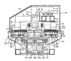
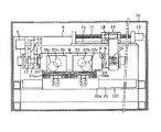
図1ないし図3に示すように、駆動側スピンドル1の対向端に設けられた截頭円錐形の駆動側チャック手段2と反駆動側スピンドル3の対向端に設けられた截頭円錐形の反駆動側チャック手段4とで円筒体Wの両端の円錐形の被チャック孔をチャックするようになっている。駆動側スピンドル1及び反駆動側スピンドル3の外側にはキャップ5又は6を備えていて、円筒体Wのチャックが行われると、圧力流体によってチャック方向にストロークされ円筒体Wの端面に当接して駆動側スピンドル1又は反駆動側スピンドル3を一体回転可能に密閉し、もって、研磨の塵埃、研磨剤、洗浄水の侵入を防止するようになっている。
【0008】
駆動側ブラケット7は、「L」字を90度右回転した様に水平に張り出してから垂下するL字ブラケットであり、基端をフレーム8の後面部の駆動側スピンドル1に対応する上方部位に固定され、張り出し側下部にて駆動側スピンドル1を軸支している。円筒体回転用モータ9は、フレーム8の上方部(又は駆動側ブラケット7)に取りつけられていて、タイミング歯車10、タイミングベルト11、タイミング歯車12を介して駆動側スピンドル1を回転駆動する。
【0009】
反駆動側ブラケット13は、駆動側ブラケット7と同様のL字ブラケットであり、基端をフレーム8の後面部の円筒体Wに対応する上方部位に設けられた反駆動側ブラケット用ガイド14、14に係合案内されていて、反駆動側スピンドル3を一定ストローク移動自在に軸支している。反駆動側スピンドル3は、強力なコイルばね15によりチャック方向に寄った位置に付勢移動されている。チャック用モータ16はサーボモータが使用されボールネジ17を回転するように連結され、該ボールネジ17に螺合するボールナット18は反駆動側ブラケット13に固定されている。
円筒体Wのチャックは、図示しない産業用ロボットにより円筒体Wを水平に支持し一方の被チャック孔を駆動側チャック手段2に嵌合してから、チャック用モータ16を予めデータ入力された円筒体Wの長さに対応する回転数だけ回転し、図示しないブレーキ装置により回転不能にロックされる。すると、反駆動側ブラケット13がボールネジ17とボールナット18の螺合によりチャック方向に移動し、反駆動側チャック手段4が円筒体Wの他方の被チャック孔に嵌合する。反駆動側チャック手段4を支持する反駆動側スピンドル3は、強力なコイルばね15を圧縮してスライドする。従って、円筒体Wをチャックする駆動側チャック手段2と反駆動側チャック手段4のチャック力は、コイルばね15の付勢力である。コイルばね15の付勢力が小さいと、研磨時にビビリが容易に発生するので、強力なコイルばね15が必要である、
なお、コイルばね15の付勢を利用しない場合は、高出力のトルクモータを使用するか、モータを廃して高出力にシリンダ装置を採用する。
【0010】
駆動側ブラケット7と反駆動側ブラケット13をフレーム8の後面部の上方部位よりL字形に張り出して、駆動側スピンドル1と反駆動側スピンドル3を軸支する構造としたのは、反駆動側ブラケット13を円筒体Wの面長方向に移動・案内する機構を、潤滑剤や洗浄水が垂れない配置にするとともに、図示しない産業用ロボットにより上方から円筒体Wのハンドリングができるようにするためである。
【0011】
駆動側チャック手段2と反駆動側チャック手段4により水平にチャックされる円筒体Wの両側には四つの研磨ヘッド装置19、20、21、22を備えていて、いずれか一つ乃至四つ研磨ヘッド装置は、円筒体Wに対し種々のバリエーションで研磨することができる。
【0012】
四つの研磨ヘッド装置19、20、21、22は、オートツールチャック機能を有する構造(詳細はマシニングセンタ等で公知なので図示しない)の研磨回転軸19a、20a、21a、又は22aに軸部を固定チャックされた研磨砥石19b、20b、21b、又は22bを備え、かつ、研磨回転軸19a、20a、21a、又は22aが砥石回転用モータ19c、20c、21c、又は22cにより回転されるようになっている。研磨砥石19bと20bが端面を円筒物Wに向けて一軸線上に対向し、また研磨砥石21bと22bが端面を円筒物Wに向けて一軸線上に対向している。
【0013】
四つの研磨ヘッド装置19、20、21、22の装置本体は、Yテーブル装置23、24、25、又は26のYテーブル23a、24a、25a、又は26aにリニアガイド27、27とリニアブロック28、28を介して載置されているとともに、Xテーブル31aに設けた各別のYテーブル用モータ(サーボモータ)23b、24b、25b、又は26bを駆動源としてYテーブル移動用ボールネジ29とYテーブル移動用ボールナット30を介して円筒体Wに対する接近・離隔移動に関して個別移動自在である。
Yテーブル移動用モータ23b、24b、25b、又は26bはYテーブル移動用ボールネジ29を回転し、Yテーブル移動用ボールネジ29に螺合するYテーブル移動用ボールナット30はYテーブルに対して回転不能にかつ防震ゴム31を介してYテーブルに弾持されている。
Yテーブル移動用モータ23b、24b、25b、又は26bは、対応する研磨砥石が円筒体Wに近接するまでは一定回転数を前記Yテーブル移動用ボールネジに与えてYテーブル23a、24a、25a、又は26aを早送りし、対応する研磨砥石が円筒体Wに近接した後は引続き同方向に遅速回転して研磨砥石を円筒体Wに当接して常に一定トルクをYテーブル移動用ボールネジ29に与えることにより、研磨砥石を円筒体Wに一定圧力で押圧するようになっている。
円筒体Wは、真円ではなく振れ回り回転する。このため、一側における円筒面の迫り出しと後退の寸法は、被製版ロールにあっては最大で約60μmとなる。これに対応してYテーブル23a、24a、25a、26aは、微小寸法で往復動して追随する必要があるとともに、研磨砥石を円筒体Wに一定圧力で押圧する必要がある。防震ゴム31は、Yテーブル23a、24a、25a、26aの微小寸法の追随往復動を可能にしているとともに、円筒体Wの振れ回り回転によって生起する押圧反力の変動を緩和してYテーブル移動用ボールネジ29にトルク反力の変動となる伝達を遮断する役目を果たしている。もって、Yテーブル移動用モータ23b、24b、25b、26bは、安定した一定トルクを出力するようになっている。
【0014】
Xテーブル装置32は、Xテーブル32aがリニアガイド32bとリニアブロック32c並びにリニアガイド32dとリニアブロック32eを介して基台32fに載置されているとともに、フレーム8に設けたXテーブル用モータ(サーボモータ)32gを駆動源としてボールネジ32hとボールナットランナ32iを介して円筒体Wの面長方向に沿って移動自在である。
Xテーブル32aは、円筒体Wの面長方向に最大長さの円筒体Wの両端よりも外方へ移動自在である。
【0015】
従って、四つの研磨ヘッド装置19、20、21、22は、円筒体Wに対する接近・離隔移動に関して、対応するYテーブルの移動に伴い個別に移動するとともに、円筒体Wの面長方向の移動に関して、Xテーブル32aの移動に伴い、一体的に移動するようになっている。
【0016】
Yテーブル装置23、24、25、26とXテーブル装置32は、円筒体Wよりも下方にあるので、Yテーブル装置23、24、25、26の直動・案内構造部分をカバー33、34で覆い、またXテーブル装置32の直動・案内構造部分をカバー35で覆っていて、潤滑剤や洗浄水の流入を防止するようになっている。
【0017】
扉36は、ケーシング37の正面側の側面から上面にわたる円筒体出し入れ用開口を遮蔽し、円筒体出し入れ時には水平移動して開放するように設けられている。扉36の天井部には、下向きの噴射ノズルを小寸法ピッチ毎に有する三本の給液管38、39、40が扉36と一体的に移動可能に設けられ、研磨時は、給液管38、40の噴射ノズルより研磨用潤滑液(中水)を円筒体Wの全長両側面に噴射するようになっており、また、研磨修了後は、給液管39の噴射ノズルより洗浄水(水道水)を円筒体Wの全長上面側に噴射するようになっている。
【0018】
制御装置41には、研磨しようとする円筒体Wの一端から他端まで一定ピッチ毎に計測した直径値、ロール長さ、被チャック孔の孔径等がデータ入力されるようになっていて、該データに基づいて、チャック用モータ16とYテーブル用モータ23b、24b、25b、26bとXテーブル用モータ32gが 制御駆動される。
また、制御装置41には、Yテーブル用モータ23b、24b、25b、26bの原点位置に対応する未使用の研磨砥石の端面位置が初期データとして入力されているとともに、研磨修了時のYテーブル用モータ23b、24b、25b、26bの原点位置からの回転角度をメモリにストアしてデータ入力されている円筒体Wの直径値と実行研磨代とから、毎回の研磨後のYテーブル用モータ23b、24b、25b、26bの原点位置に対応する研磨砥石の端面位置を記憶しておいて、次の研磨に利用するようになっている。
さらに、制御装置41には、例えば、データ入力されている各直径値の最小直径値に対する差を研磨代として320番の研磨砥石19aによりランダムな研磨を行って円筒体Wの一端から他端までを最小直径値とし、次いで、320番の研磨砥石19a、20aにより円筒体Wの一端から他端までダブル研磨することにより研磨代の大きい落版を行い、次いで、320番の研磨砥石19a、20aの駆動源のモータの電源をオフにして円筒体Wの一端から他端まで連れ回り研磨して500番〜600番の研磨砥石による中仕上げ研磨粗さ相当の研磨を実現し、次いで、800番の研磨砥石21aにより円筒体Wの一端から他端まで中仕上げ研磨を行い、次いで、研磨砥石21aの駆動源のモータの電源をオフにして連れ回り研磨して1500番〜1600番の研磨砥石による中仕上げ研磨相当の研磨を実現し、次いで、6000番のPVA製の研磨砥石22aにより円筒体Wの一端から他端まで上仕上げ研磨を行い、次いで、研磨砥石22aの駆動源のモータの電源をオフにして連れ回り研磨して鏡面研磨を実現するソフトが選択的に格納されている。
【0019】
制御回路41は、研磨砥石19aによりランダムな研磨を行って円筒体Wの一端から他端までを最小直径値とするために、最小の直径値データと、これよりも大きい直径値データとの差値を円筒体の研磨代として、該研磨代部分に対応して研磨砥石が所要の往復移動研磨を行うように、Xテーブル32aを円筒体Wの面長方向に移動自在とするXテーブル移動用モータ32gを正逆回転制御するように構成されている。
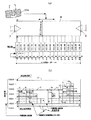
すなわち、制御回路41による直接の制御対象はXテーブル移動用モータ32gであり正逆回転制御することにあるが、究極の制御対象は研磨砥石19aであり、前記研磨代部分に対応して研磨砥石19aにより所要の往復移動研磨を行うことにある。従って、制御回路41による研磨砥石19aの往復移動制御の具体例を、図4(a)、(b)を参照して説明する。
図4(a)は、駆動側チャック手段2と反駆動側チャック手段4で両端チャックされ回転される円筒体Wを研磨砥石19aにより研磨する所を示すもので、図中の直径値は、円筒体Wの一定ピッチ毎に各区間の計測直径値を補正した研磨前直径値を示す。
図4(a)は、円筒体Wの一端から10mm離れた位置の直径を計測し、次いで30mmピッチで直径を計測し、最後の計測箇所から円筒体Wの他端まで10mm離れている所を示す。直径計測は、小数点第三位まで計測して小数点第三位を四捨五入した。
研磨砥石19aは、円筒体Wに密着し研磨圧力を一定に保って一方向へ移動するときの一回の研磨寸法が2.5ミクロンとなるように、研磨圧力が調整されて研磨を行えるようになっており、研磨砥石19aが一往復研磨すると円筒体Wは直径が10ミクロン小さくなるように研磨される。
従って、各区間の研磨前直径値の最小位は、小数点第二位であるので研磨砥石の一回の研磨寸法が2.5ミクロンであるから該一回の研磨寸法の四倍となるように値に補正されている。
図4(b)は、円筒体の各区間の研磨前直径値をブロック積みの棒グラフで示しかつブロックを取り除く順序を矢印と番号で示すことにより研磨砥石19aの移動順序によって説明するものである。図中、左の数値は直径値であり、一目盛りは5ミクロンである。従って、一つのブロックの高さは5ミクロンある。研磨砥石の一回の研磨寸法が2.5ミクロンであるので、研磨砥石19aを一往復することにより一つのブロックを取り除くことができる。
以下に、ブロックを取り除く順序の説明を通して、直径が最終的に均一になることを概念的に説明する。
ブロックが積まれたものであるならば、下段のブロックを取り除くとその上に積まれているブロックは一段下がる。実際の研磨は内部から先に行うことはできない。しかし、ある区間の研磨を最上段のブロックに対する研磨ではなく下段のブロックに対する研磨に相当するものと概念的に決めて直径を小さく研磨していく考えることができる。
しかして、研磨砥石19aを円筒体Wに密着し一回の研磨寸法が2.5ミクロンとなるように研磨圧力を一定に保って図4(b)中の矢印に付けた符号1から符号18に示す順序で往復移動を繰り返しつつ研磨することにより、一往復研磨したブロックを取り除いていくと、円筒体全長を研磨前最小直径値よりも一往復研磨した小さい均一径に研磨することができる。
研磨砥石19aの往復移動の順序を示す、図4(b)中の1から18の番号の付け方は以下の規則に従っている。研磨前最小直径値よりも大きな研磨代部分に相当するブロックは、図4(b)中の矢印に付けた符号1、2、4、6、8、10、12、14、16の順序で往復研磨を完了した順に取り除く。
従って、ブロックが研磨前直径値に比例して積まれているので、各区間の研磨前最小直径値よりも大きな研磨代部分に相当するブロックは、積まれているブロックの数だけ研磨移動を往復したときに全部取り除くことができる。
図4(b)中の例えば符号1の往復研磨を行うことで概念的に同じ段のブロックの取り除くことは、各区間の研磨代部分が連続して存在するときはその連続する区間を往復研磨することを意味している。また、図4(b)中の例えば符号2の往復研磨を行って概念的に同じ段のブロックの取り除くように連続する区間を往復研磨すると、符号4の往復区間のブロックと符号6の往復区間のブロックとに別れる。そこで、研磨砥石は、符号3の矢印区間のブロックの符号3の方向に研磨して符号4の往復研磨を行って符号4の矢印区間のブロックを取り除き、次いで、符号5の矢印区間のブロックの符号5の方向に研磨して符号6の往復研磨を行って符号6の矢印区間のブロックを取り除くようにして、研磨砥石の研磨圧力を零にしたりさらに研磨砥石を円筒体から離したりしない。
すなわち、往復研磨を少なくとも一回行ってなお存在する研磨代部分が離れるときは、既に研磨前最小直径値に研磨した区間を円筒体の一端から他端に向かって研磨移動する。さらに、図4(b)中の符号16の往復研磨を行うと、研磨前最小直径値よりも大きな研磨代部分がなくなるまで研磨したことになるので、引き続いて、符号17の方向に既に研磨前最小直径値に研磨した区間を研磨する。
もって、円筒体の全長を研磨前最小直径値よりも一方向に一回研磨した小さい均一径となるように断続して研磨したことになる。
そこで、最後に、円筒体の他端から一端に向かって図4(b)中の符号18の復動研磨を行う。これによって、円筒体の全長を研磨前最小直径値よりも一往復研磨した小さい均一径となるように研磨したことになる。
実際の研磨は内部から先に行うことは不可能であるが、上記のブロックを取り除く順序で説明するように砥石研磨の移動を行うと、円筒体の直径が小さくなる状態があり、あたかも下段のブロックを取り除くと上段のブロックが一段落ち、かつブロックが取り除かれる順 番に対応するように概念的に把握することができ、結果として、必要最小限の砥石研磨の移動により、円筒体の全長を研磨前最小直径値よりも一往復研磨した小さい均一径となるように精密研磨することができる。
なお、図4(b)中の符号18の研磨を行うことは、必要ではない。その理由は、符号17の研磨を終了した時点で均一径となるからである。
要するに、制御回路41による研磨砥石19aの往復移動制御は、円筒体Wの一端から他端まで一定ピッチ毎に計測した各区間の計測直径値の最小位について、研磨砥石19aを円筒体Wに密着し研磨圧力を一定に保って一方向へ移動するときの一回研磨寸法の四倍となるように近似する値に補正した各区間の研磨前直径値とし、研磨砥石を円筒体に密着し研磨圧力を一定に保って往復移動を繰り返しつつ研磨することにより、研磨前最小直径値よりも全長を一回研磨した小さい均一径に研磨するものであって、
研磨前最小直径値よりも大きな研磨代部分は、研磨前直径値に比例した往復回数だけ研磨し、その際各区間の研磨代部分が連続して存在するときはその連続する区間を往復研磨し、該往復研磨を少なくとも一回行ってなお存在する研磨代部分が離れるときは、既に研磨前最小直径値に研磨した区間を重複しないように研磨移動して研磨代部分に到達させて該研磨代部分を往復研磨し、研磨前最小直径値よりも大きな研磨代部分がなくなるまで研磨したら、円筒体の他端まで既に研磨前最 小直径値に研磨した残りの区間を研磨移動するものである。
【0020】
本願発明は、上記の実施の態様に限定されるものではない。
円筒体Wが軸付タイプの被製版ロールであるときは、駆動側チャック手段2と反駆動側チャック手段4は、円筒状でありロール軸に被嵌チャックするように構成される。
Xテーブル装置は、チャックされる円筒体Wの両側に別れて独立に、及び同調して作動しうるように二つ有り、円筒体Wの面長方向の移動に関して、Yテーブル装置23と25を、又、Yテーブル装置24と26をそれぞれ一体的に移動するように構成してもよい。
【0021】
【発明の効果】
本願発明の円筒体の砥石研磨装置によれば、
(1)駆動側チャック手段を支持する反駆動側ブラケットと、反駆動側チャック手段を支持する反駆動側ブラケットと、反駆動側ブラケットを円筒体の面長方向に移動する直動案内機構をフレームの後面部の上方より設けたことにより、反駆動側ブラケットの直動案内機構に潤滑剤や洗浄水が垂れなくなるとともに、チャックされる円筒体の下側の大きな空間をテーブル設置用空間として確保できて、X−Y方向に移動自在なテーブル装置を円筒体のチャック手段やチャック手段を支持するブラケットと干渉しないように装備することができ、また、ハンドリング空間をチャックする円筒体の上方に確保でき、円筒体の両側に一対又は二対の研磨砥石を対向させて方式が実現できる。
(2)対向する一対又は二対の研磨砥石により円筒体を挟んでダブル研磨できるので、研磨圧力を大きくして研磨代を大きく取って研磨しても、両側の研磨圧力が相殺するので、ビビリが生じることない短時間研磨が実現できる。従って、被製版ロール(使用済みの印刷ロール)を脱クロムメッキ処理した後の落版研磨にように円筒体の研磨代が大きい場合に好適であり、落版研磨時間の大幅な短縮化が繋がる。
(3)チャックされる円筒体の上方に、円筒体のハンドリング空間を確保できる。
(4)円筒体を研磨ヘッドを最大長さの円筒体の両端よりも面長方向外方にスライドする範囲と、最小長から最大長さまでの任意の長さの円筒体を両端チャックして回転するチャック回転手段のスライドする範囲とが重複しない構造であり、装置を構成している可動部材同士の干渉を回避した構造を実現して、ダブル研磨、ダブル・ダブル研磨が実現できる。
(5)四つの研磨ヘッド装置を備えたときは、研磨ソフトを搭載することにより、円筒体に対し種々のバリエーションで研磨することができる。例えば、四つの研磨ヘッド装置が順に選択され、粗仕上げ研磨−中仕上げ研磨−上仕上げ研磨−鏡面研磨を行ったり、二つの研磨ヘッド装置を同時に作動してダブル粗仕上げ研磨、又はダブル鏡面研磨を行ったり、粗仕上げ研磨と砥石を駆動しない連れ回り研磨を行うことができる。
(6)第二の発明にあっては、最小の直径値データと、これよりも大きい直径値データとの差値を円筒体の研磨代として、該研磨代部分に対応して研磨砥石がランダムな所要の往復移動研磨を行って円筒体の一端から他端までを最小直径値とすることができるので、円筒体の一端から他端まで高精密に均一な直径に研磨でき、研磨代を必要最小限に抑えることができ、短時間研磨が実現でき、被製版ロールの円筒研磨にあっては膜厚が小さい銅メッキで済む。
【図面の簡単な説明】
【図1】本願第一発明及び本願第二発明に共通する実施の形態にかかる円筒体の砥石研磨装置の平面図。
【図2】図1におけるII−II矢視図。
【図3】図1における III−III 矢視図。
【図4】本願発明の実施の態様にかかる円筒体の砥石研磨方法を説明するための図である。(a)は、円筒体を研磨砥石で研磨するに際して、円筒体の一定ピッチ毎の研磨前直径値を示す。(b)は、円筒体の各区間の研磨前直径値をブロック積みの棒グラフで示しかつブロックを取り除く順序を矢印と番号で示すことにより研磨砥石の移動を説明するための図である。
【符号の説明】
1 ・・・駆動側スピンドル
2 ・・・駆動側チャック手段
3 ・・・反駆動側スピンドル
4 ・・・反駆動側チャック手段
5、6 ・・・キャップ
W ・・・円筒体
7 ・・・駆動側ブラケット
8 ・・・フレーム
9 ・・・円筒体回転用モータ
10、12 ・・・タイミング歯車
11 ・・・タイミングベルト
13 ・・・反駆動側ブラケット
14 ・・・反駆動側ブラケット用ガイド
15 ・・・コイルばね
16 ・・・チャック用モータ
17 ・・・ボールネジ
18 ・・・ボールナット
19、20、21、22 ・・・研磨ヘッド装置
19a、20a、21a、22a ・・・研磨回転軸
19b、20b、21b、22b ・・・研磨砥石
19c、20c、21c、22c ・・・砥石回転用モータ
23、24、25、26 ・・・Yテーブル装置
23a、24a、25a、26a ・・・Yテーブル
27 ・・・リニアガイド
28 ・・・リニアブロック
23b、24b、25b、26b ・・・Yテーブル用モータ
29 ・・・Yテーブル移動用ボールネジ
30 ・・・Yテーブル移動用ボールナット
31 ・・・防震ゴム
32 ・・・Xテーブル装置
32a ・・・Xテーブル
32b ・・・リニアガイド
32c ・・・リニアブロック
32d ・・・リニアガイド
32e ・・・リニアブロック
32f ・・・基台
32g ・・・Xテーブル用モータ
32h ・・・ボールネジ
32i ・・・ボールナットランナ
33、34、35 ・・・カバー
36 ・・・扉
37 ・・・ケーシング
38、39、40 ・・・給液管
41 ・・・制御回路[0001]
BACKGROUND OF THE INVENTION
The present invention has a pair of facing polishing heads or two pairs of polishing heads and can polish the cylindrical body from both sides so that a large polishing allowance can be realized without chattering, and one side of chucking the cylindrical body can be realized. The mechanism that moves and guides the non-drive side bracket that supports the drive side chuck means in the surface length direction of the cylindrical body is arranged so that lubricant and cleaning water do not drip, and the cylinder body can be handled from above, and the cylinder The present invention relates to a cylindrical grindstone polishing apparatus that can polish a body with a minimum polishing cost and can grind to a uniform diameter with high precision from one end to the other end of the cylindrical body.
[0002]
[Prior art]
Conventionally, a cylindrical grindstone polishing apparatus having a plurality of polishing heads,
Since it was assumed that the polishing operation was performed manually, it was a type in which two or three polishing heads were arranged on one side of the cylindrical body chucked by the cylindrical body rotating means.
Further, the conventional grindstone polishing apparatus for a cylindrical body has a ball screw which is provided with two guide rails and is rotated by a motor between the guide rails below the cylindrical body on which the counter driving side chuck means is chucked at both ends. A ball nut that is screwed to a ball screw is fixed to a movable table fixed to four linear blocks that are engaged and guided by guide rails of the guide rail. A long cover covers these nuts, and the chuck is located on the upper side of the cover. Both ends of the lower part of the movable bracket supporting the means are fixed to the movable table via gaps below the both ends in the width direction of the cover.
[0003]
[Problems to be solved by the invention]
The conventional cylindrical grindstone polishing apparatus has a problem that chattering occurs when the natural frequency of the cylindrical body matches the polishing pressure. When various methods for eliminating this chatter were tested, it was found that when a pressing force of about 50 kg was applied to the center of the length of the cylindrical body from the anti-polishing side, it did not resonate with the natural frequency of the cylindrical body.
Further, the conventional cylindrical grindstone polishing device described above is caused by polishing, with a large amount of lubricant or cleaning water entering through the gaps at the lower ends of the cover in the width direction and adhering to the guide rail or ball screw covered with the cover. There was a defect that a large amount of dust accumulated and rusted guide rails and ball screws at an early stage.
Further, when the cylindrical body is a printing roll, printing is not performed when the diameter of the middle of the printing roll is larger or smaller than the diameter of both ends, and therefore, the printing roll is required to have extremely high cylinder accuracy. Further, even a rolling roll requires higher cylinder accuracy.
However, when the cylindrical body is polished with the grindstone polishing apparatus, the surface of the grinding wheel gradually collapses, so that the cylinder accuracy is obtained by correcting the amount and performing the cylindrical polishing. .
However, when the cylinder accuracy of the cylindrical body before the cylinder polishing is low, the cylinder accuracy is not necessarily increased even if the cylinder polishing with the above-described conventional correction is performed. When grinding is performed from one end of the cylinder body to the other end with a large grinding allowance by correcting with a grinding machine with high cylinder accuracy, the cylinder polishing reflects the cylinder accuracy of the cylinder body before it is polished. Only accuracy can be obtained. Even if the cylinder accuracy before cylindrical polishing is low, in order to obtain high cylinder accuracy, use a grindstone polishing machine with extremely high cylinder accuracy and compensate for the gradual collapse of the surface of the grinding wheel It was necessary to eliminate the difference between the diameters of the middle and both ends of the cylindrical body by repeating the cylindrical polishing many times so that a very small polishing allowance was applied. After polishing the cylinder, it is necessary to remove the cylinder and place it on a measuring instrument to measure the cylinder accuracy. If the cylinder accuracy is not achieved, the cylinder body is again subjected to precision cylinder polishing to increase the cylinder accuracy again. Repeating the measurement was very cumbersome and time consuming. In addition, when the cylindrical polishing was repeated, the diameter of the cylindrical body might be too small.
[0004]
The present invention has been devised in view of the above-described points, and has a pair of polishing heads facing each other and can polish from both sides with respect to a cylindrical body, thereby realizing polishing with a large polishing margin without causing chatter. The mechanism that moves and guides the counter driving side bracket that supports one counter driving side chuck means for chucking the cylindrical body in the surface length direction of the cylindrical body is arranged so that lubricant and cleaning water do not drip, Grinding of a cylindrical body that can handle a cylindrical body from above, and can polish the cylindrical body with a minimum grinding allowance, and can polish to a uniform diameter with high precision from one end of the cylindrical body to the other. A device is provided.
[0005]
[Means for Solving the Problems]
The first invention of the present application includes a driving side chuck means for chucking one end of a cylindrical body which is provided at the opposite end of the driving side spindle and is positioned horizontally, and the other end of the cylindrical body which is provided at the opposite end of the counter driving side spindle. A counter drive side chuck means for chucking, a drive side bracket projecting from the upper portion of the rear surface portion of the frame toward the drive side spindle and supporting the drive side spindle, and an upper portion of the rear surface portion of the frame or the drive A cylinder rotating motor that is mounted on a side bracket and rotationally drives the drive side spindle, and is engaged and guided by the linear guide means along the cylindrical body at a position above the cylindrical body on the rear surface portion of the frame, and the counter drive A non-driving side bracket that projects in the direction of the side spindle and pivotally supports the non-driving side spindle, and a cylinder below the cylindrical body. Rotating the grinding wheel by a grinding wheel rotating motor, provided on one or two pairs of Y tables movable in the horizontal diameter direction of a cylindrical body provided on one or two X tables movable in the surface length direction And a pair of polishing head devices capable of polishing by pressing the end face of the polishing grindstone against the cylindrical body with a constant pressing force. The two X tables are provided on both sides with respect to the surface length direction of the cylindrical body, and the one or two pairs of Y tables are provided on both sides with respect to the surface length direction of the cylindrical body. The present invention provides a cylindrical grindstone polishing apparatus characterized by the above.
[0006]
The second invention of the present application is the first invention of the present application, provided with a driving side chuck means for chucking one end of a cylindrical body that is provided at the opposite end of the driving side spindle and is positioned horizontally, and provided at the opposite end of the counter driving side spindle. A counter driving side chucking means for chucking the other end of the cylindrical body, a driving side bracket projecting from the upper part of the rear surface of the frame toward the driving side spindle, and supporting the driving side spindle; A cylinder rotating motor that is attached to the upper part of the surface part or the driving side bracket and rotationally drives the driving side spindle, and the linear guide means along the cylindrical body at a part above the cylindrical body of the rear surface part of the frame. A counter driving side bracket that is engaged and guided in the direction of the counter driving side spindle and pivotally supports the counter driving side spindle; Polished on one or two pairs of Y tables movable in the horizontal diameter direction of the cylindrical body provided on one or two X tables movable on the surface length direction of the cylindrical body on the lower side of the cylindrical body. It consists of a pair or two pairs of polishing head devices that can grind by rotating the grindstone by a grindstone rotating motor and pressing the end face of the grindstone against the cylindrical body with a constant pressing force. Corresponding to the diameter value data measured in advance at a fine constant pitch from one end of the cylindrical body to the other end, the control circuit calculates the minimum diameter value data and the larger diameter value data. Difference value Is used as a grinding allowance for the cylindrical body, and an X table moving motor for making the X table movable in the surface length direction of the cylindrical body so that the grinding wheel reciprocates as required corresponding to the grinding allowance portion. The present invention provides a cylindrical grindstone polishing apparatus characterized by being configured to perform reverse rotation control.
[0007]
DETAILED DESCRIPTION OF THE INVENTION
A cylindrical grindstone polishing apparatus according to an embodiment of the present invention will be described.
The cylindrical grindstone polishing apparatus of this embodiment is
As shown in FIGS. 1 to 3, the frustoconical driving side chuck means 2 provided at the opposite end of the driving
[0008]
The drive-side bracket 7 is an L-shaped bracket that hangs horizontally after extending “L” 90 ° clockwise, and has a base end at an upper portion corresponding to the drive-
[0009]
The
The chuck of the cylindrical body W is a cylinder in which data is input in advance to the
When the bias of the
[0010]
The drive side bracket 7 and the counter
[0011]
Four polishing
[0012]
The four
[0013]
The apparatus bodies of the four polishing
The Y
The Y
The cylindrical body W swings around instead of being a perfect circle. For this reason, the size of the protrusion and retreat of the cylindrical surface on one side is about 60 μm at the maximum in the plate making roll. Correspondingly, the Y tables 23a, 24a, 25a, and 26a need to reciprocate with a minute dimension and follow the grinding wheel and press the polishing grindstone against the cylindrical body W at a constant pressure. The
[0014]
In the
The X table 32a is movable outwardly from both ends of the cylindrical body W having the maximum length in the surface length direction of the cylindrical body W.
[0015]
Accordingly, the four polishing
[0016]
Since the
[0017]
The
[0018]
The
Further, the end face position of the unused grinding wheel corresponding to the origin position of the
Further, the
[0019]
The
In other words, the direct control object by the
FIG. 4A shows a place where a cylindrical body W that is chucked and rotated at both ends by the driving side chuck means 2 and the counter driving side chuck means 4 is polished by a polishing
FIG. 4 (a) measures the diameter at a
The polishing
Accordingly, since the minimum value of the diameter value before polishing in each section is the second decimal place, the polishing size of the polishing wheel is 2.5 microns, so that the polishing size is four times the polishing size. The value has been corrected.
FIG. 4B illustrates the diameter value before polishing of each section of the cylindrical body by a bar graph of block stacking and the order of removing the blocks by arrows and numbers, and is explained by the moving order of the polishing
Hereinafter, it will be conceptually explained that the diameter finally becomes uniform through the description of the order of removing the blocks.
If the blocks are stacked, removing the lower block lowers the block stacked on it. Actual polishing cannot be performed from the inside first. However, it can be considered that the polishing of a certain section is conceptually determined to correspond to the polishing of the lower block, not the polishing of the uppermost block, and the diameter is reduced.
Accordingly, the
The numbering of 1 to 18 in FIG. 4 (b) showing the order of reciprocating movement of the
Accordingly, since the blocks are stacked in proportion to the diameter value before polishing, the blocks corresponding to the polishing allowance larger than the minimum diameter value before polishing in each section reciprocate the polishing movement by the number of stacked blocks. You can remove it all.
For example, by performing reciprocal polishing indicated by
That is, when the polishing margin portion that is still present after the reciprocal polishing is performed at least once, the section that has already been polished to the minimum diameter value before polishing is polished and moved from one end of the cylindrical body to the other end. Further, when the reciprocal polishing indicated by
Accordingly, the entire length of the cylindrical body is intermittently polished so as to have a smaller uniform diameter that is polished once in one direction than the minimum diameter value before polishing.
Therefore, finally, backward polishing of
Although it is impossible to perform actual polishing first from the inside, if the grinding wheel is moved as described in the order of removing the above blocks, the diameter of the cylindrical body may be reduced. Ah As a result, if the lower block is removed, it can be conceptualized so that the upper block falls one step and corresponds to the order in which the blocks are removed. Precision polishing can be performed so that the entire length of the cylindrical body has a uniform diameter smaller than the minimum diameter before polishing by one reciprocal polishing.
In addition, it is not necessary to perform the grinding | polishing of the code |
In short, the reciprocating movement control of the
The polishing allowance larger than the minimum diameter before polishing is polished by the number of reciprocations in proportion to the diameter before polishing, and if there are consecutive polishing allowances in each section, the successive sections are polished back and forth. If the existing polishing margin part is left after the reciprocal polishing is performed at least once, the polishing margin is moved to reach the polishing margin part so as not to overlap the already polished minimum diameter value before polishing. When the part is subjected to reciprocal polishing and polished until there is no polishing allowance larger than the minimum diameter value before polishing, the remaining section which has already been polished to the minimum diameter value before polishing is moved to the other end of the cylindrical body.
[0020]
The present invention is not limited to the above embodiment.
When the cylindrical body W is a shaft-made plate making roll, the driving side chuck means 2 and the counter driving side chuck means 4 are cylindrical and are configured to be fitted and chucked to the roll shaft.
There are two X table devices so that they can be operated independently and synchronously on both sides of the cylindrical body W to be chucked, and the
[0021]
【The invention's effect】
According to the cylindrical grinding wheel polishing apparatus of the present invention,
(1) A frame that includes a counter driving side bracket that supports the driving side chuck means, a counter driving side bracket that supports the counter driving side chuck means, and a linear motion guide mechanism that moves the counter driving side bracket in the surface length direction of the cylindrical body. By providing it from above the rear surface, the lubricant and cleaning water do not drip on the linear guide mechanism of the non-drive side bracket, and a large space below the cylinder to be chucked can be secured as a table installation space. Thus, a table device movable in the XY directions can be installed so as not to interfere with the cylindrical chuck means and the bracket supporting the chuck means, and the handling space can be secured above the cylindrical body to be chucked. The system can be realized by making one or two pairs of grinding wheels face each other on both sides of the cylindrical body.
(2) Since double polishing can be performed with a cylindrical body sandwiched between a pair or two pairs of polishing stones facing each other, even if polishing is performed with a large polishing pressure and a large polishing allowance, the polishing pressure on both sides cancels. Polishing can be realized for a short time without occurrence of slag. Therefore, it is suitable for the case where the polishing cost of the cylindrical body is large as in the case of the falling plate polishing after the plate making roll (used printing roll) is subjected to the dechrome plating treatment, and the time for polishing the falling plate is greatly shortened. .
(3) A handling space for the cylindrical body can be secured above the cylindrical body to be chucked.
(4) Rotate the cylindrical body by chucking both ends of the cylindrical body of any length from the minimum length to the maximum length and the range in which the polishing head slides outward in the surface length direction from both ends of the cylindrical body of the maximum length The structure in which the chuck rotating means does not overlap with the sliding range, and a structure that avoids interference between the movable members constituting the apparatus can be realized to realize double polishing and double / double polishing.
(5) When four polishing head devices are provided, the cylindrical body can be polished in various variations by mounting polishing software. For example, four polishing head devices are selected in order, and rough finishing polishing, intermediate finishing polishing, top finishing polishing, mirror polishing, or two polishing head devices are operated simultaneously to perform double rough finishing polishing or double mirror polishing. It is possible to perform rough polishing and follow-up polishing without driving a grindstone.
(6) In the second invention, the minimum diameter value data and the larger diameter value data Difference value Is used as the polishing allowance of the cylindrical body, and the polishing wheel performs random reciprocating movement polishing corresponding to the polishing allowance portion so that the minimum diameter value can be obtained from one end to the other end of the cylindrical body. Copper can be polished with high precision to a uniform diameter from one end to the other end, the polishing allowance can be kept to a minimum, short polishing can be realized, and a small film thickness for cylindrical polishing of plate-making rolls Just plating.
[Brief description of the drawings]
FIG. 1 is a plan view of a cylindrical grindstone polishing apparatus according to an embodiment common to the first invention of the present application and the second invention of the present application;
FIG. 2 is a view taken along arrow II-II in FIG.
FIG. 3 is a view taken in the direction of arrows III-III in FIG.
FIG. 4 is a view for explaining a method for polishing a grindstone of a cylindrical body according to an embodiment of the present invention. (A) shows the diameter value before grinding | polishing for every fixed pitch of a cylindrical body, when grind | polishing a cylindrical body with a grinding stone. (B) is a figure for demonstrating the movement of a grinding | polishing grindstone by showing the diameter value before grinding | polishing of each area | region of a cylindrical body with the bar graph of a block pile, and showing the order which removes a block with an arrow and a number.
[Explanation of symbols]
1 ... Drive side spindle
2 ... Drive side chuck means
3 ... Spindle on the non-drive side
4... Non-drive side chuck means
5, 6 ... Cap
W ... Cylindrical body
7 ・ ・ ・ Driver side bracket
8 ... Frame
9 ... Cylinder rotation motor
10, 12 ... Timing gear
11 ・ ・ ・ Timing belt
13 ・ ・ ・ Non-drive side bracket
14 ... Guide for the non-drive side bracket
15 ... Coil spring
16... Chuck motor
17 ... Ball screw
18 ・ ・ ・ Ball nut
19, 20, 21, 22 ... polishing head device
19a, 20a, 21a, 22a ... polishing axis of rotation
19b, 20b, 21b, 22b ... Polishing wheel
19c, 20c, 21c, 22c ... Whetstone rotating motor
23, 24, 25, 26 ... Y table device
23a, 24a, 25a, 26a ... Y table
27 ・ ・ ・ Linear guide
28 ・ ・ ・ Linear block
23b, 24b, 25b, 26b ... Y table motor
29 ... Ball screw for Y table movement
30 ... Ball nut for Y table movement
31 ... Seismic rubber
32 ... X table device
32a X table
32b ... Linear guide
32c ... Linear block
32d ... Linear guide
32e Linear block
32f ... base
32g ... X table motor
32h ... Ball screw
32i ... Ball nutrunner
33, 34, 35 ... Cover
36 ・ ・ ・ Door
37 ... Casing
38, 39, 40 ... Liquid supply pipe
41 ・ ・ ・ Control circuit
Claims (2)
Priority Applications (1)
| Application Number | Priority Date | Filing Date | Title |
|---|---|---|---|
| JP26893498A JP3973301B2 (en) | 1998-09-07 | 1998-09-07 | Cylindrical grinding wheel polishing equipment |
Applications Claiming Priority (1)
| Application Number | Priority Date | Filing Date | Title |
|---|---|---|---|
| JP26893498A JP3973301B2 (en) | 1998-09-07 | 1998-09-07 | Cylindrical grinding wheel polishing equipment |
Publications (2)
| Publication Number | Publication Date |
|---|---|
| JP2000084803A JP2000084803A (en) | 2000-03-28 |
| JP3973301B2 true JP3973301B2 (en) | 2007-09-12 |
Family
ID=17465323
Family Applications (1)
| Application Number | Title | Priority Date | Filing Date |
|---|---|---|---|
| JP26893498A Expired - Fee Related JP3973301B2 (en) | 1998-09-07 | 1998-09-07 | Cylindrical grinding wheel polishing equipment |
Country Status (1)
| Country | Link |
|---|---|
| JP (1) | JP3973301B2 (en) |
Families Citing this family (4)
| Publication number | Priority date | Publication date | Assignee | Title |
|---|---|---|---|---|
| SE529998C2 (en) * | 2005-04-07 | 2008-02-05 | Sandvik Intellectual Property | A support roll drum and a support roll unit for a rotatable cutting device |
| CN110666604B (en) * | 2019-09-28 | 2021-09-03 | 四川航天谦源科技有限公司 | Device and method for removing machining stress on surface of tensile sample piece |
| CN111660183B (en) * | 2020-05-20 | 2024-12-03 | 南京亿凡智能科技有限公司 | Device and equipment for powder puff appearance grinding and shaping |
| KR102619921B1 (en) * | 2023-04-11 | 2024-01-04 | (주)풍산디에이케이 | Lead edge deburring device and lead processing device including the same |
-
1998
- 1998-09-07 JP JP26893498A patent/JP3973301B2/en not_active Expired - Fee Related
Also Published As
| Publication number | Publication date |
|---|---|
| JP2000084803A (en) | 2000-03-28 |
Similar Documents
| Publication | Publication Date | Title |
|---|---|---|
| CN101486167A (en) | Device and method to trim a processing disk using a rotating processing tool and tool device with such a device | |
| EP0626235A2 (en) | Centerless grinder and wheel truing device therefor | |
| CN116141164B (en) | A high-precision CNC compound grinding machine | |
| US3678630A (en) | Honing apparatus | |
| JP2002001656A (en) | Traverse cylindrical grinder and cylindrical grinding method for long round bar-shaped work | |
| EP1974859B1 (en) | A cylindrical grinding machine with a wheel truing apparatus and a truing method | |
| JP2000084804A (en) | Grinding wheel polishing device for cylindrical body | |
| US6852015B2 (en) | Method and apparatus for grinding workpiece surfaces to super-finish surface with micro oil pockets | |
| JP2000127005A (en) | Four head grinding wheel polishing device | |
| JP2000084803A (en) | Grinding wheel polishing device for cylindrical body | |
| GB2383283A (en) | A machining centre workpiece indexing system | |
| JP4144725B2 (en) | Glass substrate chamfering method and apparatus | |
| JP4159672B2 (en) | Grinding wheel grinding method for cylindrical body and grinding wheel replacement time detection method | |
| JPH09174401A (en) | Chamfering and outer periphery machining device for work | |
| CN217552051U (en) | Engine crankshaft main journal terminal surface grinding and polishing equipment | |
| JP2000263393A (en) | Grinding device | |
| JP2008034776A (en) | Treatment method of work edge and treatment device | |
| KR200336683Y1 (en) | Apparatus for grinding of aluminum plate in LCD | |
| JPS6362650A (en) | sanding machine | |
| JP2955947B2 (en) | Grinding method of double lead worm in NC grinding machine | |
| JPS6052246A (en) | Polishing machine | |
| JP2004034233A (en) | Lap working method and device for nut screw groove | |
| CN220860762U (en) | Grinding machine for excircle machining | |
| KR100747752B1 (en) | Grinding System for Drill Bits | |
| US1155532A (en) | Trimming mechanism for grinder-wheels of shaft-grinding machines. |
Legal Events
| Date | Code | Title | Description |
|---|---|---|---|
| RD02 | Notification of acceptance of power of attorney |
Free format text: JAPANESE INTERMEDIATE CODE: A7422 Effective date: 20040924 |
|
| RD05 | Notification of revocation of power of attorney |
Free format text: JAPANESE INTERMEDIATE CODE: A7425 Effective date: 20041125 |
|
| A621 | Written request for application examination |
Free format text: JAPANESE INTERMEDIATE CODE: A621 Effective date: 20050603 |
|
| A977 | Report on retrieval |
Free format text: JAPANESE INTERMEDIATE CODE: A971007 Effective date: 20070319 |
|
| A131 | Notification of reasons for refusal |
Free format text: JAPANESE INTERMEDIATE CODE: A131 Effective date: 20070323 |
|
| A521 | Written amendment |
Free format text: JAPANESE INTERMEDIATE CODE: A523 Effective date: 20070517 |
|
| TRDD | Decision of grant or rejection written | ||
| A01 | Written decision to grant a patent or to grant a registration (utility model) |
Free format text: JAPANESE INTERMEDIATE CODE: A01 Effective date: 20070607 |
|
| A61 | First payment of annual fees (during grant procedure) |
Free format text: JAPANESE INTERMEDIATE CODE: A61 Effective date: 20070612 |
|
| R150 | Certificate of patent or registration of utility model |
Free format text: JAPANESE INTERMEDIATE CODE: R150 |
|
| FPAY | Renewal fee payment (event date is renewal date of database) |
Free format text: PAYMENT UNTIL: 20100622 Year of fee payment: 3 |
|
| FPAY | Renewal fee payment (event date is renewal date of database) |
Free format text: PAYMENT UNTIL: 20100622 Year of fee payment: 3 |
|
| FPAY | Renewal fee payment (event date is renewal date of database) |
Free format text: PAYMENT UNTIL: 20110622 Year of fee payment: 4 |
|
| FPAY | Renewal fee payment (event date is renewal date of database) |
Free format text: PAYMENT UNTIL: 20120622 Year of fee payment: 5 |
|
| FPAY | Renewal fee payment (event date is renewal date of database) |
Free format text: PAYMENT UNTIL: 20120622 Year of fee payment: 5 |
|
| FPAY | Renewal fee payment (event date is renewal date of database) |
Free format text: PAYMENT UNTIL: 20130622 Year of fee payment: 6 |
|
| R250 | Receipt of annual fees |
Free format text: JAPANESE INTERMEDIATE CODE: R250 |
|
| R250 | Receipt of annual fees |
Free format text: JAPANESE INTERMEDIATE CODE: R250 |
|
| R250 | Receipt of annual fees |
Free format text: JAPANESE INTERMEDIATE CODE: R250 |
|
| R250 | Receipt of annual fees |
Free format text: JAPANESE INTERMEDIATE CODE: R250 |
|
| R250 | Receipt of annual fees |
Free format text: JAPANESE INTERMEDIATE CODE: R250 |
|
| LAPS | Cancellation because of no payment of annual fees |