JP3972829B2 - Inkjet printer recording paper presser structure - Google Patents
Inkjet printer recording paper presser structure Download PDFInfo
- Publication number
- JP3972829B2 JP3972829B2 JP2003024822A JP2003024822A JP3972829B2 JP 3972829 B2 JP3972829 B2 JP 3972829B2 JP 2003024822 A JP2003024822 A JP 2003024822A JP 2003024822 A JP2003024822 A JP 2003024822A JP 3972829 B2 JP3972829 B2 JP 3972829B2
- Authority
- JP
- Japan
- Prior art keywords
- recording paper
- platen
- paper pressing
- pressing member
- recording
- Prior art date
- Legal status (The legal status is an assumption and is not a legal conclusion. Google has not performed a legal analysis and makes no representation as to the accuracy of the status listed.)
- Expired - Fee Related
Links
Images


Landscapes
- Ink Jet (AREA)
- Handling Of Sheets (AREA)
- Handling Of Cut Paper (AREA)
Description
【0001】
【発明の属する技術分野】
本発明は、記録紙の幅方向端部の浮き上がりを防止することで、記録ヘッドと記録紙との接触を防止し、良好なプリントを行うことができるインクジェットプリンタの記録紙押さえ構造に関する。
【0002】
【従来の技術】
従来、インクジェットプリンタにおいて、記録ヘッドと記録紙の幅方向端部との接触を防止する記録紙押さえ構造には、記録ヘッドから記録紙に向けてインクを吐き出す記録部の上流に配列されたゴムローラによって記録紙を押圧する方法が知られている。また、記録部における記録紙の裏面側に配置されたプラテンに多数の吸引口を穿設し、ファンモータを動力源とする吸引動作によって、記録時の記録紙をプラテンに密着させる構造も知られている。
【0003】
記録ヘッドと記録紙の幅方向端部とが接触する原因としては、湿潤した空気中に記録紙を放置することによって記録紙の幅方向端部が反り返ることや、円筒形に巻かれたロール状の記録紙の場合はロールから引き出されたときに記録紙の変形により丸まることが挙げられるが、かかる原因に対して、記録部上方にあるゴムローラによる押圧では、記録部から離れているので、ゴムローラによる押圧から離れたとたんに記録紙自身の柔軟性によって記録紙の浮きが戻ってしまうため、浮き上がり防止効果は不確実である。
【0004】
また、吸引動作によって記録紙をプラテンに密着させる構造では、プラテンの吸引力は浮き上がった記録紙を密着させるには足らず、記録紙はプラテンから浮き上がったままになることがあるので、やはりその効果は不確実である。
【0005】
そこで、特にキャリッジの移動時に接触し易い記録紙の幅方向端部の浮き上がりを確実に防止する手段として、PETシートやばね鋼板等の弾性薄板からなる記録紙押さえ部材を利用することで記録紙の幅方向端部の浮き上がりを押さえる記録紙押さえ構造が提案されている。
【0006】
特許文献1には、かかる記録紙押さえ部材を記録部よりも記録紙搬送方向の上流に設ける構成が開示されている。しかし、この方法を採用した場合、記録紙押さえ部材を通過した記録紙は、その幅方向端部の浮き上がりが紙の柔軟性により戻ってしまい、この部位の浮き上がりを押さえることに対して効果は薄い。
【0007】
また、特許文献2には、記録紙押さえ部材を記録部における記録紙の幅方向端部に設ける構成が開示されている。このような構成において多種幅の記録紙を使用する場合には、記録紙の幅方向端部の位置変更に伴い、記録紙押さえ部材の位置を移動させる必要があるが、特許文献2にはその位置変更に関する構成についての開示はない。
【0008】
更に、特許文献3において、記録紙幅方向と平行に設けられた溝をガイドにして、記録紙押さえ部材を記録紙の幅方向に摺動可能にプラテンに固定させることで位置変更可能とし、多種幅の記録紙の幅方向端部の浮き上がりを防止することができるようにした記録紙押さえ構造も提案されている。しかし、この構造では、記録紙押さえ部材をガイドとなる溝に沿って摺動させるために多種の部品を使用し、記録紙押さえ部材をプラテンに固定する別の構造が必要となるため、製品コストが上昇するばかりでなく、ユーザーにとって記録紙押さえ部材をプラテンに固定するための煩雑な手間も必要となる。しかも、記録紙を記録部にセットした状態で記録紙押さえ部材を摺動させてプラテンに固定する際、記録紙押さえ部材は記録紙幅より狭い位置まで摺動することが可能であるため、記録紙押さえ部材が記録紙をプラテンから押し上げて記録紙を損傷したり、却って記録紙がプラテンより浮いてしまう問題があった。
【0009】
【特許文献1】
実開平7−40144号公報
【特許文献2】
特開2002−249260号公報
【特許文献3】
特開平11−208046号公報
【0010】
【発明が解決しようとする課題】
そこで、本発明は、簡単な部品構成で、記録紙を損傷することなく、容易に取り付けが可能で、且つ多種幅の記録紙にも簡単に対応可能なインクジェットプリンタの記録紙押さえ構造を提供することを課題とする。
【0011】
【課題を解決するための手段】
上記課題は、以下の各発明によって解決される。
【0012】
請求項1記載の発明は、記録ヘッドとプラテンとの間を搬送される記録紙の幅方向端部の浮き上がりを押さえるインクジェットプリンタの記録紙押さえ構造において、前記プラテンの表面に穿設された多数の吸引口のうちの任意の吸引口に対して記録紙押さえ部材を着脱可能に取り付けたことを特徴とするインクジェットプリンタの記録紙押さえ構造である。
【0013】
請求項2記載の発明は、前記記録紙押さえ部材は、一端に前記プラテンの吸引口に挿入して係合する係合部と、他端に前記プラテンの縁部に圧接して係止する係止部とを有することを特徴とする請求項1記載のインクジェットプリンタの記録紙押さえ構造である。
【0014】
請求項3記載の発明は、前記記録紙押さえ部材は、一端に前記プラテンの吸引口に挿入して係合する係合部と、他端に前記係合部との間で前記プラテンを挟着する取り付け螺子とを有することを特徴とする請求項1記載のインクジェットプリンタの記録紙押さえ構造である。
【0015】
請求項4記載の発明は、前記記録ヘッドは、記録紙の幅方向に亘って往復移動可能に設けられたキャリッジに搭載されており、前記キャリッジに、前記プラテンから浮き上がった前記記録紙押さえ部材を前記キャリッジの移動時に前記プラテン側に向けて押圧するための強制係止手段を設けたことを特徴とする請求項2記載のインクジェットプリンタの記録紙押さえ構造である。
【0016】
請求項5記載の発明は、前記強制係止手段は、前記キャリッジの記録紙に対向する面から突出する凸部によって構成されることを特徴とする請求項4記載のインクジェットプリンタの記録紙押さえ構造である。
【0017】
【発明の実施の形態】
以下、本発明の実施の形態について図面に基づいて説明する。
【0018】
図1は、本発明に係る記録紙押さえ構造を適用したインクジェットプリンタの一例を示す要部平面図、図2は記録紙押さえ構造の要部を示す斜視図である。
【0019】
図1に示すように、記録紙Pは、その裏面側に配置される搬送ローラ1と、記録紙Pを挟んで搬送ローラ1と反対側の面(記録面)に配置される複数の紙押さえローラ2との間に挟持され、図示しない駆動モータによって搬送ローラ1が回転することで、図中矢印で示すA方向に沿って搬送される。
【0020】
上記搬送ローラ1及び紙押さえローラ2の下流側に記録紙Pの記録面に対して画像記録を行う記録部が構成される。記録部には記録紙Pの幅方向に亘ってキャリッジガイド3が架設されており、このキャリッジガイド3にキャリッジ4が図示しない駆動手段によって図示左右方向に往復移動可能に取り付けられている。このキャリッジ4には、ノズル面から記録紙Pの記録面に向けてそれぞれ異なる色のインクを吐出する複数(図示例では8つ)のヘッドにより構成された記録ヘッド5が搭載されており、キャリッジ4の移動によって記録紙Pの幅方向に亘って往復移動可能とされている。
【0021】
キャリッジ4と記録紙Pを挟んで反対側には、記録紙Pの裏面側を支持する記録紙支持部材であるプラテン6が、記録紙Pの多種の幅に対応可能となるように十分な幅をもって配設されており、その表面に穿設された多数の吸引口61から、図示しないファンモータ等の吸引手段によって吸引を行うことで、記録紙Pをその表面に密着させて記録紙Pの記録面を平滑に維持し、且つ記録ヘッド5のノズル面との間を所定の距離に維持する。そして、記録ヘッド5からこの記録紙Pの記録面に向けて各色のインクが吐出されることにより、キャリッジ2の往復移動及び搬送ローラ4による記録紙Pの搬送との協働によって所望の画像が記録される。
【0022】
搬送ローラ1の駆動によってプラテン6上を通過する記録紙Pの幅方向両端部には、それぞれ記録紙押さえ部材7、7がプラテン6における記録紙Pの幅方向端部近傍の吸引口61に対して着脱可能に設けられている。記録紙押さえ部材7、7は、記録紙Pの幅方向各端部をその上方から覆うようにプラテン6の表面に取り付けられることで、該両端部が記録ヘッド5側に向けて浮き上がることを規制している。
【0023】
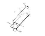
この記録紙押さえ部材7の詳細を図3に示す。本実施形態に示す記録紙押さえ部材7は、記録紙Pの幅方向端部をその上方から覆う押さえ板71と、該押さえ板71をプラテン6の表面に取り付けるための取り付け板72とによって構成されている。
【0024】
押さえ板71は、PETシート等の弾性を有する合成樹脂シートによって、記録紙Pの搬送方向に沿う長さがプラテン6における記録紙Pの搬送方向に沿う長さとほぼ同等の平板によって形成されており、その記録紙Pの導入側先端部711は、記録紙Pをその下面側に円滑に導入し得るようにするため、所定の傾斜がつけられている。
【0025】
取り付け板72は、ステンレス薄板等の金属薄板によって、上記押さえ板71の取り付け面となる平板部721を挟んで、一端に、プラテン6の吸引口61に挿入して係合する係合部722と、他端に、プラテン6における記録紙Pの搬送方向の縁部に圧接して係止するための係止部723とが一体に折り曲げ形成されている。
【0026】
上記係合部722は、図4に示すように、取り付け板72の一端側の両側部が同一方向(押さえ板71とは反対側)に折り曲げられており、その先端に記録紙Pの搬送方向に沿って突出する係合爪722a、722aが一体に形成されている。この係合爪722a、722aを記録紙Pの幅方向端部の位置に応じて、プラテン6における記録紙Pの幅方向端部よりも外側に位置する吸引口61、例えば記録紙Pの幅方向端部外側の近傍に位置する吸引口61に挿入することで、記録紙押さえ部材7を吸引口61に対して係合するようになっている。図示例では2つの係合爪722a、722aを突設した係合部722としているが、係合部722はプラテン6の吸引口61に挿入して係合するものであれば特に問わず、その具体的構造はプラテン6の吸引口61の間隔及び形状等によって適宜変更される。
【0027】
一方、上記係止部723は、取り付け板72の他端側がプラテン6側に向けて折り曲げられると共に、更にその端部が上記係合部722とは反対側に向けて折り曲げられて略Z型に形成されており、その最端部側をユーザーが摘んで操作するための摘み部723aとしている。
【0028】
そして、上記押さえ板71が上記取り付け板72の平板部721に対して両面テープや接着剤等の適宜の接着手段によって貼着されることで、記録紙押さえ部材7が構成される。押さえ板71における取り付け板72との貼着部位を図3において破線で示す。本実施形態では、押さえ板71の導入側先端部711が取り付け板72の係合部722側に配置されるように貼着されている。
【0029】
かかる記録紙押さえ部材7は、プラテン6の表面に適正に取り付けられた状態で、その上方をキャリッジ4が通過しても接触しない程度の厚みで構成される。また、図2及び図3に示されるように、押さえ板71は、取り付け板72の平板部721の先端側から大きく延出している。更に、平板部721の幅は、押さえ板71の幅よりも幅狭に形成されており、これにより押さえ板71は取り付け板72の平板部721から側方にはみ出して押さえ部712を形成している。この押さえ部712のはみ出し方向は、図1に示す一対の記録紙押さえ部材7、7においてそれぞれ反対となっており、この押さえ部712がそれぞれ記録紙Pの幅方向端部を覆うことで、押さえ板71の下面とプラテン6の表面との間に記録紙Pを通過させるようになっている。
【0030】
次に、かかる記録紙押さえ部材7のプラテン6への取り付け方法について図5を用いて説明する。
【0031】
まず、記録紙押さえ部材7の係合部722に形成された各係合爪722a、722aを、プラテン61における記録紙Pの幅方向端部の外側近傍に位置する吸引口61、61に潜り込ませて挿入する(図5(a))。ここでの挿入動作は、押さえ板71の導入側先端部711が取り付け板72の係合部722側に位置しているため、記録紙Pの搬送方向下流側から上流側に向けて、プラテン6の表面に対して斜めに挿入することによって行われる。このとき押さえ板71の先端側がプラテン6の表面に当接するが、自身の弾性によって容易に変形し、挿入動作を円滑に行うことができる。
【0032】
次いで、記録紙押さえ部材7の他端側をプラテン6の表面に向けて押圧する(図5(b))。このとき係止部723は、プラテン6における記録紙Pの搬送方向下流側の縁部62に当接するが、平板部721と一体に折り曲げ形成されていることによって弾性的に変形し、更に押圧されることで弾性反力によって縁部62に圧接して係止される(図5(c))。これにより記録紙押さえ部材7は、プラテン6の表面に弾性的に取り付けられて固定される。記録紙押さえ部材7をプラテン6から取り外す際は、摘み部723aを摘んで上記と逆の操作を行えばよい。
【0033】
そして、記録紙Pの種類が変更された場合には、その幅方向位置に応じて記録紙押さえ部材7のプラテン6表面に対する取り付け位置を変更する。このとき、予め定められている規格幅の記録紙Pの幅方向端部の位置に対応して、プラテン6表面又は係合部722を係合させるための吸引口61に記録紙押さえ部材7の取り付け位置を示す目印を設けてもよい。
【0034】
かかる記録紙押さえ部材7は、押さえ板71と取り付け板72とからなる極めて簡易な構造で済み、低コストで構成することが可能である。また、係合部722と係止部723とによって、プラテン6の吸引口61及び縁部62を利用してその表面に取り付けられるため、係合部722を係合させるための吸引口61の位置を任意に選択することで、プラテン6表面の幅方向の任意の位置に対して容易に着脱可能である。従って、現行のプラテン形状を何ら変更する必要なくそのまま利用できる上に、プリンタにおいて使用される記録紙Pの多種の幅に伴う記録紙Pの幅方向端部の位置変更にも容易に対応することができる。
【0035】
また、記録紙押さえ部材7の取り付けはプラテン6の表面側から行われ、記録紙Pの幅方向からは行われないため、従来のように記録紙Pをその幅方向から押し付けることによって記録紙Pを損傷してしまうような問題は発生しない。更に、吸引口61からの吸引動作によって記録紙押さえ部材7もプラテン6の表面に吸引されるので、記録紙Pの幅方向端部の浮き上がりを押さえる効果をより助長させることができる。
【0036】
ところで、かかる記録紙押さえ部材7は、以上のようにユーザーによってプラテン6に取り付けられるため、取り付け時にその係止部723の押圧操作が不十分となる場合が想定される。このため、本実施形態に示すインクジェットプリンタのように、記録紙Pの幅方向に亘ってキャリッジ4が往復移動するものにおいては、キャリッジ4に、その往復移動時に記録紙押さえ部材7を自動的に押圧してプラテン6に確実に係止させるための強制係止手段を設けることが好ましい。
【0037】
本実施形態における強制係止手段は、図6に示すように、キャリッジ4の記録紙Pに対向する面41に設けられた凸部8によって構成されている。この凸部8は、キャリッジ4の記録紙Pに対向する面41において、プラテン6に取り付けられた記録紙押さえ部材7の係止部723側の平板部721上方を通過する位置に設けられており、キャリッジ4の移動方向に沿って若干傾斜状に形成されている。そして、その記録紙P側への最大突出高さは、記録紙押さえ部材7が図5(c)のように適正にプラテン6に係止されている状態で、その係止部723側の平板部721上面に接する程度とされている。
【0038】
従って、記録紙押さえ部材7の係止部723の押圧が不十分なために、図7(a)に示すように記録紙押さえ部材7がプラテン6の表面から浮き上がった状態であっても、キャリッジ4が記録紙押さえ部材7の上方を通過する際に、上記凸部8が係止部723側の平板部721上面を傾斜面に沿ってプラテン6側に向けて押圧して圧接するため、図7(b)に示すように記録紙押さえ部材7の取り付け状態を自動的に適正状態とすることができる。
【0039】
なお、この強制係止手段としての凸部8は、図6ではキャリッジ4の移動方向一方端部側にのみ設けられているが、キャリッジ4の移動方向両端部にそれぞれ設けられていると、キャリッジ4が左右いずれの方向に移動する際にも記録紙押さえ部材7を押圧可能となるので、プリント動作中に不意に記録紙押さえ部材7がプラテン6から外れて浮き上がるようなことがあっても、確実に記録ヘッド5との衝突を避けることができると共に、常に記録ヘッド5が記録紙P上に差し掛かる前に自動的に復帰させることができるために好ましい。
【0040】
また、図6及び図7に示す強制係止手段は、キャリッジ4の移動方向に沿って延びる複数列の突条によって形成した凸部8により構成しているが、強制係止手段はキャリッジ4の移動によって記録紙押さえ部材7を押圧し、プラテン6に係止させることが可能であれば任意であり、図示しないが、例えばキャリッジ4の記録紙Pに対向する面41からドーム状に突出する1又は複数の半球状の凸部によって構成したり、キャリッジ4の移動方向に沿って回転可能な1又は複数の車輪の一部を記録紙Pに対向する面41から突出させて凸部を構成するようにしてもよい。
【0041】
図8は、記録紙押さえ部材7の係止部723の別の構造を示している。この係止部723は、取り付け板72の他端側を折り曲げて形成する代わりに、該他端の下面側に突出する圧入体723bを設けて構成している。この圧入体723bは、合成樹脂、合成ゴム等の適度な弾性を有する部材によって、先端側に向かうに従って漸次小径となる略円錐状に形成されており、プラテン6の縁部62に押圧されると、図9に示すように、その大径側が徐々に縁部62に食い込んでいくことによって、記録紙押さえ部材7の他端側を上記縁部62に対して楔の要領で圧入状に取り付けるようになっている。
【0042】
この場合、プラテン6の上記縁部62には、図10に示すように、幅方向に亘って連続する三角歯62a等を設けることによって凹凸状とし、上記圧入体723bの圧入が凹部内において行われるようにすると、圧入体723bとプラテン6の縁部62との係止状態をより強固にすることができるために好ましい。
【0043】
この図8〜10に示す記録紙押さえ部材7では、取り付け板72自体は必ずしも弾性を有していなくてもよいため、取り付け板72の材質選択の自由度が高い。
【0044】
図11は、記録紙押さえ部材7の係止部723の更に別の構造を示している。この係止部723は、取り付け部72の他端側が押さえ板71とは反対側に向けて略L型に折り曲げられ、その折り曲げ部723cに、プラテン6の縁部62に対してその側面側、すなわち記録紙Pの搬送方向に沿う方向から締め付けることにより記録紙押さえ部材7をプラテン6に取り付けるための取り付け螺子723dが設けられている。
【0045】
これによって、この記録紙押さえ部材7は、図12に示すように、プラテン6を上記折り曲げ部723cと吸引口61に挿入して係合する係合部722との間で挟着するようにして固定される。この記録紙押さえ部材7によれば、以上説明したような取り付け板72による弾力や圧入体723bの圧入によるプラテン6への固定に比べて、より確実に固定させることができる。
【0046】
【発明の効果】
本発明によれば、簡単な部品構成で、記録紙を損傷することなく、容易に取り付けが可能で、且つ多種幅の記録紙にも簡単に対応可能な記録紙押さえ構造を提供することができる。
【図面の簡単な説明】
【図1】本発明に係る記録紙押さえ構造を適用したインクジェットプリンタの一例を示す要部平面図
【図2】記録紙押さえ構造の要部を示す斜視図
【図3】記録紙押さえの部材の一例を示す分解斜視図
【図4】係合部の構造を示す部分斜視図
【図5】(a)〜(c)は記録紙押さえ部材の取り付け方法を示す説明図
【図6】キャリッジにおける強制係止手段の構成を示すキャリッジの記録紙に対向する面から見た斜視図
【図7】(a)(b)は強制係止手段の作用を示す説明図
【図8】係止部の別の構造を有する記録紙押さえ部材を示す斜視図
【図9】図8に示す記録紙押さえ部材の取り付け状態を示す説明図
【図10】図8に示す記録紙押さえ部材の係止部の取り付け状態を示す部分平面図
【図11】係止部の更に別の構造を有する記録紙押さえ部材を示す斜視図
【図12】図11に示す記録紙押さえ部材の取り付け状態を示す説明図
【符号の説明】
1:搬送ローラ
2:紙押さえローラ
3:キャリッジガイド
4:キャリッジ
41:記録紙に対向する面
5:記録ヘッド
6:プラテン
61:吸引口
62:縁部
62a:三角歯
7:記録紙押さえ部材
71:押さえ板
711:導入側先端部
712:押さえ部
72:取り付け板
721:平板部
722:係合部
722a:係合爪
723:係止部
723a:摘み部
723b:圧入体
723c:折り曲げ部
723d:取り付け螺子
8:凸部[0001]
BACKGROUND OF THE INVENTION
The present invention relates to a recording paper pressing structure for an ink jet printer that prevents the recording head and the recording paper from contacting each other by preventing the end of the recording paper in the width direction from rising.
[0002]
[Prior art]
Conventionally, in an ink jet printer, a recording paper pressing structure that prevents contact between the recording head and the widthwise end of the recording paper is provided by a rubber roller arranged upstream of the recording unit that discharges ink from the recording head toward the recording paper. A method of pressing a recording sheet is known. Also known is a structure in which a large number of suction ports are formed in a platen disposed on the back side of the recording paper in the recording unit, and the recording paper during recording is brought into close contact with the platen by a suction operation using a fan motor as a power source. ing.
[0003]
Possible causes of contact between the recording head and the widthwise end of the recording paper are that the recording paper is left in wet air and the widthwise end of the recording paper is warped or rolled into a cylindrical shape. In the case of this recording paper, it may be rounded due to deformation of the recording paper when pulled out from the roll, but for this reason, the rubber roller above the recording unit is separated from the recording unit by pressing with the rubber roller, so the rubber roller As soon as the pressure of the recording paper is released, the recording paper floats up again due to the flexibility of the recording paper itself, so that the effect of preventing the lifting is uncertain.
[0004]
Also, in the structure where the recording paper is brought into close contact with the platen by the suction operation, the suction force of the platen is not enough to make the recording paper that is lifted up close, and the recording paper may remain lifted from the platen. Uncertain.
[0005]
Therefore, as a means for reliably preventing the lifting of the widthwise end portion of the recording paper that is easily touched particularly when the carriage is moved, a recording paper pressing member made of an elastic thin plate such as a PET sheet or a spring steel plate is used. There has been proposed a recording paper pressing structure that suppresses lifting of the end portion in the width direction.
[0006]
Patent Document 1 discloses a configuration in which the recording paper pressing member is provided upstream of the recording unit in the recording paper conveyance direction. However, when this method is adopted, the recording paper that has passed through the recording paper pressing member is lifted back at the end in the width direction due to the flexibility of the paper, and has little effect on suppressing the lifting of this portion. .
[0007]
Patent Document 2 discloses a configuration in which a recording sheet pressing member is provided at an end of the recording section in the width direction of the recording sheet. In the case of using recording paper of various widths in such a configuration, it is necessary to move the position of the recording paper pressing member in accordance with the position change of the width direction end portion of the recording paper. There is no disclosure regarding the configuration relating to the position change.
[0008]
Furthermore, in Patent Document 3, the position can be changed by fixing the recording paper pressing member to the platen so as to be slidable in the width direction of the recording paper, using a groove provided in parallel with the recording paper width direction as a guide. There has also been proposed a recording paper pressing structure that can prevent the end of the recording paper in the width direction from being lifted. However, in this structure, since various components are used to slide the recording paper pressing member along the guide groove, and a separate structure for fixing the recording paper pressing member to the platen is required, the product cost is reduced. In addition to the increase, the user also needs troublesome work to fix the recording paper pressing member to the platen. Moreover, when the recording paper pressing member is slid and fixed to the platen with the recording paper set in the recording portion, the recording paper pressing member can slide to a position narrower than the recording paper width. There is a problem that the pressing member pushes up the recording paper from the platen to damage the recording paper, or the recording paper floats from the platen.
[0009]
[Patent Document 1]
Japanese Utility Model Publication No. 7-40144 [Patent Document 2]
Japanese Patent Laid-Open No. 2002-249260 [Patent Document 3]
Japanese Patent Laid-Open No. 11-208046
[Problems to be solved by the invention]
Accordingly, the present invention provides a recording paper pressing structure for an ink jet printer that can be easily attached without damaging the recording paper with a simple component structure and can easily cope with recording paper of various widths. This is the issue.
[0011]
[Means for Solving the Problems]
The above problems are solved by the following inventions.
[0012]
According to a first aspect of the present invention, there is provided a recording paper pressing structure for an ink jet printer that suppresses lifting of a width direction end portion of a recording paper conveyed between the recording head and the platen, and a large number of holes formed on the surface of the platen. A recording paper pressing structure for an ink jet printer, wherein a recording paper pressing member is detachably attached to an arbitrary suction port among the suction ports.
[0013]
According to a second aspect of the present invention, the recording paper pressing member includes an engaging portion that is inserted into and engaged with the suction port of the platen at one end, and an engagement portion that presses and engages the edge of the platen at the other end. The recording paper pressing structure for an ink jet printer according to claim 1, further comprising a stop portion.
[0014]
According to a third aspect of the present invention, the recording paper pressing member is configured such that the platen is sandwiched between an engaging portion which is inserted into the suction port of the platen and engaged at one end and the engaging portion at the other end. The recording paper pressing structure for an ink jet printer according to claim 1, further comprising a mounting screw to be mounted.
[0015]
According to a fourth aspect of the present invention, the recording head is mounted on a carriage provided so as to be capable of reciprocating in the width direction of the recording paper, and the recording paper pressing member lifted from the platen is mounted on the carriage. 3. A recording paper pressing structure for an ink jet printer according to claim 2, further comprising forcible locking means for pressing toward the platen when the carriage moves.
[0016]
According to a fifth aspect of the present invention, there is provided the recording paper pressing structure for an ink jet printer according to the fourth aspect, wherein the forcible locking means is constituted by a convex portion protruding from a surface of the carriage facing the recording paper. It is.
[0017]
DETAILED DESCRIPTION OF THE INVENTION
Hereinafter, embodiments of the present invention will be described with reference to the drawings.
[0018]
FIG. 1 is a main part plan view showing an example of an ink jet printer to which a recording paper pressing structure according to the present invention is applied, and FIG. 2 is a perspective view showing the main part of the recording paper pressing structure.
[0019]
As shown in FIG. 1, the recording paper P includes a transport roller 1 disposed on the back side thereof and a plurality of paper pressers disposed on a surface (recording surface) opposite to the transport roller 1 with the recording paper P interposed therebetween. It is sandwiched between the rollers 2 and is transported along the direction A indicated by the arrow in the figure by rotating the transport roller 1 by a drive motor (not shown).
[0020]
A recording unit that records an image on the recording surface of the recording paper P is formed on the downstream side of the conveying roller 1 and the paper pressing roller 2. A carriage guide 3 is installed over the recording section in the width direction of the recording paper P, and a carriage 4 is attached to the carriage guide 3 so as to be reciprocally movable in the left-right direction in the figure by driving means (not shown). The carriage 4 is mounted with a
[0021]
On the opposite side across the carriage 4 and the recording paper P, the
[0022]
At both ends in the width direction of the recording paper P passing over the
[0023]
Details of the recording
[0024]
The holding
[0025]
The
[0026]
As shown in FIG. 4, the engaging
[0027]
On the other hand, the locking
[0028]
The recording
[0029]
The recording
[0030]
Next, a method for attaching the recording
[0031]
First, the engaging
[0032]
Next, the other end side of the recording
[0033]
When the type of the recording paper P is changed, the attachment position of the recording
[0034]
The recording
[0035]
Further, since the recording
[0036]
By the way, since the recording
[0037]
As shown in FIG. 6, the forcible locking means in the present embodiment is constituted by a
[0038]
Therefore, even when the recording
[0039]
In FIG. 6, the
[0040]
6 and 7 is configured by the
[0041]
FIG. 8 shows another structure of the locking
[0042]
In this case, as shown in FIG. 10, the
[0043]
In the recording
[0044]
FIG. 11 shows still another structure of the locking
[0045]
Thus, as shown in FIG. 12, the recording
[0046]
【The invention's effect】
According to the present invention, it is possible to provide a recording sheet pressing structure that can be easily attached without damaging the recording sheet with a simple component configuration and that can easily cope with recording sheets of various widths. .
[Brief description of the drawings]
FIG. 1 is a main part plan view showing an example of an ink jet printer to which a recording paper pressing structure according to the present invention is applied. FIG. 2 is a perspective view showing a main part of the recording paper pressing structure. FIG. 4 is a partial perspective view showing the structure of the engaging portion. FIGS. 5A to 5C are explanatory views showing a method of attaching the recording paper pressing member. FIG. FIG. 7A and FIG. 7B are explanatory views showing the operation of the forced locking means. FIG. FIG. 9 is a perspective view showing a recording paper pressing member having the structure shown in FIG. 9. FIG. 10 is an explanatory diagram showing a mounting state of the recording paper pressing member shown in FIG. FIG. 11 is a partial plan view showing a recording paper having yet another structure of a locking portion; Explanatory view showing a mounting state of the recording sheet presser member shown in perspective view FIG. 12] FIG 11 even showing components [Description of symbols]
1: Conveying roller 2: Paper pressing roller 3: Carriage guide 4: Carriage 41: Surface facing the recording paper 5: Recording head 6: Platen 61: Suction port 62:
Claims (5)
Priority Applications (1)
| Application Number | Priority Date | Filing Date | Title |
|---|---|---|---|
| JP2003024822A JP3972829B2 (en) | 2003-01-31 | 2003-01-31 | Inkjet printer recording paper presser structure |
Applications Claiming Priority (1)
| Application Number | Priority Date | Filing Date | Title |
|---|---|---|---|
| JP2003024822A JP3972829B2 (en) | 2003-01-31 | 2003-01-31 | Inkjet printer recording paper presser structure |
Publications (2)
| Publication Number | Publication Date |
|---|---|
| JP2004230839A JP2004230839A (en) | 2004-08-19 |
| JP3972829B2 true JP3972829B2 (en) | 2007-09-05 |
Family
ID=32953261
Family Applications (1)
| Application Number | Title | Priority Date | Filing Date |
|---|---|---|---|
| JP2003024822A Expired - Fee Related JP3972829B2 (en) | 2003-01-31 | 2003-01-31 | Inkjet printer recording paper presser structure |
Country Status (1)
| Country | Link |
|---|---|
| JP (1) | JP3972829B2 (en) |
Families Citing this family (19)
| Publication number | Priority date | Publication date | Assignee | Title |
|---|---|---|---|---|
| JP4886567B2 (en) * | 2007-03-27 | 2012-02-29 | キヤノン株式会社 | Inkjet recording device |
| JP4934488B2 (en) * | 2007-04-27 | 2012-05-16 | キヤノン株式会社 | Recording device |
| JP5311019B2 (en) * | 2008-12-24 | 2013-10-09 | セイコーエプソン株式会社 | Recording device |
| JP5409328B2 (en) * | 2009-04-09 | 2014-02-05 | 株式会社セイコーアイ・インフォテック | Recording method |
| JP5409327B2 (en) * | 2009-04-09 | 2014-02-05 | 株式会社セイコーアイ・インフォテック | Recording method |
| JP5440027B2 (en) * | 2009-08-27 | 2014-03-12 | セイコーエプソン株式会社 | Conveying apparatus and recording apparatus |
| JP5342381B2 (en) * | 2009-09-04 | 2013-11-13 | 大日本スクリーン製造株式会社 | Recording medium holding member and ink jet printer |
| JP5552935B2 (en) * | 2010-07-21 | 2014-07-16 | セイコーエプソン株式会社 | Method for confirming mounting position of holding member and recording apparatus |
| US9028160B2 (en) | 2011-11-29 | 2015-05-12 | Hewlett-Packard Development Company, L.P. | Print substrate edge guide |
| JP6428111B2 (en) | 2014-09-30 | 2018-11-28 | セイコーエプソン株式会社 | Medium pressing member and recording apparatus |
| JP6413565B2 (en) | 2014-09-30 | 2018-10-31 | セイコーエプソン株式会社 | Printing device |
| JP6402995B2 (en) * | 2014-10-15 | 2018-10-10 | セイコーエプソン株式会社 | Medium pressing member and recording apparatus |
| US10744801B2 (en) | 2016-03-18 | 2020-08-18 | Hewlett-Packard Development Company, L.P. | Holder device for a printer |
| JP6701899B2 (en) | 2016-04-05 | 2020-05-27 | セイコーエプソン株式会社 | Liquid ejecting apparatus and medium pressing method |
| EP3305533B1 (en) * | 2016-10-04 | 2021-02-17 | Canon Production Printing Holding B.V. | Method for processing a web in an apparatus |
| JP2018103366A (en) * | 2016-12-22 | 2018-07-05 | セイコーエプソン株式会社 | Printer |
| JP6931182B2 (en) | 2017-04-07 | 2021-09-01 | セイコーエプソン株式会社 | Liquid discharge device |
| JP6973033B2 (en) | 2017-12-22 | 2021-11-24 | セイコーエプソン株式会社 | Printing equipment |
| JP7113043B2 (en) * | 2020-04-23 | 2022-08-04 | ローランドディー.ジー.株式会社 | inkjet printer |
-
2003
- 2003-01-31 JP JP2003024822A patent/JP3972829B2/en not_active Expired - Fee Related
Also Published As
| Publication number | Publication date |
|---|---|
| JP2004230839A (en) | 2004-08-19 |
Similar Documents
| Publication | Publication Date | Title |
|---|---|---|
| JP3972829B2 (en) | Inkjet printer recording paper presser structure | |
| JP4070861B2 (en) | Inkjet printer | |
| JP3768929B2 (en) | Recording device | |
| JPH10167507A (en) | Recording device | |
| US6382857B1 (en) | Bearing mechanism and conveying apparatus and recording apparatus | |
| JP3846174B2 (en) | Paper feeding mechanism and image recording apparatus using the paper feeding mechanism | |
| JP6198639B2 (en) | Printing apparatus and sheet support apparatus | |
| US7204483B2 (en) | Sheet media input tray | |
| JP3359205B2 (en) | Recording device | |
| JP2755960B2 (en) | Liquid jet recording device | |
| JP6622376B1 (en) | Clamp member and media cutting device | |
| JP3965576B2 (en) | Image forming apparatus | |
| JP3807486B2 (en) | Feed / discharge tray, recording device | |
| JP2524133B2 (en) | Ink jet recording device | |
| JP2001302012A (en) | Recorder | |
| JP2003118902A5 (en) | ||
| JP3775473B2 (en) | Inkjet recording device | |
| JP3624924B2 (en) | Inkjet printer delivery device | |
| JP3533120B2 (en) | Printer dust removal card holder | |
| JP2002096514A (en) | Tray for carrying recording media, and recorder | |
| JP3768928B2 (en) | Recording device | |
| JPH0577997A (en) | Printing device | |
| JP2005104112A (en) | Recording device | |
| JPH0740144U (en) | Paper press structure for inkjet printers | |
| JP4635608B2 (en) | Liquid ejecting apparatus and recording apparatus |
Legal Events
| Date | Code | Title | Description |
|---|---|---|---|
| A621 | Written request for application examination |
Free format text: JAPANESE INTERMEDIATE CODE: A621 Effective date: 20060125 |
|
| A977 | Report on retrieval |
Free format text: JAPANESE INTERMEDIATE CODE: A971007 Effective date: 20070514 |
|
| TRDD | Decision of grant or rejection written | ||
| A01 | Written decision to grant a patent or to grant a registration (utility model) |
Free format text: JAPANESE INTERMEDIATE CODE: A01 Effective date: 20070522 |
|
| A61 | First payment of annual fees (during grant procedure) |
Free format text: JAPANESE INTERMEDIATE CODE: A61 Effective date: 20070604 |
|
| R150 | Certificate of patent (=grant) or registration of utility model |
Free format text: JAPANESE INTERMEDIATE CODE: R150 |
|
| FPAY | Renewal fee payment (prs date is renewal date of database) |
Free format text: PAYMENT UNTIL: 20100622 Year of fee payment: 3 |
|
| FPAY | Renewal fee payment (prs date is renewal date of database) |
Free format text: PAYMENT UNTIL: 20100622 Year of fee payment: 3 |
|
| FPAY | Renewal fee payment (prs date is renewal date of database) |
Free format text: PAYMENT UNTIL: 20110622 Year of fee payment: 4 |
|
| FPAY | Renewal fee payment (prs date is renewal date of database) |
Free format text: PAYMENT UNTIL: 20110622 Year of fee payment: 4 |
|
| FPAY | Renewal fee payment (prs date is renewal date of database) |
Free format text: PAYMENT UNTIL: 20120622 Year of fee payment: 5 |
|
| FPAY | Renewal fee payment (prs date is renewal date of database) |
Free format text: PAYMENT UNTIL: 20130622 Year of fee payment: 6 |
|
| S531 | Written request for registration of change of domicile |
Free format text: JAPANESE INTERMEDIATE CODE: R313531 |
|
| S533 | Written request for registration of change of name |
Free format text: JAPANESE INTERMEDIATE CODE: R313533 |
|
| R350 | Written notification of registration of transfer |
Free format text: JAPANESE INTERMEDIATE CODE: R350 |
|
| LAPS | Cancellation because of no payment of annual fees |