JP3970052B2 - Image processing device - Google Patents
Image processing device Download PDFInfo
- Publication number
- JP3970052B2 JP3970052B2 JP2002051355A JP2002051355A JP3970052B2 JP 3970052 B2 JP3970052 B2 JP 3970052B2 JP 2002051355 A JP2002051355 A JP 2002051355A JP 2002051355 A JP2002051355 A JP 2002051355A JP 3970052 B2 JP3970052 B2 JP 3970052B2
- Authority
- JP
- Japan
- Prior art keywords
- color
- image processing
- image
- color recognition
- processing apparatus
- Prior art date
- Legal status (The legal status is an assumption and is not a legal conclusion. Google has not performed a legal analysis and makes no representation as to the accuracy of the status listed.)
- Expired - Fee Related
Links
- 239000003550 marker Substances 0.000 claims description 26
- 238000000034 method Methods 0.000 claims description 12
- 238000004458 analytical method Methods 0.000 claims description 7
- 238000004364 calculation method Methods 0.000 claims description 2
- 238000010586 diagram Methods 0.000 description 11
- 230000006870 function Effects 0.000 description 10
- 230000005855 radiation Effects 0.000 description 9
- 239000003086 colorant Substances 0.000 description 6
- 238000002372 labelling Methods 0.000 description 6
- 238000003491 array Methods 0.000 description 1
- 238000001514 detection method Methods 0.000 description 1
- 230000000694 effects Effects 0.000 description 1
- 239000000284 extract Substances 0.000 description 1
- 238000005286 illumination Methods 0.000 description 1
- 238000003384 imaging method Methods 0.000 description 1
- 230000003287 optical effect Effects 0.000 description 1
Images


Classifications
-
- G—PHYSICS
- G06—COMPUTING; CALCULATING OR COUNTING
- G06V—IMAGE OR VIDEO RECOGNITION OR UNDERSTANDING
- G06V10/00—Arrangements for image or video recognition or understanding
- G06V10/40—Extraction of image or video features
Landscapes
- Engineering & Computer Science (AREA)
- Physics & Mathematics (AREA)
- General Physics & Mathematics (AREA)
- Multimedia (AREA)
- Theoretical Computer Science (AREA)
- Image Analysis (AREA)
- Image Processing (AREA)
Description
【0001】
【発明の属する技術分野】
画像から特定色を認識するための色認識パラメータを設定するものに関する。
【0002】
【従来の技術】
画像からのカラーマーカー認識などのためには、画像から特定の色を認識する必要がある。計算機による色認識は、画面上の各画素の色を示す値があらかじめ定められた範囲にあるかで特定の色どうかを判定することで行う。
【0003】
例えば、赤い色を検出する場合には、画素を構成するピクセルの色差信号Cb,Crの範囲を
−1<Cb<+3かつ+25<Cr<+127
と指定していた。この場合、赤という色を指定するのに、(−1,+3,+25,+127)という数値の組を使用していた。
【0004】
通常この特定色を指定するための範囲は、照明条件などが変わると条件に合わせて調整しなおす必要がある。例えば蛍光灯下で使用していた色認識パラメータは、白熱灯下では調整しなおす必要がある。
【0005】
従来この色認識パラメータの調整は、オペレータが認識率を観察しながら、数値をマニュアル調整することにより行われていた。
【0006】
【発明が解決しようとする課題】
だがこのような色認識パラメータの調整は、オペレータの熟練が必要であり、また各色ごとに作業を繰り返す必要があり効率が悪かった。
【0007】
また、このような数値の組による色指定方法は直感的でなく、認識する色を指定しずらかった。
【0008】
本発明は、この点に鑑みてなされたものであり、色見本の撮影画像を解析することにより色認識パラメータが設定できるようにし、ユーザの色認識パラメータの設定にかかる労力を軽減することを目的とする。
【0009】
また、色認識パラメータをグラフィカルな表示に基づき調整できるようにすることにより、調整を直感的に簡単に行えるようにすることを他の目的とする。
【0010】
【課題を解決するための手段】
上記目的を達成するために本発明は以下の構成を有する。
【0011】
本発明の画像処理装置は、画像から特定色を認識するための色認識パラメータを設定する画像処理装置であって、予め決められたパターンでマーカーの色が配置された色見本を撮影する撮影手段と、前記撮影手段により撮影された画像からマーカー領域を検出し、検出したマーカー領域の画素の色情報を2次元平面にプロットした色分布グラフ上の前記プロットされた点を含む最小の多角形を求め、求めた多角形から前記マーカーを検出するための色認識パラメータを求める解析手段と、前記解析手段により求めた色解析パラメータを記憶する記憶手段とを備える。
【0014】
【発明の実施の形態】
(実施形態1)
本実施形態は、画像中の特定色のマーカーを見つける画像処理装置のために、特定色のマーカーを検出するための色パラメータを設定する色パラメータ設定装置に関する。
【0015】
図1は本実施形態のシステムの全体図である。本実施形態は計算機のソフトウェアとして実装されている。本実施形態のシステムは計算機100、色見本パネル200、ビデオカメラ300からなる。
【0016】
色見本パネル200をビデオカメラ300で撮影し、その映像を計算機100に取り込む。計算機100は取り込んだ映像から色見本パネル200の色情報を抽出し、色見本パネルに含まれるマーカーを認識するための色パラメータを求める。
【0017】
色パラメータは、図2のようにCb,Cr平面における領域を示すパラメータである。Cb,Cr平面は、輝度・色差信号の色みを示す色差信号によって定義される色平面である。領域はCb,Cr平面で原点から放射線状に広がる長方形の領域である。色パラメータは、図3に示されるように、長方形の中心点、長方形の円周方向の大きさ、長方形の放射線方向の大きさの各々を示すパラメータが含まれる。色認識プログラムはこの色パラメータを用い、画素の色のCb,Cr値が、色パラメータで示される長方形領域に入っているかどうかで色認識を行う。
【0018】
色見本パネル200を図4に示す。本実施形態では、マーカーとして6色を用意し、色見本パネル内に2行3列に配置した。色見本パネル200にはガイドマーカー210が各マーカーの4隅に配置されるように格子状に配置されている。計算機100はこのガイドマーカー210を認識して、取り込んだ画像中での色見本パネル200の位置を認識する。
【0019】
本実施形態の動作画面を図5に示す。動作画面は、メインウィンドウ500とカラーチャートウィンドウ600からなる。
【0020】
メインウィンドウ500はメニューバーを持ち、本実施形態全体の制御を行うことができる。メインウィンドウ500の下半分には実写画像、上半分には画像認識映像が表示される。
【0021】
画像認識映像は、実写画像を2値化し得られた白黒画像に、2値画像の解析結果を合わせて表示した。2値化は、画面全体の明るさの平均値を求め、平均値を閾値として用いる。2値画像を解析することによりマーカー領域510を認識した時は、2値画像に赤で認識したマーカー領域の位置を表示する。なお、本実施形態では6つのマーカーを用いているので、6つのマーカー領域が検出されている。
【0022】
カラーチャートウィンドウ600は、横軸をCb、縦軸をCrにとったグラフである。色見本パネルを認識した結果得た色見本のCb,Cr値に点をプロットするために使用する。
【0023】
本実施形態のプログラムは、キャプチャした画像の認識結果から画面上の色見本パネルの位置を特定し、色見本のCb,Cr値を得る。そして、取得した色見本のCb,Cr値をカラーチャートウィンドウ上にプロットする。
【0024】
プロットされる点の色は、色見本ごとに変えてある。このウィンドウに表示されたカラーチャートをもとに、色認識パラメータを作成する。
【0025】
プログラムは常にビデオカメラ300から画像をキャプチャしており、色見本パネルを認識するとその結果をカラーチャートウィンドウ200にプロットする。色見本パネル200の角度を変えるなどすると、多くの場合図6のような形にカラーチャートがプロットされる。
【0026】
色認識パラメータの作成は、メインウィンドウ500のメニューバーから「calibrate」を選ぶことで行う。
【0027】
色認識パラメータは、カラーチャートウィンドウ600にプロットされた色領域を元に作成される。色認識パラメータは、カラーチャートの点が作る島のなかで最大のものを内包する最小の長方形である。例として図7を示す。
【0028】
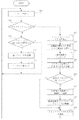
本実施形態のプログラムのメインルーチンのフローチャートを図8に示す。プログラムはイベントドリブンで動作している。ビデオカメラ300から1画面キャプチャが完了するとキャプチャイベントが起きる。またメニューから「calibrate」を選択すると、色パラメータ作成イベントが起きる。メインルーチンは通常、イベント待ちをしており(S10)、発生したイベントに従い(S11、S12)、キャプチャイベント処理(S12〜S19)、色パラメータ作成処理(S21〜S22)を行う。
【0029】
キャプチャイベントが起きると、キャプチャした画面を取り込み、メインウィンドウ500の下半分に取り込んだ画像を表示する(S12)。
【0030】
そして画面全体の明るさの平均値を計算し、画面を構成する各画素に対して、平均値を用いて2値化する(S13)。これは、各画素を示す輝度・色差信号の輝度信号を用いて処理する。
【0031】
2値化画像に対してラベリングを行い、取り込んだ画面中に写った色見本パネル200のガイドマーカー210と思われる点のリストを作る(S14)。ラベリングのアルゴリズムについては、よく知られているのでここでは説明しない。
【0032】
ラベリング結果から格子状に4行3列に並んだ点をガイドマーカーとして検出し、そして画面に写った色見本パネル200を認識する(S15)。ラベリングにより作った点のリストから格子状に並んだ点を探すには、ハフ変換により直線に並んだ点を探し、それらの直線の組み合わせを評価し、その結果から認識する。ハフ変換のアルゴリズムはよく知られているので、ここでは説明しない。
【0033】
色見本パネル200が見つかった場合(S16)には、色見本パネル200の位置からそれぞれの色見本(6色)の場所を計算し、元画面の対応する場所の色情報の平均を計算する(S17)。色見本パネル200が見つからない場合にはS19に進む。
【0034】
また得た色情報は同時に、256×256の配列に格納する。この配列はカラーチャートの各点に対応する。初期状態では配列はすべて0が埋められている。そして得た色情報に従い、要素(Cb+128,Cr+128)に色見本のID、1〜6が代入される。
【0035】
計算した色情報を、カラーチャートウィンドウ600にプロットする(S18)。
【0036】
最後にメインウィンドウ500の上半分に、2値化した画像を白黒画像として表示する(S19)。また、色見本パネルを探す過程で見つけた直線に並んだ点を緑で、色見本パネル200が見つかっている場合には、色見本パネルの位置を赤で表示する。
【0037】
一方、色パラメータ作成イベントが起きると(S20)、カラーチャート200の情報を格納した256×256の配列を元に、色パラメータを計算する(S21)。配列の内容をラベリングし、各色ごとにもっとも面積の大きい島を探す。それらの島の中心点を色パラメータのCb,Crの値とし、それらの島に図3のように外接する長方形の大きさを、それらの色の色パラメータとして記録する。
【0038】
得た色パラメータを、ファイルに書き出す(S22)。より具体的には、カラーIDと長方形の中心、長方形の放射線方向の大きさ、長方形の円周方向の大きさを書き出す。
【0039】
本実施形態によれば、色見本を撮影することにより色認識パラメータを設定することができ、色認識パラメータの設定にかかるユーザの労力を軽減することができる。また、色見本には複数のマーカーが、マーカーを囲むように格子状に配置されたガイドマーカーとともに含まれているので、色見本の撮影画像からマーカー領域を高精度に検出することができる。本実施形態では明るさを示す信号のみを用いて簡単かつ高精度に検出することができる。また、図2に示されるように複数のマーカーが異なる色相を有しているので、色みを示す信号を用いて高精度に認識することができ、また、色認識パラメータも簡単にすることができる。
【0040】
(実施形態2)
本実施形態は画像中の特定の色のマーカーを見つける画像処理装置である。
【0041】
図9は本実施形態の全体図である。本実施形態は計算機のソフトウェアとして実装されている。本実施形態は計算機100、ビデオカメラ200、カラーマーカー300〜306からなる。
【0042】
ビデオカメラ200でカラーマーカー300〜305を撮影し、その映像を計算機100に取り込む。計算機100は取り込んだ映像から、カラーマーカー300〜305を検出し、その領域の重心を計算する。計算結果はネットワークを通じて出力する。本実施形態の動作の模式図を図10に示す。
【0043】
本実施形態の実行画面を図11に示す。実行画面は、コントロールウィンドウ1000、プレビューウィンドウ1100、カラーチャートウインドウ1200で構成される。
【0044】
カラーチャートウィンドウ1200は、縦軸をCb、横軸をCrとする平面を表す。認識する色の色パラメータは、Cb,Cr平面で原点から放射線状に広がる長方形の色認識領域1201、1202、1203、1204、1205、1206で表される(図12)。色認識プログラムは画素の色をCb,Crの値に変換したとき、これらの色領域1201、1202、1203、1204、1205、1206に入っているかどうかで画素の色を判定する。
【0045】
色認識領域1201、1202、1203、1204、1205、1206は、実施形態1と同様に、長方形の中心点、円周方向の長さ、放射線方向の長さにより特定される。
【0046】
カラーマーカー300、301、302、303、304、305の色に対応する色認識領域1201、1202、1203、1204、1205、1206を指定することにより、カラーマーカーの識別を行う。
【0047】
色認識領域1201、1202、1203、1204、1205、1206は、カラーチャートウィンドウにおいて、マウスでドラッグすることで移動、大きさを変更することができる。色認識領域のどの部分をドラッグするかにより操作は変わる。
【0048】
色認識領域の中心部分でマウスをドラッグした場合には、色認識領域を移動させることができる(図13)。ドラッグが終わり、マウスUPした地点が新しい色認識領域の中心点となる。移動は色認識領域の平行移動ではなく原点を中心とした回転移動であり、移動した色認識領域もまた、原点から放射線状に広がる長方形となる。
【0049】
色認識領域の端をマウスでドラッグした場合には、色認識領域の大きさを変えることができる(図14)。ドラッグが終わり、マウスUPした地点が新しい長方形の端となる。
【0050】
コントロールウィンドウ1000はプレビューウィンドウ1100のプレビュー切り替えスイッチ1001、1002を持つ。プレビュー切り替えスイッチ1001、1002を切り替えると、プレビューウィンドウ1100に表示される内容が、ビデオカメラ200の画像そのもの、色認識した結果にそれぞれ切り替わる。
【0051】
プレビューウィンドウ1100に表示される色認識結果を見ながら、色認識領域1201、1202、1203、1204、1205、1206をグラフィカルに操作することで、カラーマーカー300、301、302、303、304、305の色と、色認識領域1201、1202、1203、1204、1205、1206の認識する色が一致するよう調整することができる。
【0052】
本実施形態のプログラムのメインルーチンのフローチャートを図15に示す。
【0053】
プログラムはイベントドリブンで動作している。ビデオカメラ200から1画面キャプチャが完了するとキャプチャイベントが起きる。またカラーチャートウィンドウ1200内でマウスをドラッグすると、カラーチャートのマウスイベントが起きる。コントロールウィンドウ内のボタンを選択すると、コントロールウィンドウイベントが起きる。
【0054】
メインルーチンは通常、イベント待ちをしており(S100)、発生したイベント(ビデオキャプチャ完了イベントS101、カラーチャートウィンドウイベントS103、コントロールウィンドウイベントS105)に従い、ビデオキャプチャイベント処理(S102)、カラーチャートウィンドウイベント処理(S104)、コントロールウィンドウイベント処理(S106)を行う。
【0055】
図16はカラーチャートイベントが発生したとき処理(S104)の内部のフローチャートである。
【0056】
S200において、マウスダウンイベントが生じたときは、マウス座標の近傍に色認識領域1201、1202、1203、1204、1205、1206の中心点があるかどうかを調べる(S202)。
【0057】
もし近傍に色認識領域の中心があれば、変数「ドラッグモード」に「中心移動中」を代入し、変数「注目している色領域認識」にその色認識領域のIDをする(S203)。
【0058】
もし近傍に色認識領域の中心がなければ、マウス座標の近傍に色認識領域1201、1202、1203、1204、1205、1206の原点に近い方の端があるかどうかを調べる(S204)。
【0059】
もし近傍に色認識領域の原点よりの端があれば、変数「ドラッグモード」に「内部端点移動中」を代入し、変数「注目している色領域認識」にその色認識領域のIDをする(S205)。
【0060】
もし近傍に色認識領域の原点よりの端がなければ、マウス座標の近傍に色認識領域1201、1202、1203、1204、1205、1206の原点からはなれた端があるかどうかを調べる(S206)。
【0061】
もし近傍に色認識領域の原点からはなれた端があれば、変数「ドラッグモード」に「外部端点移動中」を代入し、変数「注目している色領域認識」にその色認識領域のIDをする(S207)。
マウス座標の近傍に色認識領域1201、1202、1203、1204、1205、1206の中心点も端もなければ、変数「ドラッグモード」に「NULL」を代入する(S208)。
【0062】
マウスアップイベントが生じたときは、変数「ドラッグモード」により処理を変える(S220、S222、S224)。
【0063】
変数「ドラッグモード」が「中心移動中」である場合は、変数「注目している色認識領域」で指定される色認識領域の中心座標を、マウス座標で置き換える(S221)。
【0064】
変数「ドラッグモード」が「内部端点移動中」である場合は、変数「注目している色認識領域」で指定される色認識領域の色パラメータのうち、中心座標と放射線方向の大きさを次の方法で更新する。
【0065】
x,yを元の中心座標、radiation_lenを元の放射線方向の大きさ、mouse_x,mouse_yをマウス座標とする。また新しい色パラメータの、新たな中心座標をnew_x,new_yを、新たな放射線方向の大きさをnew_radiation_lenとすると、次の式でそれらを求めて色パラメータを更新する(S223)。
【0066】
angle=atan2(y,x);
x_offset=radiation_len*cos(angle)/2;
y_offset=radiation_len*sin(angle)/2;
opposite_x=x−x_offset;
opposite_y=y−y_offset;
new_x=(mouse_x+opposite_x)/2;
new_y=(mouse_y+opposite_y)/2;
new_radiation_len=sqrt(pow(mouse_x−opposite_x,2)+pow(mouse_y−opposite_y,2));
つまり、マウスアップした位置が新たな色認識領域を示す長方形の(原点に近い方の)端となる。
【0067】
同様に変数「ドラッグモード」が「外部端点移動中」である場合も、変数「注目している色認識領域」で指定される色認識領域の色パラメータのうち、中心座標と放射線方向の大きさを次の方法で更新する。
【0068】
x,yを元の中心座標、radiation_lenを元の放射線方向の大きさ、mouse_x,mouse_yをマウス座標とする。また新しい色パラメータの、新たな中心座標をnew_x,new_yを、新たな放射線方向の大きさを new_radiation_lenとすると、次の式でそれらを求めて色パラメータを更新する(S225)。
【0069】
angle=atan2(y,x);
x_offset=radiation_len*cos(angle)/2;
y_offset=radiation_len*sin(angle)/2;
opposite_x=x+x_offset;
opposite_y=y+y_offset;
new_x=(mouse_x+opposite_x)/2;
new_y=(mouse_y+opposite_y)/2;
new_radiation_len=sqrt(pow(mouse_x−opposite_x,2)+pow(mouse_y−opposite_y,2));
色認識領域の位置が更新されると、それに合わせて色認識テーブルの値を更新し(S226)、ウィンドウを再描画する(S227)
【0070】
色認識テーブルは、32768(15bit)の大きさの配列である。配列は15bitのRGB値に対応し、15bitのRGB値がどの色認識領域に対応するかを格納している。色認識テーブルの作成のPAD図を図17に示す。
【0071】
最初に色認識テーブルを0で初期化する(S300)。そして各色認識領域に関して、S302〜S305の処理を行う(S301)。15bit RGBの全ての値0〜0xfffffに関して(S302)、あるRGB値xをCb、Cr各8bitに変換し(S303)、そのCb、Cr値が色認識領域に含まれているなら、色認識テーブルの添字がxの要素にその色認識領域のIDを代入する(S304)。
【0072】
図18はキャプチャイベントが発生したとき処理(S102)の内部のPAD図である。
【0073】
最初にキャプチャ映像を色認識し、図16のように色認識領域の色に対応して6値化する(S201〜203)。色認識領域ID1の部分(青の部分)を1、色認識領域ID2の部分(赤の部分)を2というように色ごとに数値化した画像データに置き換える。それ以外の部分を0とする。
【0074】
キャプチャした映像を受け取り(S300)、映像の全ての画素についてS202〜203の処理を行う(S201)。画素の値(15bit RGB)を添字として色認識テーブルを参照し、画素の値に対応する色認識領域のIDを得る(S202)。得た色認識領域のIDを色認識結果として、映像と同じ大きさ(640*240)の配列に書き出す(S203)。
【0075】
色認識結果として得た配列を元に、プレビューウィンドウを再描画する(S204)。再描画はビューモードにより、キャプチャした画像そのものか、色認識結果を表示する。
【0076】
色認識結果を表示する場合には、配列の各要素について、0なら黒、1なら赤、2なら青…といったように、対応するプレビューウィンドウの各ピクセルを描画する。
【0077】
この画像データに対してラベリングを行い(S205)、「どの色が、どの座標を中心に、どのくらいの面積で存在するか」を示すブロックデータを作成する。ラベリングのアルゴリズムは一般によく知られているのでここでは説明しない。
【0078】
ラベリングの結果について、一定面積(本実施形態では10ドット以上のものに関して、その「色ID、面積、中心点のx,y座標」を組にして登録されたクライアントにネットワークを通じてパケットを送る(S206)。
【0079】
本実施形態によれば、直感的にかつ簡単に色認識パラメータを調整することができる。
【0080】
(他の実施形態)
実施形態1で求められた色認識パラメータを、実施形態2で説明した方法を用いて微調整できるようにしても構わない。
【0081】
また、上記実施形態では輝度・色差信号を用いたが、L*a*b*などの明るさを示す信号と色みを示す信号で構成される信号であれば他の信号を用いても構わない。
【0082】
また、前述した実施の形態の機能を実現する様に各種のデバイスを動作させる様に該各種デバイスと接続された装置あるいはシステム内のコンピュータに、前記実施の形態の機能を実現するためのソフトウエアのプログラムコードを供給し、そのシステムあるいは装置のコンピュータ(CPUあるいはMPU)を格納されたプログラムに従って前記各種デバイスを動作させることによって実施したものも本発明の範疇に含まれる。
【0083】
この場合、前記ソフトウエアのプログラムコード自体が前述した実施の形態の機能を実現することになり、そのプログラムコード自体、及びそのプログラムコードをコンピュータに供給するための手段、例えばかかるプログラムコードを格納した記憶媒体は本発明を構成する。
【0084】
かかるプログラムコードを格納する記憶媒体としては例えばフロッピーディスク、ハードディスク、光ディスク、光磁気ディスク、CD−ROM、磁気テープ、不揮発性のメモリカード、ROM等を用いることが出来る。
【0085】
またコンピュータが供給されたプログラムコードを実行することにより、前述の実施形態の機能が実現されるだけではなく、そのプログラムコードがコンピュータにおいて稼働しているOS(オペレーティングシステム)、あるいは他のアプリケーションソフト等と共同して前述の実施形態の機能が実現される場合にもかかるプログラムコードは本発明の実施形態に含まれることは言うまでもない。更に供給されたプログラムコードが、コンピュータの機能拡張ボードやコンピュータに接続された機能拡張ユニットに備わるメモリに格納された後そのプログラムコードの指示に基づいてその機能拡張ボードや機能格納ユニットに備わるCPU等が実際の処理の一部または全部を行い、その処理によって前述した実施形態の機能が実現される場合も本発明に含まれることは言うまでもない。
【0086】
【発明の効果】
本発明によれば、解析手段が、撮影手段により撮影された画像からマーカー領域を検出し、検出したマーカー領域の画素の色情報を2次元平面にプロットした色分布グラフ上の前記プロットされた点を含む最小の多角形を求め、求めた多角形からマーカーを検出するための色認識パラメータを求めるので、ユーザの色認識パラメータの設定にかかる労力を軽減することができる。
また、色認識パラメータをグラフィカルな表示に基づき調整できるようにすることにより、調整を直感的に簡単に行うことができる。
【図面の簡単な説明】
【図1】実施形態1のハードウェアの全体図である。
【図2】Cb,Cr空間での色認識領域を示した図である。
【図3】色認識領域を特定するために必要なパラメータを示した図である。
【図4】色見本パネルである。
【図5】本実施形態の実行画面である。
【図6】プロットしたカラーチャートの例である。
【図7】カラーチャートから色認識領域を設定した例である。
【図8】実施形態1のフローチャートである。
【図9】実施形態2のハードウェアの全体図である。
【図10】実施形態2の動作を示した模式図である。
【図11】実施形態2の実行画面である。
【図12】カラーチャートウィンドウである。
【図13】色認識領域の中央をドラッグした時の動作を示した図である。
【図14】色認識領域の端をドラッグした時の動作を示した図である。
【図15】メインルーチンのフローチャートである。
【図16】カラーチャートウィンドウへのイベントを処理するルーチンのフローチャートである。
【図17】色認識テーブルの作成方法を示したPAD図である。
【図18】キャプチャイベントを処理するルーチンのフローチャートである。
【図19】画像の6値化を示した模式図である。[0001]
BACKGROUND OF THE INVENTION
The present invention relates to a method for setting a color recognition parameter for recognizing a specific color from an image.
[0002]
[Prior art]
In order to recognize a color marker from an image, it is necessary to recognize a specific color from the image. The color recognition by the computer is performed by determining whether or not a specific color is present depending on a value indicating the color of each pixel on the screen within a predetermined range.
[0003]
For example, when detecting a red color, the range of the color difference signals Cb and Cr of the pixels constituting the pixel is set to −1 <Cb <+3 and +25 <Cr <+127.
It was specified. In this case, a set of numerical values of (−1, +3, +25, +127) was used to specify the color red.
[0004]
Usually, the range for designating this specific color needs to be adjusted again according to the conditions when the illumination conditions change. For example, a color recognition parameter used under a fluorescent lamp needs to be adjusted again under an incandescent lamp.
[0005]
Conventionally, the color recognition parameter is adjusted by manually adjusting a numerical value while an operator observes the recognition rate.
[0006]
[Problems to be solved by the invention]
However, such adjustment of the color recognition parameter is not efficient because it requires the skill of an operator and the operation must be repeated for each color.
[0007]
In addition, the color designation method using such a set of numerical values is not intuitive, and it is difficult to designate a recognized color.
[0008]
The present invention has been made in view of this point, and it is an object of the present invention to enable setting of a color recognition parameter by analyzing a photographed image of a color sample, and to reduce a user's labor for setting the color recognition parameter. And
[0009]
Another object of the present invention is to make adjustments intuitively and easily by making it possible to adjust color recognition parameters based on a graphical display.
[0010]
[Means for Solving the Problems]
In order to achieve the above object, the present invention has the following configuration.
[0011]
An image processing apparatus according to the present invention is an image processing apparatus that sets a color recognition parameter for recognizing a specific color from an image, and is a photographing unit that photographs a color sample in which marker colors are arranged in a predetermined pattern. And detecting a marker region from an image photographed by the photographing means, and obtaining a minimum polygon including the plotted point on a color distribution graph obtained by plotting color information of pixels of the detected marker region on a two-dimensional plane. Analyzing means for obtaining a color recognition parameter for detecting the marker from the obtained polygon, and storage means for storing the color analysis parameter obtained by the analyzing means.
[0014]
DETAILED DESCRIPTION OF THE INVENTION
(Embodiment 1)
The present embodiment relates to a color parameter setting device that sets a color parameter for detecting a specific color marker for an image processing device that finds a specific color marker in an image.
[0015]
FIG. 1 is an overall view of the system of this embodiment. This embodiment is implemented as computer software. The system of this embodiment includes a computer 100, a color sample panel 200, and a
[0016]
The color sample panel 200 is photographed by the
[0017]
The color parameter is a parameter indicating a region in the Cb, Cr plane as shown in FIG. The Cb and Cr planes are color planes defined by the color difference signal indicating the color of the luminance / color difference signal. The region is a rectangular region extending radially from the origin on the Cb, Cr plane. As shown in FIG. 3, the color parameters include parameters indicating the center point of the rectangle, the size of the rectangle in the circumferential direction, and the size of the rectangle in the radiation direction. The color recognition program uses this color parameter to perform color recognition based on whether the Cb and Cr values of the pixel color are within the rectangular area indicated by the color parameter.
[0018]
A color sample panel 200 is shown in FIG. In this embodiment, six colors are prepared as markers and arranged in 2 rows and 3 columns in the color sample panel. On the color sample panel 200, guide markers 210 are arranged in a grid pattern so as to be arranged at the four corners of each marker. The computer 100 recognizes the guide marker 210 and recognizes the position of the color sample panel 200 in the captured image.
[0019]
The operation screen of this embodiment is shown in FIG. The operation screen includes a
[0020]
The
[0021]
The image recognition video is displayed by combining the analysis result of the binary image with the black and white image obtained by binarizing the actual image. In binarization, an average value of the brightness of the entire screen is obtained, and the average value is used as a threshold value. When the marker area 510 is recognized by analyzing the binary image, the position of the marker area recognized in red is displayed on the binary image. Since six markers are used in this embodiment, six marker regions are detected.
[0022]
The color chart window 600 is a graph in which the horizontal axis is Cb and the vertical axis is Cr. Used to plot points on the Cb and Cr values of the color sample obtained as a result of recognizing the color sample panel.
[0023]
The program of this embodiment specifies the position of the color sample panel on the screen from the recognition result of the captured image, and obtains the Cb and Cr values of the color sample. Then, the Cb and Cr values of the acquired color sample are plotted on the color chart window.
[0024]
The color of the plotted points is changed for each color sample. Color recognition parameters are created based on the color chart displayed in this window.
[0025]
The program always captures an image from the
[0026]
The color recognition parameter is created by selecting “calibrate” from the menu bar of the
[0027]
Color recognition parameters are created on the basis of the plot color area on the color chart window 6 00. The color recognition parameter is the smallest rectangle that contains the largest of the islands created by the dots on the color chart. An example is shown in FIG.
[0028]
A flowchart of the main routine of the program of this embodiment is shown in FIG. The program is event driven. When one screen capture from the
[0029]
When the capture event occurs, the captured screen is captured and the captured image is displayed in the lower half of the main window 500 ( S12 ).
[0030]
Then, the average value of the brightness of the entire screen is calculated and binarized using the average value for each pixel constituting the screen (S13). This is processed using the luminance signal of the luminance / color difference signal indicating each pixel.
[0031]
Labeling is performed on the binarized image, and a list of points considered to be the guide marker 210 of the color sample panel 200 shown in the captured screen is created (S14). The labeling algorithm is well known and will not be described here.
[0032]
From the labeling result, the points arranged in a 4 × 3 grid are detected as guide markers, and the color sample panel 200 shown on the screen is recognized (S15). To search for points arranged in a grid from a list of points created by labeling, search for points arranged in a straight line by Hough transform, evaluate the combination of those straight lines, and recognize from the result. The Hough transform algorithm is well known and will not be described here.
[0033]
When the color sample panel 200 is found (S16), the location of each color sample (six colors) is calculated from the position of the color sample panel 200, and the average of the color information of the corresponding location on the original screen is calculated ( S17). If the color sample panel 200 is not found, the process proceeds to S19.
[0034]
The obtained color information is simultaneously stored in a 256 × 256 array. This arrangement corresponds to each point on the color chart. In the initial state, all the arrays are filled with zeros. Then, according to the obtained color information, IDs 1 to 6 of color samples are assigned to the elements (Cb + 128, Cr + 128).
[0035]
The calculated color information is plotted on the color chart window 600 (S18).
[0036]
Finally, the binarized image is displayed as a black and white image in the upper half of the main window 500 (S19). In addition, when the color sample panel 200 is found, the position of the color sample panel 200 is displayed in red when the points on the straight line found in the process of searching for the color sample panel are found in green.
[0037]
On the other hand, when a color parameter creation event occurs (S20), the color parameter is calculated based on the 256 × 256 array storing the information of the color chart 200 (S21). Label the contents of the array and search for the island with the largest area for each color. The center points of these islands are set as the values of color parameters Cb and Cr, and the sizes of rectangles circumscribing these islands as shown in FIG. 3 are recorded as the color parameters of those colors.
[0038]
The obtained color parameters are written to a file (S22). More specifically, the color ID, the center of the rectangle, the size of the rectangle in the radiation direction, and the size of the rectangle in the circumferential direction are written out.
[0039]
According to the present embodiment, the color recognition parameter can be set by photographing the color sample, and the user's labor for setting the color recognition parameter can be reduced. In addition, since the color sample includes a plurality of markers together with guide markers arranged in a grid pattern so as to surround the markers, the marker region can be detected with high accuracy from the captured image of the color sample. In the present embodiment, detection can be performed easily and with high accuracy using only a signal indicating brightness. Further, as shown in FIG. 2, since the plurality of markers have different hues, it can be recognized with high accuracy using a signal indicating color, and color recognition parameters can be simplified. it can.
[0040]
(Embodiment 2)
This embodiment is an image processing apparatus that finds a marker of a specific color in an image.
[0041]
FIG. 9 is an overall view of this embodiment. This embodiment is implemented as computer software. This embodiment includes a computer 100, a video camera 200, and
[0042]
The
[0043]
The execution screen of this embodiment is shown in FIG. The execution screen includes a
[0044]
The color chart window 1200 represents a plane in which the vertical axis is Cb and the horizontal axis is Cr. The color parameters of the color to be recognized are represented by rectangular
[0045]
The
[0046]
[0047]
The
[0048]
When the mouse is dragged at the center of the color recognition area, the color recognition area can be moved (FIG. 13). The point at which the dragging is finished and the mouse is UP becomes the center point of the new color recognition area. The movement is not a parallel movement of the color recognition area, but a rotation movement around the origin, and the moved color recognition area also becomes a rectangle spreading radially from the origin.
[0049]
When the edge of the color recognition area is dragged with the mouse, the size of the color recognition area can be changed (FIG. 14). The point where the mouse is dragged is the end of the new rectangle.
[0050]
The
[0051]
The
[0052]
A flowchart of the main routine of the program of the present embodiment is shown in FIG.
[0053]
The program is event driven. When one screen capture from the video camera 200 is completed, a capture event occurs. When the mouse is dragged in the color chart window 1200, a color chart mouse event occurs. Selecting a button in the control window raises a control window event.
[0054]
The main routine normally waits for an event (S100), and in accordance with the events that have occurred (video capture completion event S101, color chart window event S103, control window event S105), video capture event processing (S102), color chart window event Processing (S104) and control window event processing (S106) are performed.
[0055]
FIG. 16 is an internal flowchart of the process (S104) when a color chart event occurs.
[0056]
In S200, when a mouse down event occurs, it is checked whether or not the center point of the
[0057]
If the center of the color recognition area is in the vicinity, “moving center” is substituted for the variable “drag mode”, and the ID of the color recognition area is assigned to the variable “recognition of color area of interest” (S203).
[0058]
If the center of the color recognition area is not in the vicinity, it is checked whether there is an end closer to the origin of the
[0059]
If there is an edge from the origin of the color recognition area in the vicinity, the variable “drag mode” is assigned “moving internal end point”, and the variable “recognized color area recognition” is assigned the ID of the color recognition area. (S205).
[0060]
If there is no edge from the origin of the color recognition area in the vicinity, it is checked whether there is an edge separated from the origin of the
[0061]
If there is an edge far from the origin of the color recognition area in the vicinity, “moving the external end point” is substituted for the variable “drag mode”, and the ID of the color recognition area is assigned to the variable “recognized color area recognition”. (S207).
If there is no center point or end of the
[0062]
When a mouse up event occurs, the process is changed according to the variable “drag mode” (S220, S222, S224).
[0063]
When the variable “drag mode” is “center moving”, the center coordinates of the color recognition area specified by the variable “focused color recognition area” are replaced with mouse coordinates (S221).
[0064]
When the variable “drag mode” is “moving internal end point”, the central coordinates and the size of the radiation direction are selected from the color parameters of the color recognition area specified by the variable “target color recognition area”. Update by the method.
[0065]
Let x, y be the original center coordinates, radiation_len be the original radiation direction size, and mouse_x, mouse_y be the mouse coordinates. If new center coordinates of new color parameters are new_x, new_y and the size of the new radiation direction is new_radiation_len, they are obtained by the following equation and the color parameters are updated (S223).
[0066]
angle = atan2 (y, x);
x_offset = radiation_len * cos (angle) / 2;
y_offset = radiation_len * sin (angle) / 2;
oppositite_x = xx-offset;
oppositite_y = y-y_offset;
new_x = (mouse_x + opposite_x) / 2;
new_y = (mouse_y + opposite_y) / 2;
new_radiation_len = sqrt (pow (mouse_x-opposite_x, 2) + pow (mouse_y-opposite_y, 2));
That is, the position where the mouse is moved up is the end of the rectangle indicating the new color recognition area (closer to the origin).
[0067]
Similarly, when the variable “drag mode” is “moving external endpoint”, the size of the central coordinate and the radiation direction among the color parameters of the color recognition area specified by the variable “color recognition area of interest” Update in the following way.
[0068]
Let x, y be the original center coordinates, radiation_len be the original radiation direction size, and mouse_x, mouse_y be the mouse coordinates. If new center coordinates of new color parameters are new_x, new_y and the size of the new radiation direction is new_radiation_len, they are obtained by the following formula and the color parameters are updated (S225).
[0069]
angle = atan2 (y, x);
x_offset = radiation_len * cos (angle) / 2;
y_offset = radiation_len * sin (angle) / 2;
oppositite_x = x + x_offset;
oppositite_y = y + y_offset;
new_x = (mouse_x + opposite_x) / 2;
new_y = (mouse_y + opposite_y) / 2;
new_radiation_len = sqrt (pow (mouse_x-opposite_x, 2) + pow (mouse_y-opposite_y, 2));
When the position of the color recognition area is updated, the value of the color recognition table is updated accordingly (S226), and the window is redrawn (S22 7 ).
[0070]
The color recognition table is an array having a size of 32768 (15 bits). The array corresponds to 15-bit RGB values, and stores which color recognition region the 15-bit RGB values correspond to. A PAD diagram for creating the color recognition table is shown in FIG.
[0071]
First, the color recognition table is initialized with 0 (S300). Then, the processing of S302 to S305 is performed for each color recognition area (S301). With respect to all the
[0072]
FIG. 18 is an internal PAD diagram of the processing (S102) when a capture event occurs.
[0073]
First, the captured video is color-recognized and converted into six values corresponding to the colors in the color recognition area as shown in FIG. 16 (S201 to 203). The color recognition area ID1 part (blue part) is replaced with 1 and the color recognition area ID2 part (red part) is replaced with image data that is digitized for each color. The other parts are set to 0.
[0074]
It receives the video captured (
[0075]
The preview window is redrawn based on the array obtained as the color recognition result (S204). Redrawing displays the captured image itself or the color recognition result depending on the view mode.
[0076]
When displaying the color recognition result, for each element of the array, each pixel of the corresponding preview window is drawn, such as black for 0, red for red, blue for 2 and so on.
[0077]
This image data is labeled (S205), and block data indicating "which color exists in what coordinate center and in what area" is created. The labeling algorithm is well known and will not be described here.
[0078]
With respect to the result of labeling, a packet is transmitted through the network to a client registered with a certain area (in this embodiment, a color ID, area, and x and y coordinates of the center point for a group of 10 dots or more) (S206). ).
[0079]
According to this embodiment, the color recognition parameter can be adjusted intuitively and easily.
[0080]
(Other embodiments)
The color recognition parameter obtained in the first embodiment may be finely adjusted using the method described in the second embodiment.
[0081]
In the above embodiment, the luminance / color difference signal is used. However, other signals may be used as long as the signal is composed of a signal indicating brightness and a signal indicating color, such as L * a * b *. Absent.
[0082]
In addition, software for realizing the functions of the above-described embodiments in an apparatus or a computer in the system connected to the various devices so as to operate the various devices so as to realize the functions of the above-described embodiments. A program implemented by operating the various devices according to a program stored in the computer or CPU (MPU) of the system or apparatus is also included in the scope of the present invention.
[0083]
In this case, the program code of the software itself realizes the functions of the above-described embodiment, and the program code itself and means for supplying the program code to the computer, for example, the program code is stored. The storage medium constitutes the present invention.
[0084]
As a storage medium for storing the program code, for example, a floppy disk, a hard disk, an optical disk, a magneto-optical disk, a CD-ROM, a magnetic tape, a nonvolatile memory card, a ROM, or the like can be used.
[0085]
Further, by executing the program code supplied by the computer, not only the functions of the above-described embodiments are realized, but also the OS (operating system) in which the program code is running on the computer, or other application software, etc. It goes without saying that the program code is also included in the embodiment of the present invention even when the functions of the above-described embodiment are realized in cooperation with the embodiment. Further, the supplied program code is stored in the memory provided in the function expansion board of the computer or the function expansion unit connected to the computer, and then the CPU provided in the function expansion board or function storage unit based on the instruction of the program code However, it is needless to say that the present invention also includes a case where the function of the above-described embodiment is realized by performing part or all of the actual processing.
[0086]
【The invention's effect】
According to the present invention, the plotted point on the color distribution graph in which the analysis unit detects the marker region from the image captured by the imaging unit and the color information of the pixel of the detected marker region is plotted on a two-dimensional plane. Since the minimum polygon including the color is obtained and the color recognition parameter for detecting the marker is obtained from the obtained polygon, the user's labor for setting the color recognition parameter can be reduced.
Further, by making it possible to adjust the color recognition parameter based on a graphical display, the adjustment can be performed intuitively and easily.
[Brief description of the drawings]
FIG. 1 is an overall hardware diagram of a first embodiment.
FIG. 2 is a diagram showing a color recognition area in a Cb, Cr space.
FIG. 3 is a diagram showing parameters necessary for specifying a color recognition region.
FIG. 4 is a color sample panel.
FIG. 5 is an execution screen according to the present embodiment.
FIG. 6 is an example of a plotted color chart.
FIG. 7 is an example in which a color recognition area is set from a color chart.
FIG. 8 is a flowchart of the first embodiment.
FIG. 9 is an overall hardware diagram of the second embodiment.
FIG. 10 is a schematic diagram illustrating the operation of the second embodiment.
FIG. 11 is an execution screen according to the second embodiment.
FIG. 12 is a color chart window.
FIG. 13 is a diagram showing an operation when the center of the color recognition area is dragged.
FIG. 14 is a diagram showing an operation when the edge of the color recognition area is dragged.
FIG. 15 is a flowchart of a main routine.
FIG. 16 is a flowchart of a routine for processing an event to a color chart window.
FIG. 17 is a PAD showing a method for creating a color recognition table.
FIG. 18 is a flowchart of a routine for processing a capture event.
FIG. 19 is a schematic diagram showing hexarization of an image.
Claims (7)
予め決められたパターンでマーカーの色が配置された色見本を撮影する撮影手段と、
前記撮影手段により撮影された画像からマーカー領域を検出し、検出したマーカー領域の画素の色情報を2次元平面にプロットした色分布グラフ上の前記プロットされた点を含む最小の多角形を求め、求めた多角形から前記マーカーを検出するための色認識パラメータを求める解析手段と、
前記解析手段により求めた色解析パラメータを記憶する記憶手段とを備えることを特徴とする画像処理装置。An image processing apparatus for setting a color recognition parameter for recognizing a specific color from an image,
Photographing means for photographing a color sample in which a marker color is arranged in a predetermined pattern;
A marker area is detected from an image photographed by the photographing means, and the minimum polygon including the plotted point on the color distribution graph in which the color information of the pixel of the detected marker area is plotted on a two-dimensional plane is obtained, and determined Mel analyzing means the color recognition parameters for detecting the marker from the obtained polygon,
The image processing apparatus characterized by obtaining Bei and storage means for storing the color analysis parameters obtained by said analysis means.
前記表示画面上において前記多角形を調整する調整手段とを更に備え、
前記色認識パラメータを調整可能であることを特徴とする請求項4に記載の画像処理装置。Display control means for graphically displaying, on the display screen, polygons extending radially from the origin on the color plane;
Adjusting means for adjusting the polygon on the display screen;
The image processing apparatus according to claim 4 , wherein the color recognition parameter is adjustable.
Priority Applications (2)
| Application Number | Priority Date | Filing Date | Title |
|---|---|---|---|
| JP2002051355A JP3970052B2 (en) | 2002-02-27 | 2002-02-27 | Image processing device |
| US10/364,474 US7120296B2 (en) | 2002-02-27 | 2003-02-12 | Information processing method |
Applications Claiming Priority (1)
| Application Number | Priority Date | Filing Date | Title |
|---|---|---|---|
| JP2002051355A JP3970052B2 (en) | 2002-02-27 | 2002-02-27 | Image processing device |
Publications (2)
| Publication Number | Publication Date |
|---|---|
| JP2003256835A JP2003256835A (en) | 2003-09-12 |
| JP3970052B2 true JP3970052B2 (en) | 2007-09-05 |
Family
ID=27750850
Family Applications (1)
| Application Number | Title | Priority Date | Filing Date |
|---|---|---|---|
| JP2002051355A Expired - Fee Related JP3970052B2 (en) | 2002-02-27 | 2002-02-27 | Image processing device |
Country Status (2)
| Country | Link |
|---|---|
| US (1) | US7120296B2 (en) |
| JP (1) | JP3970052B2 (en) |
Families Citing this family (11)
| Publication number | Priority date | Publication date | Assignee | Title |
|---|---|---|---|---|
| US7274380B2 (en) * | 2001-10-04 | 2007-09-25 | Siemens Corporate Research, Inc. | Augmented reality system |
| US8086029B1 (en) | 2006-12-13 | 2011-12-27 | Adobe Systems Incorporated | Automatic image adjustment |
| US7920739B2 (en) * | 2006-12-13 | 2011-04-05 | Adobe Systems Incorporated | Automatically selected adjusters |
| KR100860940B1 (en) * | 2007-01-22 | 2008-09-29 | 광주과학기술원 | Content providing method using color marker and system for performing the same |
| CN101599122B (en) * | 2009-07-02 | 2013-06-19 | 阿里巴巴集团控股有限公司 | Image identification method and device |
| JP4938065B2 (en) * | 2009-09-02 | 2012-05-23 | 日本電信電話株式会社 | Image parameter adjusting apparatus, method and program |
| JP6335483B2 (en) * | 2013-11-14 | 2018-05-30 | キヤノン株式会社 | Correction method, correction device, and program |
| CN104821000B (en) | 2015-05-22 | 2017-12-22 | 京东方科技集团股份有限公司 | Color-identifying system, color recognition method and display device |
| TW201721520A (en) * | 2015-12-02 | 2017-06-16 | Chunghwa Telecom Co Ltd | An augmented reality system realizing assisted color identification and a method thereof |
| JP6551323B2 (en) * | 2016-06-23 | 2019-07-31 | 京セラドキュメントソリューションズ株式会社 | Image processing device |
| CN106683140B (en) * | 2016-12-16 | 2019-12-17 | 深圳市中达瑞和科技有限公司 | Color identification method and system |
Family Cites Families (22)
| Publication number | Priority date | Publication date | Assignee | Title |
|---|---|---|---|---|
| US5032913A (en) * | 1989-02-28 | 1991-07-16 | Olympus Optical Co., Ltd. | Electronic endoscope system equipped with color smear reducing means |
| JP2614542B2 (en) * | 1991-02-19 | 1997-05-28 | 三洋電機株式会社 | White balance adjustment device |
| JPH0646448A (en) * | 1992-07-21 | 1994-02-18 | Sony Corp | Image processing method/device |
| JP2833975B2 (en) * | 1992-09-28 | 1998-12-09 | オリンパス光学工業株式会社 | Dot code |
| JP3289792B2 (en) * | 1993-02-10 | 2002-06-10 | 大日本印刷株式会社 | Color correction method for specific area of color image |
| JP3049684B2 (en) * | 1993-12-10 | 2000-06-05 | 京セラミタ株式会社 | Image forming apparatus and output gradation adjusting method of image forming apparatus |
| JPH0819333A (en) * | 1994-07-06 | 1996-01-23 | Iseki & Co Ltd | Device for identifying picture image of cucumber |
| JPH0829256A (en) * | 1994-07-15 | 1996-02-02 | Minolta Co Ltd | Illumination apparatus for observation of color |
| JP3356356B2 (en) * | 1994-07-15 | 2002-12-16 | 株式会社日立メディコ | X-ray equipment |
| JP3053160B2 (en) * | 1995-01-13 | 2000-06-19 | 株式会社日立製作所 | Batch coloring of multiple areas of a figure |
| JPH0996565A (en) * | 1995-09-29 | 1997-04-08 | Kiyoshi Matsuo | Color chart for image recording |
| US5978506A (en) * | 1995-12-28 | 1999-11-02 | Ricoh & Company, Ltd. | Colorant-independent color balancing methods and systems |
| JPH09261497A (en) * | 1996-03-22 | 1997-10-03 | Minolta Co Ltd | Image forming device |
| JPH1137844A (en) * | 1997-07-22 | 1999-02-12 | Matsushita Electric Ind Co Ltd | Color extracting apparatus |
| JP4083327B2 (en) * | 1998-12-22 | 2008-04-30 | 株式会社東芝 | Color image processing device |
| JP2001045316A (en) * | 1999-08-04 | 2001-02-16 | Fuji Photo Film Co Ltd | Color correction relation extraction method and color correction method |
| JP2001099711A (en) * | 1999-09-30 | 2001-04-13 | Minolta Co Ltd | Test chart colorimetry system and color output instrument calibration system |
| JP3597439B2 (en) * | 2000-03-16 | 2004-12-08 | 株式会社巴コーポレーション | Diagnosis method for paint deterioration of painted steel |
| JP2001260998A (en) * | 2000-03-22 | 2001-09-26 | Toshiba Corp | Spacecraft visual device |
| JP2001293840A (en) * | 2000-04-12 | 2001-10-23 | Shii:Kk | Method and system for managing image data and method for making printed matter |
| US7081918B2 (en) * | 2000-04-28 | 2006-07-25 | Fuji Photo Film Co., Ltd. | Image processing method, image processing apparatus and recording medium storing program therefor |
| JP3411260B2 (en) * | 2000-08-07 | 2003-05-26 | 東光電気株式会社 | Status display recognition processing device and recognition processing method |
-
2002
- 2002-02-27 JP JP2002051355A patent/JP3970052B2/en not_active Expired - Fee Related
-
2003
- 2003-02-12 US US10/364,474 patent/US7120296B2/en not_active Expired - Fee Related
Also Published As
| Publication number | Publication date |
|---|---|
| JP2003256835A (en) | 2003-09-12 |
| US7120296B2 (en) | 2006-10-10 |
| US20030161529A1 (en) | 2003-08-28 |
Similar Documents
| Publication | Publication Date | Title |
|---|---|---|
| JP3970052B2 (en) | Image processing device | |
| JP4747970B2 (en) | Image processing device | |
| JPH0820725B2 (en) | How to create image contour data | |
| EP3398158B1 (en) | System and method for identifying target objects | |
| CN108475431B (en) | Image processing apparatus, image processing system, image processing method, and recording medium | |
| CN111309203B (en) | Method and device for obtaining positioning information of mouse cursor | |
| CN110324572A (en) | Monitoring system, monitoring method and non-transitory computer-readable storage media | |
| US7706024B2 (en) | Image processing apparatus | |
| US10095940B2 (en) | Image processing apparatus, image processing method and non-transitory computer readable medium | |
| JP2019204034A (en) | Projection control device, control method thereof, projection system, program and storage medium | |
| CN111210410A (en) | Signal lamp state detection method and device | |
| JP4537277B2 (en) | Semiconductor inspection equipment | |
| JP3483912B2 (en) | Color discriminating apparatus and color discriminating method | |
| US20240371133A1 (en) | Method, device, system and medium for classifying green-blue-gray infrastructure | |
| CN114089879B (en) | Cursor control method of augmented reality display equipment | |
| JP2013161174A (en) | Image processing apparatus and image processing method | |
| JP4436164B2 (en) | Optical signal pointing method, optical signal pointing device, and program | |
| JP2011039611A (en) | Display image forming apparatus and segmented image display method | |
| JP2007287093A (en) | Program, method and device for detecting mobile object | |
| JP4444529B2 (en) | Intruder tracking method and intruder monitoring apparatus | |
| JPH07113969B2 (en) | Image processing method | |
| JP2019192996A (en) | Projection control apparatus and projection control method | |
| JP2019192997A (en) | Projection control apparatus and projection control method | |
| US20230419735A1 (en) | Information processing device, information processing method, and storage medium | |
| JPH05128224A (en) | Color extracting device for color picture and method therefor |
Legal Events
| Date | Code | Title | Description |
|---|---|---|---|
| A621 | Written request for application examination |
Free format text: JAPANESE INTERMEDIATE CODE: A621 Effective date: 20040607 |
|
| A131 | Notification of reasons for refusal |
Free format text: JAPANESE INTERMEDIATE CODE: A131 Effective date: 20060905 |
|
| A521 | Request for written amendment filed |
Free format text: JAPANESE INTERMEDIATE CODE: A523 Effective date: 20061101 |
|
| A131 | Notification of reasons for refusal |
Free format text: JAPANESE INTERMEDIATE CODE: A131 Effective date: 20061212 |
|
| A521 | Request for written amendment filed |
Free format text: JAPANESE INTERMEDIATE CODE: A523 Effective date: 20070201 |
|
| A131 | Notification of reasons for refusal |
Free format text: JAPANESE INTERMEDIATE CODE: A131 Effective date: 20070227 |
|
| A521 | Request for written amendment filed |
Free format text: JAPANESE INTERMEDIATE CODE: A523 Effective date: 20070426 |
|
| TRDD | Decision of grant or rejection written | ||
| A01 | Written decision to grant a patent or to grant a registration (utility model) |
Free format text: JAPANESE INTERMEDIATE CODE: A01 Effective date: 20070522 |
|
| A61 | First payment of annual fees (during grant procedure) |
Free format text: JAPANESE INTERMEDIATE CODE: A61 Effective date: 20070605 |
|
| R150 | Certificate of patent or registration of utility model |
Free format text: JAPANESE INTERMEDIATE CODE: R150 |
|
| FPAY | Renewal fee payment (event date is renewal date of database) |
Free format text: PAYMENT UNTIL: 20110615 Year of fee payment: 4 |
|
| FPAY | Renewal fee payment (event date is renewal date of database) |
Free format text: PAYMENT UNTIL: 20120615 Year of fee payment: 5 |
|
| FPAY | Renewal fee payment (event date is renewal date of database) |
Free format text: PAYMENT UNTIL: 20120615 Year of fee payment: 5 |
|
| FPAY | Renewal fee payment (event date is renewal date of database) |
Free format text: PAYMENT UNTIL: 20130615 Year of fee payment: 6 |
|
| LAPS | Cancellation because of no payment of annual fees |