JP3969809B2 - Data buffer management method in storage device - Google Patents
Data buffer management method in storage device Download PDFInfo
- Publication number
- JP3969809B2 JP3969809B2 JP30119397A JP30119397A JP3969809B2 JP 3969809 B2 JP3969809 B2 JP 3969809B2 JP 30119397 A JP30119397 A JP 30119397A JP 30119397 A JP30119397 A JP 30119397A JP 3969809 B2 JP3969809 B2 JP 3969809B2
- Authority
- JP
- Japan
- Prior art keywords
- data
- information
- data buffer
- storage
- unit
- Prior art date
- Legal status (The legal status is an assumption and is not a legal conclusion. Google has not performed a legal analysis and makes no representation as to the accuracy of the status listed.)
- Expired - Fee Related
Links
Images


Classifications
-
- G—PHYSICS
- G06—COMPUTING; CALCULATING OR COUNTING
- G06F—ELECTRIC DIGITAL DATA PROCESSING
- G06F12/00—Accessing, addressing or allocating within memory systems or architectures
- G06F12/02—Addressing or allocation; Relocation
- G06F12/08—Addressing or allocation; Relocation in hierarchically structured memory systems, e.g. virtual memory systems
- G06F12/0802—Addressing of a memory level in which the access to the desired data or data block requires associative addressing means, e.g. caches
- G06F12/0866—Addressing of a memory level in which the access to the desired data or data block requires associative addressing means, e.g. caches for peripheral storage systems, e.g. disk cache
Landscapes
- Engineering & Computer Science (AREA)
- Theoretical Computer Science (AREA)
- Physics & Mathematics (AREA)
- General Engineering & Computer Science (AREA)
- General Physics & Mathematics (AREA)
- Memory System Of A Hierarchy Structure (AREA)
- Information Retrieval, Db Structures And Fs Structures Therefor (AREA)
- Signal Processing For Digital Recording And Reproducing (AREA)
Description
【0001】
【発明の属する技術分野】
本発明は記憶装置におけるデータバッファの管理方法に関し、特に、光ディスク装置を記憶装置として用いたホストコンピュータのオペレーティングシステム(以後OSと言う)における光ディスク装置が保有するデータバッファの管理方法に関する。
【0002】
従来、光ディスク装置を用いたファイルシステムにおいては、ホストコンピュータの処理速度に比べて、光ディスク装置の読み/書き速度が遅い(例えば、ホストコンピュータの動作クロックが200MHzの時に、光ディスク装置の動作クロックが25MHz程度)ために、データの転送速度を光ディスク装置のデータの読み/書き速度に合わせると、ホストコンピュータの処理能力が低下してしまうという問題があった。
【0003】
そこで、光ディスク装置をホストコンピュータに接続して使用する場合には、光ディスク装置内にキャッシュメモリと呼ばれるデータ転送速度の速いデータバッファを内蔵させておき、ホストコンピュータからの命令やデータのうち、後で使用される可能性の高いものをこのキャッシュメモリに一旦蓄えることによって、ホストコンピュータの処理能力を向上させていた。このキャッシュメモリはとりあえずデータを全てもらって正常終了を報告し、正常終了が報告されれば、ホストコンピュータのOSが別のタスクを動かせるので効率的である。このようにキャッシュメモリに一旦貯めたデータを後で使用する制御はキャッシュ制御と呼ばれている。このキャッシュ制御を行うのは、光ディスク装置のファームウェア、すなわち、MPUの中のROMのプログラムである。
【0004】
このキャッシュ制御について更に詳しく説明すると、例えば、光ディスク装置にデータを書き込む場合は、データは光ディスク装置内のキャッシュメモリに一旦書き込まれ、キャッシュメモリ内のデータはゆっくり光ディスクに書き込まれる。一方、光ディスク装置からデータを読み出す場合は、光ディスクから読み出されたデータが一度キャッシュメモリに書き込まれた後に転送される。ところが、光ディスク装置から初めてデータを読み出す時は、キャッシュメモリ内にデータがないので、データの転送速度は光ディスク装置の読み出し速度になってしまう。OS側からの要求で1個のファイルを読む場合は、最初のコマンドにより1つのセクタが読み出される。次にOSから出るコマンドは次のセクタ(直ぐ後ろに書いてあるデータ)を読み出す可能性が高いので、光ディスク装置側は、1つのコマンドが来てOS側に正常終了を返したら、次のコマンドが来ないうちに次のセクタのデータ読み出しを開始してキャッシュメモリに貯めておく処理を行う。キャッシュメモリに貯めたデータが次のコマンドで読み出されるデータに一致(ヒット)すれば、貯めたデータをキャッシュメモリから転送することができる。
【0005】
ところが、次のコマンドが指示する読み出しセクタが、予めキャッシュメモリに貯めておいたセクタと異なる場合(セクタがヒットしなかった場合)は、もう1度処理時間をかけて光ディスク装置の指示されたセクタのデータが読み出されるので効率が悪い。よって、光ディスク装置からのデータ読み出し時のキャッシュメモリに予め記憶したデータのヒット率の向上が望まれている。
【0006】
【従来の技術】
コンピュータで扱われる情報は、プログラムとデータの両方があるが、これらの保存、読み出し、検索、修正等の整理や作業をし易くするために、プログラムとデータは、あるまとまった情報単位(これはファイルと呼ばれる)毎に1つ1つ名前が付けられて処理される。ホストコンピュータのOSは、全ての記憶装置に対して、独自の制御方式を用いることにより記憶装置が保有する記憶領域上のデータ管理を行っている。制御方式は様々だが、最低でも以下の3部構成を持ってデータが管理される。
【0007】
(1) 検索テーブル部(File Allocation Table 部、以後FAT部という)
(2) ディレクトリ部 (Directory 部、以後DIR部という)、及び
(3) データ部
FAT部は、光ディスク装置のディスク媒体の複数のセクタに跨がって記憶されたファイルの、次のセクタのアドレスを記憶するものであり、DIR部は、ファイルの先頭アドレスとファイル名を記憶するものであり、データ部はデータを記憶するものである。
【0008】
OSはファイルデータを読み取ろうとする際は、最初にFAT部及びDIR部からデータ部に関する情報を読み取り、読み取った情報を基にしてデータ部からデータを読み取る。すなわちデータ部からデータを読み取ろうとする場合には、必ずFAT部及びDIR部に対する読み取り作業が必要となる。
【0009】
【発明が解決しようとする課題】
しかしながら、従来のキャッシュ制御方式では、キャッシュメモリからのFAT部、DIR部、及びデータ部の読み取り手順を意識しておらず、OSの読み取り指示に応じて、ランダムにFAT部、DIR部、及びデータ部をディスク媒体から読み取ってはキャッシュメモリに記憶し、更に、次の指示が来るまでは前回の指示で読み取ったデータに続くデータを先読みしてキャッシュメモリに記憶していたために、データ部が分散されている場合には、FAT部とDIR部がキャッシュメモリ上に存在する確率が低いという課題があった。
【0010】
この課題について具体的に説明すると、従来の技術ではキャッシュメモリにおいて、FAT部、DIR部、及びデータ部を記憶するための領域が分かれていないので、初めにFAT部の読み出し指令が来たら、FAT部の最初のセクタのデータが読み出された後に、FAT部の次のセクタ以降のデータが読み出されてキャッシュメモリに記憶される。ところが、次の読み出し指令がFAT部ではなくデータ部であると、折角先読みされたFAT部のデータの上にデータ部のあるセクタのデータが上書きされて記憶され、この後にデータ部の次のセクタのデータが読み出されて記憶されて行くので、折角先読みされたFAT部のデータが潰されていく。よって、この後にFAT部の読み出し指令が来ても、既にキャッシュメモリ上にはFAT部のデータはなく、FAT部がヒットしないのである。このようなことは、DIR部やデータ部についても同様である。
【0011】
そこで、本発明の目的は、光ディスク装置のような記憶装置が保有するデータバッファ上のデータ管理が複数種類のデータによって行われ、記憶媒体からのデータの読み出し時に各データの先読みが行われてデータバッファに記憶される記憶装置において、データバッファの記憶領域を管理することにより、先読みされた複数種類の異なるデータが消去されることがなく、データ読み出し時に読み出したいデータがデータバッファ上に存在する確率が高い記憶装置におけるデータバッファの管理方法を提供することである。
【0012】
【課題を解決するための手段】
前記目的を達成する本発明の特徴は、以下に第1から第8の発明として示される。
第1の発明は、ディスク媒体に記憶すべきデータ或いはディスク媒体から読み出したデータを一時的に格納するデータバッファを備え、ディスク媒体には、情報単位であるファイルの各データを記憶するための第1の情報の記憶部と、ファイルの格納場所を示す索引テーブルである第2の情報の記憶部、及び、ファイルの一覧情報である第3の情報の記憶部が少なくとも設けられており、これら各記憶部の情報により所望のデータを読み書きする記憶装置における、データバッファの管理方法であって、データバッファの記憶領域を、少なくとも前記第1の情報の記憶領域と、第2の情報の記憶部の記憶容量と一致させた第2の情報の記憶領域、及び、第3の情報の記憶領域が存在するように、各記憶領域の境界アドレスを固定して分割しておき、ディスク媒体からのデータの読み出し時に第1の情報の記憶領域が一杯になった時はアクセスカウンタ値に基づいてデータを記憶し、第2の情報の記憶部から第2の情報を読み出して第2の情報の記憶領域に記憶する際には、第2の情報の記憶部から該第2の情報の記憶部に記憶されている全てのデータの読み出しが完了するか他のデータ読み出し指示がくるまで、第2の情報の記憶部から読み出したデータを第2の情報の記憶領域の第2の情報の記憶部のアドレスに対応するアドレスに記憶し、第3の情報の記憶部から読み出したデータは第3の情報の記憶領域に記憶して保持するようにしたことを特徴とするものである。
【0013】
第2の発明は、第1の発明において、データバッファの第3の情報の記憶領域の記憶容量を、ディスク媒体の第3の情報の記憶部の記憶容量と一致させ、第3の情報の記憶部から第3の情報を読み出して第3の情報の記憶領域に記憶する際には、第3の情報の記憶部から該第3の情報の記憶部に記憶されている全ての情報の読み出しが完了するか他のデータ読み出し指示がくるまで、第3の情報の記憶部から読み出したデータを第3の情報の記憶領域の第3の情報の記憶部のアドレスに対応するアドレスに記憶して保持するようにしたものである。
【0014】
第3の発明は、ディスク媒体に記憶すべきデータ或いはディスク媒体から読み出したデータをホストの動作速度と変わらない速度で一時的に格納するデータバッファを備え、ディスク媒体には、情報単位であるファイルの各データを記憶するための第1の情報の記憶部と、ファイルの格納場所を示す索引テーブルである第2の情報の記憶部、及び、ファイルの一覧情報である第3の情報の記憶部が少なくとも設けられており、これら各記憶部の情報により所望のデータを読み書きする記憶装置における、データバッファの管理方法であって、データバッファの記憶領域を、境界アドレスを固定して記憶容量の大きい領域と小さい領域の2つの領域に分割し、第2の情報の記憶部の記憶容量と一致させた記憶容量の小さい領域の方は、ディスク媒体の第2の情報の記憶部のデータを専用に記憶する領域とし、記憶容量の大きい領域の方は、ディスク媒体の第3の情報の記憶部のデータと、第1の情報の記憶部のデータの共通の記憶領域とし、ディスク媒体からのデータの読み出し時に、第2の情報の記憶部から第2の情報を読み出してデータバッファの記憶容量の小さい領域に記憶する際には、ディスク媒体の第2の情報の記憶部のデータは、該第2の情報の記憶部に記憶されている全ての情報の読み出しが完了するか他のデータ読み出し指示がくるまでデータバッファの記憶容量の小さい領域の第2の情報の記憶部のアドレスに対応するアドレスに記憶して保持し、第1の情報の記憶部から読み出したデータと第3の情報の記憶部から読み出したデータは、記憶容量の大きい領域を共通に使用して記憶して保持し、該記憶容量の大きい領域が一杯になった時は、読み出したデータをアクセスカウンタ値に基づいて記憶して保持するようにしたことを特徴とするものである。
【0015】
第4の発明は、第1の発明から第3の発明の何れかにおいて、データバッファの記憶領域が一杯になった時に、新たなデータを記憶するバッファアドレスを、最も古いアクセスカウンタ値を有するアドレスからとしたものである。
第5の発明は、第1の発明から第3の発明の何れかにおいて、データバッファの記憶領域が一杯になった時に、新たなデータを記憶するバッファアドレスを、最も低いアクセスカウンタ値を有するアドレスからとしたものである。
【0016】
第6の発明は、第1の発明から第3の発明の何れかにおいて、記憶装置を光ディスク装置としたものである。
第7の発明は、第6の発明において、第1の情報の記憶部がデータ部であり、第2の情報の記憶部が索引テーブル部であり、第3の情報の記憶部をディレクトリ部であるものである。
【0017】
第8の発明は、第7の発明において、データバッファをキャッシュメモリとしたものである。
本発明によれば、データバッファの記憶領域が、ディスク媒体に設定された少なくとも3種類の情報の記憶部、例えば、FAT部、DIR部、及びデータ部の3つの記憶部をそれぞれ記憶するための専用の領域に分かれており、ホストが指示する論理ブロックアドレスが特定の情報の記憶部のものであれば、読み出されたその特定の情報の記憶部のデータが、データバッファの対応する特定の記憶領域に展開された後に転送され、その後は同じ記憶部のデータを先読みして同じ領域に展開が行われるので、次の指示が別の情報部の読み出しであった場合には、その情報部のデータはデータバッファ内の対応する別の記憶領域に展開されるので、前に展開を行った領域のデータは消去されない。この結果、再び、以前の指示と同じ情報の記憶部に対して読み出し指示が来た場合に、そのデータがデータバッファに存在する確率が高く、存在する場合にはデータバッファ内から直ちに読み出して送ることができる。
【0018】
また、本発明によれば、データバッファの記憶領域が、ディスク媒体に設定されたデータ部の情報の記憶部の記憶領域と、特定の情報の記憶部、例えば、FAT部の記憶領域の2つの領域に分かれており、ホストが指示する論理ブロックアドレスがその特定の情報の記憶部のものであれば、読み出された特定の情報の記憶部のデータが、データバッファの対応する特定の記憶領域に展開された後に転送され、その後は同じ記憶部のデータを先読みして同じ領域に展開が行われる。そして、ホストが指示する論理ブロックアドレスがデータ部のものであれば、読み出されたデータ部の記憶部のデータが、データバッファのデータ部用の記憶領域に展開された後に転送され、その後はデータ部のデータを先読みして同じ領域に展開が行われる。また、ホストが指示する論理ブロックアドレスが別の特定の情報の記憶部のものであれば、読み出された別の特定の情報の記憶部のデータは、データバッファのデータ部の記憶領域に共通に展開された後に転送され、その後は別の特定の情報の記憶部のデータを先読みしてデータ部用の記憶領域に展開が行われる。この結果、再び、以前の指示と同じ情報の記憶部に対して読み出し指示が来た場合に、そのデータがデータバッファに存在する確率が高く、存在する場合にはデータバッファ内から直ちに読み出して送ることができる。
【0019】
なお、データバッファの記憶領域の容量が不足した場合には、記憶時期の古いデータの記憶領域、あるいはアクセス頻度の低いデータの記憶領域に新たなデータが記憶される。
例えば、読み出し指示がFAT部のものであればFAT部用データバッファ領域に対して読み出したデータと先読みしたデータの展開が行われ、DIR部に対してならDIR部用データバッファ領域に対して読み出したデータと先読みしたデータの展開が行われる。FAT部とDIR部に当てはまらないようならデータ部用データバッファ領域に対して読み出したデータと先読みしたデータの展開が行われる。
【0020】
このように、使用目的別にデータバッファを管理することで、一度読み出して記憶された情報は、その情報の記憶領域の容量がなくなるまで残っているので、次にその情報の読み出し指示が来た場合に、当該情報の記憶部にそのデータが必ず存在するため、再度の読み込み動作が不要になり、読み出し速度が速くなって記憶装置の性能が向上する。
【0021】
【発明の実施の形態】
以下添付図面を用いて本発明の実施形態を具体的な実施例に基づいて詳細に説明する。
図1はデータバッファを備えた記憶装置が使用されるシステムの構成例を示すブロック回路図であり、記憶装置として2台の光ディスク装置1が使用されている。各光ディスク装置1はシステムのSCSIバス5の上に接続され、SCSIバス5の上で入出力動作を起動するイニシエータとして動作するホストシステム3から指定された入出力動作を実行する。SCSIバス5には、この例では8台のSCSIデバイス(2台の光ディスク装置1、4台のコントローラ2、及び2台のホストアダプタ4)が接続されており、各SCSIデバイスにはそれぞれに固有の機番(♯0〜♯7)が割り当てられている。また、この例のシステムは、イニシエータとして動作するホストシステム3が2台接続されたマルチホストシステムになっている。なお、機番♯2のコントローラ2にはハードディスクが接続され、機番♯3のコントローラ2には磁気テープが接続され、機番♯4のコントローラ2にはプリンタが接続され、機番♯5のコントローラ2には通信装置が接続されている。
【0022】
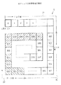
図2(a) は図1の光ディスク装置1の外観図であり、(b) は内部構成を示す図である。光ディスク装置1は、その筐体(ディスクエンクロージャ)10の中に、機構部11、固定光学部12、制御回路部13、可動光学部及びアクチュエータ14を備えており、機構部11によってこの筐体10内に出し入れされる光ディスクカートリッジ15内の光ディスク6を記録媒体としている。
【0023】
詳しい説明は省略するが、機構部11は、スピンドルモータ、ポジショナ、ヘッドアクチュエータ、バイアスマグネット、及び、スピンドルモータの上下移動機構を備えている。また、固定光学部12は、光学系、位置検出、及びレーザダイオード制御回路から構成されている。更に、制御回路部13は筐体10の外部に取り付けられており、SISIコネクタ、装置制御回路、データバッファとしてのキャッシュメモリ、及びSCSIコントーラ部から構成されている。
【0024】
図3は図2(a) ,(b) で説明した光ディスク装置1の内部構成を示すブロック図である。光ディスク装置1の筐体10内には前述のように、機構部11、固定光学部12、可動光学部及びアクチュエータ14、及び、光ディスク6がある。光ディスク装置1の筐体10の外側に設けられる制御回路部13には、ODC(光ディスクコントローラ)16、ODC16に接続し、MPU,ロジック回路,ROM,S−RAM等を備えた制御回路17、制御回路17に接続するDSP(デジタル信号プロセッサ)18、ODC16と制御回路17に接続されて筐体10内の装置を駆動するアンプ群19、および、ODC16に接続されたバッファメモリであるキャッシュメモリ(D−RAMで構成される)20がある。
【0025】
光ディスク装置1では、SCSIバス5と光ディスクカートリッジ15内のディスク媒体とのデータ転送を、キャッシュメモリ20を介してMPUが実行する、いわゆるキャッシュ制御が行われる。キャッシュメモリ20にデータを格納することができるので、光ディスク装置1の実効データ転送速度に依存することなく、イニシエータであるホストシステム3はSCSIバス5の高速データ転送能力を生かした効率の良い入出力処理を行うことができる。
なお、以後の説明における読み出し、転送、展開、管理等の動作は、特に記載しない限り前述のMPUが実行するものとする。
【0026】
キャッシュ制御について詳しく説明すると、ホストシステム3が光ディスク装置1に書込コマンドを発行した時、光ディスク装置1はキャッシュメモリ20に書込データを転送し、データ転送が終了した段階で書込コマンド終了を報告する。そして、光ディスク装置1は、SCSI動作と非同期に、書込処理や確認処理を行う。この結果、ホストシステム3から見た見かけ上の書込コマンド処理時間は短縮され、ホストシステム3の入出力特性が向上する。
【0027】
一方、ホストシステム3から光ディスク装置1に読出コマンドが発行された場合は、光ディスク装置1は、光ディスク6からのデータ読出コマンドの実効を終了した後、後続のデータブロックを自動的に読み出してキャッシュメモリ20に格納しておく。この動作は先読み動作と呼ばれる。従って、ホストシステム3からの次のコマンドが、先読みしてキャッシュメモリ20内に格納してあるデータを要求している時には、光ディスク6をアクセスすることなく、キャッシュメモリ20内のデータを転送することができるので、高速なシーケンシャルデータのアクセスが可能である。
【0028】
以上のようなキャッシュ制御におけるデータの読み出し制御において、ホストシステム3からの次のコマンドによる読み出しデータが、先読みしてキャッシュメモリ20内に格納してあるデータに一致することはヒットと呼ばれ、このヒット率が高い程、高速なシーケンシャルデータのアクセスが可能となる。
そこで、本発明では、キャッシュメモリ20内のデータバッファ領域を、図4に示すように、FAT部用データバッファ領域21、DIR部用データバッファ領域22、およびデータ部用データバッファ領域23の3つに分けている。このように、キャッシュメモリ20内のデータバッファ領域を3つに分ける理由は、図5に示すように、光ディスク6に螺旋状に形成された記憶領域には、論理ブロックアドレス(LBA)が0から始まるFAT部31と、これに続くDIR部32、及びデータ部33が存在するからである。
【0029】
そして、本発明では、ホストシステムが指示する論理ブロックアドレスがFAT部31のものであれば、読み出したデータをキャッシュメモリ20のFAT部用のデータバッファ領域21に対して展開を行い、DIR部32に対してならDIR部用のデータバッファ領域22に対してデータの展開を行う。また、ホストシステムが指示する論理ブロックアドレスがFAT部31とDIR部32のいずれにも当てはまらないようなら、読み出したデータをデータ部用のデータバッファ領域23に対して展開を行う。
【0030】
このように使用目的別にキャッシュメモリ20のデータバッファ領域21〜23を管理することにより、FAT部用データバッファ領域21とDIR部用データバッファ領域22には、ディスク媒体のFAT部31及びDIR部32のデータが必ず存在する。このため、光ディスク6のFAT部31とDIR部32に対するホストシステム3からの読み出し要求に対しては、これらのデータを一度読み出してキャッシュメモリ20の対応するデータバッファ領域21,22に格納しておけば、以後はキャッシュメモリ20からの転送と、データ部33からの読み出しのデータ転送動作のみですむ事となり、光ディスク装置1の性能が向上する。
【0031】
ここで、ホストコンピュータ3の一般的なOS(オペレーティングシステム)が、光ディスクカートリッジ15内の光ディスク6からデータを読み出す場合の過程を具体例を用いて説明する。
実施例として、光ディスク6には以下のようなファイルAとファイルBが記憶されており、これらファイルAとファイルBのデータを読み取る場合のキャッシュメモリ20の分割について説明する。
【0032】

(1)第1の実施例
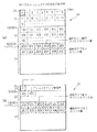
第1の実施例は、図6(a) に示すように、光ディスク装置1が保有するキャッシュメモリ20のデータバッファ領域を、バッファアドレス0h〜19999hのFAT部用データバッファ領域21、バッファアドレス20000h〜59999hのDIR部用データバッファ領域22、及びバッファアドレス60000h以降のデータ部用データバッファ領域23に分割している。この実施例は、キャッシュメモリ20のサイズが大きく、OSが使用するディスク媒体のFAT部31及びDIR部32と同サイズのデータバッファ領域21,22をキャッシュメモリ20内に確保することができ、しかもデータ部用のデータバッファ領域23もキャッシュメモリ20内に十分確保できる場合の実施例である。
【0033】
FAT部用データバッファ領域21とDIR部用データバッファ領域22には、光ディスク6のLBA(論理ブロックアドレス)に対応したバッファアドレスを割り振る。
この実施例では、図5に示したファイルAとファイルBの、FAT部31におけるLBA=0のデータがキャッシュメモリ20のFAT部用データバッファ領域21に格納され、DIR部32におけるLBA=100,101のデータがキャッシュメモリ20のDIR部用データバッファ領域22に格納される。そして、ファイルAのデータ部33におけるLBA=300〜304のデータと、LBA=306〜30Cのデータもデータ部用データバッファ領域23に格納することができる。この実施例ではデータ部用データバッファ領域23が一杯になった時には、新たなデータを記憶するバッファアドレスを記憶時期の古い情報のアドレス、又は、アクセス頻度の低い情報のアドレスからにすることができる。
(2)第2の実施例
第2の実施例は、図6(b) に示すように、光ディスク装置1が保有するキャッシュメモリ20のデータバッファ領域を、バッファアドレス0h〜4999hのFAT部用データバッファ領域21、バッファアドレス5000h〜9999hのDIR部用データバッファ領域22、及びバッファアドレス10000h以降のデータ部用データバッファ領域23に分割している。この実施例は、キャッシュメモリ20のサイズが小さく、光ディスク6のFAT部31とDIR部32に相当するデータサイズをキャッシュメモリ20のデータバッファ領域に確保することができない場合の実施例である。この場合でも、光ディスク6のFAT部31のデータを記憶するFAT部用データバッファ領域21と、DIR部32のデータを記憶するDIR部用データバッファ領域22とを持つことには変わりがなく、それぞれのサイズが第1の実施例に比べると縮小される。このため、光ディスク6のFAT部31とDIR部32のそれぞれに対して、キャッシュメモリ20のFAT部用データバッファ領域21とDIR部用データバッファ領域22は専用のバッファアドレスを持つことができない。従って、第2の実施例ではFAT部用データバッファ領域21とDIR部用データバッファ領域22の管理は、第1の実施例におけるデータ部用データバッファ領域23の管理と同様に処理する。
(3)第3の実施例
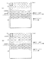
第3の実施例は、図7(a) に示すように、光ディスク装置1が保有するキャッシュメモリ20のデータバッファ領域を、バッファアドレス0h〜19999hのFAT部用データバッファ領域21、バッファアドレス20000h〜29999hのDIR部用データバッファ領域22、及びバッファアドレス30000h以降のデータ部用データバッファ領域23に分割している。第2の実施例は、キャッシュメモリ20のサイズが、第1の実施例のキャッシュメモリ20よりは小さいが、第2の実施例のキャッシュメモリ20よりは大きい場合の実施例である。従って、第2の実施例では、OSが使用する光ディスク6のFAT部31と同サイズのデータバッファ領域21はキャッシュメモリ20内に確保するようにしたが、光ディスク6のDIR部32に対しては、最小限のサイズのデータバッファ領域22をキャッシュメモリ20内に確保するようにし、残りのデータバッファ領域を全てデータ部用のデータバッファ領域23としてある。
【0034】
第3の実施例ではDIR部用データバッファ領域22の管理は、第1の実施例におけるデータ部用データバッファ領域23の管理と同様に処理する。
(4)第4の実施例
第4の実施例は、図7(b) に示すように、光ディスク装置1が保有するキャッシュメモリ20のデータバッファ領域を、バッファアドレス0h〜4999hのFAT部用データバッファ領域21、バッファアドレス5000h〜44999hのDIR部用データバッファ領域22、及びバッファアドレス45000h以降のデータ部用データバッファ領域23に分割している。第4の実施例も、キャッシュメモリ20のサイズが、第1の実施例のキャッシュメモリ20よりは小さいが、第2の実施例のキャッシュメモリ20よりは大きい場合の実施例である。従って、第4の実施例では、OSが使用する光ディスク6のDIR部32と同サイズのデータバッファ領域22はキャッシュメモリ20内に確保するようにしたが、光ディスク6のFAT部31に対しては、最小限のサイズのデータバッファ領域21をキャッシュメモリ20内に確保するようにし、残りのデータバッファ領域を全てデータ部用のデータバッファ領域23としてある。
【0035】
第4の実施例ではFAT部用データバッファ領域21の管理は、第1の実施例におけるデータ部用データバッファ領域23の管理と同様に処理する。
第2〜第4の実施例のように、キャッシュメモリ20のデータバッファ領域の大きさが十分に大きくない場合でも、読み出すファイルの容量が小さい場合は、第1の実施例と同様に、図5に示したファイルAとファイルBの、FAT部31におけるLBA=0のデータがキャッシュメモリ20のFAT部用データバッファ領域21に格納でき、DIR部32におけるLBA=100,101のデータがキャッシュメモリ20のDIR部用データバッファ領域22に格納できる。ファイルAのデータ部33におけるLBA=300〜304のデータと、LBA=306〜30Cのデータもデータ部用データバッファ領域23に格納することができる。
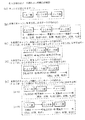
次に、以上説明した第1の実施例のようにキャッシュメモリ20内のデータバッファ領域が3つの領域に分割されている場合に、OSが光ディスク6に記憶されているファイルAを読み出そうとする場合の読み出し手順の一例について、図8〜図10のフローチャートを用いて説明する。ファイルAのデータを読み出そうとする場合には、最初にFAT31部のデータを読み出し、次にDIR部32のデータを読み出し、続いてデータ部33のデータを読み出す。よって、OSの読み出し手順をこの順に説明する。
【0036】
図8は光ディスク6のFAT部31のデータ読み出し手順を示すものである。ステップ801ではホストシステムからFAT部31の読み出し指示が有ったか否かを判定する。読み出し指示があった場合にはステップ802に進み、キャッシュメモリ20のFAT部用データバッファ領域21に有効データが有るか否かを判定する(図にはFAT部用データバッファ領域は単にFAT部と記載)。最初はFAT部用データバッファ領域21に有効データがないので、ステップ803に進み、光ディスク6のFAT部31を読み出してキャッシュメモリ20のFAT部用データバッファ領域21に、バッファアドレス0h番地から記憶し、続くステップ804においてFAT部用データバッファ領域21内のデータを転送する。
【0037】
ファイルAのFAT部31のデータは、図5で説明したように、光ディスク6のLBA=0hから記録されている。そして、光ディスク装置1が保有するキャッシュメモリ20には、光ディスク6のFAT部31のデータの記憶用に専用に割り振られたバッファアドレス0h番地が存在する。そこで、光ディスク装置1は、光ディスク6の記憶領域内のLBA=0hからブロック数=1hだけ読み出し、これをキャッシュメモリ20のFAT部用データバッファ領域21の0h番地から展開し、展開終了後にホスト側に転送する。FAT部用データバッファ領域21に展開されたデータはそのまま保持され有効となる。
【0038】
ステップ804でFAT部用データバッファ領域21に展開されたデータを転送した後はステップ805に進み、光ディスク6のFAT部31のデータ読み出しが完了したか否かを判定する。光ディスク6のFAT部31のデータ読み出しが完了していない場合はステップ806に進み、ホスト側からの次の指示があるか否かを判定する。そして、次の指示がない場合には、光ディスク装置1はステップ807に進み、光ディスク6のFAT部31の次のLBAの1ブロック分のデータを先読みし、キャッシュメモリ20のFAT部用データバッファ領域21の続きのバッファアドレスから記憶する。
【0039】
光ディスク6のFAT部31の次のLBAの1ブロック分のデータを先読みしてFAT部用データバッファ領域21に記憶した後はステップ805に戻り、再度光ディスク6のFAT部31のデータ読み出しが完了したか否かの判定を行い、以後はステップ805で光ディスク6のFAT部31のデータ読み出しが完了した場合とステップ806でホスト側からの次の指示が来た場合の除き、光ディスク6のFAT部31の次のLBAの1ブロック分のデータを更に先読みしてFAT部用データバッファ領域21の続きのバッファアドレスから記憶する動作を繰り返す。
【0040】
一方、ステップ805で光ディスク6のFAT部31のデータ読み出しが完了したと判定した場合と、ステップ806でホスト側から次の指示があったと判定した場合はステップ801に戻る。そして、ステップ801においてホスト側からの指示がFAT部の読み出し指示か否かを判定し、FAT部以外の読み出し指示の場合はステップ808に進む。
【0041】
図9は光ディスク6のDIR部32のデータ読み出し手順を示すものである。ステップ808ではホストシステムからDIR部32の読み出し指示が有ったか否かを判定する。読み出し指示があった場合にはステップ809に進み、キャッシュメモリ20のDIR部用データバッファ領域22に有効データが有るか否かを判定する(図にはDIR部用データバッファ領域は単にDIR部と記載)。最初はDIR部用データバッファ領域22に有効データがないので、ステップ810に進み、光ディスク6のDIR部32を読み出してキャッシュメモリ20のDIR部用データバッファ領域22に、バッファアドレス20,000h番地から記憶し、続くステップ811においてDIR部用データバッファ領域22内のデータを転送する。
【0042】
ファイルAのDIR部32のデータは、図5で説明したように、光ディスク6のLBA=100hからブロック数=2hだけ記録されている。そして、光ディスク装置1が保有するキャッシュメモリ20には、光ディスク6のDIR部32のデータの記憶用に専用に割り振られたバッファアドレス20,000h番地が存在する。そこで、光ディスク装置1は、光ディスク6の記憶領域内のLBA=100hからブロック数=2hだけ読み出し、これをキャッシュメモリ20のDIR部用データバッファ領域22の20,000h番地から展開し、展開終了後にホスト側に転送する。DIR部用データバッファ領域22に展開されたデータはそのまま保持され有効となる。
【0043】
ステップ811でDIR部用データバッファ領域22に展開されたデータを転送した後はステップ812に進み、光ディスク6のDIR部32のデータ読み出しが完了したか否かを判定する。光ディスク6のDIR部32のデータ読み出しが完了していない場合はステップ813に進み、ホスト側からの次の指示があるか否かを判定する。そして、次の指示がない場合には、光ディスク装置1はステップ814に進み、光ディスク6のDIR部32の次のLBAの1ブロック分のデータを先読みし、キャッシュメモリ20のDIR部用データバッファ領域22の続きのバッファアドレスから記憶する。
【0044】
光ディスク6のDIR部32の次のLBAの1ブロック分のデータを先読みしてDIR部用データバッファ領域22に記憶した後はステップ812に戻り、再度光ディスク6のDIR部32のデータ読み出しが完了したか否かの判定を行い、以後はステップ812で光ディスク6のDIR部32のデータ読み出しが完了した場合とステップ813でホスト側からの次の指示が来た場合の除き、光ディスク6のDIR部32の次のLBAの1ブロック分のデータを更に先読みしてDIR部用データバッファ領域22の続きのバッファアドレスから記憶する動作を繰り返す。
【0045】
一方、ステップ812で光ディスク6のDIR部32のデータ読み出しが完了したと判定した場合と、ステップ813でホスト側から次の指示があったと判定した場合はステップ808に戻る。そして、ステップ808においてホスト側からの指示がDIR部32の読み出し指示か否かを判定し、DIR部32以外の読み出し指示の場合はステップ815に進む。
【0046】
図10は目的である光ディスク6のデータ部33のデータ読み出し手順を示すものである。ステップ815ではホストシステムからデータ部33の読み出し指示が有ったか否かを判定する。読み出し指示があった場合にはステップ816に進み、キャッシュメモリ20のデータ部用データバッファ領域23に有効データが有るか否かを判定する(図にはデータ部用データバッファ領域は単にデータ部と記載)。最初はデータ部用データバッファ領域23に有効データがないので、ステップ817に進み、バッファに空きがあるか否か、即ちデータ部用データバッファ領域23に空きがあるか否かを判定し、空きがある場合にはステップ818に進んでバッファの空いている所にデータを読み出してステップ820に進む。一方、ステップ817でバッファに空きがないと判定した場合はステップ819に進み、光ディスク6のデータ部33を読み出してキャッシュメモリ20のデータ部用データバッファ領域23の、最も古いアクセスカウンタ値のアドレスに読み出して記憶し、続くステップ820においてデータ部用データバッファ領域23内のデータを転送する。
【0047】
ファイルAのデータ部33のデータは、図5で説明したように、光ディスク6のLBA=300hからブロック数=5hだけ記録されている。そして、光ディスク装置1が保有するキャッシュメモリ20には、光ディスク6のデータ部33のデータの記憶用に専用に割り振られたバッファアドレスとして60000h番地以降が存在する。ここで、データ部33のデータ量はFAT部31やDIR部32に記録されているデータ量よりも遙に多く、通常はキャッシュメモリ20のデータ部用データバッファ領域23の容量よりも大きい。そこで、光ディスク装置1が保有するキャッシュメモリ20のデータ部用データバッファ領域23は、FAT部用データバッファ領域21やDIR部用データバッファ領域22と異なり、光ディスク6のデータ部33のアドレスに対応していない。即ち、データ部用データバッファ領域23は光ディスク6上のデータに対して専用のアドレスが存在するのではない。
【0048】
このようなデータ部用データバッファ領域23は、図3で説明したアクセスカウンタにより、最も古いアクセスカウンタ値のバッファアドレスを展開先と決め、有効か無効を示す情報を持つようになっている。従って、データ部用データバッファ領域23に光ディスク6のデータ部33のデータを記憶する場合には、アクセスカウンタにアドレスの記録を残しておき、最も古いアクセスカウンタ値のバッファアドレスから上書き記憶し、アクセスカウンタを更新することが行われる。ファイルAのデータ部33のデータを始めて記憶する場合は、データ部用データバッファ領域23は全て無効である為、光ディスク6の記録領域内のLBA=300hからブロック数=5hを読み出し、データ部用データバッファ領域23の60000h番地から展開した後に転送する。データ部用データバッファ領域23に展開されたデータはそのまま保持され有効となる。
【0049】
ステップ820でデータ部用データバッファ領域23に展開されたデータを転送した後はステップ821に進み、光ディスク6のファイルAのデータ部33のデータ読み出しが完了したか否かを判定する。ファイルAのデータ部33のデータ読み出しが完了していない場合はステップ822に進み、ホスト側からの次の指示があるか否かを判定する。そして、次の指示がない場合には、光ディスク装置1はステップ823に進み、ファイルAのデータ部33の次のLBAの1ブロック分のデータを先読みし、キャッシュメモリ20のデータ部用データバッファ領域23の最も古いアクセスカウンタ値のバッファアドレスから記憶する。
【0050】
ファイルAのデータ部33の次のLBAの1ブロック分のデータを先読みしてデータ部用データバッファ領域23に記憶した後はステップ821に戻り、再度ファイルAのデータ部33のデータ読み出しが完了したか否かの判定を行い、以後はステップ821でファイルAのデータ部33のデータ読み出しが完了した場合とステップ822でホスト側からの次の指示が来た場合の除き、ファイルAのデータ部33の次のLBAの1ブロック分のデータを更に先読みしてデータ部用データバッファ領域23の最も古いアクセスカウンタ値のバッファアドレスから記憶する動作を繰り返す。
【0051】
一方、ステップ821でファイルAのデータ部33のデータ読み出しが完了したと判定した場合と、ステップ822でホスト側から次の指示があったと判定した場合はステップ815に戻る。そして、ステップ815においてホスト側からの指示がファイルAのデータ部33の読み出し指示か否かを判定し、データ部33以外の読み出し指示の場合はこのルーチンを終了する。
【0052】
このようにしてファイルAのデータを読み出す場合、3回の媒体アクセス動作を行う事になる。
なお、第2〜第4の実施例のように、キャッシュメモリ20のFAT部用データバッファ領域21またはDIR部用データバッファ領域22の大きさが小さく、読み出し時にFAT部用データバッファ領域21またはDIR部用データバッファ領域22の容量を越えてしまう場合には、FAT部用データバッファ領域21またはDIR部用データバッファ領域22の記憶領域を前述のデータ部用データバッファ領域23のようにアクセスカウンタで管理する。そして、FAT部用データバッファ領域21またはDIR部用データバッファ領域22の記憶領域が一杯となり、データの展開が不可能になるとアクセスカウンタの値を参照し、アクセスカウンタが低い値、または低い値が複数個存在する場合は一番古いバッファアドレス上にディスク媒体からデータを読み出して展開し、新しく展開したデータのアクセスカウンタを設定する。有効データと同一な読み出しが行える場合はアクセスカウンタを更新し、有効を継続することができる。
【0053】
この後、OSがファイルBのデータ部のデータを読み出す場合には、以上述べた手順と同様に、最初にFAT部31のデータを読み出す。ところが、読み出そうとするFAT部31のデータのLBA=0hからのブロック数=1hがファイルAのデータを読み出した時のFAT部用データバッファ領域21上の0h番地に存在する。このため、ファイルBのFAT部31のデータは、光ディスク6の読み出し実動作を伴うことなく、キャッシュメモリ20のFAT部用データバッファ領域21から転送することができる。
【0054】
続いて、ファイルBのDIR部32のデータを読み出すが、これも前回有効としたキャッシュメモリ20のDIR部用データバッファ領域22の20000h番地上に存在する為、キャッシュメモリ20のDIR部用データバッファ領域22から転送することができる。最後に目的であるファイルBのデータ部33のデータが読み出される。ファイルBのデータは、データ部用データバッファ領域23の上に該当するデータが存在しない為、光ディスク6の記録領域内のLBA=306hからブロック数=7hを読み出し、データ部用データバッファ領域23の前回展開した続きのバッファアドレスに展開してから転送する。展開されたデータはデータバッファ上で保持され有効になる。この時、前回展開された60000h番地のアクセスカウンタ値は1つ古いものとなる。このようにファイルAに続いてファイルBのファイルデータを読み出す場合は、1回の光ディスク6の読み出し実動作だけで済むことになる。
【0055】
また、OSがその他のデータを読み出す場合にキャッシュメモリ20上にあるFAT部用データバッファ領域21、DIR部用データバッファ領域22内のデータを使用可能であれば、ファイルBに対する読み出し動作と同様の動作を行うだけで済む。また、キャッシュメモリ20上にあるFAT部用データバッファ領域21、DIR部用データバッファ領域22内のデータを使用可能でない場合には、ファイルAに対する読み出し動作と同様の動作を実行する。そして、ファイルに対する読み取り処理が繰り返されると、キャッシュメモリ20上にあるFAT部用データバッファ領域21、DIR部用データバッファ領域22内に有効データが増えていき、やがてOSが使用する光ディスク6のFAT部31、DIR部32のデータが全てキャッシュメモリ20に格納されて有効となり、OSからの全ての光ディスク6のFAT部31、DIR部32の読み取り動作がバッファ転送だけで良くなり、光ディスク装置1の性能が向上する。
【0056】
次に、本発明のキャッシュメモリ20のデータバッファの分割方法の変形実施例を説明する。
(5)第5の実施例
第5の実施例は、図11(a) に示すように、光ディスク装置1が保有するキャッシュメモリ20のデータバッファ領域を、バッファアドレス0h〜19999hのFAT部用データバッファ領域21と、バッファアドレス20000h以降のDIR部データ部兼用データバッファ領域24に分割している。この実施例も、キャッシュメモリ20のサイズが小さく、光ディスク6のFAT部31とDIR部32に相当するデータサイズをキャッシュメモリ20のデータバッファ領域に確保することができない場合の実施例である。
【0057】
第5の実施例は前述の第1から第4の実施例と異なり、キャッシュメモリ20のFAT部用データバッファ領域21のみを光ディスク6のFAT部31と同一なサイズを持つ専用のデータバッファ領域として確保したものである。第5の実施例では光ディスク6のDIR部32とデータ部33については、キャッシュメモリ20内にDIR部データ部兼用データバッファ領域24を確保し、これを共通に使用するようにしている。
【0058】
このため、光ディスク6のとDIR部32とデータ部33はそれぞれキャッシュメモリ20のDIR部データ部兼用データバッファ領域24内に専用のバッファアドレスを持つことができない。従って、第5の実施例ではDIR部データ部兼用データバッファ領域24の管理は、第1の実施例におけるデータ部用データバッファ領域23の管理と同様に処理する。
(6)第6の実施例
第6の実施例は、図11(b) に示すように、光ディスク装置1が保有するキャッシュメモリ20のデータバッファ領域を、バッファアドレス0h〜39999hのDIR部用データバッファ領域22と、バッファアドレス40000h以降のFAT部データ部兼用データバッファ領域25に分割している。この実施例も、キャッシュメモリ20のサイズが小さく、光ディスク6のFAT部31とDIR部32に相当するデータサイズをキャッシュメモリ20のデータバッファ領域に確保することができない場合の実施例である。
【0059】
第6の実施例は第5の実施例と同様に、キャッシュメモリ20のDIR部用データバッファ領域22のみを光ディスク6のDIR部32と同一なサイズを持つ専用のデータバッファ領域として確保したものである。第6の実施例では光ディスク6のFAT部31とデータ部33については、キャッシュメモリ20内にFAT部データ部兼用データバッファ領域25を確保し、これを共通に使用するようにしている。
【0060】
このため、光ディスク6のFAT部31とデータ部33はそれぞれキャッシュメモリ20のFAT部データ部兼用データバッファ領域25内に専用のバッファアドレスを持つことができない。従って、第6の実施例ではFAT部データ部兼用データバッファ領域25の管理は、第1の実施例におけるデータ部用データバッファ領域23の管理と同様に処理する。
【0061】
第5の実施例において、OSがファイルAのデータ部33のデータを読み出そうとする場合には、最初にFAT部31のデータを読み出す。ファイルAのデータのFAT部はLBA=0hを使用している。光ディスク装置1が保有するFAT部用データバッファ領域21にはLBA=0h専用に割り振られたバッファアドレス0h番地が存在し、最初は無効を示している。この場合、光ディスク装置1はまず、光ディスク6の記憶領域内のLBA=0hからブロック数=1hのFAT部31のデータを読み出し、FAT部用データバッファ領域21の0h番地上に展開してから転送する。展開されたデータはデータバッファ上で保持され有効となる。
【0062】
続いて、光ディスク装置1はDIR部32のデータを読み出す。ファイルAのデータのDIR部32はLBA=100hを使用している。光ディスク装置1が保有するキャッシュメモリ20のDIR部データ部兼用データバッファ領域24にはLBA=100hのDIR部データが存在しないので、光ディスク装置1は光ディスク6の記憶領域内のLBA=100hからブロック数=2hのDIR部32のデータを読み出し、DIR部データ部兼用データバッファ領域24のバッファアドレス20000h番地に展開してから転送する。展開されたデータはデータバッファ上で保持され有効となり、アクセスカウンタに最新値をセットする。
【0063】
最後に目的であるデータ部のデータを読み出す。ファイルAのデータのデータ部33はLBA=300hを使用している。これはDIR部32と同様に光ディスク装置が保有するキャッシュメモリ20のDIR部データ部兼用データバッファ領域24には該当するデータが存在しないので、光ディスク装置1は光ディスク6の記憶領域内のLBA=300hからブロック数=5hを読み出し、これをDIR部データ部兼用データバッファ領域24のDIR部32を展開した続きの20400h番地に展開して転送する。展開されたデータはデータバッファ上で保持され有効となり、アクセスカウンタに最新値をセットする。この時、前回展開された20000h番地のアクセスカウンタ値は1つ古いものとなる。このようにしてファイルAのファイルデータを読み出す場合は、3回の媒体アクセス動作を行う事になる。
【0064】
この後、OSが上記ファイルBのデータ部のデータを読み出す場合には、上記手順と同様に最初に光ディスク6のFAT部31のデータを読み出す。ところが、読み出そうとするFAT部データのLBA=0hからブロック数=1hのデータは、キャッシュメモリ20のFAT部用データバッファ領域21の0番地に存在する。このため、光ディスク装置1は光ディスク6からの読み出しを行うことなく、このデータをキャッシュメモリ20のFAT部用データバッファ領域21から転送する。
【0065】
続いて、DIR部32のデータを読み出すが、これも前回有効としたキャッシュメモリ20のDIR部データ部兼用データバッファ領域24の20000h番地上に存在する為、キャッシュメモリ20から転送する。最後に目的であるデータ部のデータを読み出す。これはDIR部データ部兼用データバッファ領域24に該当するデータが存在しない。このため、光ディスク装置1は光ディスク6の記憶領域のデータ部33からファイルBのデータを読み出し、これをDIR部データ部兼用データバッファ領域24の前回展開した続きのバッファアドレス20E00h番地に展開してから転送する。展開されたデータはDIR部データ部兼用データバッファ領域24上で保持され有効になる。この時、前回展開された10400h番地及び前々回展開された20000h番地のアクセスカウンタ値は1つ古いものとなる。このようなファイルAに続いてファイルBのファイルデータを読み出す場合は、1回の実動作だけで済むことが分かる。
【0066】
また、OSがその他のデータを読み出す場合でも、キャッシュメモリ20上に記憶されている光ディスク6のFAT部31とDIR部32のデータが使用可能であれば、光ディスク6にアクセスすることなく、これらのデータをキャッシュメモリ20から転送することができる。
これ以降、読み取り処理が繰り返されると、FAT部用データバッファ領域21に有効データが増えていき、やがてOSが使用する光ディスク6のFAT部31のデータが全てFAT部用データバッファ領域21上に有効となるので、光ディスク6のFAT部31の読み取り動作は不要となり、全てキャッシュメモリ20から転送することができる。また、光ディスク6のDIR部32、データ部33のデータの読み出しに関しては、キャッシュメモリ20のDIR部データ部兼用データバッファ領域24が一杯となり、データの展開が不可能になるとアクセスカウンタの値を参照し、アクセスカウンタ値が低い値もしくは低い値が複数個存在する場合は一番古いバッファアドレス上に光ディスク6から読み出したデータを展開し、新しく展開したデータのアクセスカウンタを設定する。有効データと同一な読み出しが行える場合はアクセスカウンタを更新し、有効を継続することができる。OSの使用頻度の高いファイルがキャッシュメモリ20上に残るため、磁気ディスク装置1の光ディスク6へのアクセス回数が減り、磁気ディスク装置1の性能が向上する。
【0067】
第6の実施例において、OSがファイルAのデータ部33のデータを読み出そうとする場合は、光ディスク6のFAT部31から読み出したデータがFAT部データ部兼用データバッファ領域25に、データ部33のデータと共通に記憶され、DIR部32から読み出したデータが専用のDIR部用データァバッファ領域22に記憶される点が、第5の実施例と異なるだけであるので、その説明を省略する。
【0068】
図12は、光ディスク媒体からのデータ読み出し時に、FAT部とDIR部とデータ部とが全てキャッシュメモリに存在した場合の本発明の方法による読み出し時間の短縮を、従来のデータ読み出し時間と比較して示す説明図である。図におけるファーム処理は光ディスク装置の処理である。
従来は、FAT部、DIR部、データ部の読み出しコマンドがホスト(OS)から来る毎に、光ディスク装置はヘッドのシーク指示をし、ヘッドが光ディスク上の読み出し位置に移動されるとシーク完了指示が発行され、その後、光ディスクのリード指示でデータが読み取られ、リードが完了してデータがキャッシュメモリに読み込まれた後に、光ディスク装置からホストへデータが転送されていた。
【0069】
これに対して、本発明の方法によれば、光ディスクからのデータ読み出し時に、FAT部とDIR部とデータ部とが全てキャッシュメモリに存在した場合は、FAT部とDIR部とデータ部への各リードコマンドの後に、キャッシュメモリからデータ転送を行うことができるので、光ディスクへのヘッドのアクセスが不要となる。この結果、FAT部の読み出し時間、DIR部の読み出し時間、及びデータ部の読み出し時間が全て短縮され、短縮された時間の合計がT0となり、時間T0の時間短縮が図れる。
【0070】
図13は、光ディスクからのデータ読み出し時に、FAT部とDIR部とがキャッシュメモリに存在した場合の本発明の方法による読み出し時間の短縮を、従来のデータ読み出し時間と比較して示す説明図である。
この場合、本発明の方法によれば、データ部の読み出し時間だけは従来のデータ部の読み出し時間と同じになるが、FAT部の読み出し時間とDIR部の読み出し時間が従来よりも短くなる。この結果、FAT部の読み出し時間とDIR部の読み出し時間において読み出し時間が短縮され、短縮された時間の合計がT1となり、時間T1の時間短縮が図れる。
【0071】
図14は、光ディスクからのデータ読み出し時に、FAT部のデータのみがキャッシュメモリに存在した場合の本発明の方法による読み出し時間の短縮を、従来のデータ読み出し時間と比較して示す説明図である。
この場合、本発明の方法によれば、DIR部の読み出し時間とデータ部の読み出し時間とが従来のデータ部の読み出し時間と同じになるが、FAT部の読み出し時間が従来よりも短くなる。この結果、FAT部の読み出し時間が時間T2だけ短縮され、時間T2の時間短縮が図れる。
【0072】
図15は、光ディスクからのデータ読み出し時に、DIR部のデータのみがキャッシュメモリに存在した場合の本発明の方法による読み出し時間の短縮を、従来のデータ読み出し時間と比較して示す説明図である。
この場合、本発明の方法によれば、FAT部の読み出し時間とデータ部の読み出し時間とが従来のデータ部の読み出し時間と同じになるが、DIR部の読み出し時間が従来よりも短くなる。この結果、DIR部の読み出し時間が時間T3だけ短縮され、時間T3の時間短縮が図れる。
【0073】
図16は、光ディスクからのデータ読み出す時の色々な場合のデータ読み出し時間を、まとめて従来のデータ読み出し時間と比較して示す説明図である。データの読み出し時には、(a) に示すように、ホストコンピュータはFAT部、DIR部、及びデータ部の全てのデータを読み出す必要がある。この場合、(b) に示す従来のキャッシュ制御方式によれば、FAT部、DIR部、及びデータ部の全ての読み出しにおいて読み出し、記憶、転送の実動作が必要になり、全てが完了する時間は長くなる。
【0074】
これに対して、(c) 〜(e) が本発明によるキャッシュ制御方式によるデータの読み出し処理を示している。(c) が図12で説明した場合と同じ状態を示しており、FAT部、DIR部、及びデータ部のデータが全てキャッシュメモリ内にあって、データは全てキャッシュメモリからの転送のみで済む場合である。この場合が最も読み出し時間が短縮できる。(d) が図13で説明した場合と同じ状態を示しており、FAT部とDIR部のデータがキャッシュメモリ内にあって、これらのデータはキャッシュメモリから転送できる場合である。この場合は(c) の場合に次いで読み出し時間が短縮できる。(e) はFAT部とDIR部のデータのいずれか一方がキャッシュメモリ内にあって、そのデータはキャッシュメモリから転送できる場合である。(e-1) が図14で説明した場合と同じ状態を示しており、(e-2) が図15で説明した場合と同じ状態を示している。これらの場合のように、FAT部とDIR部のデータのいずれか一方のみがキャッシュメモリ内にあった場合でも、従来のキャッシュ制御方式におけるデータ読み出し時間よりも読み出し時間を短縮できる。
【0075】
なお、以上説明した実施例では、記憶装置として光ディスク装置の例を説明しているが、本発明の方法における記憶装置は光ディスク装置に限定されるものではなく、記憶装置における記憶媒体とのデータの転送速度が、ホストコンピュータ側のデータの転送速度よりも遅いような記憶装置に対して有効に適用することができる。
【0076】
【発明の効果】
以上説明したように、本発明の記憶装置におけるデータバッファの管理方法によれば、FAT部、DIR部のキャッシュヒット率が向上する為、記憶媒体からのデータの読み出し、読み出したデータのデータバッファへの記憶、及びデータバッファからのデータの転送の実動作時間が縮小され、処理速度が向上する。その結果、データ部を読み出す場合の一連の処理速度が向上する。
【図面の簡単な説明】
【図1】データバッファを備えた記憶装置が使用されるシステムの構成例を示すブロック回路図である。
【図2】 (a) は図1の光ディスク装置の外観図であり、(b) は図1の光ディスク装置の内部構成を示す図である。
【図3】図2(a) ,(b) の光ディスク装置の内部構成を示すブロック図である。
【図4】図3のキャッシュメモリの本発明における分割の一例を示す説明図である。
【図5】光ディスクの記憶領域の構成を示す説明図である。
【図6】 (a) は図4のキャッシュメモリの分割の第1の実施例を示すブロック図、(b) は図4のキャッシュメモリの分割の第2の実施例を示すブロック図である。
【図7】 (a) は図4のキャッシュメモリの分割の第3の実施例を示すブロック図、(b) は図4のキャッシュメモリの分割の第4の実施例を示すブロック図である。
【図8】本発明の記憶装置におけるデータバッファの管理方法のデータ読み出し手順を示すフローチャートの一部である。
【図9】本発明の記憶装置におけるデータバッファの管理方法のデータ読み出し手順を示すフローチャートの一部である。
【図10】本発明の記憶装置におけるデータバッファの管理方法のデータ読み出し手順を示すフローチャートの一部である。
【図11】 (a) は図4のキャッシュメモリの分割の第5の実施例を示すブロック図、(b) は図4のキャッシュメモリの分割の第6の実施例を示すブロック図である。
【図12】記憶媒体からのデータ読み出し時にFAT部とDIR部とデータ部とが全てキャッシュメモリに存在した場合の読み出し時間の短縮を、従来のデータ読み出しと比較して示す説明図である。
【図13】記憶媒体からのデータ読み出し時にFAT部とDIR部とがキャッシュメモリに存在した場合の読み出し時間の短縮を、従来のデータ読み出しと比較して示す説明図である。
【図14】記憶媒体からのデータ読み出し時にFAT部のみがキャッシュメモリに存在した場合の読み出し時間の短縮を、従来のデータ読み出しと比較して示す説明図である。
【図15】記憶媒体からのデータ読み出し時にDIR部のみがキャッシュメモリに存在した場合の読み出し時間の短縮を、従来のデータ読み出しと比較して示す説明図である。
【図16】記憶媒体からのデータ読み出す時の色々な場合のデータ読み出し時間を比較して示す説明図である。
【符号の説明】
1…光ディスク装置
3…ホストシステム
4…ホストアダプタ
5…SCSIバス
6…光ディスク
12…固定光学部
13…制御回路部
14…可動光学部及びアクチュエータ
15…光ディスクカートリッジ
17…制御回路
20…キャッシュメモリ
21…FAT部用データバッファ領域
22…DIR部用データバッファ領域
23…データ部用データバッファ領域
24…DIR部データ部兼用データバッファ領域
25…FAT部データ部兼用データバッファ領域
31…FAT部
32…DIR部
33…データ部[0001]
BACKGROUND OF THE INVENTION
The present invention relates to a method for managing a data buffer in a storage device, and more particularly, to a method for managing a data buffer held by an optical disk device in an operating system (hereinafter referred to as OS) of a host computer using the optical disk device as a storage device.
[0002]
Conventionally, in a file system using an optical disk device, the read / write speed of the optical disk device is slower than the processing speed of the host computer (for example, when the operation clock of the host computer is 200 MHz, the operation clock of the optical disk device is 25 MHz). Therefore, when the data transfer speed is matched with the data reading / writing speed of the optical disk apparatus, there is a problem that the processing capability of the host computer is lowered.
[0003]
Therefore, when the optical disk device is used by being connected to the host computer, a data buffer called a cache memory having a high data transfer rate is built in the optical disk device, and the command or data from the host computer is later By temporarily storing what is likely to be used in the cache memory, the processing capacity of the host computer has been improved. This cache memory is efficient because the host computer OS can move another task if the normal end is reported by receiving all data and reporting normal end. Control in which data once stored in the cache memory is used later is called cache control. The cache control is performed by the firmware of the optical disk apparatus, that is, the ROM program in the MPU.
[0004]
This cache control will be described in more detail.SkWhen data is written to the apparatus, the data is once written to a cache memory in the optical disk apparatus, and the data in the cache memory is slowly written to the optical disk. On the other hand, when data is read from the optical disk device, the data read from the optical disk is transferred to the cache memory after being written once. However, when data is first read from the optical disk device, there is no data in the cache memory, so the data transfer speed becomes the read speed of the optical disk device. When reading one file in response to a request from the OS side, one sector is read by the first command. Since the next command issued from the OS is likely to read the next sector (data written immediately after it), the optical disk apparatus side will return to the next command when one command comes and returns normal termination to the OS side. Before the data arrives, data reading of the next sector is started and stored in the cache memory. If the data stored in the cache memory matches (hits) the data read by the next command, the stored data can be transferred from the cache memory.
[0005]
However, if the read sector indicated by the next command is different from the sector stored in the cache memory in advance (when the sector does not hit), it takes another processing time to specify the sector indicated by the optical disc apparatus. Since the data is read out, the efficiency is low. Therefore, it is desired to improve the hit rate of data stored in advance in the cache memory when data is read from the optical disk device.
[0006]
[Prior art]
Information handled by computers includes both programs and data, but to facilitate the organization and work of storing, reading, searching, and correcting these programs and data, a program and data are a unit of information (this is Each file (called a file) is named and processed. The OS of the host computer performs data management on the storage area held by the storage device by using a unique control method for all the storage devices. There are various control methods, but data is managed with at least the following three parts.
[0007]
(1) Search table section (File Allocation Table section, hereinafter referred to as FAT section)
(2) Directory part (Directory part, hereinafter referred to as DIR part), and
(3) Data section
The FAT section stores the address of the next sector of the file stored across a plurality of sectors of the disk medium of the optical disk apparatus, and the DIR section stores the start address and file name of the file. The data portion stores data.
[0008]
When the OS tries to read the file data, it first reads information about the data part from the FAT part and the DIR part, and reads data from the data part based on the read information. That is, when trying to read data from the data part, it is necessary to read the FAT part and the DIR part.
[0009]
[Problems to be solved by the invention]
However, the conventional cache control method is not aware of the reading procedure of the FAT unit, DIR unit, and data unit from the cache memory, and randomly determines the FAT unit, DIR unit, and data according to the OS read instruction. Since the data read from the disk medium is stored in the cache memory, and the data following the data read in the previous instruction is pre-read and stored in the cache memory until the next instruction is received, the data part is distributed. In such a case, there is a problem that the probability that the FAT part and the DIR part exist in the cache memory is low.
[0010]
This problem will be described in detail. In the conventional technique, the areas for storing the FAT part, the DIR part, and the data part are not divided in the cache memory. After the data of the first sector of the section is read, the data after the next sector of the FAT section is read and stored in the cache memory. However, if the next read command is not the FAT part but the data part, the data of the sector having the data part is overwritten and stored on the data of the FAT part that has been prefetched, and then the next sector of the data part is stored. Since the data is read and stored, the prefetched data of the FAT section is crushed. Therefore, even if a FAT section read command is issued after this, there is no data in the FAT section already in the cache memory, and the FAT section does not hit. The same applies to the DIR part and the data part.
[0011]
Therefore, an object of the present invention is to perform data management on a data buffer held by a storage device such as an optical disk device by a plurality of types of data, and to read each data in advance when reading data from the storage medium. In the storage device stored in the buffer, by managing the storage area of the data buffer, the probability that the data to be read is present on the data buffer at the time of data reading without erasing a plurality of different types of pre-read data It is to provide a data buffer management method in a high storage device.
[0012]
[Means for Solving the Problems]
The features of the present invention that achieve the above object will be described below as first to eighth inventions.
According to a first aspect of the present invention, there is provided a data buffer for temporarily storing data to be stored in a disk medium or data read from the disk medium, and the disk medium stores a first data for storing each data of a file which is an information unit. At least a first information storage unit, a second information storage unit that is an index table indicating a storage location of a file, and a third information storage unit that is a list of files. A method of managing a data buffer in a storage device that reads and writes desired data according to information in a storage unit, the storage region of the data buffer being at least a storage region of the first information and a storage unit of a second information The boundary address of each storage area is fixed and divided so that there is a storage area for the second information and a storage area for the third information that match the storage capacity. Come, when the storage area of the first information when reading data from the disk medium becomes fullBased on access counter valueRemember the data,When reading the second information from the second information storage unit and storing it in the second information storage area,Until all data stored in the second information storage unit is read from the second information storage unit or another data read instruction is receivedFrom the second information storage unitRead dataTheSecond information storage area secondOf informationThe data stored in the address corresponding to the address of the storage unit and the data read from the storage unit of the third information are stored and held in the storage area of the third information.
[0013]
According to a second invention, in the first invention, the storage capacity of the third information storage area of the data buffer is matched with the storage capacity of the third information storage section of the disk medium,When the third information is read from the third information storage unit and stored in the third information storage area,Until the reading of all information stored in the third information storage unit is completed from the third information storage unit or another data read instruction is issuedFrom the third information storage unitRead dataTheThirdOf informationStorage area thirdOf informationThe information is stored and held at an address corresponding to the address of the storage unit.
[0014]
According to a third aspect of the present invention, there is provided a data buffer for temporarily storing data to be stored in a disk medium or data read from the disk medium at a speed not different from the operation speed of the host. A first information storage unit for storing each of the data, a second information storage unit that is an index table indicating the storage location of the file, and a third information storage unit that is the file list information Is a data buffer management method in a storage device that reads and writes desired data according to information in each storage unit, and has a large storage capacity with a fixed boundary address in the storage area of the data buffer An area with a smaller storage capacity that is divided into two areas, an area and a smaller area, and the storage capacity of the second information storage unit is the same as the disk The area of the second information storage unit of the body is a dedicated storage area, and the area with the larger storage capacity is the data of the third information storage section of the disk medium and the storage section of the first information. As a common storage area for data, when reading data from disk media,When reading the second information from the storage unit of the second information and storing it in an area with a small storage capacity of the data buffer,The data in the second information storage unit of the disk medium is stored in the data buffer until the reading of all the information stored in the second information storage unit is completed or another data read instruction is received. Second in a small areaOf informationThe data stored in the address corresponding to the address of the storage unit is held and the data read from the storage unit of the first information and the data read from the storage unit of the third information use a large storage area in common. When the area with the large storage capacity is full, the read data is stored.Based on access counter valueIt is characterized in that it is stored and held.
[0015]
According to a fourth invention, in any one of the first to third inventions, when the storage area of the data buffer becomes full, the buffer address for storing new data is set to the oldest access counter value.HaveFrom the address.
According to a fifth invention, in any one of the first to third inventions, when the storage area of the data buffer becomes full, the buffer address for storing new data is set to the lowest access counter value.HaveFrom the address.
[0016]
6thThe invention of the first inventionThirdIn any one of the inventions, the storage device is an optical disk device.
7thThe invention of6thIn the invention, the first information storage unit is a data unit, the second information storage unit is an index table unit, and the third information storage unit is a directory unit.
[0017]
8thThe invention of7thIn this invention, the data buffer is a cache memory.
In the present inventionAccording to the present invention, the storage area of the data buffer is a dedicated area for storing at least three types of information storage units set in the disk medium, for example, the FAT, DIR, and data storage units, respectively. If the logical block address indicated by the host is for a specific information storage unit, the read data of the specific information storage unit is stored in the corresponding specific storage area of the data buffer. Since the data is transferred after being expanded, and then the data in the same storage unit is pre-read and expanded in the same area, if the next instruction is reading of another information unit, the data in the information unit is Since the data is expanded to another corresponding storage area in the data buffer, the data in the previously expanded area is not erased. As a result, when a read instruction is received again for the same information storage unit as the previous instruction, there is a high probability that the data exists in the data buffer, and if it exists, it is immediately read out from the data buffer and sent. be able to.
[0018]
Also bookAccording to the inventionIn this case, the storage area of the data buffer is divided into two areas, that is, the storage area of the information section of the data section set in the disk medium and the storage section of the specific information, for example, the storage section of the FAT section. If the logical block address instructed by the host is that of the specific information storage unit, the read data of the specific information storage unit is expanded in the corresponding specific storage area of the data buffer. After that, the data in the same storage unit is prefetched and expanded in the same area. If the logical block address indicated by the host is that of the data portion, the data in the storage portion of the read data portion is transferred to the data portion of the data buffer and then transferred, and thereafter Data in the data part is pre-read and expanded in the same area. Further, if the logical block address designated by the host is that of another specific information storage unit, the read data of the other specific information storage unit is common to the storage area of the data portion of the data buffer. Then, the data in the storage unit for another specific information is prefetched and expanded in the storage area for the data unit. As a result, when a read instruction is received again for the same information storage unit as the previous instruction, there is a high probability that the data exists in the data buffer, and if it exists, it is immediately read out from the data buffer and sent. be able to.
[0019]
When the capacity of the storage area of the data buffer is insufficient, new data is stored in the storage area of data with an old storage time or the storage area of data with low access frequency.
For example, if the read instruction is for the FAT section, the read data and the pre-read data are expanded for the FAT section data buffer area, and if the read instruction is for the DIR section, the read is performed for the DIR section data buffer area. Data and prefetched data are expanded. If it does not apply to the FAT part and the DIR part, the read data and the pre-read data are expanded in the data part data buffer area.
[0020]
In this way, by managing the data buffer according to the purpose of use, the information once read and stored remains until the storage area of the information runs out. In addition, since the data always exists in the storage unit of the information, a re-reading operation is unnecessary, and the reading speed is increased, so that the performance of the storage device is improved.
[0021]
DETAILED DESCRIPTION OF THE INVENTION
Embodiments of the present invention will be described below in detail based on specific examples with reference to the accompanying drawings.
FIG. 1 is a block circuit diagram showing a configuration example of a system in which a storage device having a data buffer is used, and two
[0022]
2A is an external view of the
[0023]
Although detailed description is omitted, the
[0024]
FIG. 3 is a block diagram showing the internal configuration of the
[0025]
In the
It should be noted that operations such as reading, transferring, expanding, and managing in the following description are performed by the above-described MPU unless otherwise specified.
[0026]
The cache control will be described in detail. When the
[0027]
On the other hand, when a read command is issued from the
[0028]
In the data read control in the cache control as described above, the fact that the read data by the next command from the
Therefore, in the present invention, there are three data buffer areas in the
[0029]
In the present invention, if the logical block address instructed by the host system is that of the
[0030]
In this way, by managing the
[0031]
Here, a process when a general OS (operating system) of the
As an example, the following file A and file B are stored in the
[0032]
(1) First embodiment
In the first embodiment, as shown in FIG. 6 (a), the data buffer area of the
[0033]
A buffer address corresponding to the LBA (logical block address) of the
In this embodiment, the data of LBA = 0 in the
(2) Second embodiment
In the second embodiment, as shown in FIG. 6 (b), the data buffer area of the
(3) Third embodiment
In the third embodiment, as shown in FIG. 7 (a), the data buffer area of the
[0034]
In the third embodiment, the management of the DIR
(4) Fourth embodiment
In the fourth embodiment, as shown in FIG. 7 (b), the data buffer area of the
[0035]
In the fourth embodiment, the management of the FAT section
Even when the size of the data buffer area of the
Next, when the data buffer area in the
[0036]
FIG. 8 shows a data reading procedure of the
[0037]
The data in the
[0038]
After transferring the expanded data to the FAT part
[0039]
After prefetching the data for one block of the LBA next to the
[0040]
On the other hand, if it is determined in
[0041]
FIG. 9 shows a data reading procedure of the
[0042]
As described with reference to FIG. 5, the data of the
[0043]
After transferring the expanded data to the DIR unit
[0044]
After prefetching the data for one block of the LBA next to the
[0045]
On the other hand, if it is determined in step 812 that the data reading of the
[0046]
FIG. 10 shows the data reading procedure of the
[0047]
As described with reference to FIG. 5, the data of the
[0048]
The data section
[0049]
After transferring the data developed in the data portion
[0050]
After prefetching the data for one block of the LBA next to the
[0051]
On the other hand, if it is determined in
[0052]
When the data of file A is read in this way, the medium access operation is performed three times.
As in the second to fourth embodiments, the size of the FAT portion
[0053]
Thereafter, when the OS reads the data in the data part of the file B, the data in the
[0054]
Subsequently, the data in the
[0055]
Further, when the OS reads other data, if the data in the FAT
[0056]
Next, a modified embodiment of the data buffer dividing method of the
(5) Fifth embodiment
In the fifth embodiment, as shown in FIG. 11 (a), the data buffer area of the
[0057]
The fifth embodiment differs from the first to fourth embodiments described above in that only the FAT part
[0058]
For this reason, the
(6) Sixth embodiment
In the sixth embodiment, as shown in FIG. 11B, the data buffer area of the
[0059]
In the sixth embodiment, as in the fifth embodiment, only the DIR
[0060]
Therefore, the
[0061]
In the fifth embodiment, when the OS tries to read the data of the
[0062]
Subsequently, the
[0063]
Finally, the data of the target data part is read out. The
[0064]
Thereafter, when the OS reads data in the data portion of the file B, the data in the
[0065]
Subsequently, the data in the
[0066]
Even when the OS reads other data, if the data of the
Thereafter, when the reading process is repeated, valid data increases in the FAT part
[0067]
In the sixth embodiment, when the OS tries to read the data of the
[0068]
FIG. 12 shows that the reading time shortening by the method of the present invention when the FAT part, the DIR part, and the data part are all present in the cache memory when reading data from the optical disk medium is compared with the conventional data reading time. It is explanatory drawing shown. The firm process in the figure is a process of the optical disc apparatus.
Conventionally, every time a read command of the FAT unit, DIR unit, and data unit comes from the host (OS), the optical disk apparatus issues a head seek instruction, and when the head is moved to a read position on the optical disk, a seek completion instruction is issued. After that, the data is read by an optical disk read instruction, and after the read is completed and the data is read into the cache memory, the data is transferred from the optical disk device to the host.
[0069]
On the other hand, according to the method of the present invention, when all of the FAT part, the DIR part, and the data part are present in the cache memory at the time of data reading from the optical disk, each of the FAT part, the DIR part, and the data part is stored. Since data transfer can be performed from the cache memory after the read command, the head access to the optical disk is not required. As a result, the reading time of the FAT part, the reading time of the DIR part, and the reading time of the data part are all shortened, and the total of the shortened time becomes T0, and the time T0 can be shortened.
[0070]
FIG. 13 is an explanatory diagram showing a reduction in the reading time according to the method of the present invention when the FAT unit and the DIR unit exist in the cache memory when reading data from the optical disc, in comparison with the conventional data reading time. .
In this case, according to the method of the present invention, only the reading time of the data portion is the same as the reading time of the conventional data portion, but the reading time of the FAT portion and the reading time of the DIR portion are shorter than before. As a result, the reading time is shortened in the reading time of the FAT part and the reading time of the DIR part, and the total of the shortened time becomes T1, and the time T1 can be shortened.
[0071]
FIG. 14 is an explanatory diagram showing a reduction in the reading time according to the method of the present invention when only the data in the FAT section is present in the cache memory when reading data from the optical disc, in comparison with the conventional data reading time.
In this case, according to the method of the present invention, the reading time of the DIR portion and the reading time of the data portion are the same as the reading time of the conventional data portion, but the reading time of the FAT portion is shorter than before. As a result, the reading time of the FAT section is shortened by the time T2, and the time T2 can be shortened.
[0072]
FIG. 15 is an explanatory diagram showing a reduction in the reading time according to the method of the present invention when only the data in the DIR portion is present in the cache memory when reading data from the optical disc, in comparison with the conventional data reading time.
In this case, according to the method of the present invention, the reading time of the FAT portion and the reading time of the data portion are the same as the reading time of the conventional data portion, but the reading time of the DIR portion is shorter than before. As a result, the reading time of the DIR unit is shortened by the time T3, and the time T3 can be shortened.
[0073]
FIG. 16 is an explanatory diagram showing the data read time in various cases when reading data from the optical disc, in comparison with the conventional data read time. At the time of reading data, as shown in (a), the host computer needs to read all data in the FAT part, the DIR part, and the data part. In this case, according to the conventional cache control method shown in (b), the read operation, the storage operation, and the transfer operation are required in all the reading operations of the FAT unit, the DIR unit, and the data unit. become longer.
[0074]
On the other hand, (c) to (e) show data read processing by the cache control system according to the present invention. (c) shows the same state as described with reference to FIG. 12, in which all data in the FAT part, DIR part, and data part are in the cache memory, and all the data only needs to be transferred from the cache memory. It is. In this case, the reading time can be shortened most. (d) shows the same state as described with reference to FIG. 13, where the data of the FAT part and the DIR part are in the cache memory, and these data can be transferred from the cache memory. In this case, the reading time can be shortened next to the case of (c). (e) shows a case where either one of the data in the FAT part or the DIR part is in the cache memory and the data can be transferred from the cache memory. (e-1) shows the same state as explained in FIG. 14, and (e-2) shows the same state as explained in FIG. As in these cases, even when only one of the data in the FAT part and the DIR part is in the cache memory, the read time can be shortened compared to the data read time in the conventional cache control method.
[0075]
In the embodiment described above, an example of an optical disk device is described as a storage device. However, the storage device in the method of the present invention is not limited to the optical disk device, and data of a storage medium in the storage device is not limited. The present invention can be effectively applied to a storage device whose transfer speed is slower than the data transfer speed on the host computer side.
[0076]
【The invention's effect】
As described above, according to the data buffer management method in the storage device of the present invention, the cache hit rate of the FAT unit and the DIR unit is improved, so that data is read from the storage medium, and the read data is transferred to the data buffer. And the actual operation time for transferring data from the data buffer is reduced, and the processing speed is improved. As a result, a series of processing speeds when reading the data portion is improved.
[Brief description of the drawings]
FIG. 1 is a block circuit diagram illustrating a configuration example of a system in which a storage device including a data buffer is used.
2A is an external view of the optical disc apparatus of FIG. 1, and FIG. 2B is a diagram showing an internal configuration of the optical disc apparatus of FIG.
FIG. 3 is a block diagram showing an internal configuration of the optical disk apparatus of FIGS. 2 (a) and 2 (b).
4 is an explanatory diagram showing an example of division of the cache memory of FIG. 3 according to the present invention.
FIG. 5 is an explanatory diagram showing a configuration of a storage area of an optical disc.
6A is a block diagram showing a first embodiment of partitioning the cache memory of FIG. 4, and FIG. 6B is a block diagram showing a second embodiment of partitioning the cache memory of FIG.
7A is a block diagram illustrating a third embodiment of partitioning the cache memory of FIG. 4, and FIG. 7B is a block diagram illustrating a fourth embodiment of partitioning the cache memory of FIG.
FIG. 8 is a part of a flowchart showing a data read procedure of the data buffer management method in the storage device of the present invention;
FIG. 9 is a part of a flowchart showing a data read procedure of the data buffer management method in the storage device of the present invention.
FIG. 10 is a part of a flowchart showing a data read procedure of the data buffer management method in the storage device of the present invention;
11A is a block diagram showing a fifth embodiment of partitioning the cache memory of FIG. 4, and FIG. 11B is a block diagram showing a sixth embodiment of partitioning the cache memory of FIG. 4;
FIG. 12 is an explanatory diagram showing a reduction in reading time when the FAT unit, the DIR unit, and the data unit are all present in the cache memory when reading data from the storage medium, as compared with the conventional data reading.
FIG. 13 is an explanatory diagram showing a reduction in reading time when a FAT unit and a DIR unit exist in a cache memory when data is read from a storage medium, as compared with conventional data reading.
FIG. 14 is an explanatory diagram showing a reduction in read time when only the FAT unit is present in the cache memory when data is read from the storage medium, as compared with conventional data read.
FIG. 15 is an explanatory diagram showing a reduction in read time when only the DIR unit is present in the cache memory when data is read from the storage medium, as compared with conventional data read.
FIG. 16 is an explanatory diagram showing a comparison of data read times in various cases when data is read from a storage medium.
[Explanation of symbols]
1 ... Optical disk device
3 ... Host system
4 ... Host adapter
5 ... SCSI bus
6 ... Optical disc
12 ... Fixed optics
13. Control circuit section
14 ... Movable optical unit and actuator
15 ... Optical disc cartridge
17 ... Control circuit
20 ... Cache memory
21 ... FAT buffer data buffer area
22: DIR section data buffer area
23: Data buffer area for data section
24: DIR section data section combined data buffer area
25... FAT part data part combined data buffer area
31 ... FAT part
32 ... DIR section
33 ... Data part
Claims (8)
前記データバッファの記憶領域を、少なくとも前記第1の情報の記憶領域と、前記第2の情報の記憶部の記憶容量と一致させた前記第2の情報の記憶領域、及び、前記第3の情報の記憶領域が存在するように、前記各記憶領域の境界アドレスを固定して分割しておき、
前記ディスク媒体からのデータの読み出し時に前記第1の情報の記憶領域が一杯になった時はアクセスカウンタ値に基づいてデータを記憶し、
前記第2の情報の記憶部から前記第2の情報を読み出して前記第2の情報の記憶領域に記憶する際には、前記第2の情報の記憶部から該第2の情報の記憶部に記憶されている全てのデータの読み出しが完了するか他のデータ読み出し指示がくるまで、前記第2の情報の記憶部から読み出したデータを前記第2の情報の記憶領域の前記第2の情報の記憶部のアドレスに対応するアドレスに記憶し、
前記第3の情報の記憶部から読み出したデータは前記第3の情報の記憶領域に記憶して保持するようにしたことを特徴とするデータバッファの管理方法。A data buffer for temporarily storing data to be stored in the disk medium or data read from the disk medium is provided, and the disk medium stores first information for storing each data of the file which is an information unit And a second information storage unit that is an index table indicating the storage location of the file, and a third information storage unit that is the list information of the file. A method for managing the data buffer in a storage device that reads and writes desired data by:
The storage area of the data buffer matches the storage capacity of at least the storage area of the first information, and the storage capacity of the storage section of the second information, and the third information So that there is a storage area, the boundary address of each storage area is fixed and divided,
When the storage area of the first information is full at the time of reading data from the disk medium, the data is stored based on the access counter value ,
When the second information is read from the second information storage unit and stored in the second information storage area, the second information storage unit is transferred to the second information storage unit. until reading of all data stored comes other data read instruction or completion, of the second information storage area of the second information data read out from the storage unit of the second information Memorize it in the address corresponding to the address of the memory,
A data buffer management method, wherein data read from the third information storage unit is stored and held in a storage area of the third information.
前記データバッファの第3の情報の記憶領域の記憶容量を、前記ディスク媒体の第3の情報の記憶部の記憶容量と一致させ、
前記第3の情報の記憶部から前記第3の情報を読み出して前記第3の情報の記憶領域に記憶する際には、前記第3の情報の記憶部から該第3の情報の記憶部に記憶されている全ての情報の読み出しが完了するか他のデータ読み出し指示がくるまで、前記第3の情報の記憶部から読み出したデータを前記第3の情報の記憶領域の前記第3の情報の記憶部のアドレスに対応するアドレスに記憶して保持するようにしたことを特徴とするデータバッファの管理方法。The data buffer management method according to claim 1, wherein:
The storage capacity of the third information storage area of the data buffer is matched with the storage capacity of the third information storage section of the disk medium;
When the third information is read from the third information storage unit and stored in the third information storage area, the third information storage unit stores the third information storage unit. until reading of all information stored comes other data read instruction or completion, of the third information storage area of the third of the third information data read out from the storage unit of the information A data buffer management method characterized by storing and holding at an address corresponding to an address of a storage unit.
前記データバッファの記憶領域を、境界アドレスを固定して記憶容量の大きい領域と小さい領域の2つの領域に分割し、前記第2の情報の記憶部の記憶容量と一致させた記憶容量の小さい領域の方は、前記ディスク媒体の前記第2の情報の記憶部のデータを専用に記憶する領域とし、記憶容量の大きい領域の方は、前記ディスク媒体の第3の情報の記憶部のデータと、第1の情報の記憶部のデータの共通の記憶領域とし、
前記ディスク媒体からのデータの読み出し時に、前記第2の情報の記憶部から前記第2の情報を読み出して前記データバッファの記憶容量の小さい領域に記憶する際には、前記ディスク媒体の前記第2の情報の記憶部のデータは、該第2の情報の記憶部に記憶されている全ての情報の読み出しが完了するか他のデータ読み出し指示がくるまで前記データバッファの記憶容量の小さい領域の前記第2の情報の記憶部のアドレスに対応するアドレスに記憶して保持し、
前記第1の情報の記憶部から読み出したデータと前記第3の情報の記憶部から読み出したデータは、前記記憶容量の大きい領域を共通に使用して記憶して保持し、該記憶容量の大きい領域が一杯になった時は、前記読み出したデータをアクセスカウンタ値に基づいて記憶して保持するようにしたことを特徴とするデータバッファの管理方法。A data buffer for temporarily storing data to be stored in the disk medium or data read from the disk medium at a speed that is not different from the operation speed of the host is provided, and each data of the file that is an information unit is stored in the disk medium At least a first information storage unit, a second information storage unit that is an index table indicating a storage location of the file, and a third information storage unit that is the list information of the file. In the storage device that reads and writes desired data according to the information of each storage unit, the data buffer management method,
The storage area of the data buffer is divided into two areas, a storage area with a large storage capacity and a storage area with a fixed boundary address, and a storage area with a small storage capacity that matches the storage capacity of the storage unit for the second information Is the area for storing the data of the second information storage section of the disk medium exclusively, and the area having a larger storage capacity is the data of the third information storage section of the disk medium; A common storage area for data in the storage unit of the first information;
When reading the data from the disk medium, the second information is read from the second information storage unit and stored in an area having a small storage capacity of the data buffer . The data in the storage section of the information is stored in the small area of the data buffer until the reading of all the information stored in the storage section of the second information is completed or another data read instruction is issued. Storing and holding at an address corresponding to the address of the storage unit of the second information ,
The data read from the storage unit for the first information and the data read from the storage unit for the third information are stored and held in common using the area having the large storage capacity, and the storage capacity is large. A data buffer management method characterized in that, when an area becomes full, the read data is stored and held based on an access counter value .
Priority Applications (3)
| Application Number | Priority Date | Filing Date | Title |
|---|---|---|---|
| JP30119397A JP3969809B2 (en) | 1997-10-31 | 1997-10-31 | Data buffer management method in storage device |
| US09/129,442 US6209057B1 (en) | 1997-10-31 | 1998-08-04 | Storage device having data buffer |
| DE19837473A DE19837473A1 (en) | 1997-10-31 | 1998-08-20 | Computer memory system with data buffer |
Applications Claiming Priority (1)
| Application Number | Priority Date | Filing Date | Title |
|---|---|---|---|
| JP30119397A JP3969809B2 (en) | 1997-10-31 | 1997-10-31 | Data buffer management method in storage device |
Publications (2)
| Publication Number | Publication Date |
|---|---|
| JPH11134255A JPH11134255A (en) | 1999-05-21 |
| JP3969809B2 true JP3969809B2 (en) | 2007-09-05 |
Family
ID=17893905
Family Applications (1)
| Application Number | Title | Priority Date | Filing Date |
|---|---|---|---|
| JP30119397A Expired - Fee Related JP3969809B2 (en) | 1997-10-31 | 1997-10-31 | Data buffer management method in storage device |
Country Status (3)
| Country | Link |
|---|---|
| US (1) | US6209057B1 (en) |
| JP (1) | JP3969809B2 (en) |
| DE (1) | DE19837473A1 (en) |
Families Citing this family (6)
| Publication number | Priority date | Publication date | Assignee | Title |
|---|---|---|---|---|
| JP3585091B2 (en) * | 1998-06-15 | 2004-11-04 | 富士通株式会社 | Storage device |
| JP3941286B2 (en) * | 1999-05-06 | 2007-07-04 | 富士通株式会社 | Transaction record storage device and transaction device |
| KR100390487B1 (en) * | 2001-05-18 | 2003-07-07 | 엘지전자 주식회사 | Memory card and his access method |
| US7418567B2 (en) * | 2004-11-30 | 2008-08-26 | International Business Machines Corporation | Cache for an enterprise software system |
| JP2009276853A (en) | 2008-05-12 | 2009-11-26 | Toshiba Corp | Flash memory device |
| TWI389001B (en) * | 2009-06-01 | 2013-03-11 | Mstar Semiconductor Inc | File system and file system transforming method |
Family Cites Families (9)
| Publication number | Priority date | Publication date | Assignee | Title |
|---|---|---|---|---|
| DE463874C (en) | 1926-02-14 | 1928-08-04 | Adolf Thomalla | Gripping device for axle bearing body |
| US4760526A (en) * | 1985-05-22 | 1988-07-26 | Hitachi, Ltd. | Method for storing data into a file device and for data retrieval |
| JPH01194042A (en) | 1988-01-29 | 1989-08-04 | Fujitsu Ltd | Disk cache control system |
| JPH0248751A (en) | 1988-08-10 | 1990-02-19 | Nec Corp | Buffer controlling system for data control system |
| JPH04184525A (en) | 1990-11-20 | 1992-07-01 | Tokico Ltd | Magnetic disk device |
| JPH0574046A (en) | 1991-06-20 | 1993-03-26 | Tokico Ltd | Magnetic disk device |
| JPH05324435A (en) | 1992-05-19 | 1993-12-07 | Fujitsu Ltd | Method for processing directory management and device therefor |
| JPH09146834A (en) | 1995-11-24 | 1997-06-06 | Hitachi Ltd | Disk device |
| US5781922A (en) * | 1996-11-19 | 1998-07-14 | International Business Machines Corporation | Page boundary caches |
-
1997
- 1997-10-31 JP JP30119397A patent/JP3969809B2/en not_active Expired - Fee Related
-
1998
- 1998-08-04 US US09/129,442 patent/US6209057B1/en not_active Expired - Lifetime
- 1998-08-20 DE DE19837473A patent/DE19837473A1/en not_active Ceased
Also Published As
| Publication number | Publication date |
|---|---|
| DE19837473A1 (en) | 1999-05-06 |
| JPH11134255A (en) | 1999-05-21 |
| US6209057B1 (en) | 2001-03-27 |
Similar Documents
| Publication | Publication Date | Title |
|---|---|---|
| JP3898782B2 (en) | Information recording / reproducing device | |
| JP3183993B2 (en) | Disk control system | |
| EP0357464A2 (en) | Information recording and reproducing apparatus using optical discs | |
| US5875455A (en) | Information recording and reproducing apparatus merging sequential recording requests into a single recording request, and method of data caching for such apparatus | |
| KR20020064357A (en) | Buffer management system for managing the transfer of data into and out of a buffer in a disc drive | |
| JPH06342395A (en) | Method and medium for storage of structured data | |
| JP3568110B2 (en) | Cache memory control method, computer system, hard disk drive, and hard disk controller | |
| JP7131053B2 (en) | Storage device, information processing program and information processing system | |
| US6269420B1 (en) | Information recording/reproducing apparatus reducing disk access frequency to file management area and sharply accelerating record processing and reproduction processing | |
| KR19980029917A (en) | How to improve read cache performance on magnetic disk drives | |
| JP4461089B2 (en) | Storage control apparatus and storage control method | |
| JP3969809B2 (en) | Data buffer management method in storage device | |
| US7120766B2 (en) | Apparatus and method to initialize information disposed in an information storage and retrieval system | |
| KR100368964B1 (en) | Data writing method, data reading method, disk drive apparatus and disk drive apparatus controller | |
| KR20070060301A (en) | Hard disk driver having non-volatile write cache | |
| JPH0511933A (en) | Hard disk emulator and fixed cache area allocating method for the emulator | |
| JPH04246746A (en) | Storage device system | |
| US20060020751A1 (en) | Medium storage device, cache segment switching method for medium storage device, and medium storage system | |
| JP3435176B2 (en) | Magnetic disk drive | |
| JPH04311216A (en) | External storage controller | |
| JP2973474B2 (en) | Magneto-optical disk drive | |
| JP2002042412A (en) | Recording and reproducing device | |
| JP2864751B2 (en) | Nonvolatile memory management method for disk controller | |
| JP2001209577A (en) | Information recording and reproducing device | |
| JPH0519975A (en) | Address information integrating method for hard disk emulator |
Legal Events
| Date | Code | Title | Description |
|---|---|---|---|
| A977 | Report on retrieval |
Free format text: JAPANESE INTERMEDIATE CODE: A971007 Effective date: 20061122 |
|
| A131 | Notification of reasons for refusal |
Free format text: JAPANESE INTERMEDIATE CODE: A131 Effective date: 20061205 |
|
| A521 | Written amendment |
Free format text: JAPANESE INTERMEDIATE CODE: A523 Effective date: 20070131 |
|
| A131 | Notification of reasons for refusal |
Free format text: JAPANESE INTERMEDIATE CODE: A131 Effective date: 20070220 |
|
| A521 | Written amendment |
Free format text: JAPANESE INTERMEDIATE CODE: A523 Effective date: 20070420 |
|
| TRDD | Decision of grant or rejection written | ||
| A01 | Written decision to grant a patent or to grant a registration (utility model) |
Free format text: JAPANESE INTERMEDIATE CODE: A01 Effective date: 20070508 |
|
| A61 | First payment of annual fees (during grant procedure) |
Free format text: JAPANESE INTERMEDIATE CODE: A61 Effective date: 20070605 |
|
| R150 | Certificate of patent or registration of utility model |
Free format text: JAPANESE INTERMEDIATE CODE: R150 |
|
| FPAY | Renewal fee payment (event date is renewal date of database) |
Free format text: PAYMENT UNTIL: 20110615 Year of fee payment: 4 |
|
| FPAY | Renewal fee payment (event date is renewal date of database) |
Free format text: PAYMENT UNTIL: 20120615 Year of fee payment: 5 |
|
| FPAY | Renewal fee payment (event date is renewal date of database) |
Free format text: PAYMENT UNTIL: 20120615 Year of fee payment: 5 |
|
| FPAY | Renewal fee payment (event date is renewal date of database) |
Free format text: PAYMENT UNTIL: 20130615 Year of fee payment: 6 |
|
| FPAY | Renewal fee payment (event date is renewal date of database) |
Free format text: PAYMENT UNTIL: 20140615 Year of fee payment: 7 |
|
| LAPS | Cancellation because of no payment of annual fees |