JP3968799B2 - Information signal encoding apparatus, encoding method, and information signal decoding method - Google Patents
Information signal encoding apparatus, encoding method, and information signal decoding method Download PDFInfo
- Publication number
- JP3968799B2 JP3968799B2 JP19712496A JP19712496A JP3968799B2 JP 3968799 B2 JP3968799 B2 JP 3968799B2 JP 19712496 A JP19712496 A JP 19712496A JP 19712496 A JP19712496 A JP 19712496A JP 3968799 B2 JP3968799 B2 JP 3968799B2
- Authority
- JP
- Japan
- Prior art keywords
- quantization
- range
- signal
- information signal
- data
- Prior art date
- Legal status (The legal status is an assumption and is not a legal conclusion. Google has not performed a legal analysis and makes no representation as to the accuracy of the status listed.)
- Expired - Fee Related
Links
Images


Description
【0001】
【発明の属する技術分野】
この発明は、例えばディジタルオーディオ信号、ディジタル画像信号等のディジタル情報信号の発生データ量を低減するようにした情報信号符号化装置、符号化方法および復号方法に関する。
【0002】
【従来の技術】
ディジタルオーディオ信号、ディジタル画像信号等の伝送情報量を低減するために、予測符号化が知られている。例えば1次元DPCMは、時間方向において、入力サンプル値と予測値との差分(残差)を形成し、2次元DPCMは、空間方向において入力サンプル値と予測値との残差を形成する。ディジタル情報信号は、時間方向、空間方向の相関を有しているので、残差が0付近に集中する。従って、残差信号を元の量子化ビット数より少ないビット数により量子化することが可能で、それによって、情報量を圧縮できる。また、残差信号の分布の集中を利用して可変長符号化を行なうことによって、さらに、情報量を圧縮できる。可変長符号化としては、ランレングス、ハフマン符号化が知られている。
【0003】
さらに、量子化誤差を少なくするために、残差信号の0付近の値の量子化ステップを細かいものとし、残差信号のレベルが大きい場合では、量子化ステップを粗くする、非線形量子化も知られている。
【0004】
【発明が解決しようとする課題】
残差信号を量子化する一つの方法として、残差信号をブロック毎にまとめて、残差信号のレベルの存在する範囲を狭いものとして、量子化ビット数をより少なくすることが提案されている。このように、ブロック化された残差信号の場合では、ブロックによって、残差信号のレベルが必ずしも0に集中するとは限らず、種々のレベル分布を有するものとなる。従って、ブロック化された残差信号の存在しうるレベル範囲の全体を線形量子化により量子化する場合、量子化ビット数を少なくした時に、量子化誤差が増大する問題があった。
【0005】
従って、この発明の目的は、ブロック化された信号のレベルの分布に適応した量子化特性を選択することによって、量子化誤差をより少なくすることが可能な情報信号符号化装置、符号化方法、および復号方法を提供することにある。
【0006】
【課題を解決するための手段】
請求項1に記載の発明は、入力ディジタル情報信号を発生データ量を少なくするように符号化する情報信号符号化装置において、
入力ディジタル情報信号をブロック化する手段と、
ブロック化された入力ディジタル情報信号のブロック毎の最小値およびダイナミックレンジを検出する検出手段と、
最小値およびダイナミックレンジに基づいて、ブロック化された入力ディジタル情報信号のレベルの存在範囲を検出し、検出された存在範囲に対応する選択信号を発生する手段と、
量子化値の割り当てが所定の量子化範囲において他の量子化範囲における量子化値割り当てより密であり、所定の量子化範囲が異なる複数の量子化特性のうちで、存在範囲を含み、且つ、上記所定の量子化範囲と存在範囲との差が最も小さい量子化特性が選択信号によって選択され、選択された量子化特性でブロック化された入力ディジタル情報信号を量子化する量子化手段と、
量子化手段の出力と選択信号とを伝送する手段と
からなることを特徴とする情報信号符号化装置である。
請求項2に記載の発明は、ブロック化された残差信号に対して、上述した量子化を適用する情報信号符号化装置である。
【0007】
請求項3に記載の発明は、入力ディジタル情報信号を発生データ量を少なくするように符号化する情報信号符号化方法において、
入力ディジタル情報信号をブロック化するステップと、
ブロック化された入力ディジタル情報信号のブロック毎の最小値およびダイナミックレンジを検出するステップと、
最小値およびダイナミックレンジに基づいて、ブロック化された入力ディジタル情報信号のレベルの存在範囲を検出し、検出された存在範囲に対応する選択信号を発生するステップと、
量子化値の割り当てが所定の量子化範囲において他の量子化範囲における量子化値割り当てより密であり、所定の量子化範囲が異なる複数の量子化特性のうちで、存在範囲を含み、且つ、上記所定の量子化範囲と存在範囲との差が最も小さい量子化特性が選択信号によって選択され、選択された量子化特性でブロック化された入力ディジタル情報信号を量子化するステップと、
量子化により発生した出力と選択信号とを伝送するステップと
からなることを特徴とする情報信号符号化方法である。
請求項4の発明は、ブロック化された残差信号に対して上述の量子化を適用する情報信号符号化方法である。
【0008】
請求項5に記載の発明は、入力ディジタル情報信号から少なくとも第1および第2の階層データを形成し、第1および第2の階層データを符号化して伝送するようにした情報信号符号化装置において、
第1の階層データより解像度がより低い第2の階層データを形成する手段と、
第2の階層データから第1の階層データを予測する手段と、
予測されたデータと第1の階層データとの残差信号を形成する手段と、
残差信号をブロック化する手段と、
ブロック化された残差信号のブロック毎の最小値およびダイナミックレンジを検出する検出手段と、
最小値およびダイナミックレンジに基づいて、ブロック化された残差信号のレベルの存在範囲を検出し、検出された存在範囲に対応する選択信号を発生する手段と、
量子化値の割り当てが所定の量子化範囲において他の量子化範囲における量子化値割り当てより密であり、所定の量子化範囲が異なる複数の量子化特性のうちで、存在範囲を含み、且つ、上記所定の量子化範囲と存在範囲との差が最も小さい量子化特性が選択信号によって選択され、選択された量子化特性でブロック化された残差信号を量子化する量子化手段と、
量子化手段の出力と選択信号とを伝送する手段と
からなることを特徴とする情報信号符号化装置である。
【0009】
請求項6に記載の発明は、入力ディジタル情報信号から少なくとも第1および第2の階層データを形成し、第1および第2の階層データを符号化して伝送するようにした情報信号符号化方法において、
第1の階層データより解像度がより低い第2の階層データを形成するステップと、
第2の階層データから第1の階層データを予測するステップと、
予測されたデータと第1の階層データとの残差信号を形成するステップと、
残差信号をブロック化するステップと、
ブロック化された残差信号のブロック毎の最小値およびダイナミックレンジを検出するステップと、
最小値およびダイナミックレンジに基づいて、ブロック化された残差信号のレベルの存在範囲を検出し、検出された存在範囲に対応する選択信号を発生するステップと、
量子化値の割り当てが所定の量子化範囲において他の量子化範囲における量子化値割り当てより密であり、所定の量子化範囲が異なる複数の量子化特性のうちで、存在範囲を含み、且つ、上記所定の量子化範囲と存在範囲との差が最も小さい量子化特性が選択信号によって選択され、選択された量子化特性でブロック化された残差信号を量子化するステップと、
量子化により発生した出力と選択信号とを伝送するステップと
からなることを特徴とする情報信号符号化方法である。
【0010】
請求項7の発明は、ブロックの最小値およびダイナミックレンジに基づいて検出された残差信号のレベルの存在範囲に対応する選択信号に応じて選択された、量子化値の割り当てが所定の量子化範囲において他の量子化範囲における量子化値割り当てより密であり、所定の量子化範囲が異なる複数の量子化特性のうちで、存在範囲を含み、且つ、所定の量子化範囲と存在範囲との差が最も小さい量子化特性によって、ブロック化された残差信号が量子化され、量子化出力と選択信号とが伝送される符号化方法に対する情報信号復号方法において、
選択信号を受け取って、逆量子化特性を選択するステップと、
選択された逆量子化特性によって量子化出力を代表値へ変換する逆量子化のステップと、
代表値に変換された残差信号をブロック分解し、元の順序へ変換するステップとからなることを特徴とする情報信号復号方法である。
【0011】
入力ディジタル情報信号と予測信号との残差信号がブロック化される。ブロック内の残差信号の最小値およびダイナミックレンジが検出される。最小値およびダイナミックレンジに基づいて、ブロックの残差信号の分布の偏りが調べられる。このレベル分布の偏りに適応した量子化特性が選択される。従って、量子化誤差を少なくすることが可能となる。量子化出力と、量子化特性の選択のための選択信号が伝送される。
【0012】
【発明の実施の形態】
以下、この発明の一実施例について図面を参照して説明する。この一実施例では、ビデオ信号が所定のサンプリング周波数でサンプリングされ、各サンプルが所定の量子化ビット数へ変換されたディジタル画像信号に対して、この発明が適用される。図1は、この発明の一実施例のシステムの構成を全体的に示す。
【0013】
図1において、121で示す入力端子にディジタルビデオ信号が供給される。入力信号が減算器123に供給され、減算器123の出力(残差信号)がブロック化回路124および予測器122に供給され、予測器122で生成された予測信号が減算器123に供給される。減算器123は、入力信号から予測信号を減算し、予測残差を発生する。この残差信号がブロック化回路124に供給され、ラスター走査の順序からブロックの順序のデータへ変換される。ブロック化された残差信号が符号化ユニット125に供給される。
【0014】
符号化ユニット125は、後述するように、残差信号を元の量子化ビット数より少ない量子化ビット数により再量子化する際に、残差信号のレベルの存在範囲に適応した量子化特性が選択される構成を有している。符号化ユニット125の符号化出力(量子化出力およびセレクト信号)がエラー訂正符号エンコーダ126に供給され、エラー訂正符号の冗長コードが付加される。エラー訂正符号エンコーダ126の出力が変調部127に供給される。変調部127は、記録、伝送等に適した形態にディジタル信号を変調する。変調部127からの出力信号が記録ユニット128に供給され、記録ユニット128によって記録信号が情報信号記録媒体129に記録される。また、伝送路130を介してデータを伝送することも可能で、その場合では、記録ユニット128の代わりに伝送ユニットが使用される。情報信号記録媒体129は、磁気、光磁気、相変化等を利用したディスク状、あるいはテープ状の記録媒体である。半導体メモリも一種の記録媒体である。
【0015】
記録媒体129からデータを再生ユニット131が再生し、または伝送路130を介して伝送されたデータが受信される。再生ユニット131により再生されたデータが復調部132により復調され、復調出力がエラー訂正符号のデコーダ133に供給される。このデコーダ133は、冗長コードを利用してエラーを訂正し、また、訂正できないで残ったエラーを目立たないように修整する。
【0016】
エラー訂正デコーダ133の出力が復号化ユニット134に供給される。復号化ユニット134では、後述するように、符号化ユニット125と逆に、受け取ったセレクト信号によって、使用された量子化器と対応する逆量子化器を選択する処理と、選択された逆量子化器によってなされる逆量子化の処理とがなされる。復号化ユニット134から復号された残差信号が発生する。この復号残差信号がブロック分解回路135に供給される。ブロック分解回路135では、ブロック構造がラスター走査の順序に戻される。
【0017】
復号残差信号が加算回路136に供給される。加算回路136により復号画像信号が形成され、出力端子137に取り出される。また、この復号画像信号が予測器138に供給され、予測信号が生成される。予測信号が加算回路136に供給される。
【0018】
図2は、符号化ユニット125の一例を示す。ブロック化回路124からのブロック化された残差信号が入力端子1に供給される。図3は、残差信号の形成を概略的に示すものである。図3における一つの矩形の領域が1つの画素と対応している。a〜hのそれぞれは、局部復号された画素値を示し、A〜Pは、符号化される前の画素値を示す。画素値Aに対しての予測値A’は、近傍の局部復号画素値を使用して予測器122により生成される。例えば予測値A’は、A’=4c−3(b−f)、A’=f+c−b等の予測式に従って形成される。画素値B、C、・・・に対する予測値も同様の予測式によって計算される。
【0019】
減算器123では、画素値(例えばA)から予測値(例えばA’)が減算され、残差信号Δaが生成される。同様に、残差信号Δb、Δc、・・・が生成される。ブロック化回路124では、生成された残差信号がブロック構造に変換される。例えばブロック化回路124によって、図3Aの太線の枠で示すように、(4×4)のブロックと対応する残差信号Δa〜Δpのブロックのデータが形成される。なお、ディジタルオーディオ信号を扱う場合には、時間方向の予測値が形成され、1次元の残差信号のブロックが形成される。
【0020】
残差信号は、ブロック化することによって、集中度を高めることが可能である。1画素が8ビットのデータの場合では、1画面の全体の残差信号の発生度数の分布は、0を中心として(−255〜+255)の範囲のものであり、残差が0の度数が最大となる。しかしながら、ブロックに分割した場合には、残差のレベル分布がもとの分布に比してより狭い範囲のものとなる。また、ブロックに分割した場合では、残差の最大の度数が必ずしも、0と一致しない。
【0021】
これは、1画面と比較して小空間のブロック内の残差は、大きな値となるものが確率的に少なく、また、ブロック内では残差の相関が強いことに因る。また、0の値の度数が最大とならないことは、ブロック内で輝度のレベルが例えば対角線方向に除々に変化する場合等に生じる。なお、残差のレベル分布の集中度を高める方法は、ブロック化が一例であって、これ以外の方法も可能である。
【0022】
図2に戻って、符号化ユニット125について説明する。入力端子1からの残差信号が最大値検出回路2、最小値検出回路3および遅延回路5に供給される。最大値検出回路2では、ブロック毎の最大値MAXが検出され、最小値検出回路3では、ブロック毎の最小値MINが検出される。検出された最大値MAXおよび最小値MINが減算回路4およびセレクト信号生成回路7へ供給される。
【0023】
減算回路4では、MAX−MINの演算によって、そのブロックの残差信号のダイナミックレンジDRが検出される。このダイナミックレンジDRがセレクト信号生成回路7に供給される。セレクト信号生成回路7は、セレクト信号SLを発生し、この信号SLが分配器6に対して制御信号として供給される。分配器6に対しては、遅延回路5により位相合わせがなされた残差信号が供給される。
【0024】
分配器6に対して、互いに量子化特性が異なる複数の量子化器81 〜8n が接続されている。そして、セレクト信号SLに応答して、分配器6が残差信号を選択的に量子化器81 〜8n の一つに供給する。そして、その量子化器では、残差信号が量子化される。量子化器81 〜8n の量子化特性については、後述する。一例として、各画素が8ビットで量子化されている場合、その値は、0〜+255の範囲に含まれ、残差信号の値は、−255〜+255をとりうる。ブロック化された残差信号のレベルの存在範囲は、より集中したものになるので、量子化誤差の増大を抑えながら、残差信号の量子化ビット数としては、元のビット数(8ビット)より少ないビット数を採用できる。量子化器81 〜8n の量子化出力q1 〜qn とセレクト信号SLとがフレーミング回路9に供給される。フレーミング回路9の出力端子10には、セレクト信号と量子化出力が所定のフレーム構造のデータとして出力される。
【0025】
上述したように予測符号化により発生した残差信号は、図4Aに示すように、そのブロックによってさまざまな偏りを持っている。図4Aにおいて、aで示す残差信号は、負側に偏っており、bで示す残差信号は、最大度数が0の値と一致したものであり、cで示す残差信号は、正側に偏っている。図4Bに示すブロックの残差信号の例は、(MIN=0、MAX=+255、DR=255)である。すなわち、正側に偏ったレベル分布を有する残差信号である。また、図4Cに示すブロックの残差信号の例は、(MIN=−255、MAX=0、DR=255)である。すなわち、負側に偏ったレベル分布を有する残差信号である。
【0026】
一般的には、コードのビット数がnの場合、2n または2n −1の個数の範囲にMAXおよびMINの間が分割される。量子化時では、分割された範囲に属する残差信号に同一のコードが割り当てられる。そのコードは、復元されると、範囲の中央の代表値へ変換される。図5Aは、従来の線形量子化の特性を示している。ここでは、n=3とされ、MAXおよびMINの間が7個の範囲に分割されている。縦軸(出力レベル)において、×は、逆量子化によって復元される代表値を示している。従来の線形量子化は、7個のレベル範囲に関して、量子化歪みが均一となるものである。
【0027】
しかしながら、図4Bに示す残差信号の場合では、実際に残差信号が存在しているのは、正の範囲であるので、正および負側にそれぞれ3個の量子化値を割当てる、従来の線形量子化の場合、負側への量子化値の割当てが無駄になる。また、図4Cに示す残差信号の場合では、正側への量子化値の割当てが無駄になる。そこで、この発明の一実施例では、残差信号の分布の偏りを考慮した非線形量子化を可能とする。例えば残差信号の存在範囲が正側に偏っている時には、図5Bに示すように、正側に5個の量子化値を割当て、負側に1個の量子化値を割り当てるような非線形量子化を行う。逆に、残差信号の存在範囲が負側に偏っている時には、負側により多くの量子化値を割当てるような非線形量子化を行う。
【0028】
分配器6に接続された複数の量子化器81 〜8n は、上述したように、残差信号の存在範囲を考慮した量子化特性をそれぞれ有する。必要に応じて量子化器81 〜8n のひとつが従来同様の線形量子化特性を有するものとされ、それ以外が非線形量子化特性を有している。セレクト信号生成回路7は、ダイナミックレンジDRおよび最小値MINから残差信号の存在範囲が0を中心とするものか、あるいは正負の一方に偏っているものかを調べることができる。より具体的には、最小値MIN、ダイナミックレンジDRをそれぞれしきい値と比較し、偏りと存在範囲の情報を含む複数ビットのセレクト信号SLが形成される。セレクト信号SLによって分配器6が制御され、そのブロックの残差信号が適切な量子化特性を有する量子化器に対して供給される。
【0029】
図6は、ダイナミックレンジDRおよび最小値MINに基づいて選択される量子化特性の他の例を示す。図6の縦軸は、ダイナミックレンジDR(0〜+511)を示し、横軸が最小値MIN(−255〜+255)を示す。残差信号は、DR=+511とMIN=+255とを結ぶ斜め線より下側に存在しうる。図6において、ダイナミックレンジDRを2等分する線と、最小値MINを4等分する線を描くことによって、存在しうる残差信号を6個の量子化特性Q1〜Q6と図示しない従来同様の線形量子化特性によって量子化することができる。
【0030】
量子化特性Q1は、正側に偏った分布を有する残差信号を量子化する。量子化特性Q2は、やや正側に偏った分布を有する残差信号を量子化する。量子化特性Q3およびQ4は、やや負側に偏った分布を有する残差信号を量子化する。量子化特性Q5およびQ6は、0および負側に偏った分布を有する残差信号を量子化する。また、これらの量子化特性Q1〜Q6において、量子化ビット数を共通とする必要はなく、量子化特性Q1 、Q2 、Q3 、Q5 の量子化ビット数をn1 とし、それ以外の量子化特性Q4 、Q6 のビット数をn2 と異ならせるようにしても良い。この場合、例えばn2 >n1 とされる。なお、残差信号の存在範囲が複数の範囲にまたがるような場合では、従来同様の線形量子化処理がなされる。
【0031】
残差信号の存在範囲をカバーし、且つ互いに異なる複数の量子化特性を設定することができるならば、図6に示すもの以外の量子化特性を設定しても良い。例えば残差信号の0を含む範囲を量子化する特性を別個に設けても良い。
【0032】
図7を参照して、図2の復号化ユニット134の一例について説明する。エラー訂正デコーダ133からの再生、あるいは受信データが復号化ユニット134の入力端子21に供給される。フレーム分解回路22によって、セレクト信号SLと量子化出力q(q1 〜qn のうちの一つ)とが分離される。分離されたセレクト信号SLがレジスタ23に保持され、分離された量子化出力が分配器24に供給される。
【0033】
分配器24に対して逆量子化器251 〜25n が接続されている。符号化ユニット125の分配器6と同様にセレクト信号SLにより分配器24が制御され、フレーム分解回路22からの量子化出力が対応する逆量子化器に供給される。逆量子化器251 〜25n は、符号化ユニット125の量子化器81 〜8n とは逆に、量子化値を代表値へ変換する。復元された代表値が出力端子26に取り出される。出力端子26に取り出された復号残差信号がブロック分解回路125に供給される(図1参照)。
【0034】
次に、この発明を階層符号化に対して適用した他の実施例について説明する。ここで説明する階層符号化装置は、階層間で予測を行ない、また、階層間データに対し単純な算術式を用いることで、符号化対象画素数の増加を防止することができるものである。
【0035】
図8を参照してこの階層符号化方法について説明する。図8は、一例として第1階層を最下位階層(原画)とし、第4階層を最上位階層とする4階層からなる階層間の模式図を示している。例えば、上位階層データ生成法として、空間的に対応する4画素の下位階層データの平均値を採用する場合、伝送画素数が増加しないようにできる。
【0036】
すなわち、上位階層データをM、下位階層画素値をx0 、x1 、x2 、x3 とすると、
M=1/4・(x0 +x1 +x2 +x3 )
によりデータMが形成される。そして、データMと、4個のデータの内の例えばx3 以外の3個のデータを伝送する。受信あるいは再生側では、
x3 =4・M−(x0 +x1 +x2 )
という単純な算術式により非伝送画素x3 を容易に復元することができる。図8において、斜線の矩形は、非伝送画素を示している。
【0037】
図9は、上述した平均化を使用する例えば5階層の階層符号化の構成を示す。第1階層が入力画像の解像度レベルであるとする。この第1階層のブロックサイズは、(1×1)である。第2階層データは、第1階層データの4画素平均により生成される。この例では、第1階層データX1 (0)〜X1 (3)の平均値により、第2階層データX2 (0)が生成される。X2 (0)に隣接する第2階層データX2 (1)〜X2 (3)も同様に第1階層データの4画素平均により生成される。この第2階層のブロックサイズは、(1/2×1/2)である。
【0038】
さらに、第3階層データは、空間的に対応する第2階層データの4画素平均により生成される。この第3階層のブロックサイズは、(1/4×1/4)である。また、第4階層のデータも同様に第3階層のデータから生成される。この第4階層のブロックサイズは、(1/8×1/8)である。最後に、最上位階層である第5階層データX5 (0)が第4階層データX4 (0)〜X4 (3)の平均値により生成される。この第5階層のブロックサイズは、(1/16×1/16)である。
【0039】
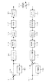
上述した符号化対象画素数の増加を防止した階層構造データに対し、上位階層データにクラス分類適応予測を適用することで、下位階層データを予測し、下位階層データとその予測値との差分(すなわち、残差信号)を生成することで伝送データ量の削減を図ることができる。図10は、そのような符号化ユニットを示す。入力端子41を介して第1階層データd0が入力画像データd0として平均化回路42および減算器46へ供給される。第1階層データが元の解像度の画像データである。
【0040】
入力画素データd0は、平均化回路42において、1/4平均処理が実行され、階層データd1が生成される。この階層データd1は、図9に示す第2階層データに対応する。生成された階層データd1は、平均化回路43および減算器47へ供給される。
【0041】
階層データd1に対して、平均化回路43では、平均化回路42と同様な処理が施され、階層データd2が生成される。この階層データd2は、第3階層データに対応する。生成された階層データd2は、平均化回路44および減算器48へ供給される。また、平均化回路44でも同様に階層データd2に対して1/4平均処理がなされ、階層データd3が生成される。この階層データd3は、第4階層データに対応する。生成された階層データd3は、平均化回路45および減算器49へ供給される。さらに、平均化回路45でも同様に階層データd3に対して1/4平均処理がなされ、階層データd4が生成される。この階層データd4は、第5階層データに対応する。生成された階層データd4は、量子化器54へ供給される。
【0042】
そして、これら5つの階層データについて階層間で予測が行われる。先ず、第5階層においてなされる圧縮のための量子化処理は、量子化器54によりなされる。この量子化器54の出力データd21が可変長符号のエンコーダ71に供給されると共に、逆量子化器58へも供給される。エンコーダ71の出力が出力端子76に第5階層のデータとして取り出される。符号化データd21が供給された逆量子化器58の出力データd16がクラス分類適応予測回路62へ供給される。
【0043】
クラス分類適応予測回路62では、データd16を使用して予測処理がなされ、第4階層データの予測値d12が生成され、この予測値d12が減算器49へ供給される。この減算器49では、平均化回路44から供給される階層データd3と予測値d12との差分値が求められ、その差分値d8が量子化器53へ供給される。
【0044】
差分値d8が供給された量子化器53では、量子化器54と同様に量子化ビット数を低減するように、再量子化がなされる。この量子化器53の出力データが演算器66および逆量子化器57へ供給される。この演算器66では、4画素から1画素を間引く処理が行われる。演算器66から出力されるデータd20が可変長符号のエンコーダ70で符号化され、エンコーダ70の出力が出力端子75に第4階層の出力データとして取り出される。
【0045】
クラス分類適応予測回路62により予測された第4階層データd12と、逆量子化器57の出力データ(復号残差信号)d15がクラス分類適応予測回路61へ供給される。クラス分類適応予測回路61では、データd12に対してデータd15を加算することによって、第4階層のローカル復号データを形成し、このローカル復号データを使用して予測処理がなされ、第3階層データの予測値d11が生成され、予測値d11が減算器48へ供給される。この減算器48では、平均化回路43から供給されるデータd2と予測値d11との差分値が求められ、その差分値d7が量子化器52へ供給される。
【0046】
差分値d7が供給された量子化器52の出力データが演算器65および逆量子化器56へ供給される。この演算器65では、4画素から1画素を間引く処理が行われる。演算器65から出力される第3階層データd19が可変長符号のエンコーダ69に供給され、エンコーダ69の出力が出力端子74に第3階層のデータとして取り出される。
【0047】
クラス分類適応予測回路61により予測された第3階層データd11と、量子化器52から符号化データが供給された逆量子化器56の出力データd14がクラス分類適応予測回路60へ供給される。クラス分類適応予測回路60では、データd11に対してデータd14を加算することによって、第3階層のローカル復号データを形成し、このローカル復号データを使用して予測処理がなされ、第2階層データの予測値d10が生成され、予測値d10が減算器47へ供給される。この減算器47では、平均化回路42から供給されるデータd1と予測値d10との差分値が求められ、その差分値d6が量子化器51へ供給される。
【0048】
量子化器51の出力データは、演算器64および逆量子化器55へ供給される。この演算器64では、4画素から1画素を間引く処理が行われる。演算器64から出力される第2階層データd18が可変長符号のエンコーダ68に供給され、エンコーダ68の出力が出力端子73に第2階層のデータとして取り出される。
【0049】
クラス分類適応予測回路60により予測された第2階層データd10と、量子化器51から符号化データが供給された逆量子化器55の出力データd13がクラス分類適応予測回路59へ供給される。クラス分類適応予測回路59では、データd10に対してデータd13を加算することによって、第2階層のローカル復号データを形成し、このローカル復号データを使用して予測処理がなされ、第1階層データの予測値d9が生成され、予測値d9が減算器46へ供給される。この減算器46では、入力端子41から供給される入力画素データd0と予測値d9との差分値が求められ、その差分値d5が量子化器50へ供給される。
【0050】
差分値d5が供給された量子化器50の出力データは、演算器63へ供給される。この演算器63では、4画素から1画素を間引く処理が行われる。演算器63から出力される第1階層データd17が可変長符号のエンコーダ67に供給され、エンコーダ67の出力が出力端子72に第1階層のデータとして取り出される。
【0051】
クラス分類適応予測回路59、60、61、62のそれぞれは、予測しようとする下位階層の画素をその空間的に近傍の複数の画素(上位階層に含まれる)のレベル分布に基づいて予測するものである。図12は、クラス分類適応予測回路の一例を示す。入力端子141からのローカル復号データが周辺コード値形成部142に供給される。周辺コード値形成部142は、予測しようとする下位階層の画素の近傍に位置する複数のデータx1 、x2 、・・・・、xn を同時化する。周辺コード値がクラス分類部143および遅延部145に供給される。クラス分類部143は、周辺コード値x1 〜xn のレベル分布のパターンと対応したクラスコードを出力する。クラスコードとしては、周辺コード値それ自体を使用しても良いが、クラス数が膨大となるので、周辺コードのそれぞれのビット数をADRC等により例えば1ビットに圧縮したものが使用される。クラス分類部143から発生したクラスコードが予測係数メモリ144に対してアドレス信号として供給される。
【0052】
予測係数メモリ144には、予め学習により獲得された予測係数w1 〜wn がアドレス毎に格納されている。すなわち、教師信号(例えば第4階層のデータ)と、入力信号(第4階層のデータから平均化処理で形成された第5階層のデータ)とを使用し、入力信号の複数のデータと係数との線形1次結合により予測値を求め、この予測値と教師信号の真値との誤差の自乗和を最小とするような係数がクラス毎に最小自乗法により求められる。クラスコードに対応して予測係数メモリ144から読出された予測係数w1〜wn と遅延部145からの周辺コード値x1 〜xn とが予測演算部146に供給される。
【0053】
予測演算部146では、下記の線形1次結合式によって、予測値yが計算される。
y=w1 x1 +w2 x2 +・・・・・+wn xn
予測演算部146により求められた予測値yが出力端子147に取り出される。なお、クラス分類のために使用される周辺コード値と、予測演算のために使用される周辺コード値とが異なったものでも良い。
【0054】
上述した一実施例における符号化ユニット125(図2参照)と同様の構成が階層符号化のエンコーダ側にも設けられている。つまり、符号化ユニット125と同様に、残差信号の存在範囲に適応して量子化特性を制御するようにした構成を量子化器50、51、52、53、54がそれぞれ有する。
【0055】
次に、上述のエンコーダと対応する階層符号化のデコーダ側の構成例を図11に示す。エンコーダ側で生成された各階層データは、d30〜d34として入力端子81、82、83、84、85にそれぞれ供給される。そして、可変長符号のデコーダ86、87、88、89、90にて可変長符号の復号がなされる。これらのデコーダに対して、逆量子化器91、92、93、94、95がそれぞれ接続される。
【0056】
先ず、第5階層入力データd34は、逆量子化器95において、エンコーダで施された量子化に対応する復号処理が行われ、画像データd39となり、クラス分類適応予測回路107および演算器103へ供給される。また画像データd39は、第5階層の画像出力として、出力端子112から取り出される。
【0057】
クラス分類適応予測回路107では、第4階層の画像データに対してクラス分類適応予測が施され、第4階層データの予測値d47が生成される。逆量子化器94からのデータd38(すなわち、差分値)と予測値d47とが加算器99で加算される。加算器99から画像データd43が演算器103へ供給され、演算器103では、非伝送画素の値を求めるために、上述した演算が実行され、逆量子化器95から供給された画像データd39と画像データd43から第4階層の全画素値が復元される。この演算器103において、復元された全画素値は、画像データd51として、クラス分類適応予測回路106および演算器102へ供給される。また画像データd51は、第4階層の出力として、出力端子111から取り出される。
【0058】
クラス分類適応予測回路106では、第3階層の画像データに対してクラス分類適応予測が施され、第3階層データの予測値d46が生成される。逆量子化器93からのデータd37と予測値d46とが加算器98で加算される。加算器98から画像データd42が演算器102へ供給され、演算器102により非伝送画素の値が求められ、演算器103から供給された画像データd51と画像データd42から第3階層の全画素値が復元される。この演算器102において、復元された全画素値は、画像データd50として、クラス分類適応予測回路105および演算器101へ供給される。また画像データd50は、第3階層の出力として、出力端子110から取り出される。
【0059】
また、クラス分類適応予測回路105では、第2階層の画像データに対してクラス分類適応予測が施され、第2階層データの予測値d45が生成される。逆量子化器92からのデータd36と予測値d45とが加算器97で加算される。加算器97から画像データd41が演算器101へ供給され、演算器101により非伝送画素の値が求められ、演算器102から供給された画像データd50と画像データd41から第2階層の全画素値が復元される。この演算器101において、復元された全画素値は、画像データd49として、クラス分類適応予測回路104および演算器100へ供給される。また画像データd49は、第2階層の出力として、出力端子109から取り出される。
【0060】
さらに、クラス分類適応予測回路104では、第1階層の画像データに対してクラス分類適応予測が施され、第1階層データの予測値d44が生成される。逆量子化器91からのデータd35と予測値d44とが加算器96で加算される。加算器96から画像データd40が演算器100へ供給され、演算器100により非伝送画素の値が求められ、演算器101から供給された画像データd49と画像データd40から第1階層の全画素値が復元される。この演算器100において、復元された全画素値は、画像データd48として、第1階層の出力として、出力端子108から取り出される。こうして、符号化対象画素数の増加を防止した階層符号化において、クラス分類適応予測を導入することで符号化効率の向上を図ることが可能となる。
【0061】
上述した一実施例の復号化ユニット134と同様の構成を逆量子化器91、92、93、94、95がそれぞれ有する。従って、上述した階層符号化に対してこの発明を適用した他の実施例によっても、上述した一実施例と同様に、ブロック化された残差信号を量子化歪みの増加を抑えつつ量子化することができる。
【0062】
この発明は、上述した予測符号化以外の予測符号化で発生した残差信号の量子化に対しても適用できる。また、この発明は、残差信号に限らず画像信号の量子化に対しても適用できる。さらに、この発明は、量子化ステップ幅を制御することによって、発生データ量を制御するバッファリングの構成を有するシステムに対しても適用することができる。
【0063】
【発明の効果】
この発明に依れば、ブロック化により存在範囲が狭いものとされたデータを量子化する場合、存在範囲に適応した量子化特性を選択するので、量子化歪みを少なくすることができる。
【図面の簡単な説明】
【図1】この発明を適用できる記録/再生、あるいは伝送システムの一例のブロック図である。
【図2】この発明の一実施例のブロック図である。
【図3】この発明の一実施例中の残差信号の生成と、そのブロック化の説明に用いる略線図である。
【図4】この発明の一実施例中の残差信号の説明に用いる略線図である。
【図5】この発明の一実施例中の量子化特性の説明に用いる略線図である。
【図6】量子化特性の他の例の説明に用いる略線図である。
【図7】この発明の一実施例における復号化ユニットのブロック図である。
【図8】階層符号化の一例の説明に用いる略線図である。
【図9】階層符号化の一例の説明に用いる略線図である。
【図10】階層符号化に対してこの発明を適用した他の実施例のエンコード側の構成の一例を示すブロック図である。
【図11】この発明の他の実施例のデコード側の構成の一例を示すブロック図である。
【図12】この発明の他の実施例中のクラス分類適応予測回路の一例を示すブロック図である。
【符号の説明】
2・・・最大値検出回路,3・・・最小値検出回路,6・・・分配器、7・・・セレクト信号生成回路、81 〜8n ・・・量子化器[0001]
BACKGROUND OF THE INVENTION
The present invention relates to an information signal encoding apparatus, encoding method, and decoding method that reduce the amount of generated data of digital information signals such as digital audio signals and digital image signals.
[0002]
[Prior art]
Predictive coding is known to reduce the amount of transmission information such as digital audio signals and digital image signals. For example, the one-dimensional DPCM forms a difference (residual) between the input sample value and the predicted value in the time direction, and the two-dimensional DPCM forms a residual between the input sample value and the predicted value in the spatial direction. Since the digital information signal has a correlation in the time direction and the spatial direction, the residual is concentrated in the vicinity of zero. Therefore, the residual signal can be quantized with a smaller number of bits than the original number of quantization bits, thereby reducing the amount of information. Further, the amount of information can be further compressed by performing variable length coding using the concentration of the distribution of residual signals. As the variable length coding, run length and Huffman coding are known.
[0003]
Furthermore, in order to reduce the quantization error, the quantization step of the value near 0 of the residual signal is made fine, and when the residual signal level is large, nonlinear quantization is also known, which makes the quantization step coarse. It has been.
[0004]
[Problems to be solved by the invention]
As one method for quantizing the residual signal, it has been proposed to collect the residual signal for each block, narrow the range in which the residual signal level exists, and reduce the number of quantization bits. . As described above, in the case of a residual signal that has been blocked, the level of the residual signal is not necessarily concentrated to 0 depending on the block, but has various level distributions. Accordingly, when the entire level range in which the blocked residual signal can exist is quantized by linear quantization, there is a problem that the quantization error increases when the number of quantization bits is reduced.
[0005]
Therefore, an object of the present invention is to provide an information signal encoding apparatus, an encoding method, and an encoding method capable of reducing the quantization error by selecting a quantization characteristic adapted to the distribution of the level of the blocked signal. And providing a decoding method.
[0006]
[Means for Solving the Problems]
The invention according to
Means for blocking the input digital information signal;
Detecting means for detecting a minimum value and a dynamic range for each block of the blocked input digital information signal;
Means for detecting the presence range of the level of the blocked input digital information signal based on the minimum value and the dynamic range, and generating a selection signal corresponding to the detected presence range;
Quantization value assignment is denser in a given quantization range than in other quantization ranges, and the given quantization range is differentAmong a plurality of quantization characteristics, including the existence range, andAbove givenQuantization means for selecting a quantization characteristic having the smallest difference between the quantization range and the existence range by the selection signal, and quantizing the input digital information signal blocked by the selected quantization characteristic;
Means for transmitting the output of the quantizing means and the selection signal;
An information signal encoding device characterized by comprising:
The invention according to
[0007]
The invention according to
Blocking the input digital information signal;
Detecting a block-by-block minimum value and dynamic range of the blocked input digital information signal;
Detecting a presence range of the level of the blocked input digital information signal based on the minimum value and the dynamic range, and generating a selection signal corresponding to the detected presence range;
Quantization value assignment is denser in a given quantization range than in other quantization ranges, and the given quantization range is differentAmong a plurality of quantization characteristics, including the existence range, andAbove givenA quantization characteristic having the smallest difference between the quantization range and the existence range is selected by the selection signal, and the input digital information signal blocked by the selected quantization characteristic is quantized;
Transmitting the output generated by the quantization and the selection signal;
An information signal encoding method characterized by comprising:
A fourth aspect of the present invention is an information signal encoding method in which the above-described quantization is applied to a block residual signal.
[0008]
According to a fifth aspect of the present invention, there is provided an information signal encoding apparatus in which at least first and second hierarchical data are formed from an input digital information signal, and the first and second hierarchical data are encoded and transmitted. ,
Means for forming second hierarchical data having a lower resolution than the first hierarchical data;
Means for predicting the first hierarchical data from the second hierarchical data;
Means for forming a residual signal between the predicted data and the first tier data;
Means for blocking the residual signal;
Detecting means for detecting a minimum value and a dynamic range for each block of the residual signal that has been blocked;
Means for detecting an existing range of the level of the blocked residual signal based on the minimum value and the dynamic range and generating a selection signal corresponding to the detected existing range;
Quantization value assignment is denser in a given quantization range than in other quantization ranges, and the given quantization range is differentAmong a plurality of quantization characteristics, including the existence range, andAbove givenQuantization means for quantizing the residual signal blocked by the selected quantization characteristic, the quantization characteristic having the smallest difference between the quantization range and the existence range is selected, and
Means for transmitting the output of the quantizing means and the selection signal;
An information signal encoding device characterized by comprising:
[0009]
According to a sixth aspect of the present invention, there is provided an information signal encoding method in which at least first and second layer data are formed from an input digital information signal, and the first and second layer data are encoded and transmitted. ,
Forming second hierarchical data having a lower resolution than the first hierarchical data;
Predicting first hierarchical data from second hierarchical data;
Forming a residual signal between the predicted data and the first tier data;
Blocking the residual signal;
Detecting a block-by-block minimum value and dynamic range of the blocked residual signal;
Detecting a presence range of the level of the blocked residual signal based on the minimum value and the dynamic range, and generating a selection signal corresponding to the detected presence range;
Quantization value assignment is denser in a given quantization range than in other quantization ranges, and the given quantization range is differentAmong a plurality of quantization characteristics, including the existence range, andAbove givenA quantization characteristic having the smallest difference between the quantization range and the existence range is selected by the selection signal, and the residual signal blocked by the selected quantization characteristic is quantized;
Transmitting the output generated by the quantization and the selection signal;
An information signal encoding method characterized by comprising:
[0010]
The invention according to
Receiving a selection signal and selecting an inverse quantization characteristic;
An inverse quantization step for converting the quantized output into a representative value according to the selected inverse quantization characteristic;
An information signal decoding method comprising the steps of: decomposing a residual signal converted into a representative value into blocks and converting the residual signal into an original order.
[0011]
The residual signal between the input digital information signal and the prediction signal is blocked. The minimum value and dynamic range of the residual signal in the block is detected. Based on the minimum value and the dynamic range, the distribution residual distribution of the block is examined. A quantization characteristic adapted to this level distribution bias is selected. Therefore, it is possible to reduce the quantization error. A quantization output and a selection signal for selecting a quantization characteristic are transmitted.
[0012]
DETAILED DESCRIPTION OF THE INVENTION
Hereinafter, an embodiment of the present invention will be described with reference to the drawings. In this embodiment, the present invention is applied to a digital image signal obtained by sampling a video signal at a predetermined sampling frequency and converting each sample into a predetermined number of quantization bits. FIG. 1 shows the overall configuration of a system according to an embodiment of the present invention.
[0013]
In FIG. 1, a digital video signal is supplied to an input terminal indicated by 121. The input signal is supplied to the
[0014]
As will be described later, the
[0015]
Data is reproduced from the
[0016]
The output of the
[0017]
The decoded residual signal is supplied to the
[0018]
FIG. 2 shows an example of the
[0019]
The
[0020]
The residual signal can be increased in concentration by blocking. When one pixel is 8-bit data, the distribution of the occurrence frequency of the residual signal of one screen is in the range of (−255 to +255) around 0, and the frequency of the residual is 0. Maximum. However, when divided into blocks, the residual level distribution has a narrower range than the original distribution. In the case of dividing into blocks, the maximum frequency of the residual does not necessarily match 0.
[0021]
This is due to the fact that the residuals in the blocks in the small space are relatively large in comparison with one screen, and the residuals are strongly correlated in the blocks. Further, the fact that the frequency of the value of 0 does not become maximum occurs when the luminance level gradually changes in the diagonal direction in the block, for example. The method of increasing the degree of concentration of the residual level distribution is an example of blocking, and other methods are also possible.
[0022]
Returning to FIG. 2, the
[0023]
In the
[0024]
A plurality of
[0025]
As described above, the residual signal generated by the predictive coding has various biases depending on the block, as shown in FIG. 4A. In FIG. 4A, the residual signal indicated by a is biased to the negative side, the residual signal indicated by b matches the value with the maximum frequency of 0, and the residual signal indicated by c is positive. It is biased to. An example of the residual signal of the block shown in FIG. 4B is (MIN = 0, MAX = + 255, DR = 255). That is, it is a residual signal having a level distribution biased to the positive side. An example of the residual signal of the block shown in FIG. 4C is (MIN = −255, MAX = 0, DR = 255). That is, it is a residual signal having a level distribution biased to the negative side.
[0026]
In general, if the code has n bits, 2nOr 2nThe range between MAX and MIN is divided into a range of −1. At the time of quantization, the same code is assigned to the residual signal belonging to the divided range. When the code is restored, it is converted to a representative value in the middle of the range. FIG. 5A shows the characteristics of conventional linear quantization. Here, n = 3, and the range between MAX and MIN is divided into seven ranges. On the vertical axis (output level), x indicates a representative value restored by inverse quantization. The conventional linear quantization is such that the quantization distortion is uniform for the seven level ranges.
[0027]
However, in the case of the residual signal shown in FIG. 4B, since the residual signal actually exists in the positive range, three quantized values are assigned to the positive and negative sides, respectively. In the case of linear quantization, assignment of the quantization value to the negative side is useless. Further, in the case of the residual signal shown in FIG. 4C, the allocation of the quantized value to the positive side is wasted. Therefore, in one embodiment of the present invention, non-linear quantization can be performed in consideration of the deviation of the distribution of the residual signal. For example, when the existence range of the residual signal is biased to the positive side, as shown in FIG. 5B, a nonlinear quantum such that five quantized values are assigned to the positive side and one quantized value is assigned to the negative side. To do. On the contrary, when the residual signal existence range is biased toward the negative side, nonlinear quantization is performed so that more quantization values are assigned to the negative side.
[0028]
A plurality of
[0029]
FIG. 6 shows another example of the quantization characteristic selected based on the dynamic range DR and the minimum value MIN. The vertical axis in FIG. 6 indicates the dynamic range DR (0 to +511), and the horizontal axis indicates the minimum value MIN (−255 to +255). The residual signal may exist below the diagonal line connecting DR = + 511 and MIN = + 255. In FIG. 6, by drawing a line that bisects the dynamic range DR and a line that equally divides the minimum value MIN into four, the residual signal that may exist is converted into six quantization characteristics Q1 to Q6 and the conventional one not shown. Can be quantized by the linear quantization characteristic of
[0030]
The quantization characteristic Q1 quantizes a residual signal having a distribution biased to the positive side. The quantization characteristic Q2 quantizes the residual signal having a distribution slightly biased to the positive side. The quantization characteristics Q3 and Q4 quantize the residual signal having a distribution slightly biased to the negative side. The quantization characteristics Q5 and Q6 quantize the residual signal having a distribution biased to 0 and negative. Also, in these quantization characteristics Q1 to Q6, it is not necessary to share the number of quantization bits, and the quantization characteristics Q1, Q2, QThree, QFiveThe number of quantization bits of n1And other quantization characteristics QFour, Q6The number of bits in n2You may make it differ. In this case, for example, n2> N1It is said. In the case where the residual signal exists over a plurality of ranges, linear quantization processing similar to the conventional one is performed.
[0031]
If a plurality of different quantization characteristics can be set so as to cover the existence range of the residual signal, quantization characteristics other than those shown in FIG. 6 may be set. For example, a characteristic for quantizing a range including 0 of the residual signal may be provided separately.
[0032]
An example of the
[0033]
[0034]
Next, another embodiment in which the present invention is applied to hierarchical coding will be described. The hierarchical encoding device described here can prevent an increase in the number of encoding target pixels by performing prediction between hierarchies and using a simple arithmetic expression for the inter-layer data.
[0035]
The hierarchical encoding method will be described with reference to FIG. FIG. 8 shows, as an example, a schematic diagram between four hierarchies having the first hierarchy as the lowest hierarchy (original picture) and the fourth hierarchy as the highest hierarchy. For example, when the average value of the lower layer data of four pixels corresponding spatially is adopted as the upper layer data generation method, the number of transmission pixels can be prevented from increasing.
[0036]
That is, the upper layer data is M and the lower layer pixel value is x.0 , X1 , X2 , XThree Then,
M = 1/4 · (x0 + X1 + X2 + XThree)
As a result, data M is formed. And, for example, x of the data M and the four dataThreeThe other three data are transmitted. On the receiving or playback side,
xThree = 4 · M- (x0 + X1 + X2 )
Non-transmission pixel x by a simple arithmetic expressionThree Can be easily restored. In FIG. 8, hatched rectangles indicate non-transmission pixels.
[0037]
FIG. 9 shows a configuration of hierarchical encoding of, for example, five layers using the above-described averaging. Assume that the first hierarchy is the resolution level of the input image. The block size of this first layer is (1 × 1). The second layer data is generated by averaging four pixels of the first layer data. In this example, the first hierarchy data X1 (0) to X1 Based on the average value of (3), the second hierarchical data X2 (0) is generated. X2 Second layer data X adjacent to (0)2 (1) to X2 Similarly, (3) is generated by averaging four pixels of the first layer data. The block size of the second hierarchy is (1/2 × 1/2).
[0038]
Further, the third layer data is generated by averaging four pixels of the second layer data corresponding spatially. The block size of the third hierarchy is (1/4 × 1/4). Similarly, the fourth layer data is generated from the third layer data. The block size of the fourth layer is (1/8 × 1/8). Finally, the fifth hierarchy data X which is the highest hierarchyFive (0) is the fourth layer data XFour (0) to XFour It is generated by the average value of (3). The block size of the fifth layer is (1/16 × 1/16).
[0039]
By applying the class classification adaptive prediction to the upper layer data for the hierarchical structure data in which the increase in the number of encoding target pixels is prevented, the lower layer data is predicted, and the difference between the lower layer data and the predicted value ( That is, it is possible to reduce the amount of transmission data by generating a residual signal. FIG. 10 shows such a coding unit. The first hierarchy data d0 is supplied as input image data d0 to the averaging circuit 42 and the subtractor 46 via the
[0040]
The input pixel data d0 is subjected to ¼ averaging processing in the averaging circuit 42 to generate hierarchical data d1. This hierarchical data d1 corresponds to the second hierarchical data shown in FIG. The generated hierarchical data d1 is supplied to the averaging circuit 43 and the subtractor 47.
[0041]
The averaging circuit 43 performs the same processing as the averaging circuit 42 on the hierarchical data d1, and generates hierarchical data d2. This hierarchical data d2 corresponds to the third hierarchical data. The generated hierarchical data d2 is supplied to the averaging circuit 44 and the
[0042]
And about these five hierarchical data, prediction is performed between hierarchies. First, the quantization processing for compression performed in the fifth layer is performed by the quantizer 54. The output data d21 of the quantizer 54 is supplied to the variable
[0043]
In the class classification adaptive prediction circuit 62, prediction processing is performed using the data d16, a predicted value d12 of the fourth layer data is generated, and the predicted value d12 is supplied to the
[0044]
In the
[0045]
The fourth layer data d12 predicted by the class classification adaptive prediction circuit 62 and the output data (decoded residual signal) d15 of the
[0046]
The output data of the
[0047]
The third layer data d11 predicted by the class classification adaptive prediction circuit 61 and the output data d14 of the
[0048]
The output data of the quantizer 51 is supplied to the arithmetic unit 64 and the
[0049]
The second hierarchy data d10 predicted by the class classification adaptive prediction circuit 60 and the output data d13 of the
[0050]
The output data of the
[0051]
Each of the class classification adaptive prediction circuits 59, 60, 61, and 62 predicts a lower layer pixel to be predicted based on a level distribution of a plurality of spatially neighboring pixels (included in the upper layer). It is. FIG. 12 shows an example of a class classification adaptive prediction circuit. Local decoded data from the input terminal 141 is supplied to the peripheral code value forming unit 142. The peripheral code value forming unit 142 includes a plurality of pieces of data x located in the vicinity of the lower layer pixel to be predicted.1, X2, ..., xnAre synchronized. The peripheral code value is supplied to the
[0052]
The prediction coefficient memory 144 stores the prediction coefficient w acquired in advance by learning.1~ WnIs stored for each address. That is, using a teacher signal (for example, fourth layer data) and an input signal (fifth layer data formed by averaging from the fourth layer data), a plurality of input signal data and coefficients A predicted value is obtained by linear linear combination of the above, and a coefficient that minimizes the square sum of errors between the predicted value and the true value of the teacher signal is obtained for each class by the method of least squares. Prediction coefficients w1 to w read from the prediction coefficient memory 144 corresponding to the class code.nAnd the peripheral code value x from the delay unit 1451~ XnAre supplied to the prediction calculation unit 146.
[0053]
In the prediction calculation unit 146, the predicted value y is calculated by the following linear linear combination formula.
y = w1x1+ W2x2+ ... + wnxn
The predicted value y obtained by the prediction calculation unit 146 is taken out to the
[0054]
A configuration similar to that of the encoding unit 125 (see FIG. 2) in the above-described embodiment is also provided on the encoder side of the hierarchical encoding. That is, like the
[0055]
Next, FIG. 11 shows a configuration example on the decoder side of the hierarchical encoding corresponding to the encoder described above. Each hierarchical data generated on the encoder side is supplied to input
[0056]
First, the fifth hierarchy input data d34 is subjected to decoding processing corresponding to the quantization performed by the encoder in the
[0057]
In the class classification adaptive prediction circuit 107, class classification adaptive prediction is performed on the image data of the fourth layer, and the predicted value d47 of the fourth layer data is generated. The
[0058]
In the class classification adaptive prediction circuit 106, class classification adaptive prediction is performed on the image data of the third hierarchy, and the predicted value d46 of the third hierarchy data is generated. The
[0059]
Also, the class classification adaptive prediction circuit 105 performs class classification adaptive prediction on the second layer image data, and generates a predicted value d45 of the second layer data. The
[0060]
Further, the class classification adaptive prediction circuit 104 performs class classification adaptive prediction on the first layer image data, and generates a predicted value d44 of the first layer data. The
[0061]
The
[0062]
The present invention can also be applied to quantization of a residual signal generated by predictive encoding other than the predictive encoding described above. The present invention can be applied not only to residual signals but also to quantization of image signals. Furthermore, the present invention can also be applied to a system having a buffering configuration for controlling the amount of generated data by controlling the quantization step width.
[0063]
【The invention's effect】
According to the present invention, when data whose existence range is narrowed by blocking is quantized, the quantization characteristic adapted to the existence range is selected, so that the quantization distortion can be reduced.
[Brief description of the drawings]
FIG. 1 is a block diagram of an example of a recording / reproducing or transmission system to which the present invention can be applied.
FIG. 2 is a block diagram of an embodiment of the present invention.
FIG. 3 is a schematic diagram used for explaining generation of a residual signal and its blocking in one embodiment of the present invention.
FIG. 4 is a schematic diagram used to describe a residual signal in one embodiment of the present invention.
FIG. 5 is a schematic diagram used for explaining quantization characteristics in one embodiment of the present invention;
FIG. 6 is a schematic diagram used for explaining another example of quantization characteristics;
FIG. 7 is a block diagram of a decoding unit in one embodiment of the present invention.
FIG. 8 is a schematic diagram used to describe an example of hierarchical encoding.
FIG. 9 is a schematic diagram used to describe an example of hierarchical encoding.
FIG. 10 is a block diagram showing an example of a configuration on the encoding side of another embodiment in which the present invention is applied to hierarchical encoding.
FIG. 11 is a block diagram showing an example of a configuration on the decoding side according to another embodiment of the present invention.
FIG. 12 is a block diagram showing an example of a class classification adaptive prediction circuit in another embodiment of the present invention.
[Explanation of symbols]
2 ... maximum value detection circuit, 3 ... minimum value detection circuit, 6 ... distributor, 7 ... select signal generation circuit, 81~ 8n... Quantizer
Claims (7)
上記入力ディジタル情報信号をブロック化する手段と、
上記ブロック化された入力ディジタル情報信号のブロック毎の最小値およびダイナミックレンジを検出する検出手段と、
上記最小値およびダイナミックレンジに基づいて、上記ブロック化された入力ディジタル情報信号のレベルの存在範囲を検出し、検出された上記存在範囲に対応する選択信号を発生する手段と、
量子化値の割り当てが所定の量子化範囲において他の量子化範囲における量子化値割り当てより密であり、上記所定の量子化範囲が異なる複数の量子化特性のうちで、上記存在範囲を含み、且つ、上記所定の量子化範囲と上記存在範囲との差が最も小さい量子化特性が上記選択信号によって選択され、選択された上記量子化特性で上記ブロック化された入力ディジタル情報信号を量子化する量子化手段と、
上記量子化手段の出力と上記選択信号とを伝送する手段と
からなることを特徴とする情報信号符号化装置。In an information signal encoding apparatus for encoding an input digital information signal so as to reduce the amount of generated data,
Means for blocking the input digital information signal;
Detecting means for detecting a minimum value and a dynamic range for each block of the input digital information signal that has been blocked;
Means for detecting an existing range of the level of the input digital information signal that has been blocked based on the minimum value and the dynamic range, and generating a selection signal corresponding to the detected existing range;
The quantization value assignment is denser than the quantization value assignment in the other quantization ranges in a predetermined quantization range, and includes the existence range among a plurality of quantization characteristics different in the predetermined quantization range , In addition, a quantization characteristic having the smallest difference between the predetermined quantization range and the existence range is selected by the selection signal, and the input digital information signal blocked by the selected quantization characteristic is quantized. Quantization means;
An information signal encoding apparatus comprising: means for transmitting the output of the quantization means and the selection signal.
上記入力ディジタル情報信号のサンプル値同士の残差信号を生成する手段と、
上記残差信号をブロック化する手段と、
上記ブロック化された残差信号のブロック毎の最小値およびダイナミックレンジを検出する検出手段と、
上記最小値およびダイナミックレンジに基づいて、上記ブロック化された残差信号のレベルの存在範囲を検出し、検出された上記存在範囲に対応する選択信号を発生する手段と、
量子化値の割り当てが所定の量子化範囲において他の量子化範囲における量子化値割り当てより密であり、上記所定の量子化範囲が異なる複数の量子化特性のうちで、上記存在範囲を含み、且つ、上記所定の量子化範囲と上記存在範囲との差が最も小さい量子化特性が上記選択信号によって選択され、選択された上記量子化特性で上記ブロック化された残差信号を量子化する量子化手段と、
上記量子化手段の出力と上記選択信号とを伝送する手段と
からなることを特徴とする情報信号符号化装置。In an information signal encoding apparatus for encoding an input digital information signal so as to reduce the amount of generated data,
Means for generating a residual signal between sample values of the input digital information signal;
Means for blocking the residual signal;
Detecting means for detecting a minimum value and a dynamic range for each block of the blocked residual signal;
Means for detecting a presence range of a level of the blocked residual signal based on the minimum value and the dynamic range, and generating a selection signal corresponding to the detected presence range;
The quantization value assignment is denser than the quantization value assignment in the other quantization ranges in a predetermined quantization range, and includes the existence range among a plurality of quantization characteristics different in the predetermined quantization range , In addition, a quantization characteristic having the smallest difference between the predetermined quantization range and the existence range is selected by the selection signal, and a quantizer that quantizes the block residual signal with the selected quantization characteristic. And
An information signal encoding apparatus comprising: means for transmitting the output of the quantization means and the selection signal.
上記入力ディジタル情報信号をブロック化するステップと、
上記ブロック化された入力ディジタル情報信号のブロック毎の最小値およびダイナミックレンジを検出するステップと、
上記最小値およびダイナミックレンジに基づいて、上記ブロック化された入力ディジタル情報信号のレベルの存在範囲を検出し、検出された上記存在範囲に対応する選択信号を発生するステップと、
量子化値の割り当てが所定の量子化範囲において他の量子化範囲における量子化値割り当てより密であり、上記所定の量子化範囲が異なる複数の量子化特性のうちで、上記存在範囲を含み、且つ、上記所定の量子化範囲と上記存在範囲との差が最も小さい量子化特性が上記選択信号によって選択され、選択された上記量子化特性で上記ブロック化された入力ディジタル情報信号を量子化するステップと、
上記量子化により発生した出力と上記選択信号とを伝送するステップと
からなることを特徴とする情報信号符号化方法。In an information signal encoding method for encoding an input digital information signal so as to reduce the amount of generated data,
Blocking the input digital information signal;
Detecting a minimum value and a dynamic range for each block of the blocked input digital information signal;
Detecting a presence range of the level of the blocked input digital information signal based on the minimum value and the dynamic range, and generating a selection signal corresponding to the detected presence range;
The quantization value assignment is denser than the quantization value assignment in the other quantization ranges in a predetermined quantization range, and includes the existence range among a plurality of quantization characteristics different in the predetermined quantization range , In addition, a quantization characteristic having the smallest difference between the predetermined quantization range and the existence range is selected by the selection signal, and the input digital information signal blocked by the selected quantization characteristic is quantized. Steps,
An information signal encoding method comprising: transmitting an output generated by the quantization and the selection signal.
上記入力ディジタル情報信号のサンプル値同士の残差信号を生成するステップと、
上記残差信号をブロック化するステップと、
上記ブロック化された残差信号のブロック毎の最小値およびダイナミックレンジを検出するステップと、
上記最小値およびダイナミックレンジに基づいて、上記ブロック化された残差信号のレベルの存在範囲を検出し、検出された上記存在範囲に対応する選択信号を発生するステップと、
量子化値の割り当てが所定の量子化範囲において他の量子化範囲における量子化値割り当てより密であり、上記所定の量子化範囲が異なる複数の量子化特性のうちで、上記存在範囲を含み、且つ、上記所定の量子化範囲と上記存在範囲との差が最も小さい量子化特性が上記選択信号によって選択され、選択された上記量子化特性で上記ブロック化された残差信号を量子化するステップと、
上記量子化により発生した出力と上記選択信号とを伝送するステップと
からなることを特徴とする情報信号符号化方法。In an information signal encoding method for encoding an input digital information signal so as to reduce the amount of generated data,
Generating a residual signal between sample values of the input digital information signal;
Blocking the residual signal;
Detecting a minimum value and a dynamic range for each block of the blocked residual signal;
Detecting an existing range of the level of the blocked residual signal based on the minimum value and the dynamic range, and generating a selection signal corresponding to the detected existing range;
The quantization value assignment is denser than the quantization value assignment in the other quantization ranges in a predetermined quantization range, and includes the existence range among a plurality of quantization characteristics different in the predetermined quantization range , And a quantization characteristic having the smallest difference between the predetermined quantization range and the existence range is selected by the selection signal, and the block residual signal is quantized by the selected quantization characteristic. When,
An information signal encoding method comprising: transmitting an output generated by the quantization and the selection signal.
上記第1の階層データより解像度がより低い上記第2の階層データを形成する手段と、
上記第2の階層データから上記第1の階層データを予測する手段と、
上記予測されたデータと上記第1の階層データとの残差信号を形成する手段と、
上記残差信号をブロック化する手段と、
上記ブロック化された残差信号のブロック毎の最小値およびダイナミックレンジを検出する検出手段と、
上記最小値およびダイナミックレンジに基づいて、上記ブロック化された残差信号のレベルの存在範囲を検出し、検出された上記存在範囲に対応する選択信号を発生する手段と、
量子化値の割り当てが所定の量子化範囲において他の量子化範囲における量子化値割り当てより密であり、上記所定の量子化範囲が異なる複数の量子化特性のうちで、上記存在範囲を含み、且つ、上記所定の量子化範囲と上記存在範囲との差が最も小さい量子化特性が上記選択信号によって選択され、選択された上記量子化特性で上記ブロック化された残差信号を量子化する量子化手段と、
上記量子化手段の出力と上記選択信号とを伝送する手段と
からなることを特徴とする情報信号符号化装置。In an information signal encoding apparatus, wherein at least first and second hierarchical data are formed from an input digital information signal, and the first and second hierarchical data are encoded and transmitted.
Means for forming the second hierarchical data having a lower resolution than the first hierarchical data;
Means for predicting the first hierarchical data from the second hierarchical data;
Means for forming a residual signal between the predicted data and the first hierarchical data;
Means for blocking the residual signal;
Detecting means for detecting a minimum value and a dynamic range for each block of the blocked residual signal;
Means for detecting a presence range of a level of the blocked residual signal based on the minimum value and the dynamic range, and generating a selection signal corresponding to the detected presence range;
The quantization value assignment is denser than the quantization value assignment in the other quantization ranges in a predetermined quantization range, and includes the existence range among a plurality of quantization characteristics different in the predetermined quantization range , In addition, a quantization characteristic having the smallest difference between the predetermined quantization range and the existence range is selected by the selection signal, and a quantizer that quantizes the block residual signal with the selected quantization characteristic. And
An information signal encoding apparatus comprising: means for transmitting the output of the quantization means and the selection signal.
上記第1の階層データより解像度がより低い上記第2の階層データを形成するステップと、
上記第2の階層データから上記第1の階層データを予測するステップと、
上記予測されたデータと上記第1の階層データとの残差信号を形成するステップと、
上記残差信号をブロック化するステップと、
上記ブロック化された残差信号のブロック毎の最小値およびダイナミックレンジを検出するステップと、
上記最小値およびダイナミックレンジに基づいて、上記ブロック化された残差信号のレベルの存在範囲を検出し、検出された上記存在範囲に対応する選択信号を発生するステップと、
量子化値の割り当てが所定の量子化範囲において他の量子化範囲における量子化値割り当てより密であり、上記所定の量子化範囲が異なる複数の量子化特性のうちで、上記存在範囲を含み、且つ、上記所定の量子化範囲と上記存在範囲との差が最も小さい量子化特性が上記選択信号によって選択され、選択された上記量子化特性で上記ブロック化された残差信号を量子化するステップと、
上記量子化により発生した出力と上記選択信号とを伝送するステップと
からなることを特徴とする情報信号符号化方法。In an information signal encoding method in which at least first and second layer data are formed from an input digital information signal, and the first and second layer data are encoded and transmitted,
Forming the second hierarchical data having a lower resolution than the first hierarchical data;
Predicting the first hierarchical data from the second hierarchical data;
Forming a residual signal between the predicted data and the first hierarchical data;
Blocking the residual signal;
Detecting a minimum value and a dynamic range for each block of the blocked residual signal;
Detecting an existing range of the level of the blocked residual signal based on the minimum value and the dynamic range, and generating a selection signal corresponding to the detected existing range;
The quantization value assignment is denser than the quantization value assignment in the other quantization ranges in a predetermined quantization range, and includes the existence range among a plurality of quantization characteristics different in the predetermined quantization range , And a quantization characteristic having the smallest difference between the predetermined quantization range and the existence range is selected by the selection signal, and the block residual signal is quantized by the selected quantization characteristic. When,
An information signal encoding method comprising: transmitting an output generated by the quantization and the selection signal.
上記選択信号を受け取って、逆量子化特性を選択するステップと、
上記選択された逆量子化特性によって量子化出力を代表値へ変換する逆量子化のステップと、
上記代表値に変換された残差信号をブロック分解し、元の順序へ変換するステップとからなることを特徴とする情報信号復号方法。 Quantization value assignment selected in response to a selection signal corresponding to the presence range of the residual signal level detected based on the minimum value of the block and the dynamic range, and other quantization ranges within a given quantization range Among the plurality of quantization characteristics that are denser than the quantized value allocation in FIG. 4 and have different predetermined quantization ranges, the difference between the predetermined quantization range and the existing range is the largest. In an information signal decoding method for an encoding method in which a blocked residual signal is quantized by a small quantization characteristic and a quantized output and the selection signal are transmitted,
Receiving the selection signal and selecting an inverse quantization characteristic;
An inverse quantization step of converting the quantized output into a representative value according to the selected inverse quantization characteristic;
A method of decoding an information signal, comprising: performing block decomposition on the residual signal converted into the representative value and converting the residual signal into an original order.
Priority Applications (1)
| Application Number | Priority Date | Filing Date | Title |
|---|---|---|---|
| JP19712496A JP3968799B2 (en) | 1995-07-21 | 1996-07-08 | Information signal encoding apparatus, encoding method, and information signal decoding method |
Applications Claiming Priority (3)
| Application Number | Priority Date | Filing Date | Title |
|---|---|---|---|
| JP20777695 | 1995-07-21 | ||
| JP7-207776 | 1995-07-21 | ||
| JP19712496A JP3968799B2 (en) | 1995-07-21 | 1996-07-08 | Information signal encoding apparatus, encoding method, and information signal decoding method |
Publications (2)
| Publication Number | Publication Date |
|---|---|
| JPH0998419A JPH0998419A (en) | 1997-04-08 |
| JP3968799B2 true JP3968799B2 (en) | 2007-08-29 |
Family
ID=26510185
Family Applications (1)
| Application Number | Title | Priority Date | Filing Date |
|---|---|---|---|
| JP19712496A Expired - Fee Related JP3968799B2 (en) | 1995-07-21 | 1996-07-08 | Information signal encoding apparatus, encoding method, and information signal decoding method |
Country Status (1)
| Country | Link |
|---|---|
| JP (1) | JP3968799B2 (en) |
Family Cites Families (8)
| Publication number | Priority date | Publication date | Assignee | Title |
|---|---|---|---|---|
| JPS63109681A (en) * | 1986-10-28 | 1988-05-14 | Konica Corp | Picture processor |
| JPS6412764A (en) * | 1987-07-07 | 1989-01-17 | Nec Corp | Encoding/decoding method and device for picture signal |
| JPH0313090A (en) * | 1989-06-09 | 1991-01-22 | Matsushita Electric Ind Co Ltd | High efficient coding method for video signal |
| JP2560873B2 (en) * | 1990-02-28 | 1996-12-04 | 日本ビクター株式会社 | Orthogonal transform coding Decoding method |
| JPH0654199A (en) * | 1992-07-31 | 1994-02-25 | Matsushita Electric Ind Co Ltd | Highly efficient encoding device of digital image data |
| JPH0787327A (en) * | 1993-09-17 | 1995-03-31 | Fuji Xerox Co Ltd | Image coding device |
| JPH0795420A (en) * | 1993-09-22 | 1995-04-07 | Seiko Epson Corp | Picture data compressing method |
| JP3590996B2 (en) * | 1993-09-30 | 2004-11-17 | ソニー株式会社 | Hierarchical encoding and decoding apparatus for digital image signal |
-
1996
- 1996-07-08 JP JP19712496A patent/JP3968799B2/en not_active Expired - Fee Related
Also Published As
| Publication number | Publication date |
|---|---|
| JPH0998419A (en) | 1997-04-08 |
Similar Documents
| Publication | Publication Date | Title |
|---|---|---|
| US8619860B2 (en) | System and method for scalable encoding and decoding of multimedia data using multiple layers | |
| CN1117482C (en) | Method for encoding video signal using feature point based motion estimation | |
| US6078694A (en) | Image signal padding method, image signal coding apparatus, image signal decoding apparatus | |
| US5966179A (en) | Information signal encoding apparatus, encoding method thereof, information signal decoding method, and information signal record medium thereof | |
| US20060098881A1 (en) | Method and apparatus for encoding and decoding image data | |
| KR20010110629A (en) | Method and system for compressing motion image information | |
| US5825313A (en) | Information signal encoding apparatus, encoding method thereof, information signal decoding method, and information signal record medium thereof | |
| JP2007521740A (en) | How to find zeros in the transformation domain early | |
| JPH06125543A (en) | Encoding device | |
| JP2005519543A (en) | Method and system for layer video coding | |
| KR100444931B1 (en) | Hierarchical Image Encoding Device and Hierarchical Image Encoding Method | |
| KR100423226B1 (en) | Quantization Device and Quantization Method | |
| JP3629826B2 (en) | Information signal encoding apparatus, encoding method, and information signal decoding method | |
| JP3968799B2 (en) | Information signal encoding apparatus, encoding method, and information signal decoding method | |
| JP2004511978A (en) | Motion vector compression | |
| JP3834880B2 (en) | Information signal encoding apparatus, encoding method, and information signal decoding method | |
| JP3496402B2 (en) | Information signal encoding apparatus, encoding method, and information signal decoding method | |
| JP3309639B2 (en) | Quantization device and quantization method | |
| JPH0388488A (en) | Picture coding system | |
| JP2000165873A (en) | Compression method for moving picture information and its system | |
| JP3341528B2 (en) | Quantization device and quantization method | |
| US20010043653A1 (en) | Method and apparatus for image encoding method and appartus for image decoding and recording medium | |
| JP4168299B2 (en) | Image data conversion apparatus and image data conversion method | |
| JP3509346B2 (en) | Encoding device and encoding method | |
| JP2924279B2 (en) | Image signal prediction encoding / decoding device |
Legal Events
| Date | Code | Title | Description |
|---|---|---|---|
| A977 | Report on retrieval |
Free format text: JAPANESE INTERMEDIATE CODE: A971007 Effective date: 20050805 |
|
| A131 | Notification of reasons for refusal |
Free format text: JAPANESE INTERMEDIATE CODE: A131 Effective date: 20050823 |
|
| A521 | Request for written amendment filed |
Free format text: JAPANESE INTERMEDIATE CODE: A523 Effective date: 20051021 |
|
| A02 | Decision of refusal |
Free format text: JAPANESE INTERMEDIATE CODE: A02 Effective date: 20060926 |
|
| A521 | Request for written amendment filed |
Free format text: JAPANESE INTERMEDIATE CODE: A523 Effective date: 20061121 |
|
| A911 | Transfer to examiner for re-examination before appeal (zenchi) |
Free format text: JAPANESE INTERMEDIATE CODE: A911 Effective date: 20061211 |
|
| TRDD | Decision of grant or rejection written | ||
| A01 | Written decision to grant a patent or to grant a registration (utility model) |
Free format text: JAPANESE INTERMEDIATE CODE: A01 Effective date: 20070515 |
|
| A61 | First payment of annual fees (during grant procedure) |
Free format text: JAPANESE INTERMEDIATE CODE: A61 Effective date: 20070528 |
|
| FPAY | Renewal fee payment (event date is renewal date of database) |
Free format text: PAYMENT UNTIL: 20100615 Year of fee payment: 3 |
|
| FPAY | Renewal fee payment (event date is renewal date of database) |
Free format text: PAYMENT UNTIL: 20100615 Year of fee payment: 3 |
|
| FPAY | Renewal fee payment (event date is renewal date of database) |
Free format text: PAYMENT UNTIL: 20110615 Year of fee payment: 4 |
|
| FPAY | Renewal fee payment (event date is renewal date of database) |
Free format text: PAYMENT UNTIL: 20120615 Year of fee payment: 5 |
|
| FPAY | Renewal fee payment (event date is renewal date of database) |
Free format text: PAYMENT UNTIL: 20130615 Year of fee payment: 6 |
|
| R250 | Receipt of annual fees |
Free format text: JAPANESE INTERMEDIATE CODE: R250 |
|
| R250 | Receipt of annual fees |
Free format text: JAPANESE INTERMEDIATE CODE: R250 |
|
| LAPS | Cancellation because of no payment of annual fees |