JP4168299B2 - Image data conversion apparatus and image data conversion method - Google Patents
Image data conversion apparatus and image data conversion method Download PDFInfo
- Publication number
- JP4168299B2 JP4168299B2 JP27328898A JP27328898A JP4168299B2 JP 4168299 B2 JP4168299 B2 JP 4168299B2 JP 27328898 A JP27328898 A JP 27328898A JP 27328898 A JP27328898 A JP 27328898A JP 4168299 B2 JP4168299 B2 JP 4168299B2
- Authority
- JP
- Japan
- Prior art keywords
- data
- image data
- class
- code
- tap
- Prior art date
- Legal status (The legal status is an assumption and is not a legal conclusion. Google has not performed a legal analysis and makes no representation as to the accuracy of the status listed.)
- Expired - Fee Related
Links
Images


Description
【0001】
【発明の属する技術分野】
本発明は画像データ変換装置及び画像データ変換方法に関し、例えば画像データの画質を改善する画像データ変換装置に適用して好適なものである。
【0002】
【従来の技術】
従来、画像データの圧縮符号化方式としてMPEG(Moving Picture Experts Group)2規格による符号化方式がある。このMPEG2規格による符号化方式を用いた送受信システムは、送信側で、画像データに対してMPEG2規格による圧縮符号化処理を施して送信し、受信側で、受信した画像データを伸長復号化することにより元の画像データを復元している。
【0003】
【発明が解決しようとする課題】
ところでこのような送受信システムの受信装置においては、伸長復号化された標準精細度の画像データをその各画素の信号レベル分布に応じたクラスに分類した後、予測係数と呼ばれるデータが予め格納されているメモリからそのクラスに対応する予測係数を読み出し、当該予測係数と伸長復号化された標準精細度の画像データとから高精細度の画像データを予測演算するいわゆるクラス分類適応処理を用いたアップコンバータが考えられている。
【0004】
一般に、MPEG2規格によって圧縮符号化された画像データは、Iピクチャ(Intra coded picture) と、Pピクチャ(Predictive coded picture)と、Bピクチャ(Bidirectionally predictive coded picture)とから形成されている。Iピクチャは、フレーム内符号化を施し、そのフレーム画像内の情報だけを符号化して生成されたものである。Pピクチャは、そのフレーム画像よりも過去のIピクチャ又はPピクチャから予測符号化して生成されたものである。Bピクチャは、そのフレーム画像よりも過去及び又は未来のPピクチャ又はIピクチャの双方から予測符号化して生成されたものである。
【0005】
このようにMPEG2規格による符号化方式を用いた送受信システムでは、フレーム毎に異なる圧縮符号化処理が行われていることから、圧縮符号化された画像データを伸長復号化しても、フレーム画像に対して施された符号化処理に応じてその再現率が異なり、フレーム毎に精細度の異なる画像データが生成されることになる。
【0006】
上述のアップコンバータでは、伸長復号化された画像データに対して全て同様のクラス分類適応処理を施しているが、フレーム毎に画像の再現率すなわち精細度が異なることから、予測演算された画像データに時間方向の歪みや表示画面上のちらつきいわゆるフリッカが生じてしまい、画質の改善を妨げる問題が生じることになる。
【0007】
本発明は以上の点を考慮してなされたもので、従来に比して一段と画質を向上し得る画像データ変換装置及び画像データ変換方法を提案しようとするものである。
【0008】
【課題を解決するための手段】
かかる課題を解決するため本発明においては、圧縮された標準画像データを伸長復号化することにより標準復号化画像データを生成する標準復号化画像データ生成手段と、標準復号化画像データのフレーム画像及び当該フレーム画像の周辺フレームにおけるピクチャタイプの変化を示すピクチャパターンデータを生成するピクチャパターンデータ生成手段と、ピクチャパターンデータから現フレーム画像及び当該現フレーム画像の前後数フレーム分に相当するパターン部分を抽出した結果のピクチャパターン列に応じた分類コードを生成する分類コード生成手段と、標準復号化画像データから注目画素及び当該注目画素を中心とした複数の周辺画素をクラスタップとして設定し、当該クラスタップの信号レベル分布を示すクラスタップデータを特徴量として抽出し、当該クラスタップデータに対して所定の圧縮処理を施すことにより圧縮クラスタップコードを生成する圧縮クラスタップコード生成手段と、分類コードと圧縮クラスタップコードとを合成することによりクラスコードを生成するクラスコード生成手段と、予め基準とされる基準高精細度画像データから所定の画像データを間引くことにより生成した基準標準画像データに対し所定の基準クラスタップの信号レベル分布に基づいた基準クラスコードを生成し、基準標準画像データよりも画素数の多い基準高精細度画像データを生成する場合の基準予測タップを算出するときに用いられる基準予測係数データを当該基準クラスコードに対応させて予め記憶する基準予測係数データ記憶手段と、基準予測係数データ記憶手段に予め記憶された基準クラスコードと基準予測係数データとの対応関係を示すテーブルを用いてクラスコードに対応した予測係数データを読み出す予測係数データ読出手段と、標準復号化画像データから注目画素及び注目画素を中心とした複数の周辺画素を予測演算用の予測タップとして選定し、当該予測タップの信号レベル分布を示す予測タップデータを抽出する予測タップデータ抽出手段と、予測タップデータと予測係数データとを用いて、所定の数式で表される積和演算処理を施すことにより標準画素数でなる標準画像データよりも高精細度画素数でなる高精細度画像データを生成するようにした。
【0009】
この結果、復号化画像データに対して、全フレーム全てクラス分類適応処理を施した場合に比べ、フレーム毎に変化するピクチャータイプに応じてクラス分類適応処理を施すため、画像の精細度に応じたクラス分類適応処理が行われ、予測演算された画像データにおける各フレーム間の時間方向の歪やフリッカのない第2の画像データを生成することができる。
【0010】
【発明の実施の形態】
以下図面について、本発明の一実施の形態を詳述する。
【0011】
(1)クラス分類適応処理の原理
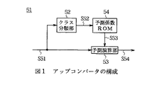
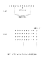
ここで図1は、クラス分類適応処理を実現するアップコンバータ51の回路構成を示す。アップコンバータ51は、外部から供給される例えば8ビットのパルス符号変調(PCM:Pulse Code Modulation )データでなるSD画像データS51をクラス分類部52及び予測演算部53に入力する。クラス分類部52は、例えば図2に示すように、SD画像データS51のうち注目画素及び当該注目画素を中心とした複数の周辺画素でなる合計7画素(タップ)をクラス分類用の画素(以下、これをクラスタップと呼ぶ)として設定し、それらの信号レベル分布に基づいてクラスコードS52を生成する。因みに、図中実線は第1フィールドを示し、点線は第2フィールドを示す。
【0012】
このクラス分類部52によってクラスコードS52を生成する方法としては、PCMデータを直接使用する(すなわちPCMデータをそのままクラスデータS52とする)方法や、ADRC(Adaptive Dynamic Range Coding )等のデータ圧縮方法を用いてクラス数を削減するような方法が考えられる。このうちPCMデータをそのままクラスコードS52とする方法では、クラスタップとして8ビットのPCMデータを7タップ用いることから、クラス数が256という膨大な数のクラス数に分類されることになり、実用上問題がある。
【0013】
そこで実際には、クラス分類部52は、ADRCのようなデータ圧縮処理(すなわち再量子化処理)を施すことによりクラス数を削減するようになされている。このADRCによる分類法は、注目画素を中心とする近傍領域内の数タップからADRCコードを、次式
【0014】
【数1】

によって求め、当該ADRCコードに基づいてクラスコードS52を生成する手法を用いている。ここで、ci はADRCコード、xi は各クラスタップの入力画素値、MINは領域内にある各クラスタップの入力画素値のうちの最小画素値、DRは領域内のダイナミックレンジ(最大画素値と最小画素値との差分)、kは再量子化ビット数である。
【0016】
すなわちADRCによる分類法は、領域内のダイナミックレンジから再量子化ビット数に応じた量子化ステップ幅を算出し、入力画素値から最小画素値を減算した画素値を量子化ステップ幅に応じて再量子化するものである。例えば領域内の7タップにおいて各クラスタップを1ビットに再量子化する1ビットADRCを行う場合では、領域内のダイナミックレンジに基づいて7タップの各入力画素値を適応的に1ビット量子化し、その結果、7タップの入力画素値を7ビットのデータに削減することができるので、全体としてクラス数を128クラスにまで削減することができる。
【0017】
図1に戻って、予測係数ROM(Read Only Memory)54は、後述する学習回路60によって予め生成された各クラス毎に対応する予測係数データS53を格納しており、クラス分類部52から供給されるクラスコードS52に応じた予測係数データS53を読み出し、これを予測演算部53に送出する。予測演算部53は、例えば図3に示すように、外部から入力されるSD画像データS51のうち、注目画素及び当該注目画素を中心とした複数の周辺画素でなる合計13タップを予測演算用の画素(以下、これを予測タップと呼ぶ)として選定し、当該予測タップの各画素値と予測係数データS53とを用いて、線形一次結合でなる次式
【0018】
【数2】
によって表される積和演算を行うことにより、予測タップには存在しないHD画素の集まりであるHD画像データS54を生成し、これを外部に出力する。ここで、x′は各HD画素値、xi は各予測タップの画素値、wi は予測係数、nは予測タップ数であり、この場合nは13である。
【0020】
ところで図4は、予測係数ROM54に格納されている予測係数データを生成する学習回路60の回路構成を示し、当該学習回路60は、予測係数データを予め生成して、これを予測係数ROM54に格納するようになされている。学習回路60は、いわゆる教師信号としてのHD画像データS60を垂直間引きフィルタ61及び予測係数算出回路62に入力する。学習回路60は、HD画像データS60を垂直間引きフィルタ61及び水平間引きフィルタ62によって間引くことにより、生徒信号としてのSD画像データS61を生成し、これをクラス分類部64及び予測係数算出回路62に入力するようになされている。
【0021】
クラス分類部64は、図1に示すアップコンバータのクラス分類部52と同様の構成でなり、SD画像データS61からクラスタップを選定し、その信号レベル分布に基づいてクラスコードS62を生成した後、これを予測係数算出回路62に送出する。予測係数算出回路62は、HD画像データS60及びSD画像データS61を基に、クラスコードS62が示すクラスに応じた予測係数をクラス毎に算出し、その結果得た予測係数データS63を予測係数ROM54に格納する。
【0022】
この場合、予測係数算出回路62は、上述の(2)式における予測係数wを最小自乗法によって求めるようになされている。具体的には予測係数算出回路62は、XをSD画素値、Wを予測係数、YをHD画素値として、いわゆる観測方程式と呼ばれる次式
【0023】
【数3】
を生成するように各データを収集する。ここでmは予測するHD画素の画素数を示す学習データ数、nは予測タップ数である。
【0025】
次に予測係数算出回路62は、この(3)式を基に、次式
【0026】
【数4】
に示す残差方程式を立てる。従って各予測係数wi は、この(4)式から、次式
【0028】
【数5】
が最小のときに最適な値となることがわかる。すなわち次式
【0030】
【数6】
を満たすように予測係数wi が算出される。
【0032】
そこで予測係数算出回路62は、このn個ある(6)式を満たすようなw1 、w2 、……、wn を算出すればよいことになり、上述の(4)式から、次式
【0033】
【数7】
を得、これら(6)及び(7)式から、次式
【0035】
【数8】
を求める。そして予測係数算出回路62は、上述の(4)及び(8)式から、次式
【0037】
【数9】
によって表される正規方程式を生成する。このようにして予測係数算出回路62は、予測タップ数nと同一次数の連立方程式でなる正規方程式を生成し、掃き出し法(Gauss Jordanの消去法)を用いてこの正規方程式を解くことにより、各予測係数wi を算出する。
【0039】
以下、学習回路60による予測係数生成手順について図5に示すフローチャートを用いて説明する。ステップSP61から入ったステップSP62において、学習回路60は、教師信号としてのHD画像データS60から生徒信号としてのSD画像データS61を生成することにより、予測係数を生成するのに必要な学習データを生成する。ステップSP63において、学習回路60は、予測係数を生成するのに必要十分な学習データが得られたか否か判定し、その結果、未だ必要十分な学習データが得られていないと判断された場合にはステップSP63において否定結果を得ることによりステップSP64に移行する。
【0040】
ステップSP64において、学習回路60は、SD画像データS61からクラスタップを選定し、その信号レベル分布に基づいてクラス分類を行う。ステップSP65において、学習回路60は、各クラス毎に上述の(9)式でなる正規方程式を生成し、ステップSP62に戻って同様の処理手順を繰り返すことにより、予測係数を生成するのに必要十分な正規方程式を生成する。
【0041】
これに対してステップSP63において肯定結果が得られると、このことは必要十分な学習データが得られたことを表しており、このとき学習回路60はステップSP66に移って、上述の(9)式でなる正規方程式を掃き出し法によって解くことにより、予測係数w1 、w2 、……、wn を各クラス毎に生成する。そしてステップSP67において、学習回路60は、生成した各クラス毎の予測係数w1 、w2 、……、wn を予測係数ROM54に格納し、ステップSP68に移って処理を終了する。
【0042】
(2)第1の実施の形態
図6において、100は全体として図1〜図5について上述したクラス分類適応処理の原理を用いた第1の実施の形態のアップコンバータの構成を示す。アップコンバータ100は、外部からMPEG2方式を用いて圧縮符号化された符号化画像データS100が供給されると、これをデコーダ101に入力する。デコード101は、この符号化画像データS100を伸長復号化することにより画像データS101を復元し、これを領域切り出し部102及び103に送出する。その際、デコーダ101は、フレーム毎に異なるデコード情報、例えば図7(A)に示すように、現在のフレームとその周辺のフレームにおけるピクチャタイプの変化情報を示すピクチャタイプパターンデータS102を生成し、これを範囲切り出し部104に送出する。
【0043】
範囲切り出し部104は、供給されたピクチャタイプパターンデータS102の中から参照範囲、例えば現在のフレームとその前後3フレームとを切り出し、この切り出されたピクチャタイプパターンデータS103を判定部105に送出する。判定部105は、図7(B)に示すように、この切り出されたピクチャタイプパターンデータS103をそのパターン列に応じた分類コードS104に変換し、これをクラスコード発生部106に送出する。
【0044】
ところで領域切り出し部102は、画像データS101からクラスタップを抽出し、それらの信号レベル分布を示すクラスタップデータS110を特徴量抽出部110に送出する。特徴量抽出部110は、クラスタップデータS110に対して1ビットADRCを施すことによりADRCコードS111を生成し、これをクラスコード発生部106に送出する。
【0045】
クラスコード発生部106は、上述の分類コードS104とADRCコードS111とを合成することによりクラスコードS112を生成し、これをROM111に送出する。ROM111は、後述する学習回路によって予め生成されたクラス毎に対応する予測係数を格納しており、クラスコード発生部106から供給されるクラスコードS112に応じた予測係数データS113を読み出し、これを予測演算部112に送出する。
【0046】
一方、領域切り出し部103は、画像データS101から予測タップを抽出し、それらの信号レベル分布を示す予測タップデータS114を予測演算部112に送出する。予測演算部112は、予測係数データS113と予測タップデータS114との積和演算を施すことにより高精細度の画像データS115を生成し、これを外部に出力する。
【0047】
続いて図8は、ROM111(図6)に格納されている予測係数を生成する学習回路120の構成を示す。学習回路120は、教師画像として高精細度の画像データS120をエンコーダ121及び正規方程式演算部122に送出する。エンコーダ121は、画像データS120をMPEG2方式を用いて圧縮符号化し、その結果得られる符号化画像データS121をデコーダ123に送出する。
【0048】
デコーダ123は、アップコンバータ100のデコーダ101(図6)と同様に構成されており、符号化画像データS121を伸長復号化することにより生徒画像としての標準精細度の画像データS122を生成し、これを領域切り出し部124及び125に送出する。その際、デコーダ123は、フレーム毎に異なるデコード情報、例えば現在のフレームとその周辺のフレームにおけるピクチャタイプの変化情報を示すピクチャタイプパターンデータS123を生成し、これを範囲切り出し部126に送出する。
【0049】
範囲切り出し部126は、アップコンバータ100の範囲切り出し部104(図6)と同様に構成されており、供給されたピクチャタイプパターンデータS123の中から参照範囲、例えば現在のフレームとその前後3フレームとを切り出し、この切り出されたピクチャタイプパターンデータS124を判定部127に送出する。判定部127は、アップコンバータ100の判定部105(図6)と同様に構成されており、この切り出されたピクチャタイプパターンデータS124をそのパターン列に応じた分類コードS125に変換し、これをクラスコード発生部128に送出する。
【0050】
ところで領域切り出し部124は、アップコンバータ100の領域切り出し部102(図6)と同様に構成されており、画像データS122からクラスタップを抽出し、それらの信号レベル分布を示すクラスタップデータS130を特徴量抽出部130に送出する。特徴量抽出部130は、アップコンバータ100の特徴量抽出部110(図6)と同様に構成されており、クラスタップデータS130に対して1ビットADRCを施すことによりADRCコードS131を生成し、これをクラスコード発生部128に送出する。
【0051】
クラスコード発生部128は、アップコンバータ100のクラスコード発生部106(図6)と同様に構成されており、上述の分類コードS125とADRCコードS131とを合成することによりクラスコードS132を生成し、これを正規方程式演算部122に送出する。
【0052】
一方、領域切り出し部125は、アップコンバータ100の領域切り出し部103(図6)と同様に構成されており、画像データS122から予測タップを抽出し、それらの信号レベル分布を示す予測タップデータS133を正規方程式演算部122に送出する。正規方程式演算部122は、高精細度の画像データS120と予測タップデータS133とから、クラスコードS132毎に正規方程式を生成し、この正規方程式データS134を予測係数決定部131に送出する。
【0053】
予測係数決定部131は、正規方程式データS134が必要な数だけ供給されると、最小自乗法を用いて当該正規方程式を解くことにより予測係数を算出し、その予測係数データS135をメモリ132に送出して当該メモリ132に格納する。その後、このメモリ132に格納されている予測係数は、図6に示すROM111に書き込まれるようになされている。
【0054】
以上の構成において、アップコンバータ100は、符号化画像データS100を伸長復号化して元の画像データS101を復元すると共に、当該符号化画像データS100からピクチャタイプの変化情報を示すピクチャタイプパターンデータS102を生成し、当該ピクチャタイプパターンデータS102に応じたクラスコードS112を発生してクラス分類適応処理を施すことにより、高精細度の画像データS115を生成する。
【0055】
このようにフレーム毎に変化するピクチャタイプに応じてクラス分類適応処理を施すことにより、全フレームに対して全て同様のクラス分類適応処理を施す場合に比して、画像の再現率すなわち精細度に応じたクラス分類適応処理が行われ、予測演算された画像データS115における各フレーム間の時間方向の歪みやフリッカが生じることが回避される。
【0056】
以上の構成によれば、フレーム毎に異なる符号化及び復号化処理が行われたことに応じてクラス分類適応処理を施すことにより、全フレームに対して全て同様のクラス分類適応処理を施す場合に比して、時間方向の歪みやフリッカのない画像データS115を生成することができ、かくして従来に比して一段と画質の改善を行い得る。
【0057】
(3)第2の実施の形態
図6との対応部分に同一符号を付して示す図9において、140は全体として第2の実施の形態のアップコンバータの構成を示し、領域切り出し部141及び142、判定部143並びにROM144の構成を除いて、第1の実施の形態のアップコンバータ100と同様に構成されている。
【0058】
アップコンバータ140は、外部からMPEG2方式を用いて圧縮符号化された符号化画像データS140が供給されると、これをデコーダ101に入力する。デコード101は、この符号化画像データS140を伸長復号化することにより画像データS141を復元し、これを領域切り出し部141及び142に送出する。その際、デコーダ101は、フレーム毎に異なるデコード情報、現在のフレームとその周辺のフレームにおけるピクチャタイプの変化情報を示すピクチャタイプパターンデータS142を生成し、これを範囲切り出し部104に送出する。
【0059】
範囲切り出し部104は、供給されたピクチャタイプパターンデータS142の中から参照範囲、例えば現在のフレームとその前後3フレームとを切り出し、この切り出されたピクチャタイプパターンデータS143を判定部143に送出する。判定部143は、この切り出されたピクチャタイプパターンデータS143をそのパターン列に応じた分類コードS144に変換し、これをクラスコード発生部106並びに領域切り出し部141及び142に送出する。
【0060】
領域切り出し部141は、分類コードS144に応じて切り出す領域を切り換えながらクラスタップを抽出するようになされている。例えば図10(A)に示すように、領域切り出し部141は、分類コードS144が0であってかつ現フレームがIピクチャの場合には、現フレームより過去のフレームは参照せずに、未来のフレームのみを参照することにより、I、B、B、Pピクチャの範囲からクラスタップを抽出する。また図10(B)に示すように、領域切り出し部141は、分類コードS144が1であってかつ現フレームがPピクチャの場合には、現フレームの過去及び未来のフレームを参照することにより、P、B、B、P、B、B、Pピクチャの範囲からクラスタップを抽出する。
【0061】
このように領域切り出し部141は、現フレームと互いに参照関係にあるフレームを参照範囲として、当該参照範囲からクラスタップを抽出する。従って領域切り出し部141は、分類コードS144に応じて画像データS141からクラスタップを抽出し、それらの信号レベル分布を示すクラスタップデータS150を特徴量抽出部110に送出する。特徴量抽出部110は、クラスタップデータS150に対して1ビットADRCを施すことによりADRCコードS151を生成し、これをクラスコード発生部106に送出する。
【0062】
クラスコード発生部106は、上述の分類コードS144とADRCコードS151とを合成することによりクラスコードS152を生成し、これをROM144に送出する。ROM144は、後述する学習回路によって予め生成されたクラス毎に対応する予測係数を格納しており、クラスコード発生部106から供給されるクラスコードS152に応じた予測係数データS153を読み出し、これを予測演算部112に送出する。
【0063】
一方、領域切り出し部142は、領域切り出し部141と同様に分類コードS144に応じて切り出す領域を切り換えながら画像データS141から予測タップを抽出し、それらの信号レベル分布を示す予測タップデータS154を予測演算部112に送出する。予測演算部112は、予測係数データS153と予測タップデータS154との積和演算を施すことにより高精細度の画像データS155を生成し、これを外部に出力する。
【0064】
続いて図8との対応部分に同一符号を付して示す図11は、ROM144(図9)に格納されている予測係数を生成する第2の実施の形態の学習回路150の構成を示し、領域切り出し部151及び152並びに判定部153の構成を除いて、第1の実施の形態の学習回路120と同様に構成されている。学習回路150は、教師画像として高精細度の画像データS150をエンコーダ121及び正規方程式演算部122に送出する。エンコーダ121は、画像データS150をMPEG2方式を用いて圧縮符号化し、その結果得られる符号化画像データS151をデコーダ123に送出する。
【0065】
デコーダ123は、アップコンバータ140のデコーダ101(図9)と同様に構成されており、符号化画像データS151を伸長復号化することにより生徒画像としての標準精細度の画像データS152を生成し、これを領域切り出し部151及び152に送出する。その際、デコーダ123は、フレーム毎に異なるデコード情報、例えば現在のフレームとその周辺のフレームにおけるピクチャタイプの変化情報を示すピクチャタイプパターンデータS153を生成し、これを範囲切り出し部126に送出する。
【0066】
範囲切り出し部126は、アップコンバータ100の範囲切り出し部104(図9)と同様に構成されており、供給されたピクチャタイプパターンデータS153の中から参照範囲、例えば現在のフレームとその前後3フレームとを切り出し、この切り出されたピクチャタイプパターンデータS154を判定部153に送出する。判定部153は、アップコンバータ140の判定部143(図9)と同様に構成されており、この切り出されたピクチャタイプパターンデータS154をそのパターン列に応じた分類コードS155に変換し、これをクラスコード発生部128に送出する。
【0067】
ところで領域切り出し部151は、アップコンバータ140の領域切り出し部141(図9)と同様に構成されており、分類コードS155に応じて切り出す領域を切り換えながら画像データS152からクラスタップを抽出し、それらの信号レベル分布を示すクラスタップデータS160を特徴量抽出部130に送出する。特徴量抽出部130は、アップコンバータ140の特徴量抽出部110(図9)と同様に構成されており、クラスタップデータS160に対して1ビットADRCを施すことによりADRCコードS161を生成し、これをクラスコード発生部128に送出する。
【0068】
クラスコード発生部128は、アップコンバータ140のクラスコード発生部106(図9)と同様に構成されており、上述の分類コードS155とADRCコードS161とを合成することによりクラスコードS162を生成し、これを正規方程式演算部122に送出する。
【0069】
一方、領域切り出し部152は、アップコンバータ140の領域切り出し部142(図9)と同様に構成されており、分類コードS155に応じて切り出す領域を切り換えながら画像データS152から予測タップを抽出し、それらの信号レベル分布を示す予測タップデータS163を正規方程式演算部122に送出する。正規方程式演算部122は、高精細度の画像データS150と予測タップデータS163とから、クラスコードS162毎に正規方程式を生成し、この正規方程式データS164を予測係数決定部131に送出する。
【0070】
予測係数決定部131は、正規方程式データS164が必要な数だけ供給されると、最小自乗法を用いて当該正規方程式を解くことにより予測係数を算出し、その予測係数データS165をメモリ132に送出して当該メモリ132に格納する。その後、このメモリ132に格納されている予測係数は、図9に示すROM144に書き込まれるようになされている。
【0071】
以上の構成において、アップコンバータ140は、符号化画像データS140を伸長復号化して元の画像データS141を復元すると共に、当該符号化画像データS140からピクチャタイプの変化情報を示すピクチャタイプパターンデータS142を生成して、当該ピクチャタイプパターンデータS142に応じて切り出す領域を切り換えながらクラスタップ及び予測タップを抽出した上で、ピクチャタイプパターンデータS142に応じたクラスコードS152を発生してクラス分類適応処理を施すことにより、高精細度の画像データS155を生成する。
【0072】
このようにフレーム毎に変化するピクチャタイプに応じたクラスコードS152を発生してクラス分類適応処理を施すことにより、全フレームに対して同様のクラス分類適応処理を施す場合に比して、画像の再現率すなわち精細度に応じたクラス分類適応処理が行われ、予測演算された画像データS155に各フレーム間の時間方向の歪みやフリッカが生じることが回避される。また、フレーム毎に変化するピクチャタイプに応じてクラスタップ及び予測タップを切り出す領域を切り換えることにより、第1の実施の形態によるアップコンバータ100に比してさらに精細度の向上した画像データS155が生成される。
【0073】
以上の構成によれば、フレーム毎に異なる符号化及び復号化処理が行われたことに応じてクラス分類適応処理を施すことにより、全フレームに対して同様のクラス分類適応処理を施す場合に比して、時間方向の歪みやフリッカのない画像データS155を生成することができ、かくして従来に比して一段と画質を向上し得る。
【0074】
(4)他の実施の形態
なお上述の実施の形態においては、フレーム毎に異なるピクチャタイプの変化情報を示すピクチャタイプパターンデータS102及びS142に応じてクラス分類適応処理を施して、各フレーム間における歪みを低減した場合について述べたが、本発明はこれに限らず、例えば符号化画像データS100及びS140のGOP(Group of Pictures)層に存在するCG(Closed GOP)情報(GOP内の画像が他のGOPから独立再生可能なことを示すフラグ)を検出して、当該CG情報を参照しながらクラス分類適応処理を施すことにより、各GOP間における歪みを低減させたり、又は、ピクチャ層に存在するIDC(Intra DC Precision)情報(DC係数の精度を示すフラグ)を検出して、当該IDC情報を参照しながらクラス分類適応処理を施すことにより、レベル方向の歪みを低減させることも可能である。
【0075】
また上述の第2の実施の形態においては、判定部143から供給される分類コードS144に応じて切り出す領域を切り換えながらクラスタップ及び予測タップを抽出した場合について述べたが、本発明はこれに限らず、ピクチャタイプの変化情報を示すピクチャタイプパターンデータS142に応じて切り出す領域を切り換えながらクラスタップ及び予測タップを抽出しても良い。
【0076】
また上述の実施の形態においては、フレーム毎に異なるピクチャタイプの変化情報を示すピクチャタイプパターンデータS102及びS142に応じたクラス分類適応処理を施す場合について述べたが、本発明はこれに限らず、例えばGOP内における各ピクチャタイプの配列情報に応じてクラス分類適応処理を施しても良い。
【0077】
また上述の実施の形態においては、フレーム毎に異なるピクチャタイプの変化情報を示すピクチャタイプパターンデータS102及びS142に応じたクラス分類適応処理を施す場合について述べたが、本発明はこれに限らず、例えばフィールド毎に変化する情報に応じてクラス分類適応処理を施しても良く、要は、所定の画像単位毎に異なるデータ処理の種類に応じてクラス分類適応処理を施すようにすれば良い。
【0078】
また上述の実施の形態においては、データ処理種類抽出手段として、デコーダ101、領域切り出し部104、判定部105又は143を適用した場合について述べたが、本発明はこれに限らず、要は、データ処理の種類を所定の画像単位毎に抽出するデータ処理種類抽出手段であれば良い。
【0079】
また上述の実施の形態においては、特徴量抽出手段として、領域切り出し部102又は141、特徴量抽出部110を適用した場合について述べたが、本発明はこれに限らず、要は、第1の画像データから第2の画像データの注目画素を基準とする複数の画素を選定してその特徴量を抽出する特徴量抽出手段であれば良い。
【0080】
また上述の実施の形態においては、クラス決定手段として、クラスコード発生部106を適用した場合について述べたが、本発明はこれに限らず、要は、データ処理の種類及び特徴量から注目画素に対するクラスを決定するクラス決定手段であれば良い。
【0081】
また上述の実施の形態においては、予測データ発生手段として、ROM111又は144を適用した場合について述べたが、本発明はこれに限らず、要は、クラスに対応する予測データを発生する予測データ発生手段であれば良い。
【0082】
さらに上述の実施の形態においては、画素データ発生手段として、領域切り出し部103又は142、予測演算部112を適用した場合について述べたが、本発明はこれに限らず、要は、予測データから第2の画像データの注目画素を発生する画素データ発生手段であれば良い。
【0083】
【発明の効果】
上述のように本発明によれば、圧縮された標準画像データを伸長復号化することにより標準復号化画像データを生成する標準復号化画像データ生成手段と、標準復号化画像データのフレーム画像及び当該フレーム画像の周辺フレームにおけるピクチャタイプの変化を示すピクチャパターンデータを生成するピクチャパターンデータ生成手段と、ピクチャパターンデータから現フレーム画像及び当該現フレーム画像の前後数フレーム分に相当するパターン部分を抽出した結果のピクチャパターン列に応じた分類コードを生成する分類コード生成手段と、標準復号化画像データから注目画素及び当該注目画素を中心とした複数の周辺画素をクラスタップとして設定し、当該クラスタップの信号レベル分布を示すクラスタップデータを特徴量として抽出し、当該クラスタップデータに対して所定の圧縮処理を施すことにより圧縮クラスタップコードを生成する圧縮クラスタップコード生成手段と、分類コードと圧縮クラスタップコードとを合成することによりクラスコードを生成するクラスコード生成手段と、予め基準とされる基準高精細度画像データから所定の画像データを間引くことにより生成した基準標準画像データに対し所定の基準クラスタップの信号レベル分布に基づいた基準クラスコードを生成し、基準標準画像データよりも画素数の多い基準高精細度画像データを生成する場合の基準予測タップを算出するときに用いられる基準予測係数データを当該基準クラスコードに対応させて予め記憶する基準予測係数データ記憶手段と、基準予測係数データ記憶手段に予め記憶された基準クラスコードと基準予測係数データとの対応関係を示すテーブルを用いてクラスコードに対応した予測係数データを読み出す予測係数データ読出手段と、標準復号化画像データから注目画素及び注目画素を中心とした複数の周辺画素を予測演算用の予測タップとして選定し、当該予測タップの信号レベル分布を示す予測タップデータを抽出する予測タップデータ抽出手段と、予測タップデータと予測係数データとを用いて、所定の数式で表される積和演算処理を施すことにより標準画素数でなる標準画像データよりも高精細度画素数でなる高精細度画像データを生成するようにしたことにより、標準復号化画像データに対して、全フレーム全てクラス分類適応処理を施した場合に比べ、フレーム毎に変化するピクチャータイプに応じてクラス分類適応処理を施すことができるため、画像の精細度に応じたクラス分類適応処理が行うことができ、かくして予測演算された画像データにおける各フレーム間の時間方向の歪やフリッカのない一段と画質が向上された画像データを生成し得る画像データ変換装置を実現できる。
【図面の簡単な説明】
【図1】アップコンバータの構成を示すブロック図である。
【図2】クラスタップ配置例を示す略線図である。
【図3】予測タップ配置例を示す略線図である。
【図4】学習回路の構成を示すブロック図である。
【図5】予測係数生成手順を示すフローチャートである。
【図6】本発明によるアップコンバータの第1の実施の形態を示すブロック図である。
【図7】ピクチャタイプパターンの判定方法の説明に供する略線図である。
【図8】学習回路の構成を示すブロック図である。
【図9】本発明によるアップコンバータの第2の実施の形態を示すブロック図である。
【図10】分類コードに応じた領域の切り出しの説明に供する略線図である。
【図11】学習回路の構成を示すブロック図である。
【符号の説明】
100、140……アップコンバータ、101、123……デコーダ、102、103、124、125、141、142、151、152……領域切り出し部、104、126、153……範囲切り出し部、105、127、143……判定部、106、128……クラスコード発生部、110、130……特徴量抽出部、111、144……ROM、112……予測演算部、120、150……学習回路。[0001]
BACKGROUND OF THE INVENTION
The present invention relates to an image data conversion apparatus and an image data conversion method, and is suitably applied to, for example, an image data conversion apparatus that improves the image quality of image data.
[0002]
[Prior art]
Conventionally, there is an MPEG (Moving Picture Experts Group) 2 encoding system as a compression encoding system for image data. In the transmission / reception system using the encoding method based on the MPEG2 standard, the transmission side performs compression encoding processing on the image data according to the MPEG2 standard and transmits it, and the reception side decompresses and decodes the received image data. Thus, the original image data is restored.
[0003]
[Problems to be solved by the invention]
By the way, in such a receiving apparatus of a transmission / reception system, after classifying decompressed standard definition image data into a class corresponding to the signal level distribution of each pixel, data called a prediction coefficient is stored in advance. Up-converter using so-called class classification adaptive processing that reads prediction coefficients corresponding to the class from the existing memory and predictively calculates high-definition image data from the prediction coefficients and the decompressed standard-definition image data Is considered.
[0004]
In general, image data compression-coded according to the MPEG2 standard is formed of an I picture (Intra coded picture), a P picture (Predictive coded picture), and a B picture (Bidirectionally predictive coded picture). The I picture is generated by performing intra-frame coding and coding only the information in the frame image. The P picture is generated by predictive coding from an I picture or P picture that is earlier than the frame image. The B picture is generated by predictive coding from both P and I pictures past and / or future than the frame image.
[0005]
As described above, in the transmission / reception system using the encoding method based on the MPEG2 standard, different compression encoding processing is performed for each frame. Therefore, even if the compressed and encoded image data is decompressed and decoded, the frame image is processed. Depending on the encoding processing performed in this manner, the reproduction rate differs, and image data having different definition is generated for each frame.
[0006]
In the above-described up-converter, all of the decompressed and decoded image data are subjected to the same class classification adaptive processing. However, since the image reproduction rate, that is, the definition differs for each frame, the predicted image data In this case, distortion in the time direction and flickering on the display screen occur, which causes a problem that prevents improvement in image quality.
[0007]
The present invention has been made in consideration of the above points, and an object of the present invention is to propose an image data conversion apparatus and an image data conversion method capable of further improving the image quality as compared with the prior art.
[0008]
[Means for Solving the Problems]
In order to solve this problem, in the present invention, Compressed standard Image data Elongation By decrypting standard Decryption Picture Generate image data Standard decoded image data generation Means, standard Decryption Picture Picture pattern data generating means for generating a picture pattern data indicating a change of a picture type in a frame image of the image data and peripheral frames of the frame image, a current frame image and the picture pattern data from the picture pattern data Present Classification code generating means for generating a classification code according to a picture pattern sequence as a result of extracting pattern portions corresponding to several frames before and after a frame image; standard Decryption Picture A target pixel and a plurality of peripheral pixels centered on the target pixel are set as class taps from the image data, class tap data indicating the signal level distribution of the class tap is extracted as a feature amount, and the class tap data is extracted. Compression class tap by applying a predetermined compression process code Compression class tap to generate code Generation means, class code generation means for generating a class code by synthesizing the classification code and the compressed class tap code, A reference class code based on a signal level distribution of a predetermined reference class tap is generated for reference standard image data generated by thinning out predetermined image data from reference high-definition image data that is set as a reference in advance. Reference prediction coefficient data storage means for storing, in advance, reference prediction coefficient data used in calculating a reference prediction tap when generating reference high-definition image data having a larger number of pixels than data in association with the reference class code And a table showing the correspondence between the reference class code and the reference prediction coefficient data stored in advance in the reference prediction coefficient data storage means Class code corresponding to Prediction coefficient data reading means for reading the prediction coefficient data; standard Decryption Picture A prediction tap data extraction means for selecting a target pixel and a plurality of peripheral pixels centering on the target pixel from the image data as prediction taps for prediction calculation, and extracting prediction tap data indicating a signal level distribution of the prediction tap; Tap data and prediction coefficient data Is represented by a predetermined mathematical expression. By performing product-sum operation processing Standard with standard number of pixels image data High definition with a higher definition pixel count than Image data was generated.
[0009]
As a result, compared to the case where the class classification adaptive process is applied to all the frames on the decoded image data, the class classification adaptive process is performed according to the picture type that changes for each frame. Class classification adaptation processing is performed, and each frame in the predicted image data is calculated. Second image data free from distortion or flicker in the time direction can be generated.
[0010]
DETAILED DESCRIPTION OF THE INVENTION
An embodiment of the present invention will be described in detail below with reference to the drawings.
[0011]
(1) Principle of adaptive classification processing
Here, FIG. 1 shows a circuit configuration of the up-
[0012]
As a method of generating the class code S52 by the
[0013]
Therefore, the
[0014]
[Expression 1]
And a method of generating the class code S52 based on the ADRC code is used. Where c i Is the ADRC code, x i Is the input pixel value of each class tap, MIN is the minimum pixel value of the input pixel values of each class tap in the region, DR is the dynamic range (difference between the maximum pixel value and the minimum pixel value) in the region, k Is the number of requantization bits.
[0016]
That is, the classification method based on ADRC calculates a quantization step width corresponding to the number of requantization bits from the dynamic range in the region, and regenerates the pixel value obtained by subtracting the minimum pixel value from the input pixel value according to the quantization step width. Quantize. For example, in the case of performing 1-bit ADRC that re-quantizes each class tap to 1 bit in 7 taps in the region, each input pixel value of 7 taps is adaptively 1-bit quantized based on the dynamic range in the region, As a result, since the input pixel value of 7 taps can be reduced to 7-bit data, the number of classes as a whole can be reduced to 128 classes.
[0017]
Returning to FIG. 1, a prediction coefficient ROM (Read Only Memory) 54 stores prediction
[0018]
[Expression 2]
Is generated, and HD image data S54, which is a collection of HD pixels that do not exist in the prediction tap, is generated and output to the outside. Here, x ′ is each HD pixel value, x i Is the pixel value of each prediction tap, w i Is a prediction coefficient, n is the number of prediction taps, and n is 13 in this case.
[0020]
4 shows the circuit configuration of the
[0021]
The
[0022]
In this case, the prediction
[0023]
[Equation 3]
Collect each data to generate. Here, m is the number of learning data indicating the number of HD pixels to be predicted, and n is the number of prediction taps.
[0025]
Next, the prediction
[0026]
[Expression 4]
The residual equation shown in Therefore, each prediction coefficient w i From this equation (4),
[0028]
[Equation 5]
It can be seen that the optimum value is obtained when is minimum. That is,
[0030]
[Formula 6]
Prediction coefficient w to satisfy i Is calculated.
[0032]
Therefore, the prediction
[0033]
[Expression 7]
From these equations (6) and (7),
[0035]
[Equation 8]
Ask for. The prediction
[0037]
[Equation 9]
Generates a normal equation represented by In this way, the prediction
[0039]
Hereinafter, the prediction coefficient generation procedure by the
[0040]
In step SP64, the
[0041]
On the other hand, if a positive result is obtained in step SP63, this indicates that necessary and sufficient learning data has been obtained. At this time, the
[0042]
(2) First embodiment
In FIG. 6,
[0043]
The
[0044]
By the way, the
[0045]
The class
[0046]
On the other hand, the
[0047]
Next, FIG. 8 shows a configuration of the
[0048]
The
[0049]
The
[0050]
By the way, the
[0051]
The class
[0052]
On the other hand, the
[0053]
When the necessary number of normal equation data S134 is supplied, the prediction
[0054]
In the above-described configuration, the up-
[0055]
By applying the class classification adaptation process according to the picture type that changes for each frame in this way, compared to the case where the same class classification adaptation process is applied to all the frames, the image reproduction rate, that is, the definition is improved. Corresponding class classification adaptation processing is performed, and occurrence of distortion and flicker in the time direction between frames in the image data S115 subjected to the prediction calculation is avoided.
[0056]
According to the above configuration, when the same class classification adaptation process is performed on all the frames by performing the class classification adaptation process according to the fact that different encoding and decoding processes are performed for each frame. In comparison, it is possible to generate image data S115 having no distortion or flicker in the time direction, and thus the image quality can be further improved as compared with the conventional case.
[0057]
(3) Second embodiment
In FIG. 9, in which parts corresponding to those in FIG. 6 are assigned the same reference numerals, 140 indicates the overall configuration of the up-converter according to the second embodiment, and the configuration of
[0058]
When the up-
[0059]
The
[0060]
The
[0061]
In this manner, the
[0062]
The class
[0063]
On the other hand, similarly to the
[0064]
Next, FIG. 11 in which the same reference numerals are assigned to the corresponding parts to FIG. 8 shows the configuration of the
[0065]
The
[0066]
The
[0067]
By the way, the
[0068]
The class
[0069]
On the other hand, the
[0070]
When the required number of normal equation data S164 is supplied, the prediction
[0071]
In the above-described configuration, the up-
[0072]
In this way, by generating the class code S152 corresponding to the picture type that changes for each frame and performing the class classification adaptive processing, the image classification of the image is compared with the case where the same class classification adaptive processing is performed on all the frames. Class classification adaptation processing is performed in accordance with the reproduction rate, that is, the definition, so that distortion and flicker in the time direction between frames are prevented from occurring in the predicted image data S155. In addition, by switching the region from which the class tap and the prediction tap are cut out according to the picture type that changes for each frame, image data S155 with further improved definition as compared with the up-
[0073]
According to the above configuration, by performing the class classification adaptation process according to the fact that different encoding and decoding processes have been performed for each frame, compared to the case where the same class classification adaptation process is performed on all frames. Thus, it is possible to generate image data S155 having no distortion or flicker in the time direction, and thus the image quality can be further improved as compared with the conventional case.
[0074]
(4) Other embodiments
In the above-described embodiment, a case has been described in which the class classification adaptive processing is performed in accordance with the picture type pattern data S102 and S142 indicating the change information of the picture type that is different for each frame to reduce distortion between the frames. However, the present invention is not limited to this, and for example, CG (Closed GOP) information existing in the GOP (Group of Pictures) layer of the encoded image data S100 and S140 (the image in the GOP can be reproduced independently from other GOPs). ) Is detected, and the classification adaptation process is performed while referring to the CG information to reduce distortion between GOPs, or IDC (Intra DC Precision) information (in the picture layer) ( By detecting a flag indicating the accuracy of the DC coefficient) and performing class classification adaptation processing while referring to the IDC information, It is also possible to reduce the distortion of bell direction.
[0075]
In the above-described second embodiment, the case where the class tap and the prediction tap are extracted while switching the region to be cut out according to the classification code S144 supplied from the
[0076]
In the above-described embodiment, the case has been described where the class classification adaptive processing according to the picture type pattern data S102 and S142 indicating the change information of the different picture type for each frame is performed. However, the present invention is not limited to this. For example, class classification adaptation processing may be performed according to the arrangement information of each picture type in the GOP.
[0077]
Further, in the above-described embodiment, the case where the class classification adaptive processing according to the picture type pattern data S102 and S142 indicating the change information of the picture type different for each frame has been described, but the present invention is not limited to this. For example, the class classification adaptive process may be performed according to information that changes for each field, and in short, the class classification adaptive process may be performed according to a different type of data processing for each predetermined image unit.
[0078]
In the above-described embodiment, the case where the
[0079]
In the above-described embodiment, the case where the
[0080]
In the above-described embodiment, the case where the class
[0081]
In the above-described embodiment, the case where the
[0082]
Further, in the above-described embodiment, the case where the
[0083]
【The invention's effect】
As described above, according to the present invention, Compressed standard Image data Elongation By decrypting standard Decryption Picture Generate image data Standard decoded image data generation Means, standard Decryption Picture Picture pattern data generating means for generating a picture pattern data indicating a change of a picture type in a frame image of the image data and peripheral frames of the frame image, a current frame image and the picture pattern data from the picture pattern data Present Classification code generating means for generating a classification code according to a picture pattern sequence as a result of extracting pattern portions corresponding to several frames before and after a frame image; standard Decryption Picture A target pixel and a plurality of peripheral pixels centered on the target pixel are set as class taps from the image data, class tap data indicating the signal level distribution of the class tap is extracted as a feature amount, and the class tap data is extracted. Compression class tap by applying a predetermined compression process code Compression class tap to generate code Generation means, class code generation means for generating a class code by synthesizing the classification code and the compressed class tap code, A reference class code based on a signal level distribution of a predetermined reference class tap is generated for reference standard image data generated by thinning out predetermined image data from reference high-definition image data that is set as a reference in advance. Reference prediction coefficient data storage means for storing, in advance, reference prediction coefficient data used in calculating a reference prediction tap when generating reference high-definition image data having a larger number of pixels than data in association with the reference class code And a table showing the correspondence between the reference class code and the reference prediction coefficient data stored in advance in the reference prediction coefficient data storage means Class code corresponding to Prediction coefficient data reading means for reading the prediction coefficient data; standard Decryption Picture A prediction tap data extraction means for selecting a target pixel and a plurality of peripheral pixels centering on the target pixel from the image data as prediction taps for prediction calculation, and extracting prediction tap data indicating a signal level distribution of the prediction tap; Tap data and prediction coefficient data Is represented by a predetermined mathematical expression. By performing product-sum operation processing Standard with standard number of pixels image data High definition with a higher definition pixel count than By generating image data, standard Compared to the case where all the frames are subjected to the class classification adaptation process on the decoded image data, the class classification adaptation process can be performed according to the picture type that changes for each frame. It is possible to realize an image data conversion apparatus that can perform class classification adaptation processing, and thus can generate image data that is further improved in image quality without distortion or flicker in the time direction between frames in image data that has been predicted and calculated.
[Brief description of the drawings]
FIG. 1 is a block diagram showing a configuration of an up converter.
FIG. 2 is a schematic diagram illustrating an example of class tap arrangement.
FIG. 3 is a schematic diagram illustrating an example of a prediction tap arrangement.
FIG. 4 is a block diagram illustrating a configuration of a learning circuit.
FIG. 5 is a flowchart showing a prediction coefficient generation procedure.
FIG. 6 is a block diagram showing a first embodiment of an up-converter according to the present invention.
FIG. 7 is a schematic diagram for explaining a picture type pattern determination method;
FIG. 8 is a block diagram illustrating a configuration of a learning circuit.
FIG. 9 is a block diagram showing a second embodiment of an up-converter according to the present invention.
FIG. 10 is a schematic diagram for explaining the extraction of a region according to a classification code.
FIG. 11 is a block diagram illustrating a configuration of a learning circuit.
[Explanation of symbols]
100, 140... Upconverter, 101, 123... Decoder, 102, 103, 124, 125, 141, 142, 151, 152... Region cutout unit, 104, 126, 153. , 143... Determination unit, 106, 128... Class code generation unit, 110, 130... Feature amount extraction unit, 111, 144.
Claims (3)
上記標準復号化画像データのフレーム画像及び当該フレーム画像の周辺フレームにおけるピクチャタイプの変化を示すピクチャパターンデータを生成するピクチャパターンデータ生成手段と、
上記ピクチャパターンデータから現上記フレーム画像及び当該現フレーム画像の前後数フレーム分に相当するパターン部分を抽出した結果のピクチャパターン列に応じた分類コードを生成する分類コード生成手段と、
上記標準復号化画像データから注目画素及び当該注目画素を中心とした複数の周辺画素をクラスタップとして設定し、当該クラスタップの信号レベル分布を示すクラスタップデータを特徴量として抽出し、当該クラスタップデータに対して所定の圧縮処理を施すことにより圧縮クラスタップコードを生成する圧縮クラスタップコード生成手段と、
上記分類コードと上記圧縮クラスタップコードとを合成することによりクラスコードを生成するクラスコード生成手段と、
予め基準とされる基準高精細度画像データから所定の画像データを間引くことにより生成した基準標準画像データに対し所定の基準クラスタップの信号レベル分布に基づいた基準クラスコードを生成し、上記基準標準画像データよりも画素数の多い上記基準高精細度画像データを生成する場合の基準予測タップを算出するときに用いられる基準予測係数データを当該基準クラスコードに対応させて予め記憶する基準予測係数データ記憶手段と、
上記基準予測係数データ記憶手段に予め記憶された上記基準クラスコードと上記基準予測係数データとの対応関係を示すテーブルを用いて上記クラスコードに対応した予測係数データを読み出す予測係数データ読出手段と、
上記標準復号化画像データから上記注目画素及び上記注目画素を中心とした上記複数の周辺画素を予測演算用の予測タップとして選定し、当該予測タップの信号レベル分布を示す予測タップデータを抽出する予測タップデータ抽出手段と、
上記予測タップデータと上記予測係数データとを用いて、所定の数式で表される積和演算処理を施すことにより標準画素数でなる上記標準画像データよりも高精細度画素数でなる高精細度画像データを生成する画像データ生成手段と
を具える画像データ変換装置。And the standard decoded image data generation means for generating a standard decoded Kaga image data by decompression decoding the compressed standard image data,
A picture pattern data generating means for generating a picture pattern data indicating a change in the picture type in the peripheral frame of the standard decoded Kaga image data frame image and the frame image,
Classification code generation means for generating a classification code corresponding to a picture pattern sequence as a result of extracting the current frame image and pattern portions corresponding to several frames before and after the current frame image from the picture pattern data;
Setting a plurality of surrounding pixels around the target pixel and the target pixel from the standard decoded Kaga image data as a class tap, to extract the class tap data indicating a signal level distribution of the class taps as the feature quantity, the class the compressed class tap code generating means for generating the compressed class tap code by performing a predetermined compression processing to tap data,
Class code generating means for generating a class code by synthesizing the classification code and the compressed class tap code;
A reference class code based on a signal level distribution of a predetermined reference class tap is generated for the reference standard image data generated by thinning out the predetermined image data from the reference high-definition image data used as a reference in advance. Reference prediction coefficient data stored in advance in association with the reference class code, the reference prediction coefficient data used when calculating the reference prediction tap when generating the reference high-definition image data having a larger number of pixels than the image data Storage means;
The reference predictive coefficient data storing means with a pre-stored table showing the correspondence between the reference class code and the reference prediction coefficient data to the reading out of predictive coefficient data corresponding to the class code predictive coefficient data reading means When,
The plurality of peripheral pixels from said standard decoded Kaga image data to the central axis of the target pixel and the target pixel selected as the prediction taps for prediction calculation, extracts the prediction tap data indicating a signal level distribution of the prediction tap Prediction tap data extraction means;
Using the prediction tap data and the prediction coefficient data, high-definition having a higher definition pixel number than the standard image data having a standard pixel number by performing a product-sum operation process represented by a predetermined mathematical formula An image data conversion device comprising: image data generation means for generating image data.
請求項1に記載の画像データ変換装置。The image data conversion apparatus according to claim 1, wherein the class tap data and the prediction tap data are cut out in a cutout range corresponding to the classification code and the picture type of the current frame image.
上記標準復号化画像データのフレーム画像及び当該フレーム画像の周辺フレームにおけるピクチャタイプの変化を示すピクチャパターンデータを生成するピクチャパターンデータ生成ステップと、
上記ピクチャパターンデータから現上記フレーム画像及び当該現フレーム画像の前後数フレーム分に相当するパターン部分を抽出した結果のピクチャパターン列に応じた分類コードを生成する分類コード生成ステップと、
上記標準復号化画像データから注目画素及び当該注目画素を中心とした複数の周辺画素をクラスタップとして設定し、当該クラスタップの信号レベル分布を示すクラスタップデータを特徴量として抽出し、当該クラスタップデータに対して所定の圧縮処理を施すことにより圧縮クラスタップコードを生成する圧縮クラスタップコード生成ステップと、
上記分類コードと上記圧縮クラスタップコードとを合成することによりクラスコードを生成するクラスコード生成ステップと、
基準予測係数データ記憶手段に予め基準とされる基準高精細度画像データから所定の画像データを間引くことにより生成した基準標準画像データに対し所定の基準クラスタップの信号レベル分布に基づいた基準クラスコードを生成し、上記基準標準画像データよりも画素数の多い上記基準高精細度画像データを生成する場合の基準予測タップを算出するときに用いられる基準予測係数データを当該基準クラスコードに対応させて予め記憶する基準予測係数データ記憶ステップと、
上記基準予測係数データ記憶手段に予め記憶された上記基準クラスコードと上記基準予測係数データとの対応関係を示すテーブルを用いて上記クラスコードに対応した予測係数データを読み出す予測係数データ読出ステップと、
上記標準復号化画像データから上記注目画素及び上記注目画素を中心とした上記複数の周辺画素を予測演算用の予測タップとして選定し、当該予測タップの信号レベル分布を示す予測タップデータを抽出する予測タップデータ抽出ステップと、
上記予測タップデータと上記予測係数データとを用いて、所定の数式で表される積和演算処理を施すことにより標準画素数でなる上記標準画像データよりも高精細度画素数でなる高精細度画像データを生成する画像データ生成ステップと
を具える画像データ変換方法。And the standard decoded picture data generating step of generating a standard decoded Kaga image data by decompression decoding the compressed standard image data,
A picture pattern data generation step for generating picture pattern data indicating a change in picture type in a frame image of the standard decoded image data and a peripheral frame of the frame image;
A classification code generating step for generating a classification code corresponding to a picture pattern sequence as a result of extracting the current frame image and pattern portions corresponding to several frames before and after the current frame image from the picture pattern data;
Setting a plurality of surrounding pixels around the target pixel and the target pixel from the standard decoded Kaga image data as a class tap, to extract the class tap data indicating a signal level distribution of the class taps as the feature quantity, the class the compressed class tap code generating step of generating a compressed class taps code by performing a predetermined compression processing to tap data,
A class code generation step of generating a class code by synthesizing the classification code and the compressed class tap code;
A reference class code based on a signal level distribution of a predetermined reference class tap with respect to a reference standard image data generated by thinning out predetermined image data from reference high-definition image data previously set in a reference prediction coefficient data storage means The reference prediction coefficient data used when calculating the reference prediction tap when generating the reference high-definition image data having more pixels than the reference standard image data is associated with the reference class code. A reference prediction coefficient data storage step stored in advance;
Predictive coefficient data reading step reading out of predictive coefficient data corresponding to the class code by using a table showing the correspondence between the pre-stored the reference class code and the reference prediction coefficient data to the reference prediction coefficient data storing means When,
The plurality of peripheral pixels from said standard decoded Kaga image data to the central axis of the target pixel and the target pixel selected as the prediction taps for prediction calculation, extracts the prediction tap data indicating a signal level distribution of the prediction tap A prediction tap data extraction step;
Using the prediction tap data and the prediction coefficient data, high-definition having a higher definition pixel number than the standard image data having a standard pixel number by performing a product-sum operation process represented by a predetermined mathematical formula An image data conversion method comprising: an image data generation step for generating image data.
Priority Applications (2)
| Application Number | Priority Date | Filing Date | Title |
|---|---|---|---|
| JP27328898A JP4168299B2 (en) | 1998-09-28 | 1998-09-28 | Image data conversion apparatus and image data conversion method |
| JP2000090728A JP4171958B2 (en) | 1998-09-28 | 2000-03-27 | Image processing apparatus and image processing method |
Applications Claiming Priority (1)
| Application Number | Priority Date | Filing Date | Title |
|---|---|---|---|
| JP27328898A JP4168299B2 (en) | 1998-09-28 | 1998-09-28 | Image data conversion apparatus and image data conversion method |
Related Child Applications (1)
| Application Number | Title | Priority Date | Filing Date |
|---|---|---|---|
| JP2000090728A Division JP4171958B2 (en) | 1998-09-28 | 2000-03-27 | Image processing apparatus and image processing method |
Publications (2)
| Publication Number | Publication Date |
|---|---|
| JP2000102006A JP2000102006A (en) | 2000-04-07 |
| JP4168299B2 true JP4168299B2 (en) | 2008-10-22 |
Family
ID=17525771
Family Applications (2)
| Application Number | Title | Priority Date | Filing Date |
|---|---|---|---|
| JP27328898A Expired - Fee Related JP4168299B2 (en) | 1998-09-28 | 1998-09-28 | Image data conversion apparatus and image data conversion method |
| JP2000090728A Expired - Fee Related JP4171958B2 (en) | 1998-09-28 | 2000-03-27 | Image processing apparatus and image processing method |
Family Applications After (1)
| Application Number | Title | Priority Date | Filing Date |
|---|---|---|---|
| JP2000090728A Expired - Fee Related JP4171958B2 (en) | 1998-09-28 | 2000-03-27 | Image processing apparatus and image processing method |
Country Status (1)
| Country | Link |
|---|---|
| JP (2) | JP4168299B2 (en) |
Families Citing this family (3)
| Publication number | Priority date | Publication date | Assignee | Title |
|---|---|---|---|---|
| JP4311166B2 (en) * | 2003-11-05 | 2009-08-12 | ソニー株式会社 | Information signal processing apparatus and processing method, coefficient seed data generating apparatus and generating method used therefor, program for executing each method, and medium recording the program |
| CN104519353B (en) * | 2013-09-29 | 2019-02-05 | 联想(北京)有限公司 | Image processing method and electronic equipment |
| CN111683254B (en) * | 2020-06-24 | 2022-03-25 | 湖南国科微电子股份有限公司 | Image compression method and device, electronic equipment and storage medium |
-
1998
- 1998-09-28 JP JP27328898A patent/JP4168299B2/en not_active Expired - Fee Related
-
2000
- 2000-03-27 JP JP2000090728A patent/JP4171958B2/en not_active Expired - Fee Related
Also Published As
| Publication number | Publication date |
|---|---|
| JP2000312364A (en) | 2000-11-07 |
| JP2000102006A (en) | 2000-04-07 |
| JP4171958B2 (en) | 2008-10-29 |
Similar Documents
| Publication | Publication Date | Title |
|---|---|---|
| JP3788823B2 (en) | Moving picture encoding apparatus and moving picture decoding apparatus | |
| EP1478190B1 (en) | Image encoding device, image encoding method, and image encoding program | |
| EP3379832A2 (en) | Method and apparatus for entropy encoding and decoding video signal | |
| EP0580454A2 (en) | Coding and decoding of digital data | |
| US20070223021A1 (en) | Image encoding/decoding method and apparatus | |
| EP1296524A1 (en) | Process and apparatus for the compression of digital video signals, a system and a computer program product therefor | |
| US7177356B2 (en) | Spatially transcoding a video stream | |
| US9014268B2 (en) | Video encoder and its decoder | |
| EP1655968A2 (en) | Method and apparatus for encoding and decoding image data | |
| US20010048769A1 (en) | Method and system for compressing motion image information | |
| JPH08256335A (en) | Apparatus and method for determining quantization parameter | |
| CN104104967A (en) | Image processing apparatus and image processing method | |
| JP2004173011A (en) | Apparatus and method for processing image signal, apparatus and method for generating coefficient data used therefor, and program for implementing each method | |
| JPH06125543A (en) | Encoding device | |
| JP2005519543A (en) | Method and system for layer video coding | |
| KR100574732B1 (en) | Image coding apparatus, image coding method, image decoding method, image decoding apparatus, image data transmitting method and recording medium | |
| JP4168299B2 (en) | Image data conversion apparatus and image data conversion method | |
| KR20160040930A (en) | Method and apparatus for re-encoding an image | |
| KR0157465B1 (en) | Quantization level decision method and device according to image characteristic | |
| JP3747970B2 (en) | Image encoding device, image encoding method, image decoding device, and image decoding method | |
| CN116982262A (en) | State transition for dependent quantization in video coding | |
| KR102020953B1 (en) | Image Reencoding Method based on Decoding Data of Image of Camera and System thereof | |
| JPH0671333B2 (en) | Image signal encoding method | |
| JP4143877B2 (en) | Image data conversion apparatus and image data conversion method | |
| JP2000165873A (en) | Compression method for moving picture information and its system |
Legal Events
| Date | Code | Title | Description |
|---|---|---|---|
| A621 | Written request for application examination |
Free format text: JAPANESE INTERMEDIATE CODE: A621 Effective date: 20050830 |
|
| A131 | Notification of reasons for refusal |
Free format text: JAPANESE INTERMEDIATE CODE: A131 Effective date: 20080201 |
|
| A521 | Written amendment |
Free format text: JAPANESE INTERMEDIATE CODE: A523 Effective date: 20080327 |
|
| A131 | Notification of reasons for refusal |
Free format text: JAPANESE INTERMEDIATE CODE: A131 Effective date: 20080418 |
|
| A521 | Written amendment |
Free format text: JAPANESE INTERMEDIATE CODE: A523 Effective date: 20080613 |
|
| TRDD | Decision of grant or rejection written | ||
| A01 | Written decision to grant a patent or to grant a registration (utility model) |
Free format text: JAPANESE INTERMEDIATE CODE: A01 Effective date: 20080710 |
|
| A01 | Written decision to grant a patent or to grant a registration (utility model) |
Free format text: JAPANESE INTERMEDIATE CODE: A01 |
|
| A61 | First payment of annual fees (during grant procedure) |
Free format text: JAPANESE INTERMEDIATE CODE: A61 Effective date: 20080723 |
|
| FPAY | Renewal fee payment (event date is renewal date of database) |
Free format text: PAYMENT UNTIL: 20110815 Year of fee payment: 3 |
|
| FPAY | Renewal fee payment (event date is renewal date of database) |
Free format text: PAYMENT UNTIL: 20110815 Year of fee payment: 3 |
|
| FPAY | Renewal fee payment (event date is renewal date of database) |
Free format text: PAYMENT UNTIL: 20110815 Year of fee payment: 3 |
|
| FPAY | Renewal fee payment (event date is renewal date of database) |
Free format text: PAYMENT UNTIL: 20120815 Year of fee payment: 4 |
|
| FPAY | Renewal fee payment (event date is renewal date of database) |
Free format text: PAYMENT UNTIL: 20120815 Year of fee payment: 4 |
|
| FPAY | Renewal fee payment (event date is renewal date of database) |
Free format text: PAYMENT UNTIL: 20130815 Year of fee payment: 5 |
|
| R250 | Receipt of annual fees |
Free format text: JAPANESE INTERMEDIATE CODE: R250 |
|
| R250 | Receipt of annual fees |
Free format text: JAPANESE INTERMEDIATE CODE: R250 |
|
| R250 | Receipt of annual fees |
Free format text: JAPANESE INTERMEDIATE CODE: R250 |
|
| LAPS | Cancellation because of no payment of annual fees |