JP3968514B2 - Wireless communication system, wireless communication apparatus, wireless communication method, and computer program - Google Patents
Wireless communication system, wireless communication apparatus, wireless communication method, and computer program Download PDFInfo
- Publication number
- JP3968514B2 JP3968514B2 JP2002197509A JP2002197509A JP3968514B2 JP 3968514 B2 JP3968514 B2 JP 3968514B2 JP 2002197509 A JP2002197509 A JP 2002197509A JP 2002197509 A JP2002197509 A JP 2002197509A JP 3968514 B2 JP3968514 B2 JP 3968514B2
- Authority
- JP
- Japan
- Prior art keywords
- wireless communication
- frame period
- network
- control station
- transmission frame
- Prior art date
- Legal status (The legal status is an assumption and is not a legal conclusion. Google has not performed a legal analysis and makes no representation as to the accuracy of the status listed.)
- Expired - Fee Related
Links
Images


Classifications
-
- H—ELECTRICITY
- H04—ELECTRIC COMMUNICATION TECHNIQUE
- H04W—WIRELESS COMMUNICATION NETWORKS
- H04W72/00—Local resource management
- H04W72/50—Allocation or scheduling criteria for wireless resources
- H04W72/54—Allocation or scheduling criteria for wireless resources based on quality criteria
- H04W72/541—Allocation or scheduling criteria for wireless resources based on quality criteria using the level of interference
-
- H—ELECTRICITY
- H04—ELECTRIC COMMUNICATION TECHNIQUE
- H04B—TRANSMISSION
- H04B1/00—Details of transmission systems, not covered by a single one of groups H04B3/00 - H04B13/00; Details of transmission systems not characterised by the medium used for transmission
- H04B1/69—Spread spectrum techniques
- H04B1/7163—Spread spectrum techniques using impulse radio
-
- H—ELECTRICITY
- H04—ELECTRIC COMMUNICATION TECHNIQUE
- H04W—WIRELESS COMMUNICATION NETWORKS
- H04W16/00—Network planning, e.g. coverage or traffic planning tools; Network deployment, e.g. resource partitioning or cells structures
- H04W16/14—Spectrum sharing arrangements between different networks
-
- H—ELECTRICITY
- H04—ELECTRIC COMMUNICATION TECHNIQUE
- H04W—WIRELESS COMMUNICATION NETWORKS
- H04W74/00—Wireless channel access, e.g. scheduled or random access
- H04W74/04—Scheduled or contention-free access
-
- H—ELECTRICITY
- H04—ELECTRIC COMMUNICATION TECHNIQUE
- H04W—WIRELESS COMMUNICATION NETWORKS
- H04W84/00—Network topologies
- H04W84/18—Self-organising networks, e.g. ad-hoc networks or sensor networks
Landscapes
- Engineering & Computer Science (AREA)
- Quality & Reliability (AREA)
- Computer Networks & Wireless Communication (AREA)
- Signal Processing (AREA)
- Mobile Radio Communication Systems (AREA)
- Small-Scale Networks (AREA)
- Time-Division Multiplex Systems (AREA)
Description
【0001】
【発明の属する技術分野】
本発明は、複数の無線局間で相互に通信を行なう無線通信システム、無線通信装置及び無線制御方法、並びにコンピュータ・プログラムに係り、特に、特定の制御局の管理下でネットワークが構築される無線通信システム、無線通信装置及び無線通信方法、並びにコンピュータ・プログラムに関する。
【0002】
さらに詳しくは、本発明は、複数の無線ネットワークが共存する無線通信システム、複数の無線ネットワークが競合する通信環境下で各無線ネットワーク内の通信動作を制御する無線通信装置及び無線通信方法、並びにコンピュータ・プログラムに係り、特に、競合するネットワーク間で干渉を避けて運用する無線通信システム、無線通信装置及び無線通信方法、並びにコンピュータ・プログラムに関する。
【0003】
【従来の技術】
複数のコンピュータを接続してLAN(Local Area Network)を構成することにより、ファイルやデータなどの情報の共有化、プリンタなどの周辺機器の共有化を図ったり、電子メールやデータ・コンテンツの転送などの情報の交換を行なったりすることができる。
【0004】
従来、光ファイバーや同軸ケーブル、あるいはツイストペア・ケーブルを用いて、有線でLAN接続することが一般的であったが、この場合、回線敷設工事が必要であり、手軽にネットワークを構築することが難しいとともに、ケーブルの引き回しが煩雑になる。また、LAN構築後も、機器の移動範囲がケーブル長によって制限されるため、不便である。そこで、従来の有線方式によるLANの配線からユーザを解放するシステムとして、無線LANが注目されている。この種の無線LANによれば、オフィスなどの作業空間において、有線ケーブルの大半を省略することができるので、パーソナル・コンピュータ(PC)などの通信端末を比較的容易に移動させることができる。
【0005】
近年では、無線LANシステムの高速化、低価格化に伴い、その需要が著しく増加してきている。特に最近では、人の身の回りに存在する複数の電子機器間で小規模な無線ネットワークを構築して情報通信を行なうために、パーソナル・エリア・ネットワーク(PAN)の導入の検討が行なわれている。例えば、2.4GHz帯や、5GHz帯など、監督官庁の免許が不要な周波数帯域を利用して、異なった無線通信システムが規定されている。
【0006】
例えば、IEEE802.15.3では、20Mbpsを越える高速無線パーソナル・エリア・ネットワークの標準化活動が行われている。当該セクションでは、主として2.4GHz帯の信号を利用したPHY層に準拠した規格化が推進されている。
【0007】
この種のワイヤレス・パーソナル・ネットワークにおいては、1つの無線通信装置が「コーディネータ」と呼ばれる制御局として動作し、このコーディネータを中心にして、およそ10m以内の範囲で、パーソナル・エリア・ネットワークが構築される。コーディネータが所定の周期でビーコン(Beacon)信号を送信し、そのビーコンの周期が伝送フレーム周期として規定される。そして、この伝送フレーム周期毎に各無線通信装置が利用するタイムスロットの割り当てを行なう。
【0008】
タイムスロットの割り当て方法としては、例えば、「ギャランティード・タイムスロット」(GTS)と呼ばれる方法が採用されていて、所定の伝送容量を保証しながら、なおかつダイナミックに伝送帯域の割当てを行なう通信方法が想定されている。
【0009】
例えば、IEEE802.15.3で規格化されるMAC層には、競合アクセス期間(コンテンション・アクセス期間:CAP)と、非競合アクセス期間(コンテンション・フリー期間:CFP)とが用意されている。そして、非同期通信を行なう場合には、競合アクセス期間を用いて短いデータやコマンド情報が交換される。一方、ストリーム通信を行なう場合には、非競合アクセス期間内にて、ギャランティード・タイム・スロット(GTS)によるダイナミックなタイムスロットの割り当てを行ない、帯域予約伝送が行なわれる仕組みになっている。
【0010】
なお、IEEE802.15.3で規格化されるMAC層部分は、2.4GHz帯の信号を利用したPHY層以外に他のPHY層の標準仕様として応用できるように規定されている。また、IEEE802.15.3で規格化されるPHY層を、2.4GHz帯の信号を利用したPHY層以外に、他のPHY層を利用する標準化活動が開始されつつある。
【0011】
また最近では、SS(Spread Spectrum:スペクトル拡散)方式を適用した無線LANシステムが実用化されている。また、PANなどのアプリケーションを対象として、UWB(Ultra Wide Band:ウルトラワイドバンド)伝送方式が提案されている。
【0012】
SS方式の一種であるDS(Direct Spread:直接拡散)方式は、送信側において、情報信号にPN(Pseudo Noise:疑似雑音)符号と呼ばれるランダム符号系列を乗算することにより占有帯域を拡散して送信し、受信側において、受信した拡散情報信号にPN符号を乗算することにより逆拡散して情報信号を再生する。
【0013】
UWBでは、数100ピコ秒程度の非常に短い周期のインパルス信号列を用いて情報信号を構成して、この信号列の送受信を行なう。その占有帯域幅は、占有帯域幅をその中心周波数(例えば1GHz〜10GHz)で割った値がほぼ1になるようなGHzオーダの帯域であり、いわゆるW−CDMAやcdma2000方式、並びにSSやOFDM(Orthogonal frequency Division Multiplexing)方式を用いた無線LANにおいて通常使用される帯域幅と比較しても超広帯域なものとなっている。
【0014】
【発明が解決しようとする課題】
ところで、パーソナル・コンピュータ(PC)などの情報機器が普及し、オフィス内に多数の機器が混在するとともに、各機器どうしが無線ネットワークで接続されているような通信環境を考察した場合、2以上の無線ネットワークが狭い作業環境にひしめき合い、同じ周波数帯で複数の無線ネットワークが共存するという事態が発生し得る。ここで言う「同じ周波数帯」には、データを極めて広い周波数帯に拡散して送受信を行なうUWB無線通信方式を含まれる。
【0015】
とりわけ、UWB無線通信ネットワークの場合、データを極めて広帯域に拡散して送受信を行なうことから、隣接する無線通信ネットワークと競合してしまう可能性が高い。
【0016】
一方、UWB無線通信式で利用されるインパルス信号列は、特定の周波数キャリアを持たないので、キャリア・センスを行なうのが難しい。したがって、IEEE802.15.3のPHY層としてUWB無線通信方式を適用した場合、特定のキャリア信号が存在しないことから、同セクションで規格化されたキャリア・センスを利用してアクセス制御を行なうことができず、時分割多重方式によるアクセス制御に頼る他ない。
【0017】
また、PANのような小規模な無線ネットワーク・システムを考慮した場合、各ネットワーク(基地局)の存在は必ずしも固定的なものではなく、同一空間上に新規のネットワークが構築された場合や、別の場所からネットワークが移動してきた場合などにおける、ネットワーク間の競合や帯域(リソース)の動的割り当ての問題を解決する必要がある。
【0018】
前述したIEEE802.15.3で規格化されている2.4GHz帯の信号を利用したPHY層の仕様では、同じ周波数帯に他の無線通信システムが複数存在しているため、これらのシステムとの共存性を考慮しなければならない。ここで規格化されたネットワーク構成によると、ネットワークの制御局(PNC)が互いに干渉を避けてピコネットを運営するという、近隣ピコネット(Neighbor Piconet)の利用が考えられている。すなわち、同一空間上に既存の制御局がビーコン信号を送信している場合に、新たに別のピコネットを形成することを想定して仕様書が作成されている。
【0019】
IEEE 802.15.3において規格化されたNeighbor Piconetの運用方法では、準静的ギャランティード・タイムスロット(Pseudo-Static GTS)をそれぞれ利用して、自己のピコネットと相手のピコネットとの共存を図ることが規定されている。
【0020】
このように近隣ピコネット(Neighbor Piconet)を形成する場合に、従来からの方法ではビーコンの位置を互いに離れている領域に配置することで、同一周波数上に複数のピコネットの運営が可能となる。
【0021】
ところが、パーソナル・エリア・ネットワークにおいては、ピコネットの移動によって近隣に別のピコネットが必然的に形成される状況にあり、近隣ピコネット間でビーコンの位置が重なることは不可避である。
【0022】
さらに、近隣にあるピコネット同士でビーコン信号の送信周期と送信タイミングが重なってしまった場合には、双方のピコネットに存在する無線通信装置(Device)が、制御局からのビーコンを検出することができなくなり、ピコネットの運営がまったくできなくなってしまう。勿論、制御局は、ビーコン信号の送信時には受信動作を行なわないので、他のビーコン信号と衝突していることを自ら検出することはできない。
【0023】
また、IEEE802.15.3仕様書に準拠した記述内容では、ビーコン信号を受信できなくなった無線通信装置は、ビーコン信号に記載されるフレーム構造を把握できないため自ら情報の送信を行なうことができなくなる。このため、制御局以外の無線通信装置が、制御局に対して情報を通知する手段が存在しない。
【0024】
また、IEEE802.15.3仕様書に準拠した近隣ピコネット(Neighbor Piconet)の運用方法では、準静的ギャランティード・タイムスロット(Pseudo-Static GTS)を利用するため、親ピコネット(Parent Piconet)の制御局指示で、一旦設定されたギャランティード・タイムスロットの割当てが変更される可能性がある。
【0025】
本発明は上述したような技術的課題を鑑みたものであり、その主な目的は、特定の制御局の管理下で構築される複数のネットワークが好適に共存することができる、優れた無線通信システム、無線通信装置及び無線通信方法、並びにコンピュータ・プログラムを提供することにある。
【0026】
本発明のさらなる目的は、競合するネットワーク間で干渉を避けて運用することができる、優れた無線通信システム、無線通信装置及び無線通信方法、並びにコンピュータ・プログラムを提供することにある。
【0027】
本発明のさらなる目的は、近隣のネットワークからのビーコン信号の送信周期と送信タイミングが重なってしまい、双方のネットワークに存在する無線通信装置がビーコンを検出することができない状況においても、好適にネットワークの運用を行なうことができる、優れた無線通信システム、無線通信装置及び無線通信方法、並びにコンピュータ・プログラムを提供することにある。
【0028】
【課題を解決するための手段及び作用】
本発明は、上記課題を参酌してなされたものであり、その第1の側面は、複数の無線通信装置と各無線通信装置に対して所定の伝送フレーム周期毎に資源割当てを行なう制御局からなる無線ネットワークが複数共存する無線通信システムであって、
ネットワーク間で干渉が検出されたことに応答して、一方のネットワークにおいて通常の伝送フレーム周期とは異なる緩衝フレーム周期を設定して互いに利用するフレーム周期の位置関係を調整する、
ことを特徴とする無線通信システムである。
【0029】
但し、ここで言う「システム」とは、複数の装置(又は特定の機能を実現する機能モジュール)が論理的に集合した物のことを言い、各装置や機能モジュールが単一の筐体内にあるか否かは特に問わない。
【0030】
本発明の第1の側面に係る無線通信システムによれば、同一チャネル上で隣接して存在する無線ネットワークとの間で伝送フレーム周期を共用する場合において、所定のフレーム周期とは異なる緩衝フレーム周期を1回若しくは一時的に用いて、フレーム周期を微調整することができる。この結果、他の無線ネットワークとの間で容易に同期をとって動作することができる。
【0031】
したがって、本発明の第1の側面に係る無線通信システムによれば、隣接する無線ネットワーク間で、互いの非競合伝送領域が重ならないように同期をとったり、ビーコン情報の衝突を回避したりして、良好な近接ネットワークの関係を構築することができる。
【0032】
本発明の第1の側面に係る無線通信システムによれば、緩衝スーパーフレームを一時的に配置することによって、IEEE802.15.3準拠のピコネット運用中にも、他のピコネットとの間に近隣ピコネット(Neighbor Piconet)の関係を構築することができる。
【0033】
あるいは、親ピコネットの制御局の指示によって、子ピコネットに割当てられた、準静的ギャランティード・タイムスロット(Pseudo-Static GTS)の位置が変化した場合にも、緩衝スーパーフレーム周期を一時的に配置することによって、子ピコネットでは親ピコネットとの同期を獲得することができる。
【0034】
また、本発明の第2の側面は、制御局の管理下で動作する複数の無線ネットワークが共存する無線通信環境において、制御局として動作する無線通信装置又は無線通信方法であって、
自ネットワークの伝送フレーム周期を設定して、該伝送フレーム周期の所定位置にて資源割当てに関するビーコン情報を送信するビーコン送信手段又はステップと、
自ネットワークが他のネットワークと干渉するかどうかを検出する干渉検出手段又はステップと、
ネットワーク間の干渉を検出したことに応答して、フレーム周期の異なる緩衝フレーム周期を設定して、伝送フレーム周期の位置を変更する緩衝フレーム周期設定手段又はステップと、
を具備することを特徴とする無線通信装置又は無線通信方法である。
【0035】
ここで、前記干渉検出手段又はステップは、他のネットワークから送信されるビーコン情報を受信して得たパラメータを基にビーコン情報の干渉を検出するようにしてもよい。例えば、前記干渉検出手段又はステップは、他のネットワークから送信されるビーコン情報を受信して得たパラメータを基に、ネットワーク間で非競合伝送領域の同期がとれているかどうかを検出するようにしてもよい。
【0036】
このような場合、前記緩衝フレーム設定手段又はステップは、ネットワーク間での非競合伝送領域の干渉を緩和するように通常の伝送フレーム周期よりも短い緩衝フレーム周期を設定して、ネットワーク間の伝送フレーム周期の同期を容易にとることができる。
【0037】
あるいは、前記干渉検出手段又はステップは、自ネットワーク内の無線通信装置からの通知に基づいてネットワーク間の干渉を検出するようにしてもよい。
【0038】
このような場合、前記緩衝フレーム設定手段又はステップは、ネットワーク間でのビーコン情報の送信位置の衝突を緩和するように通常の伝送フレーム周期よりも短い緩衝フレーム周期を設定することによって、ネットワーク間の伝送フレーム周期の同期をとり、互いのビーコン情報の衝突を回避することができる。
【0039】
すなわち、制御局となる無線通信装置は、他の無線ネットワークの存在通知を受けて、自ネットワークの伝送フレーム周期を微調整することで、同一周波数上における複数の無線ネットワークの共存を実現することができる。
【0040】
したがって、本発明の第2の側面に係る無線通信装置又は方法によれば、同一チャネル上で隣接して存在する無線ネットワークとの間で伝送フレーム周期を共用する場合において、所定のフレーム周期とは異なる緩衝フレーム周期を1回若しくは一時的に用いて、フレーム周期を微調整することができる。この結果、他の無線ネットワークとの間で容易に同期をとって動作することができる。すなわち、隣接する無線ネットワーク間で、互いの非競合伝送領域が重ならないように同期をとったり、ビーコン情報の衝突を回避したりして、良好な近接ネットワークの関係を構築することができる。
【0041】
また、本発明の第3の側面は、制御局の管理下で動作する複数の無線ネットワークが共存する無線通信環境において特定の無線ネットワーク内で動作する無線通信装置又は無線通信方法であって、
所定のビーコン情報受信領域において自ネットワークの制御局からのビーコン情報を受信するビーコン情報受信手段又はステップと、
他のネットワークの制御局からのビーコン情報を検出するビーコン情報検出手段又はステップと、
自ネットワークのビーコン情報が他のネットワークのビーコン情報と衝突するかどうかを検出する衝突検出手段又はステップと、
ビーコン情報の衝突検出結果を自ネットワークの制御局に通知する干渉通知手段又はステップと、
を具備することを特徴とする無線通信装置又は無線通信方法である。
【0042】
ここで、前記ビーコン情報検出手段又はステップは、冗長な時間をビーコン情報受信領域として設定して他のネットワークの制御局からのビーコン情報を検出するようにしてもよい。
【0043】
また、前記干渉通知手段又はステップは、自ネットワークの制御局に割り当てられたマネジメント・タイムスロットを利用してビーコン情報の衝突検出結果を通知するようにしてもよい。
【0044】
ネットワーク間で伝送フレーム周期を共用している場合、互いのビーコン信号が衝突するという事態が発生し得る。制御局は、ビーコン信号の送信時には受信動作を行なわないので、他のビーコン信号と衝突していることを自ら検出することはできない。
【0045】
これに対し、本発明の第3の側面に係る無線通信装置又は無線通信方法によれば、ビーコン信号が衝突しているという状況を制御局宛てに通知することができる。例えば、制御局からは隠れ端末となる位置にある他の無線ネットワークの存在を制御局に知らせることができる。この結果、衝突を検出できない制御局は伝送フレーム周期を微調整して、他のネットワークと共存を図ることができる。
【0046】
また、本発明の第4の側面は、制御局の管理下で動作する複数の無線ネットワークが共存する無線通信環境において制御局として動作するための処理をコンピュータ・システム上で実行するようにコンピュータ可読形式で記述されたコンピュータ・プログラムであって、
自ネットワークの伝送フレーム周期を設定して、該伝送フレーム周期の所定位置にて資源割当てに関するビーコン情報を送信するビーコン送信ステップと、
自ネットワークが他のネットワークと干渉するかどうかを検出する干渉検出ステップと、
ネットワーク間の干渉を検出したことに応答して、フレーム周期の異なる緩衝フレーム周期を設定して、伝送フレーム周期の位置を変更する緩衝フレーム周期設定ステップと、
を具備することを特徴とするコンピュータ・プログラムである。
【0047】
また、本発明の第5の側面は、制御局の管理下で動作する複数の無線ネットワークが共存する無線通信環境において特定の無線ネットワーク内で動作するための処理をコンピュータ・システム上で実行するようにコンピュータ可読形式で記述されたコンピュータ・プログラムであって、
所定のビーコン情報受信領域において自ネットワークの制御局からのビーコン情報を受信するビーコン情報受信ステップと、
他のネットワークの制御局からのビーコン情報を検出するビーコン情報検出ステップと、
自ネットワークのビーコン情報が他のネットワークのビーコン情報と衝突するかどうかを検出する衝突検出ステップと、
ビーコン情報の衝突検出結果を自ネットワークの制御局に通知する干渉通知ステップと、
を具備することを特徴とするコンピュータ・プログラムである。
【0048】
本発明の第4又は第5の各側面に係るコンピュータ・プログラムは、コンピュータ・システム上で所定の処理を実現するようにコンピュータ可読形式で記述されたコンピュータ・プログラムを定義したものである。換言すれば、本発明の第4又は第5の各側面に係るコンピュータ・プログラムをコンピュータ・システムにインストールすることによって、コンピュータ・システム上では協働的作用が発揮され、本発明の第2又は第3の各側面に係る無線通信装置又は無線通信方法と同様の作用効果をそれぞれ得ることができる。
【0049】
本発明のさらに他の目的、特徴や利点は、後述する本発明の実施形態や添付する図面に基づくより詳細な説明によって明らかになるであろう。
【0050】
【発明の実施の形態】
以下、図面を参照しながら本発明の実施形態について詳解する。
【0051】
図1には、同一空間に複数のネットワークが存在している様子を示している。
【0052】
同図に示す例では、第1のピコネット1が、制御局(PNC)として動作する無線通信装置10を中心に、無線通信装置11から14によって形成されている。
【0053】
同様に、第2のピコネット2が、制御局(PNC)として動作する無線通信装置20を中心に、無線通信装置21から25によって形成されている。
【0054】
ここでは、双方のピコネットの制御局装置(PNC)10、20と、無線通信装置13、21、25がピコネットの重複を検出できる位置に配置されている。また、双方のピコネットの制御局装置(PNC)10、20がお互いに通信できる位置に存在するので、IEEE 802.15.3仕様書に記載されている近隣ピコネット(NeighborPiconet)の関係を構築することができる。
【0055】
また、図2には、同一空間に複数のネットワークが存在している他の例を示している。
【0056】
同図に示す例では、第1のピコネット1が、制御局(PNC)として動作する無線通信装置10を中心に、無線通信装置11から14によって形成されている。
【0057】
同様に、第2のピコネット2が、制御局(PNC)として動作する無線通信装置20を中心に、無線通信装置21から25によって形成されている。
【0058】
ここでは、第2のピコネットの無線通信装置25がピコネットの重複を検出できる位置に配置されている。そして、双方のピコネットの制御局装置(PNC)10、20がお互いに通信できないので、IEEE 802.15.3に記載されているNeighbor Piconetの関係を構築することができない。
【0059】
ここで言う無線ネットワークは、例えばUWB(Ultra Wide Band:ウルトラワイドバンド)伝送方式により無線データ通信が行なわれる。UWB無線通信ネットワークの場合、データを極めて広帯域に拡散して送受信を行なうことから、隣接する無線通信ネットワークと競合してしまう可能性が高い。また、UWB無線通信式で利用されるインパルス信号列は、特定の周波数キャリアを持たず、キャリア・センスを行なうのが難しいことから、時分割多重方式によるアクセス制御が行なわれる。
【0060】
図3には、IEEE802.15.3準拠のパーソナル・エリア・ネットワークにおいて利用されるスーパーフレーム周期の構成を模式的に示している。
【0061】
同図に示すように、ビーコン(Beacon)によってスーパーフレーム周期が決定される。そして、ビーコンに続いて競合伝送領域であるContention Access Period(CAP)と、非競合伝送領域であるContention Free Period(CFP)が配置されている。
【0062】
ここで、Contention Access Period(CAP)では、例えばCSMA/CAによるランダム・アクセス・メカニズムを用いた非同期無線通信が行なわれることが規定されている。
【0063】
また、Contention Free Period(CFP)には、Management Time Slot(MTS)と呼ばれるネットワーク内の制御局となる通信装置と各通信装置との間でコマンドの交換を行なう領域と、Guaranteed Time Slot(GTS)と呼ばれる帯域予約/割当て通信が行なわれる領域とが、必要に応じてスーパーフレーム毎に適宜配置される構成となっている。
【0064】
IEEE802.15.3準拠のパーソナル・エリア・ネットワークでは、図示のスーパーフレーム周期が繰り返し利用されることで、ネットワークが運営される。
【0065】
図4には、本実施形態に係る無線ネットワークにおいて使用される緩衝スーパーフレームの配置例を模式的に示している。但し、図示の例では、第1のピコネットと第2のピコネットが隣接して存在してしまった場合の双方の関係を示している。
【0066】
図示の通り、第1のピコネットのスーパーフレーム周期411、412と、第2のピコネットのスーパーフレーム周期421、422が互いに同期がとれていない。
【0067】
ここでは、同期がとれていないことを検出した第2のピコネットの制御局が、緩衝スーパーフレーム423を一時的に配置することで、お互いに近隣ピコネット(Neighbor Piconet)の関係を構築する。つまり、第1のピコネットのスーパーフレーム周期413のちょうど半分に相当するまでの時間を、第2のピコネットの緩衝スーパーフレーム周期として、一瞬だけ短いスーパーフレーム周期を設定する。そして、その直後に第2のピコネットの制御局は、第2のピコネットのスーパーフレーム周期424を設定する。
【0068】
このとき、第2のピコネットの制御局は、第1のピコネットが近隣ピコネット(Neighbor Piconet)として動作するように、ギャランティード・タイムスロットGTS(図中、斜線の部分)を設定する。
【0069】
これに呼応して、第1のピコネットの制御局は、第1のピコネットのスーパーフレーム周期414にて、第2のピコネットが近隣ピコネット(Neighbor Piconet)として動作するように、ギャランティード・タイムスロットGTS(図中、斜線の部分)を設定する。
【0070】
以降、第1のピコネットのスーパーフレーム周期415と第2のピコネットのスーパーフレーム周期425のように、互いにギャランティード・タイムスロットGTSを設定することで、双方のピコネットが近隣ピコネット(Neighbor Piconet)として動作することができる。
【0071】
図5には、本実施形態に係る無線ネットワークにおいて、マネジメント・タイムスロットを利用してビーコン信号の衝突を報告する動作を示している。但し、図示の例では、第1のピコネットと第2のピコネットが隣接して存在してしまった場合の双方の関係を示している。
【0072】
図示の通り、第1のピコネットのスーパーフレーム周期511と、第2のピコネットのスーパーフレーム周期521が互いに一致している。
【0073】
ここでは、ビーコンの衝突を検出した第2のピコネットに含まれる通信装置が、マネジメント・タイムスロットMを用いて、第2のピコネットの制御局に対して通知を行なう。
【0074】
マネジメント・タイムスロットMでビーコンの衝突の通知を受けた第2のピコネットの制御局は、緩衝スーパーフレーム523を一時的に配置することで、お互いに近隣ピコネット(Neighbor Piconet)の関係を構築することができる。つまり、第1のピコネットのスーパーフレーム周期513のちょうど半分に相当するまでの時間が、第2のピコネットの緩衝スーパーフレーム周期になるように、一瞬だけ短いスーパーフレーム周期を設定する。そして、その直後に第2のピコネットの制御局は、第2のピコネットのスーパーフレーム周期524を設定する。
【0075】
このとき、第2のピコネットの制御局は、第1のピコネットが近隣ピコネット(Neighbor Piconet)として動作するように、ギャランティード・タイムスロットGTS(図中、斜線の部分)を設定する。
【0076】
これに呼応して、第1のピコネットの制御局は、第1のピコネットのスーパーフレーム周期514にて、第2のピコネットが近隣ピコネット(Neighbor Piconet)として動作するように、ギャランティード・タイムスロットGTS(図中、斜線の部分)を設定する。
【0077】
以降、第1のピコネットのスーパーフレーム周期515と、第2のピコネットのスーパーフレーム周期525のように、互いにギャランティード・タイムスロットGTSを設定することで、双方のピコネットが近隣ピコネット(Neighbor Piconet)として動作する。
【0078】
図6には、本実施形態に係る無線ネットワークで動作することができる無線通信装置の機能構成を模式的に示している。
【0079】
図示の通り、この無線通信装置は、当該装置に接続される機器(アプリケーション)と情報の交換を行なうインターフェース61と、インターフェース61を介してアプリケーションから届けられた情報を格納する無線送信バッファ62と、格納された情報を無線送信するためのデータとして符号化して各種信号処理を行なう無線送信部63と、無線送信部63で組み立てられた信号を媒体に送信したり媒体から信号を受信したりするアンテナ64と、アンテナ64を介して媒体を送信していた信号を受信しさらに情報として変換するための無線受信部65と、その変換された情報を格納し情報を正しく収集してインターフェース61に通知する無線受信バッファ66と、これら一連の動作を管理して無線ネットワークとして逐次処理を行なう指示を出す中央制御部67と、さらにこの一連動作を所定の実行命令プログラムとして格納するとともに必要な情報を格納する情報記憶部68と、中央制御部67の指示に従い無線送信部63や無線受信部65を動作させるためのタイミングを計る計時機能部69とで構成されている。
【0080】
この無線通信装置は、制御局となる機能をさらに備えている。すなわち、制御局としての動作が必要な場合には、適宜制御局として動作し、さもなくば一般の無線通信装置として動作するように、あらかじめ実行命令プログラムが情報記憶部68に格納されている。
【0081】
制御局として動作する無線通信装置は、ビーコン情報を中央制御部67において作成し、計時機能部69からの所定のスーパーフレーム周期のタイミングに従って、無線送信部63からビーコン信号として送信し、無線ネットワークを運営する。
【0082】
また、制御局でない無線通信装置は、あらかじめ設定しておいたスーパーフレーム周期のタイミングに従って、計時機能部69からの指示により、制御局からのビーコン信号を無線受信部65において受信し、そのビーコン情報に従って、スーパーフレーム周期を設定して、制御局に従属して無線ネットワーク動作をする。
【0083】
これら無線通信装置は、所定のアクセス制御方法に従って動作するように構成されており、スーパーフレーム周期のマネジメント・タイムスロット(MTS)の領域では、各無線通信装置が制御局に対してコマンド情報を送信することができる。つまり、制御局ではこのマネジメント・タイムスロット(MTS)の領域で受信動作をして、各無線通信装置からのコマンド情報を受信する。
【0084】
また、マネジメント・タイムスロットの領域で交換されるコマンドとしては、非競合伝送領域において帯域予約伝送を行なうためのギャランティード・タイムスロット(GTS)の予約を行なうコマンドや、近隣に他の無線ネットワークが存在することを通知するためのコマンドなどが用意される。
【0085】
図7には、本実施形態に係る無線ネットワークにおいて使用されるビーコン情報のフレーム構成を模式的に示している。
【0086】
同図に示すように、ビーコン情報フレームは、ビーコン信号を示すヘッダ情報(Beacon Header)71と、ヘッダ情報の誤りの有無を確認するヘッダ・チェック・シーケンス(Header Check)72と、ネットワークを運営しているデバイスを識別するためのその通信装置の識別情報(Device Identifier)73と、ネットワークを運営する上で必要な同期パラメータの情報74と、ネットワークでの最大送信電力を示す最大送信電力情報75と、非競合伝送領域(CFP)の帯域予約通信の割当て情報(Channel Time Allocation Element)76と、そしてこのフレーム情報の誤りの有無を確認するフレーム・チェック・シーケンス(Frame Check)77とで構成される。
【0087】
また、図8には、マネジメント・タイムスロットで交換される干渉通知コマンド・フレームの構成を模式的に示している。
【0088】
同図に示すように、干渉通知コマンド・フレームは、干渉通知コマンドであることを示すヘッダ情報(Command Header)81と、ヘッダ情報の誤りの有無を確認するヘッダ・チェック・シーケンス(Header Check)82と、他の無線ネットワークからの干渉通知を行なうパラメータの記載された干渉通知エレメント(Coexistence Information Element)83と、このフレーム情報の誤りの有無を確認するフレーム・チェック・シーケンス(Frame Check)84で構成される。
【0089】
また、図9には、本実施形態に係る無線ネットワークにおいて、無線通信装置が制御局に対して帯域予約を要求するために使用する予約要求信号のコマンド・フレームの構成を模式的に示している。
【0090】
同図に示すように、予約要求信号のコマンド・フレームは、予約要求のコマンドであることを示すヘッダ情報(Command Header)91と、ヘッダ情報の誤りの有無を確認するヘッダ・チェック・シーケンス(Header Check)92と、帯域予約の要求を行なうパラメータの記載された帯域予約情報エレメント(Channel Time Request Block)93と、このフレーム情報の誤りの有無を確認するフレーム・チェック・シーケンス(Frame Check)94で構成される。
【0091】
また、図10には、本実施形態に係る無線ネットワークにおいて、無線通信装置間で実際にデータを送るために使用されるデータ情報フレームの構成を模式的に示している。
【0092】
同図に示すように、データ情報フレームは、データであることを示すヘッダ情報(Data Header)101と、ヘッダ情報の誤りの有無を確認するヘッダ・チェック・シーケンス(Header Check)102と、実際にユーザーデータとしての情報データ・ペイロード(Data Payload)103と、このフレーム情報の誤りの有無を確認するフレーム・チェック・シーケンス(Frame Check)104で構成される。
【0093】
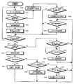
図11には、本実施形態に係る無線ネットワークにおいて、制御局として動作する無線通信装置が実行する動作手順をフローチャートの形式で示している。この動作手順は、実際には、中央制御部67が情報記憶部68に格納されているプログラム・コードを実行するという形態で実現される。
【0094】
まず、無線ネットワークのスーパーフレーム周期を設定する(ステップS1)。
【0095】
さらに、情報受信領域が到来したかどうかを判断する(ステップS2)。そして、情報受信領域が到来していれば、情報受信処理を行なう(ステップS3)。ここでは、隣接する他の無線ネットワークが存在しているかどうかを判断するために、所定の冗長な時間にわたって受信動作を行なうようにしてもよい。
【0096】
次いで、他の無線ネットワークのビーコン信号を受信したかどうかを判断する(ステップS4)。そして、ビーコン信号(図7を参照のこと)を受信していれば、そこに記載されているCAP領域及びCFP領域などのパラメータを獲得する(ステップS5)。そして、後続のステップS9に移行する。
【0097】
一方、情報受信領域において他のネットワークのビーコン信号を受信しなかった場合には、さらに自局宛のコマンドを受信したかどうかを確認する(ステップS6)。
【0098】
ここで、情報受信領域においてコマンドを受信した場合には、中央制御部67にそのコマンド情報を通知し(ステップS7)、そのコマンド情報の処理を行なう。さらに、コマンドが干渉通知(図8を参照のこと)であるかどうかを判断して(ステップS8)、干渉通知であれば、後続のステップS9に移行する。
【0099】
ステップS9では、自ネットワークのスーパーフレーム周期の調整が必要であるかどうかを判断する。この条件として、例えば、自ネットワークのスーパーフレーム周期と他ネットワークのスーパーフレーム周期の位置関係を比較する。
【0100】
そして、自ネットワークのスーパーフレーム周期の調整が必要であると判断された場合には、自己のスーパーフレーム周期に緩衝スーパーフレーム周期を一時的に設定し、その後、ステップS17を介してステップS18において、緩衝スーパーフレーム周期を規定したビーコン信号の送信処理を行なう。
【0101】
一方、ステップS9において、自ネットワークのスーパーフレーム周期の調整が不要であると判断された場合には、さらに、他のネットワーク側でスーパーフレーム周期の調整が必要かどうかを判断する(ステップS11)。この条件としては、例えば、自ネットワークと他のネットワークにおけるネットワークIDの差に基づいて、調整すべきネットワークを決定するようにしてもよい。
【0102】
他のネットワーク側でスーパーフレーム周期の調整が必要であれば、干渉通知コマンド(図8を参照のこと)を作成する(ステップS12)。そして、他のネットワークにおけるCAP領域の到来を待って(ステップS13)、所定のアクセス制御手順に従って当該干渉通知コマンドを送信する(ステップS14)。その後、ステップS17に移行する。
【0103】
また、情報受信領域においてコマンドを受信しなかった場合には(ステップS6)、さらにデータの受信があったかどうかを判断する(ステップS15)。そして、データの受信(図10を参照のこと)があれば、そのデータを無線受信バッファ66に格納して、インターフェース61に受信データを通知する(ステップS16)。その後、ステップS17に移行する。
【0104】
ステップS2で情報受信領域が到来していないと判断された場合、ステップS8で受信コマンドが干渉通知でないと判断された場合、ステップS10で緩衝スーパーフレーム周期を設定した後、ステップS11で他のネットワークの調整が不要と判断された場合、ステップS14で他のネットワークに干渉通知コマンドを送信した後、あるいは、インターフェース61に受信データを通知した後、ステップS17に移行して、自ネットワークにおけるスーパーフレーム周期の先頭のタイミングが到来したかどうかを判断する。
【0105】
そして、そのタイミングが到来した場合にのみ、あらかじめ格納されているビーコン信号を送信し(ステップS18)、その後、ステップS1に移行して所定のスーパーフレーム周期を設定し、上述と同様の一連の動作を繰り返し実行する。
【0106】
また、ステップS17において、スーパーフレーム周期の先頭のタイミングでないと判断された場合には、さらに、インターフェース61側から無線送信する情報が無線送信バッファ62に受理されたかどうかを判断する(ステップS19)。
【0107】
ここで、無線送信する情報を受理した場合には、データ送信が可能なタイミングであるかどうかを判断する(ステップS20)。そして、データ送信可能なタイミングが到来したときに、データ送信処理を行なう(ステップS21)。
【0108】
さらに、無線送信する情報を受理しない場合であっても、その後、ステップS2に移行し、情報受信領域による情報受信処理を行ない、上述と同様の一連の動作を繰り返し実行する
【0109】
また、図12には、本実施形態に係る無線ネットワークにおいて、一般の端末局として動作する無線通信装置が実行する動作手順をフローチャートの形式で示している。この動作手順は、実際には、中央制御部67が情報記憶部68に格納されているプログラム・コードを実行するという形態で実現される。
【0110】
まず、無線ネットワークの制御局からのビーコン信号の受信処理を行なう(ステップS31)。ここでは、無線ネットワークの無線通信装置として動作をする前に、所望の無線ネットワークが存在しているかどうかを判断するために、所定の冗長な時間にわたって受信動作を行なうものとする。
【0111】
次いで、所望の無線ネットワークにおけるビーコン信号の受信があるかどうかを判断する(ステップS32)。ビーコン信号(図7を参照のこと)の受信があれば、スーパーフレーム周期の情報を格納し(ステップS33)、次のビーコン信号受信領域の設定を行なう(ステップS34)。
【0112】
さらに、ビーコン信号の受信領域が到来したかどうかを判断する(ステップS35)。そして、受信領域が到来した場合には、ステップS31に戻って、ビーコン信号の受信処理を繰り返し実行する。つまり、受信できたビーコン信号に記載されているスーパーフレーム周期の情報から、次のビーコン信号受信タイミングを設定する。
【0113】
また、ビーコン信号を受信できない場合には、冗長な時間をビーコン受信領域として設定して(ステップS36)、受信処理を繰り返す。さらに、ビーコン信号の衝突を検出したかどうかを判断する(ステップS37)。ここで、UWB無線データ伝送方式の場合、特定のキャリアが存在しないが、プリアンブル信号を用いることによって衝突を検出することができる。
【0114】
ネットワーク間でのビーコン信号の衝突を検出した場合には、干渉通知コマンドを設定する(ステップS38)。そして、制御局のマネジメント・タイムスロットの領域が到来したときに(ステップS39)、そのタイミングで当該コマンドの送信処理を行なう(ステップS40)。その後、ステップS35(前述)に移行する。
【0115】
また、ステップS37ビーコン信号の衝突を検出しない場合、あるいはステップS39においてマネジメント・タイムスロットの領域でないと判断された場合にも、ステップS35(前述)に移行する。
【0116】
ステップS35において、ビーコン信号の受信領域でないと判断された場合には、次いで、情報受信領域であるかどうかを判断する(ステップS41)。
【0117】
情報受信領域であれば、情報受信処理を行ない(ステップS42)、さらにデータの受信があったかどうかを判断する(ステップS43)。
【0118】
データの受信(図10を参照のこと)があれば、そのデータを無線受信バッファ66に格納し(ステップS44)、インターフェース61に受信データを通知する。その後、ステップS39の処理を介してステップS35に移行して、次のビーコン信号受信領域の到来を判断する。
【0119】
また、ステップS43において、データを受信していないと判断された場合には、コマンドの受信があったかどうかを判断する(ステップS45)。
【0120】
そして、コマンドの受信があれば、そのコマンド情報を中央制御部67に受け渡し(ステップS46)、当該コマンドに従った処理を行なう。その後、ステップS39でマネジメント・タイムスロットが到来したことが確認されたならば、コマンド送信処理に移行する(ステップS40)。
【0121】
また、ステップS45においてコマンドを受信していないと判断された場合には、他のネットワークのビーコン信号を受信したかどうかを判断する(ステップS47)。
【0122】
ここで、他のネットワークのビーコン信号を受信した場合には、干渉通知コマンド(図8を参照のこと)を設定する(ステップS48)。その後、ステップS39でマネジメント・タイムスロットが到来したことが確認されたならば、コマンド送信処理に移行する(ステップS40)。
【0123】
また、ステップS41において情報受信領域でないと判断された場合には、インターフェース61側から無線送信する情報が無線送信バッファ62に受理されたかどうかを判断する(ステップS49)。
【0124】
ここで、無線送信する情報を受理した場合には、データ送信可能なタイミングであるかどうかを判断する(ステップS50)。そして、データ送信可能なタイミングが到来した場合に、データ送信処理が行なわれる(ステップS51)。
【0125】
さらに、無線送信する情報を受理しない場合でも、その後、ステップS39に移行して、マネジメント・タイムスロットでのコマンド送信や、次のビーコン信号受信領域到来の判断に移行し、上述した一連の処理を繰り返し実行する。
【0126】
[追補]
以上、特定の実施形態を参照しながら、本発明について詳解してきた。しかしながら、本発明の要旨を逸脱しない範囲で当業者が該実施形態の修正や代用を成し得ることは自明である。すなわち、例示という形態で本発明を開示してきたのであり、本明細書の記載内容を限定的に解釈するべきではない。本発明の要旨を判断するためには、冒頭に記載した特許請求の範囲の欄を参酌すべきである。
【0127】
【発明の効果】
以上詳記したように、本発明によれば、特定の制御局の管理下で構築される複数のネットワークが好適に共存することができる、優れた無線通信システム、無線通信装置及び無線通信方法、並びにコンピュータ・プログラムを提供することができる。
【0128】
また、本発明によれば、競合するネットワーク間で干渉を避けて運用することができる、優れた無線通信システム、無線通信装置及び無線通信方法、並びにコンピュータ・プログラムを提供することができる。
【0129】
また、本発明によれば、近隣のネットワークからのビーコン信号の送信周期と送信タイミングが重なってしまい、双方のネットワークに存在する無線通信装置がビーコンを検出することができない状況においても、好適にネットワークの運用を行なうことができる、優れた無線通信システム、無線通信装置及び無線通信方法、並びにコンピュータ・プログラムを提供することができる。
【0130】
本発明に係る無線通信システムによれば、緩衝スーパーフレームを一時的に配置することによって、IEEE802.15.3準拠のピコネット運用中にも、他のピコネットとの間に近隣ピコネット(Neighbor Piconet)の関係を構築することができる。
【0131】
あるいは、親ピコネットの制御局(PNC)の指示によって、子ピコネットに割当てられた準静的ギャランティード・タイムスロット(Pseudo-Static GTS)の位置が変化した場合にも、緩衝スーパーフレーム周期を一時的に配置することによって、子ピコネットでは親ピコネットとの同期を獲得することができる。すなわち、所定のスーパーフレーム周期と異なる緩衝スーパーフレーム周期を規定することで、他の無線ネットワークとの間で容易に同期をとることができる。
【0132】
また、本発明に係る無線通信装置によれば、無線ネットワークの制御局に対して干渉の有無の通知を行なうことで、制御局から隠れ端末となる位置にある他の無線ネットワークの存在を知らせることができる。すなわち、制御局からのビーコン信号と、他の無線ネットワークのビーコン信号と衝突している場合に、その状況を制御局宛に通知する。また、無線ネットワークの制御局となる無線通信装置は、他の無線ネットワークの存在通知を受けて、スーパーフレーム周期を微調整することによって、衝突を検出できない制御局はスーパーフレーム周期を微調整して、他の無線通信システムと共存を図ることができる。この結果、安定した無線ネットワームの運用が可能となる。
【0133】
また、本発明に係る無線通信装置によれば、所定のスーパーフレーム周期と異なる緩衝スーパーフレーム周期を1回だけ用いてスーパーフレーム周期を微調整する機能を備えているので、他の無線ネットワークとの間で、容易に同期をとって動作することができる。
【0134】
また、本発明に係る無線通信装置によれば、他の無線ネットワークのビーコン信号を受信したことを制御局に通知する機能を備え、他の無線ネットワークの存在を制御局から指定された領域で制御局あてに通知することにより、制御局から隠れ端末となる位置にある他の無線ネットワークの存在を制御局に知らせることができる。
【0135】
また、本発明に係る無線通信装置によれば、無線ネットワークの制御局からのビーコン信号と他の無線ネットワークからのビーコン信号との衝突を検出し、その衝突発生状況をあらかじめ定められたスーパーフレーム周期の所定の領域を利用して制御局に対して通知を行なうことで、制御局では検出できなかったビーコン信号の衝突を通知することができる。
【図面の簡単な説明】
【図1】同一空間に複数のネットワークが存在している様子を示した図である。
【図2】同一空間に複数のネットワークが存在している様子を示した図である。
【図3】IEEE802.15.3準拠のパーソナル・エリア・ネットワークにおいて利用されるスーパーフレーム周期の構成を模式的に示した図である。
【図4】本実施形態に係る無線ネットワークにおいて使用される緩衝スーパーフレームの配置例を模式的に示した図である。
【図5】本実施形態に係る無線ネットワークにおいて、マネジメント・タイムスロットを利用してビーコン信号の衝突を報告する動作を示した図である。
【図6】本実施形態に係る無線ネットワークで動作することができる無線通信装置の機能構成を模式的に示した図である。
【図7】本実施形態に係る無線ネットワークにおいて使用されるビーコン情報のフレーム構成を模式的に示した図である。
【図8】本実施形態に係る無線ネットワークにおいて、マネジメント・タイムスロットで交換される干渉通知コマンド・フレームの構成を模式的に示した図である。
【図9】本実施形態に係る無線ネットワークにおいて、無線通信装置が制御局に対して帯域予約を要求するために使用する予約要求信号のコマンド・フレームの構成を模式的に示した図である。
【図10】本実施形態に係る無線ネットワークにおいて、無線通信装置間で実際にデータを送るために使用されるデータ情報フレームの構成を模式的に示し
【図11】本実施形態に係る無線ネットワークにおいて、制御局として動作する無線通信装置が実行する動作手順を示したフローチャートである。
【図12】本実施形態に係る無線ネットワークにおいて、制御局に従属して動作する無線通信装置が実行する動作手順を示したフローチャートである。
【符号の説明】
61…インターフェース
62…無線送信バッファ
63…無線送信部
64…アンテナ
65…無線受信部
66…無線受信バッファ
67…中央制御部
68…情報記憶部
69…計時機能部[0001]
BACKGROUND OF THE INVENTION
The present invention relates to a radio communication system, a radio communication apparatus, a radio control method, and a computer program that communicate with each other between a plurality of radio stations, and in particular, a radio in which a network is constructed under the control of a specific control station. The present invention relates to a communication system, a wireless communication apparatus, a wireless communication method, and a computer program.
[0002]
More specifically, the present invention relates to a wireless communication system in which a plurality of wireless networks coexist, a wireless communication apparatus and a wireless communication method for controlling a communication operation in each wireless network in a communication environment in which a plurality of wireless networks compete, and a computer In particular, the present invention relates to a wireless communication system, a wireless communication apparatus and a wireless communication method, and a computer program that operate while avoiding interference between competing networks.
[0003]
[Prior art]
By connecting multiple computers and configuring a LAN (Local Area Network), information such as files and data can be shared, peripheral devices such as printers can be shared, e-mails, data and content can be transferred, etc. Exchange information.
[0004]
Conventionally, it has been common to use an optical fiber, a coaxial cable, or a twisted pair cable to connect to a wired LAN. In this case, however, a line laying work is required, and it is difficult to construct a network easily. The cable routing becomes complicated. In addition, even after LAN construction, the movement range of the device is limited by the cable length, which is inconvenient. Therefore, wireless LANs are attracting attention as a system for releasing users from conventional wired LAN wiring. According to this type of wireless LAN, since most of the wired cables can be omitted in a work space such as an office, a communication terminal such as a personal computer (PC) can be moved relatively easily.
[0005]
In recent years, the demand for wireless LAN systems has increased remarkably with the increase in speed and cost. In particular, recently, in order to establish a small-scale wireless network between a plurality of electronic devices existing around a person and perform information communication, introduction of a personal area network (PAN) has been studied. For example, different wireless communication systems are defined using frequency bands that do not require a license from a supervisory authority, such as 2.4 GHz band and 5 GHz band.
[0006]
For example, in IEEE 802.15.3, standardization activities for high-speed wireless personal area networks exceeding 20 Mbps are underway. In this section, standardization based on the PHY layer mainly using signals in the 2.4 GHz band is promoted.
[0007]
In this type of wireless personal network, one wireless communication device operates as a control station called a "coordinator", and a personal area network is constructed within a range of approximately 10 meters around this coordinator. The The coordinator transmits a beacon signal at a predetermined period, and the period of the beacon is defined as a transmission frame period. A time slot used by each wireless communication device is assigned for each transmission frame period.
[0008]
As a time slot allocation method, for example, a method called “guaranteed time slot” (GTS) is employed, and a communication method for dynamically allocating a transmission band while guaranteeing a predetermined transmission capacity Is assumed.
[0009]
For example, a contention access period (contention access period: CAP) and a non-contention access period (contention free period: CFP) are prepared in the MAC layer standardized by IEEE 802.15.3. . When asynchronous communication is performed, short data and command information are exchanged using the contention access period. On the other hand, when performing stream communication, a dynamic time slot is allocated by a guaranteed time slot (GTS) within a non-contention access period, and band reservation transmission is performed.
[0010]
Note that the MAC layer part standardized by IEEE802.15.3 is defined so that it can be applied as a standard specification of other PHY layers besides the PHY layer using a 2.4 GHz band signal. In addition to the PHY layer that is standardized by IEEE 802.15.3, other than the PHY layer that uses the 2.4 GHz band signal, standardization activities that use other PHY layers are being started.
[0011]
Recently, a wireless LAN system to which an SS (Spread Spectrum) system is applied has been put into practical use. In addition, UWB (Ultra Wide Band) transmission schemes have been proposed for applications such as PAN.
[0012]
The DS (Direct Spread: Direct Spread) method, which is a type of SS method, transmits on the transmitting side by spreading an occupied band by multiplying an information signal by a random code sequence called a PN (Pseudo Noise) code. On the receiving side, the received spread information signal is despread by multiplying it by the PN code to reproduce the information signal.
[0013]
In UWB, an information signal is configured using an impulse signal sequence having a very short period of about several hundred picoseconds, and this signal sequence is transmitted and received. The occupied bandwidth is a band on the order of GHz such that a value obtained by dividing the occupied bandwidth by the center frequency (for example, 1 GHz to 10 GHz) is approximately 1, and is a so-called W-CDMA or cdma2000 system, SS or OFDM ( Compared to a bandwidth normally used in a wireless LAN using an Orthogonal Frequency Division Multiplexing) method, the bandwidth is extremely wide.
[0014]
[Problems to be solved by the invention]
By the way, when information devices such as personal computers (PCs) are widespread, a large number of devices are mixed in an office, and a communication environment in which each device is connected by a wireless network is considered, two or more There may occur a situation in which a wireless network is crowded with a narrow work environment and a plurality of wireless networks coexist in the same frequency band. The “same frequency band” mentioned here includes a UWB wireless communication system that transmits and receives data by spreading data over an extremely wide frequency band.
[0015]
In particular, in the case of a UWB wireless communication network, data is spread and transmitted / received in a very wide band, so there is a high possibility that it will compete with an adjacent wireless communication network.
[0016]
On the other hand, since the impulse signal sequence used in the UWB wireless communication system does not have a specific frequency carrier, it is difficult to perform carrier sense. Therefore, when the UWB wireless communication system is applied as a PHY layer of IEEE802.15.3, there is no specific carrier signal. Therefore, access control can be performed using the carrier sense standardized in the same section. There is no other way but to rely on time-division multiplexing access control.
[0017]
Also, when considering a small-scale wireless network system such as PAN, the existence of each network (base station) is not necessarily fixed, and when a new network is constructed in the same space, There is a need to solve the problem of contention between networks and dynamic allocation of bandwidth (resources) when the network moves from one location to another.
[0018]
In the specification of the PHY layer using the 2.4 GHz band signal standardized by IEEE802.15.3, there are a plurality of other wireless communication systems in the same frequency band. Coexistence must be considered. According to the standardized network configuration, use of a neighbor piconet is considered in which network control stations (PNCs) operate a piconet while avoiding interference with each other. In other words, when an existing control station is transmitting a beacon signal in the same space, a specification is created assuming that another piconet is newly formed.
[0019]
The Neighbor Piconet operation method standardized in IEEE 802.15.3 uses quasi-static guaranteed time slots (Pseudo-Static GTS) to coexist with its own piconet and the other piconet. It is prescribed to plan.
[0020]
Thus, when forming a neighbor piconet (Neighbor Piconet), a conventional method allows a plurality of piconets to be operated on the same frequency by arranging beacon positions in areas separated from each other.
[0021]
However, in the personal area network, another piconet is inevitably formed in the vicinity due to the movement of the piconet, and it is inevitable that the positions of the beacons overlap between the neighboring piconets.
[0022]
Furthermore, if the transmission period and transmission timing of beacon signals overlap between neighboring piconets, the wireless communication device (Device) existing in both piconets can detect the beacon from the control station. The piconet will not be able to be operated at all. Of course, since the control station does not perform the receiving operation when transmitting the beacon signal, it cannot detect itself that it collides with another beacon signal.
[0023]
In addition, with the description content compliant with the IEEE 802.15.3 specification, a wireless communication apparatus that cannot receive a beacon signal cannot grasp the frame structure described in the beacon signal and cannot transmit information by itself. . For this reason, there is no means for wireless communication apparatuses other than the control station to notify the control station of information.
[0024]
In addition, in the operation method of a neighbor piconet compliant with the IEEE 802.15.3 specification, a quasi-static guaranteed time slot (Pseudo-Static GTS) is used, so that the parent piconet (Parent Piconet) There is a possibility that the allocation of guaranteed time slots once set is changed by the control station instruction.
[0025]
The present invention has been made in view of the technical problems as described above, and its main purpose is excellent wireless communication in which a plurality of networks constructed under the control of a specific control station can coexist suitably. A system, a wireless communication apparatus, a wireless communication method, and a computer program are provided.
[0026]
A further object of the present invention is to provide an excellent wireless communication system, wireless communication apparatus and wireless communication method, and computer program that can be operated while avoiding interference between competing networks.
[0027]
A further object of the present invention is to provide a network that is suitable for use even in a situation where the transmission period and transmission timing of beacon signals from neighboring networks overlap, and wireless communication devices existing in both networks cannot detect beacons. An object of the present invention is to provide an excellent wireless communication system, wireless communication apparatus, wireless communication method, and computer program that can be operated.
[0028]
[Means and Actions for Solving the Problems]
The present invention has been made in consideration of the above-mentioned problems. The first aspect of the present invention is from a control station that assigns resources to a plurality of wireless communication apparatuses and each wireless communication apparatus at predetermined transmission frame periods. A wireless communication system in which a plurality of wireless networks coexist,
In response to the detection of interference between the networks, the buffer frame period different from the normal transmission frame period is set in one network to adjust the positional relationship of the frame periods used with each other.
This is a wireless communication system.
[0029]
However, “system” here refers to a logical collection of a plurality of devices (or functional modules that realize specific functions), and each device or functional module is in a single housing. It does not matter whether or not.
[0030]
According to the wireless communication system according to the first aspect of the present invention, when a transmission frame period is shared with a wireless network that is adjacent on the same channel, a buffer frame period that is different from a predetermined frame period Can be used once or temporarily to fine tune the frame period. As a result, it is possible to easily synchronize with other wireless networks.
[0031]
Therefore, according to the wireless communication system according to the first aspect of the present invention, synchronization between adjacent wireless networks is performed so that the non-contention transmission areas do not overlap with each other, and collision of beacon information is avoided. Can build good proximity network relationship.
[0032]
According to the wireless communication system according to the first aspect of the present invention, by temporarily arranging a buffer superframe, a neighboring piconet can be connected to another piconet even during operation of a piconet compliant with IEEE802.15.3. (Neighbor Piconet) relationship can be established.
[0033]
Alternatively, the buffer superframe period is temporarily changed even when the position of the quasi-static guaranteed time slot (Pseudo-Static GTS) assigned to the child piconet is changed according to the instruction of the control station of the parent piconet. By arranging, the child piconet can acquire synchronization with the parent piconet.
[0034]
A second aspect of the present invention is a wireless communication apparatus or a wireless communication method that operates as a control station in a wireless communication environment in which a plurality of wireless networks that operate under the control of the control station coexist.
A beacon transmitting means or step for setting a transmission frame period of the own network and transmitting beacon information related to resource allocation at a predetermined position of the transmission frame period;
Interference detecting means or step for detecting whether the local network interferes with other networks;
In response to detecting interference between networks, a buffer frame period setting means or step for setting a buffer frame period having a different frame period and changing a position of the transmission frame period; and
A wireless communication apparatus or a wireless communication method.
[0035]
Here, the interference detection means or step may detect interference of beacon information based on parameters obtained by receiving beacon information transmitted from another network. For example, the interference detection means or step detects whether or not the non-contention transmission area is synchronized between networks based on parameters obtained by receiving beacon information transmitted from another network. Also good.
[0036]
In such a case, the buffer frame setting means or step sets a buffer frame period shorter than a normal transmission frame period so as to mitigate interference in a non-contention transmission region between networks, and transmits a transmission frame between networks. The period can be easily synchronized.
[0037]
Alternatively, the interference detection means or step may detect interference between networks based on a notification from a wireless communication device in the own network.
[0038]
In such a case, the buffer frame setting means or step sets the buffer frame period shorter than the normal transmission frame period so as to alleviate the collision of the transmission positions of the beacon information between the networks. By synchronizing the transmission frame period, it is possible to avoid collision of beacon information with each other.
[0039]
In other words, a wireless communication device serving as a control station receives a notification of the presence of another wireless network and finely adjusts the transmission frame period of its own network, thereby realizing coexistence of a plurality of wireless networks on the same frequency. it can.
[0040]
Therefore, according to the wireless communication apparatus or method according to the second aspect of the present invention, when a transmission frame period is shared with a wireless network that is adjacent on the same channel, the predetermined frame period is Different buffer frame periods can be used once or temporarily to fine tune the frame period. As a result, it is possible to easily synchronize with other wireless networks. That is, it is possible to establish a good relationship between adjacent networks by synchronizing the adjacent wireless networks so that the non-contention transmission areas do not overlap each other and avoiding collision of beacon information.
[0041]
A third aspect of the present invention is a wireless communication apparatus or a wireless communication method that operates in a specific wireless network in a wireless communication environment in which a plurality of wireless networks that operate under the control of a control station coexist,
Beacon information receiving means or step for receiving beacon information from a control station of its own network in a predetermined beacon information receiving area;
Beacon information detecting means or step for detecting beacon information from a control station of another network;
A collision detection means or step for detecting whether the beacon information of its own network collides with the beacon information of another network;
Interference notification means or step for notifying the control station of the own network of the collision detection result of the beacon information;
A wireless communication apparatus or a wireless communication method.
[0042]
Here, the beacon information detecting means or step may set a redundant time as a beacon information receiving area and detect beacon information from a control station of another network.
[0043]
Further, the interference notification means or step may notify a collision detection result of beacon information using a management time slot assigned to a control station of the own network.
[0044]
When the transmission frame period is shared between networks, a situation in which beacon signals collide with each other may occur. Since the control station does not perform the reception operation when transmitting the beacon signal, it cannot detect itself that it collides with another beacon signal.
[0045]
On the other hand, according to the wireless communication apparatus or the wireless communication method according to the third aspect of the present invention, it is possible to notify the control station that the beacon signals are colliding. For example, the control station can notify the control station of the presence of another wireless network at a position that is a hidden terminal. As a result, a control station that cannot detect a collision can finely adjust the transmission frame period to coexist with other networks.
[0046]
According to a fourth aspect of the present invention, there is provided a computer-readable program for executing a process for operating as a control station on a computer system in a wireless communication environment in which a plurality of wireless networks operating under the control of the control station coexist. A computer program written in a format,
A beacon transmission step of setting a transmission frame period of the own network and transmitting beacon information related to resource allocation at a predetermined position of the transmission frame period;
An interference detection step for detecting whether the local network interferes with other networks;
In response to detecting interference between networks, a buffer frame cycle setting step for setting a buffer frame cycle having a different frame cycle and changing a position of the transmission frame cycle;
A computer program characterized by comprising:
[0047]
According to a fifth aspect of the present invention, a process for operating in a specific wireless network is executed on a computer system in a wireless communication environment in which a plurality of wireless networks operating under the control of a control station coexist. A computer program written in a computer readable format,
A beacon information receiving step for receiving beacon information from a control station of the own network in a predetermined beacon information receiving area;
A beacon information detection step of detecting beacon information from a control station of another network;
A collision detection step for detecting whether the beacon information of the own network collides with the beacon information of another network;
An interference notification step for notifying the control station of the local network of the collision detection result of the beacon information;
A computer program characterized by comprising:
[0048]
The computer program according to each of the fourth and fifth aspects of the present invention defines a computer program written in a computer-readable format so as to realize predetermined processing on a computer system. In other words, by installing the computer program according to the fourth or fifth aspect of the present invention in the computer system, a cooperative action is exhibited on the computer system, and the second or second aspect of the present invention is achieved. The same effects as those of the wireless communication apparatus or the wireless communication method according to the third aspect can be obtained.
[0049]
Other objects, features, and advantages of the present invention will become apparent from more detailed description based on embodiments of the present invention described later and the accompanying drawings.
[0050]
DETAILED DESCRIPTION OF THE INVENTION
Hereinafter, embodiments of the present invention will be described in detail with reference to the drawings.
[0051]
FIG. 1 shows a state where a plurality of networks exist in the same space.
[0052]
In the example shown in the figure, the first piconet 1 is formed by
[0053]
Similarly, the
[0054]
Here, the control station devices (PNCs) 10 and 20 of both piconets and the
[0055]
FIG. 2 shows another example in which a plurality of networks exist in the same space.
[0056]
In the example shown in the figure, the first piconet 1 is formed by
[0057]
Similarly, the
[0058]
Here, the
[0059]
The wireless network referred to here performs wireless data communication by, for example, a UWB (Ultra Wide Band) transmission method. In the case of a UWB wireless communication network, data is spread and transmitted / received in a very wide band, so there is a high possibility that it will compete with an adjacent wireless communication network. In addition, since the impulse signal sequence used in the UWB wireless communication system does not have a specific frequency carrier and it is difficult to perform carrier sense, access control is performed by time division multiplexing.
[0060]
FIG. 3 schematically shows the configuration of a superframe period used in a personal area network compliant with IEEE 802.15.3.
[0061]
As shown in the figure, the superframe period is determined by a beacon. Subsequently to the beacon, a contention transmission period (CAP) that is a contention transmission area and a contention free period (CFP) that is a non-contention transmission area are arranged.
[0062]
Here, the Content Access Period (CAP) stipulates that asynchronous wireless communication using a random access mechanism by CSMA / CA is performed, for example.
[0063]
In addition, the Content Free Period (CFP) includes an area for exchanging commands between a communication device serving as a control station in the network called Management Time Slot (MTS) and each communication device, and a Guaranteeed Time Slot (GTS). An area where bandwidth reservation / allocation communication is performed is appropriately arranged for each superframe as necessary.
[0064]
In the personal area network conforming to IEEE 802.15.3, the network is operated by repeatedly using the illustrated superframe period.
[0065]
FIG. 4 schematically shows an arrangement example of buffer superframes used in the wireless network according to the present embodiment. However, in the illustrated example, the relationship between the first piconet and the second piconet in the case where they are adjacent to each other is shown.
[0066]
As illustrated, the superframe periods 411 and 412 of the first piconet and the
[0067]
Here, the control station of the second piconet that has detected that the synchronization is not established temporarily arranges the
[0068]
At this time, the control station of the second piconet sets a guaranteed time slot GTS (the hatched portion in the figure) so that the first piconet operates as a neighbor piconet.
[0069]
In response, the control station of the first piconet performs a guaranteed time slot so that the second piconet operates as a neighbor piconet in the
[0070]
Thereafter, by setting mutually guaranteed time slots GTS as in the
[0071]
FIG. 5 shows an operation of reporting a beacon signal collision using a management time slot in the wireless network according to the present embodiment. However, in the illustrated example, the relationship between the first piconet and the second piconet in the case where they are adjacent to each other is shown.
[0072]
As shown in the figure, the
[0073]
Here, the communication device included in the second piconet that has detected a beacon collision notifies the control station of the second piconet using the management time slot M.
[0074]
The control station of the second piconet that has received the notification of the beacon collision in the management time slot M builds a relationship between neighboring piconets by temporarily placing the
[0075]
At this time, the control station of the second piconet sets a guaranteed time slot GTS (the hatched portion in the figure) so that the first piconet operates as a neighbor piconet.
[0076]
In response, the control station of the first piconet operates in a guaranteed time slot so that the second piconet operates as a neighbor piconet in the
[0077]
Thereafter, as in the
[0078]
FIG. 6 schematically shows a functional configuration of a wireless communication apparatus that can operate in the wireless network according to the present embodiment.
[0079]
As illustrated, the wireless communication device includes an interface 61 for exchanging information with a device (application) connected to the device, a wireless transmission buffer 62 for storing information delivered from the application via the interface 61, A
[0080]
This wireless communication apparatus further includes a function as a control station. That is, when an operation as a control station is necessary, an execution command program is stored in advance in the information storage unit 68 so as to operate as a control station as appropriate, or as a general wireless communication apparatus.
[0081]
The wireless communication device operating as a control station creates beacon information in the
[0082]
The wireless communication device that is not the control station receives a beacon signal from the control station at the
[0083]
These wireless communication devices are configured to operate in accordance with a predetermined access control method, and each wireless communication device transmits command information to the control station in the management time slot (MTS) region of the superframe period. can do. That is, the control station performs a reception operation in the management time slot (MTS) area and receives command information from each wireless communication device.
[0084]
Also, commands exchanged in the management time slot area include a command for reserving a guaranteed time slot (GTS) for performing reserved bandwidth transmission in a non-contention transmission area, and other wireless networks in the vicinity. A command or the like for notifying that there exists is prepared.
[0085]
FIG. 7 schematically shows a frame configuration of beacon information used in the wireless network according to the present embodiment.
[0086]
As shown in the figure, the beacon information frame operates a network including header information (Beacon Header) 71 indicating a beacon signal, a header check sequence (Header Check) 72 for confirming whether there is an error in the header information, and the network. Identification information (Device Identifier) 73 of the communication device for identifying a device that is connected, synchronization parameter information 74 necessary for operating the network, maximum transmission power information 75 indicating the maximum transmission power in the network, The channel reservation allocation information 76 of the non-contention transmission area (CFP) band reservation communication, and a frame check sequence 77 for checking whether or not there is an error in the frame information. Is done.
[0087]
FIG. 8 schematically shows the configuration of an interference notification command frame exchanged in the management time slot.
[0088]
As shown in the figure, the interference notification command frame includes header information (Command Header) 81 indicating that it is an interference notification command, and a header check sequence (Header Check) 82 for confirming whether or not there is an error in the header information. And an interference notification element (Coexistence Information Element) 83 in which parameters for performing interference notification from other wireless networks are described, and a frame check sequence (Frame Check) 84 for confirming whether there is an error in the frame information. Is done.
[0089]
FIG. 9 schematically shows the configuration of a command frame of a reservation request signal that is used by the wireless communication apparatus to request bandwidth reservation from the control station in the wireless network according to the present embodiment. .
[0090]
As shown in the figure, the command frame of the reservation request signal includes header information (Command Header) 91 indicating that the command is a reservation request command, and a header check sequence (Header) for confirming whether there is an error in the header information. (Check) 92, a bandwidth reservation information element (Channel Time Request Block) 93 in which parameters for requesting bandwidth reservation are described, and a frame check sequence (Frame Check) 94 for confirming whether or not there is an error in the frame information. Composed.
[0091]
FIG. 10 schematically shows the configuration of a data information frame used for actually transmitting data between wireless communication devices in the wireless network according to the present embodiment.
[0092]
As shown in the figure, the data information frame includes header information (Data Header) 101 indicating that it is data, a header check sequence (Header Check) 102 for confirming whether there is an error in the header information, and actually It consists of an information data payload 103 as user data and a
[0093]
FIG. 11 shows, in the form of a flowchart, an operation procedure executed by a wireless communication apparatus operating as a control station in the wireless network according to the present embodiment. This operation procedure is actually realized in a form in which the
[0094]
First, the superframe period of the wireless network is set (step S1).
[0095]
Further, it is determined whether an information reception area has arrived (step S2). If the information reception area has arrived, information reception processing is performed (step S3). Here, in order to determine whether or not another adjacent wireless network exists, the reception operation may be performed over a predetermined redundant time.
[0096]
Next, it is determined whether or not a beacon signal from another wireless network has been received (step S4). And if the beacon signal (refer FIG. 7) is received, parameters, such as a CAP area | region and CFP area | region described there, will be acquired (step S5). Then, the process proceeds to subsequent step S9.
[0097]
On the other hand, if a beacon signal from another network has not been received in the information reception area, it is further confirmed whether a command addressed to the own station has been received (step S6).
[0098]
When a command is received in the information receiving area, the command information is notified to the central control unit 67 (step S7), and the command information is processed. Further, it is determined whether or not the command is an interference notification (see FIG. 8) (step S8). If the command is an interference notification, the process proceeds to the subsequent step S9.
[0099]
In step S9, it is determined whether it is necessary to adjust the superframe period of the own network. As this condition, for example, the positional relationship between the superframe period of the own network and the superframe period of another network is compared.
[0100]
If it is determined that the superframe period of the own network needs to be adjusted, the buffer superframe period is temporarily set to the own superframe period, and then in step S18 via step S17, A beacon signal transmission process defining the buffer superframe period is performed.
[0101]
On the other hand, if it is determined in step S9 that adjustment of the superframe cycle of the own network is unnecessary, it is further determined whether adjustment of the superframe cycle is necessary on the other network side (step S11). As this condition, for example, a network to be adjusted may be determined based on a difference in network ID between the local network and another network.
[0102]
If the superframe period needs to be adjusted on the other network side, an interference notification command (see FIG. 8) is created (step S12). Then, after waiting for the arrival of the CAP area in another network (step S13), the interference notification command is transmitted according to a predetermined access control procedure (step S14). Thereafter, the process proceeds to step S17.
[0103]
If no command is received in the information receiving area (step S6), it is further determined whether or not data has been received (step S15). If data is received (see FIG. 10), the data is stored in the wireless reception buffer 66 and the received data is notified to the interface 61 (step S16). Thereafter, the process proceeds to step S17.
[0104]
If it is determined in step S2 that the information reception area has not arrived, or if it is determined in step S8 that the received command is not an interference notification, a buffer superframe period is set in step S10, and then another network is determined in step S11. Is determined to be unnecessary, after transmitting an interference notification command to another network in step S14 or notifying the interface 61 of received data, the process proceeds to step S17, and the superframe period in the own network is determined. It is determined whether or not the timing of the head of has arrived.
[0105]
Only when the timing has arrived, a pre-stored beacon signal is transmitted (step S18), and then the process proceeds to step S1 to set a predetermined superframe period, and a series of operations similar to those described above Repeatedly.
[0106]
If it is determined in step S17 that the timing is not the head timing of the superframe period, it is further determined whether or not the wireless transmission buffer 62 has received information for wireless transmission from the interface 61 side (step S19).
[0107]
Here, when the information to be transmitted wirelessly is accepted, it is determined whether or not it is the timing at which data transmission is possible (step S20). Then, when it is time to transmit data, data transmission processing is performed (step S21).
[0108]
Further, even if the information to be transmitted wirelessly is not accepted, the process thereafter proceeds to step S2, information reception processing is performed by the information reception area, and a series of operations similar to those described above are repeatedly executed.
[0109]
FIG. 12 shows an operation procedure executed by a wireless communication apparatus operating as a general terminal station in the form of a flowchart in the wireless network according to the present embodiment. This operation procedure is actually realized in a form in which the
[0110]
First, a reception process of a beacon signal from a control station of a wireless network is performed (step S31). Here, it is assumed that the reception operation is performed over a predetermined redundant time in order to determine whether or not a desired wireless network exists before operating as a wireless communication device of the wireless network.
[0111]
Next, it is determined whether or not a beacon signal is received in the desired wireless network (step S32). If a beacon signal (see FIG. 7) is received, superframe period information is stored (step S33), and the next beacon signal reception area is set (step S34).
[0112]
Further, it is determined whether or not a beacon signal reception area has arrived (step S35). If the reception area has arrived, the process returns to step S31 to repeatedly execute the beacon signal reception process. That is, the next beacon signal reception timing is set from the information of the superframe period described in the received beacon signal.
[0113]
If the beacon signal cannot be received, a redundant time is set as the beacon reception area (step S36), and the reception process is repeated. Further, it is determined whether or not a beacon signal collision is detected (step S37). Here, in the case of the UWB wireless data transmission system, a specific carrier does not exist, but a collision can be detected by using a preamble signal.
[0114]
When a collision of beacon signals between networks is detected, an interference notification command is set (step S38). Then, when the management time slot area of the control station arrives (step S39), transmission processing of the command is performed at that timing (step S40). Thereafter, the process proceeds to step S35 (described above).
[0115]
Also, if no collision of the beacon signal in step S37 is detected, or if it is determined in step S39 that it is not the management time slot area, the process proceeds to step S35 (described above).
[0116]
If it is determined in step S35 that it is not a beacon signal reception area, it is then determined whether it is an information reception area (step S41).
[0117]
If it is an information reception area, information reception processing is performed (step S42), and it is further determined whether or not data has been received (step S43).
[0118]
If data is received (see FIG. 10), the data is stored in the wireless reception buffer 66 (step S44), and the received data is notified to the interface 61. Thereafter, the process proceeds to step S35 via the process of step S39, and the arrival of the next beacon signal reception area is determined.
[0119]
If it is determined in step S43 that no data has been received, it is determined whether a command has been received (step S45).
[0120]
If a command is received, the command information is transferred to the central control unit 67 (step S46), and processing according to the command is performed. Thereafter, if it is confirmed in step S39 that a management time slot has arrived, the process proceeds to command transmission processing (step S40).
[0121]
If it is determined in step S45 that no command has been received, it is determined whether a beacon signal from another network has been received (step S47).
[0122]
When a beacon signal from another network is received, an interference notification command (see FIG. 8) is set (step S48). Thereafter, if it is confirmed in step S39 that a management time slot has arrived, the process proceeds to command transmission processing (step S40).
[0123]
If it is determined in step S41 that it is not the information reception area, it is determined whether or not the information to be wirelessly transmitted from the interface 61 side is received by the wireless transmission buffer 62 (step S49).
[0124]
Here, when the information to be wirelessly transmitted is accepted, it is determined whether or not it is the timing at which data transmission is possible (step S50). Then, when the timing for data transmission has arrived, data transmission processing is performed (step S51).
[0125]
Further, even when the information to be transmitted wirelessly is not accepted, the process proceeds to step S39, where the process proceeds to the command transmission in the management time slot and the determination of the arrival of the next beacon signal reception area. Run repeatedly.
[0126]
[Supplement]
The present invention has been described in detail above with reference to specific embodiments. However, it is obvious that those skilled in the art can make modifications and substitutions of the embodiment without departing from the gist of the present invention. That is, the present invention has been disclosed in the form of exemplification, and the contents described in the present specification should not be interpreted in a limited manner. In order to determine the gist of the present invention, the claims section described at the beginning should be considered.
[0127]
【The invention's effect】
As described in detail above, according to the present invention, an excellent wireless communication system, wireless communication apparatus, and wireless communication method, in which a plurality of networks constructed under the control of a specific control station can coexist suitably, In addition, a computer program can be provided.
[0128]
Furthermore, according to the present invention, it is possible to provide an excellent wireless communication system, wireless communication apparatus, wireless communication method, and computer program that can be operated while avoiding interference between competing networks.
[0129]
In addition, according to the present invention, even in a situation where the transmission cycle and transmission timing of beacon signals from neighboring networks overlap and wireless communication devices existing in both networks cannot detect the beacon, An excellent wireless communication system, wireless communication apparatus and wireless communication method, and computer program can be provided.
[0130]
According to the wireless communication system of the present invention, by temporarily arranging a buffer superframe, even during operation of an IEEE 802.15.3 compliant piconet, a neighbor piconet can be connected to another piconet. You can build relationships.
[0131]
Alternatively, even if the position of the quasi-static guaranteed time slot (Pseudo-Static GTS) assigned to the child piconet changes according to the instruction of the control station (PNC) of the parent piconet, the buffer superframe period is temporarily Thus, the child piconet can acquire synchronization with the parent piconet. That is, by defining a buffer superframe period different from the predetermined superframe period, it is possible to easily synchronize with other wireless networks.
[0132]
In addition, according to the wireless communication device of the present invention, the presence or absence of interference is notified from the control station to the control station of the wireless network, so that the presence of another wireless network in the position to be a hidden terminal is notified from the control station. Can do. That is, when there is a collision with a beacon signal from a control station and a beacon signal of another wireless network, the situation is notified to the control station. In addition, a wireless communication device that is a control station of a wireless network receives a notification of the presence of another wireless network and finely adjusts the superframe period, so that a control station that cannot detect a collision finely adjusts the superframe period. Coexistence with other wireless communication systems can be achieved. As a result, stable wireless network operation is possible.
[0133]
Further, according to the wireless communication apparatus according to the present invention, since it has a function of finely adjusting the superframe period by using a buffer superframe period different from the predetermined superframe period only once, It is possible to operate in synchronization with each other easily.
[0134]
In addition, the wireless communication apparatus according to the present invention has a function of notifying the control station that a beacon signal of another wireless network has been received, and controls the presence of the other wireless network in an area designated by the control station. By notifying the station, it is possible to notify the control station of the presence of another wireless network in the position to be a hidden terminal from the control station.
[0135]
Further, according to the wireless communication device of the present invention, a collision between a beacon signal from a control station of a wireless network and a beacon signal from another wireless network is detected, and the occurrence of the collision is determined in a predetermined superframe cycle. By using this predetermined area to notify the control station, it is possible to notify a collision of beacon signals that could not be detected by the control station.
[Brief description of the drawings]
FIG. 1 is a diagram showing a state in which a plurality of networks exist in the same space.
FIG. 2 is a diagram showing a state in which a plurality of networks exist in the same space.
FIG. 3 is a diagram schematically showing a configuration of a superframe period used in a personal area network compliant with IEEE 802.15.3.
FIG. 4 is a diagram schematically illustrating an arrangement example of buffer superframes used in the wireless network according to the present embodiment.
FIG. 5 is a diagram illustrating an operation of reporting a beacon signal collision using a management time slot in the wireless network according to the present embodiment.
FIG. 6 is a diagram schematically illustrating a functional configuration of a wireless communication apparatus that can operate in a wireless network according to the present embodiment.
FIG. 7 is a diagram schematically showing a frame configuration of beacon information used in the wireless network according to the present embodiment.
FIG. 8 is a diagram schematically showing a configuration of an interference notification command frame exchanged in a management time slot in the wireless network according to the present embodiment.
FIG. 9 is a diagram schematically showing a configuration of a command frame of a reservation request signal that is used by a wireless communication apparatus to request a bandwidth reservation from a control station in the wireless network according to the present embodiment.
FIG. 10 schematically shows a configuration of a data information frame used for actually transmitting data between wireless communication devices in the wireless network according to the present embodiment.
FIG. 11 is a flowchart showing an operation procedure executed by a wireless communication apparatus operating as a control station in the wireless network according to the present embodiment.
FIG. 12 is a flowchart showing an operation procedure executed by a wireless communication apparatus that operates depending on a control station in the wireless network according to the present embodiment.
[Explanation of symbols]
61 ... Interface
62 ... Wireless transmission buffer
63: Wireless transmission unit
64 ... Antenna
65 ... Wireless receiver
66 ... Wireless reception buffer
67 ... Central control unit
68. Information storage unit
69 ... Timekeeping function section
Claims (17)
ネットワーク間で干渉が検出されたことに応答して、一方のネットワークにおいて通常の伝送フレーム周期とは長さの異なる緩衝フレーム周期を一時的に設定して互いに利用する伝送フレーム周期の位置関係を調整するとともに、それぞれの伝送フレーム周期内において非競合伝送領域が重ならないように設定する、
ことを特徴とする無線通信システム。A wireless communication system in which a plurality of wireless networks including a plurality of wireless communication devices and a control station that assigns resources to each wireless communication device every transmission frame cycle of a predetermined length coexists, and the transmission frame cycle is a bandwidth reservation / allocation Including a non-contention transmission area for data communication based on
In response to the detection of interference between networks, the buffer frame period that is different from the normal transmission frame period in one network is temporarily set to adjust the positional relationship of the transmission frame periods that are used mutually. And set so that non-contention transmission areas do not overlap within each transmission frame period,
A wireless communication system.
ネットワーク間で干渉が検出されたことに応答して、一方のネットワークにおいて通常の伝送フレーム周期とは長さの異なる緩衝フレーム周期を一時的に設定して、各制御局のビーコン信号が衝突しないように、互いに利用する伝送フレーム周期の位置関係を調整する、In response to the detection of interference between networks, a buffer frame period that is different in length from the normal transmission frame period is temporarily set in one network so that the beacon signals of each control station do not collide. Adjusting the positional relationship of the transmission frame periods used mutually,
ことを特徴とする無線通信システム。A wireless communication system.
自ネットワークにおいて、帯域予約/割当てに基づいてデータ通信を行なう非競合伝送領域を含んだ所定長の伝送フレーム周期を設定する伝送フレーム周期設定手段と、Transmission frame period setting means for setting a transmission frame period of a predetermined length including a non-contention transmission area for performing data communication based on bandwidth reservation / allocation in the own network;
該伝送フレーム周期の所定位置にて資源割当てに関するビーコン情報を送信するビーコン送信手段と、Beacon transmitting means for transmitting beacon information related to resource allocation at a predetermined position in the transmission frame period;
自ネットワークが他のネットワークと干渉するかどうかを検出する干渉検出手段と、Interference detection means for detecting whether or not the own network interferes with other networks;
ネットワーク間の干渉を検出したことに応答して、前記伝送フレーム周期とは長さの異なる緩衝フレーム周期を一時的に設定して、該干渉したネットワークとの間で互いに利用する伝送フレーム周期の位置関係を調整するとともに、それぞれの伝送フレーム周期内において非競合伝送領域が重ならないように設定する緩衝フレーム周期設定手段と、In response to detecting interference between networks, a buffer frame period having a length different from that of the transmission frame period is temporarily set, and positions of transmission frame periods that are mutually used with the interfered network Buffer frame period setting means for adjusting the relationship and setting so that non-contention transmission areas do not overlap in each transmission frame period;
を具備することを特徴とする無線通信装置。A wireless communication apparatus comprising:
自ネットワークの所定長の伝送フレーム周期を設定して、該伝送フレーム周期の所定位置にて資源割当てに関するビーコン情報を伝送フレーム周期の所定位置で送信するビーコン送信手段と、Beacon transmitting means for setting a transmission frame period of a predetermined length of the own network and transmitting beacon information related to resource allocation at a predetermined position of the transmission frame period at a predetermined position of the transmission frame period;
自ネットワークが他のネットワークと干渉するかどうかを検出する干渉検出手段と、Interference detection means for detecting whether or not the own network interferes with other networks;
ネットワーク間の干渉を検出したことに応答して、前記伝送フレーム周期とは長さの異なる緩衝フレーム周期を一時的に設定して、各制御局のビーコン信号が衝突しないように、該干渉したネットワークとの間で互いに利用する伝送フレーム周期の位置関係を調整する緩衝フレーム周期設定手段と、In response to detecting interference between the networks, a buffer frame period having a length different from the transmission frame period is temporarily set so that the beacon signals of the control stations do not collide with each other. A buffer frame period setting means for adjusting a positional relationship of transmission frame periods to be used with each other;
を具備することを特徴とする無線通信装置。A wireless communication apparatus comprising:
前記緩衝フレーム周期設定手段は、前記判定手段により自己の伝送フレーム周期の調整が必要と判定された場合に、前記緩衝フレーム周期を一時的に設定する、The buffer frame period setting means temporarily sets the buffer frame period when the determination means determines that adjustment of its own transmission frame period is necessary.
ことを特徴とする請求項3又は4のいずれかに記載の無線通信装置。The wireless communication device according to claim 3, wherein the wireless communication device is a wireless communication device.
ことを特徴とする請求項3又は4のいずれかに記載の無線通信装置。The wireless communication device according to claim 3, wherein the wireless communication device is a wireless communication device.
ことを特徴とする請求項4に記載の無線通信装置。The wireless communication apparatus according to claim 4.
前記干渉検出手段は、他のネットワークから送信されるビーコン情報を受信して得たパラメータを基に、ネットワーク間で非競合伝送領域の同期がとれているかどうかを検出する、The interference detection means detects whether or not a non-contention transmission area is synchronized between networks based on parameters obtained by receiving beacon information transmitted from another network.
ことを特徴とする請求項3に記載の無線通信装置。The wireless communication apparatus according to claim 3.
ことを特徴とする請求項8に記載の無線通信装置。The wireless communication apparatus according to claim 8.
ことを特徴とする請求項3又は4のいずれかに記載の無線通信装置。The wireless communication device according to claim 3, wherein the wireless communication device is a wireless communication device.
ことを特徴とする請求項4に記載の無線通信装置。The wireless communication apparatus according to claim 4.
自ネットワークにおいて、帯域予約/割当てに基づいてデータ通信を行なう非競合伝送領域を含んだ所定長の伝送フレーム周期を設定する伝送フレーム周期設定ステップと、A transmission frame period setting step for setting a transmission frame period of a predetermined length including a non-contention transmission area for performing data communication based on bandwidth reservation / allocation in the own network;
該伝送フレーム周期の所定位置にて資源割当てに関するビーコン情報を送信するビーコン送信ステップと、A beacon transmission step of transmitting beacon information related to resource allocation at a predetermined position in the transmission frame period;
自ネットワークが他のネットワークと干渉するかどうかを検出する干渉検出ステップと、An interference detection step for detecting whether the local network interferes with other networks;
ネットワーク間の干渉を検出したことに応答して、前記伝送フレーム周期とは長さの異なる緩衝フレーム周期を一時的に設定して、該干渉したネットワークとの間で互いに利用する伝送フレーム周期の位置関係を調整するとともに、それぞれの伝送フレーム周期内において非競合伝送領域が重ならないように設定する緩衝フレーム周期設定ステップと、In response to detecting interference between networks, a buffer frame period having a length different from that of the transmission frame period is temporarily set, and positions of transmission frame periods that are mutually used with the interfered network A buffer frame period setting step for adjusting the relationship and setting so that non-contention transmission areas do not overlap within each transmission frame period;
を具備することを特徴とする無線通信方法。A wireless communication method comprising:
自ネットワークの所定長の伝送フレーム周期を設定して、該伝送フレーム周期の所定位置にて資源割当てに関するビーコン情報を伝送フレーム周期の所定位置で送信するビーコン送信ステップと、A beacon transmission step of setting a transmission frame period of a predetermined length of the own network and transmitting beacon information related to resource allocation at a predetermined position of the transmission frame period at a predetermined position of the transmission frame period;
自ネットワークが他のネットワークと干渉するかどうかを検出する干渉検出ステップとAn interference detection step for detecting whether the local network interferes with other networks; 、,
ネットワーク間の干渉を検出したことに応答して、前記伝送フレーム周期とは長さの異なる緩衝フレーム周期を一時的に設定して、各制御局のビーコン信号が衝突しないように、該干渉したネットワークとの間で互いに利用する伝送フレーム周期の位置関係を調整する緩衝フレーム周期設定ステップと、In response to detecting interference between networks, a buffer frame period having a length different from the transmission frame period is temporarily set so that the beacon signals of the control stations do not collide with each other. A buffer frame period setting step for adjusting a positional relationship of transmission frame periods used with each other;
を具備することを特徴とする無線通信方法。A wireless communication method comprising:
所定のビーコン情報受信領域において自ネットワークの制御局からのビーコン情報を受信するビーコン情報受信手段と、Beacon information receiving means for receiving beacon information from a control station of the own network in a predetermined beacon information receiving area;
他のネットワークの制御局からのビーコン情報を検出するビーコン情報検出手段と、Beacon information detecting means for detecting beacon information from a control station of another network;
自ネットワークのビーコン情報が他のネットワークのビーコン情報と衝突するかどうかを検出する衝突検出手段と、A collision detection means for detecting whether the beacon information of the own network collides with the beacon information of another network;
ビーコン情報の衝突検出結果を自ネットワークの制御局に通知する干渉通知手段と、An interference notification means for notifying the control station of the own network of the collision detection result of the beacon information;
を具備することを特徴とする無線通信装置。A wireless communication apparatus comprising:
ことを特徴とする請求項14に記載の無線通信装置。The wireless communication apparatus according to claim 14.
ことを特徴とする請求項14に記載の無線通信装置。The wireless communication apparatus according to claim 14.
所定のビーコン情報受信領域において自ネットワークの制御局からのビーコン情報を受信するビーコン情報受信ステップと、A beacon information receiving step for receiving beacon information from a control station of the own network in a predetermined beacon information receiving area;
他のネットワークの制御局からのビーコン情報を検出するビーコン情報検出ステップと、A beacon information detection step of detecting beacon information from a control station of another network;
自ネットワークのビーコン情報が他のネットワークのビーコン情報と衝突するかどうかを検出する衝突検出ステップと、A collision detection step for detecting whether the beacon information of the own network collides with the beacon information of another network;
ビーコン情報の衝突検出結果を自ネットワークの制御局に通知する干渉通知ステップと、An interference notification step for notifying the control station of the local network of the collision detection result of the beacon information;
を具備することを特徴とする無線通信方法。A wireless communication method comprising:
Priority Applications (3)
| Application Number | Priority Date | Filing Date | Title |
|---|---|---|---|
| JP2002197509A JP3968514B2 (en) | 2002-07-05 | 2002-07-05 | Wireless communication system, wireless communication apparatus, wireless communication method, and computer program |
| US10/600,749 US7664030B2 (en) | 2002-07-05 | 2003-06-19 | Radio communication system, radio communication apparatus, radio communication method, and computer program |
| US12/651,677 US7957290B2 (en) | 2002-07-05 | 2010-01-04 | Radio communication system, radio communication apparatus, and radio communication method |
Applications Claiming Priority (1)
| Application Number | Priority Date | Filing Date | Title |
|---|---|---|---|
| JP2002197509A JP3968514B2 (en) | 2002-07-05 | 2002-07-05 | Wireless communication system, wireless communication apparatus, wireless communication method, and computer program |
Publications (3)
| Publication Number | Publication Date |
|---|---|
| JP2004040645A JP2004040645A (en) | 2004-02-05 |
| JP2004040645A5 JP2004040645A5 (en) | 2005-03-17 |
| JP3968514B2 true JP3968514B2 (en) | 2007-08-29 |
Family
ID=31705265
Family Applications (1)
| Application Number | Title | Priority Date | Filing Date |
|---|---|---|---|
| JP2002197509A Expired - Fee Related JP3968514B2 (en) | 2002-07-05 | 2002-07-05 | Wireless communication system, wireless communication apparatus, wireless communication method, and computer program |
Country Status (2)
| Country | Link |
|---|---|
| US (2) | US7664030B2 (en) |
| JP (1) | JP3968514B2 (en) |
Families Citing this family (71)
| Publication number | Priority date | Publication date | Assignee | Title |
|---|---|---|---|---|
| US7817612B2 (en) * | 2003-07-29 | 2010-10-19 | Sony Corporation | Decentralized wireless communication system, apparatus, and associated methodology |
| US7346021B2 (en) | 2003-08-06 | 2008-03-18 | Matsushita Electric Industrial Co., Ltd. | Master station in communications system and access control method |
| JP3905534B2 (en) * | 2003-09-18 | 2007-04-18 | 三星電子株式会社 | Method and system for efficiently communicating between a child PNC and a target device |
| ES2377648T3 (en) * | 2003-11-07 | 2012-03-29 | Sharp Kabushiki Kaisha | Method for frequency and time division access |
| US8213301B2 (en) * | 2003-11-07 | 2012-07-03 | Sharp Laboratories Of America, Inc. | Systems and methods for network channel characteristic measurement and network management |
| US8208449B2 (en) * | 2004-01-05 | 2012-06-26 | Broadcom Corporation | Multi-mode WLAN/PAN MAC |
| WO2005076544A1 (en) * | 2004-02-06 | 2005-08-18 | Koninklijke Philips Electronics, N.V. | A system and method for an ultra wide-band medium access control distributed reservation protocol |
| JP4692017B2 (en) * | 2004-03-01 | 2011-06-01 | ソニー株式会社 | Wireless communication system, wireless communication apparatus, wireless communication method, and computer program |
| US7664130B2 (en) | 2004-03-01 | 2010-02-16 | Sony Corporation | Wireless communication system, wireless communication apparatus, wireless communication method and computer program |
| JP4506282B2 (en) * | 2004-05-26 | 2010-07-21 | ソニー株式会社 | Wireless communication method, wireless communication device, and computer-readable program |
| JP4428143B2 (en) * | 2004-05-28 | 2010-03-10 | ソニー株式会社 | COMMUNICATION DEVICE, COMMUNICATION METHOD, AND PROGRAM |
| JP4779438B2 (en) * | 2004-05-31 | 2011-09-28 | パナソニック株式会社 | Wireless communication method and wireless communication apparatus |
| JP4449588B2 (en) * | 2004-06-09 | 2010-04-14 | ソニー株式会社 | Wireless communication system, wireless communication apparatus, wireless communication method, and computer program |
| WO2005125047A1 (en) * | 2004-06-16 | 2005-12-29 | Philips Intellectual Property & Standards Gmbh | Distributed resource reservation in a wireless adhoc network |
| JP4271089B2 (en) | 2004-06-17 | 2009-06-03 | パナソニック株式会社 | Wireless communication method and wireless communication apparatus |
| US7385958B2 (en) * | 2004-06-30 | 2008-06-10 | Intel Corporation | Ad hoc mode of operation in wireless personal area networks |
| US7508811B2 (en) * | 2004-07-10 | 2009-03-24 | Mitsubishi Electric Research Laboratories, Inc. | Beacon scheduling in wireless personal area networks with multiple coordinators |
| EP1782578B1 (en) * | 2004-08-12 | 2015-05-27 | InterDigital Technology Corporation | Method and access point for controlling access to a wireless communication medium |
| US7254399B2 (en) * | 2004-10-12 | 2007-08-07 | Nokia Corporation | Techniques for interference reduction in wireless communications networks |
| US8023473B2 (en) * | 2004-12-14 | 2011-09-20 | Matsushita Electric Industrial Co., Ltd. | Multiple wireless networks management |
| US20060166683A1 (en) * | 2005-01-26 | 2006-07-27 | Sharma Sanjeev K | Method and system for use of the same time slot of the same channel by multiple pairs of devices via a direct link protocol |
| TWI380638B (en) * | 2005-02-15 | 2012-12-21 | Koninkl Philips Electronics Nv | Coordinated beacon period (bp) merging for distributed wireless networks |
| US20060239223A1 (en) * | 2005-04-21 | 2006-10-26 | Itay Sherman | Method and system for bluetooth and wireless local area network coexistence |
| EP1913737B1 (en) * | 2005-08-04 | 2012-09-12 | Koninklijke Philips Electronics N.V. | A time-based coexistence method for wireless communication |
| WO2007031960A2 (en) * | 2005-09-16 | 2007-03-22 | Koninklijke Philips Electronics, N.V. | Method for improving self-coexistence of wireless communication networks |
| JP4635947B2 (en) | 2005-10-12 | 2011-02-23 | パナソニック株式会社 | Power line communication device, integrated circuit, and power line communication method |
| US7944897B2 (en) | 2005-11-03 | 2011-05-17 | Samsung Electronics Co., Ltd. | Method and system for addressing channel access unfairness in IEEE 802.11n wireless networks |
| AU2007206605B2 (en) * | 2006-01-17 | 2011-02-03 | Koninklijke Philips Electronics, N.V. | Methods and systems for synchronizing overlapping wireless systems |
| KR100871853B1 (en) * | 2006-06-05 | 2008-12-03 | 삼성전자주식회사 | Data slot allocation method for transferring uncompressed AV data, uncompressed AV data transferring method, and apparatus thereof |
| JP5190233B2 (en) | 2006-09-01 | 2013-04-24 | パナソニック株式会社 | Wireless communication device |
| KR101298640B1 (en) | 2006-09-22 | 2013-09-16 | 삼성전자주식회사 | Method and apparatus for transmitting transport stream packets |
| JP4866913B2 (en) * | 2006-10-30 | 2012-02-01 | パナソニック株式会社 | Wireless LAN communication apparatus and beacon transmission method |
| US20080130592A1 (en) * | 2006-12-04 | 2008-06-05 | Electronics And Telecommunications Research Institute | Apparatus and method for managing medium access slot in wireless personal area network |
| JP5108786B2 (en) * | 2006-12-26 | 2012-12-26 | 富士通株式会社 | Radio communication method, radio control station, and radio base station |
| JP2008219499A (en) * | 2007-03-05 | 2008-09-18 | Kddi R & D Laboratories Inc | Resource controller and portable terminal |
| KR101403339B1 (en) | 2007-08-20 | 2014-06-27 | 삼성전자주식회사 | Method and apparatus for wireless communication |
| US8320350B2 (en) * | 2007-09-26 | 2012-11-27 | Motorola Solutions, Inc. | Method, system and a data frame for communication in a wireless communication system |
| US8279814B2 (en) * | 2007-11-12 | 2012-10-02 | Samsung Electronics Co., Ltd. | Method and apparatus for allocating channel time in wireless personal area network |
| US8520629B2 (en) * | 2007-11-13 | 2013-08-27 | Samsung Electronics Co., Ltd. | Method and apparatus for performing piconet coordinator handover in wireless personal area network |
| US8170488B2 (en) | 2008-03-11 | 2012-05-01 | Intel Corporation | Mitigation of internetwork interference |
| US8670395B2 (en) * | 2008-06-26 | 2014-03-11 | Samsung Electronics Co., Ltd. | System and method for priority driven contention scheme for supporting enhanced QoS in a wireless communication network |
| US8824495B2 (en) * | 2008-07-02 | 2014-09-02 | Samsung Electronics Co., Ltd. | System and method for reservation of disjoint time intervals in wireless local area networks |
| US8917655B2 (en) * | 2008-07-11 | 2014-12-23 | Samsung Electronics Co., Ltd. | Method and apparatus for allowing device supporting multiple PHY communication mode to communicate with device in wireless personal area network |
| JP5291194B2 (en) * | 2008-08-11 | 2013-09-18 | コーニンクレッカ フィリップス エレクトロニクス エヌ ヴィ | Techniques to support harmonious coexistence of multiple co-located body area networks |
| US8958371B2 (en) * | 2008-09-12 | 2015-02-17 | Qualcomm Incorporated | Interference management for different wireless communication technologies |
| US20100118837A1 (en) * | 2008-11-11 | 2010-05-13 | Qualcomm Incorporated | Using synchronization frames for mesh networking with piconets |
| US8189526B2 (en) * | 2009-03-06 | 2012-05-29 | Samsung Electronics Co., Ltd. | Method and system for shared communication medium in wireless communication systems |
| KR101495247B1 (en) | 2009-03-20 | 2015-02-24 | 삼성전자주식회사 | Transmission frame and resource allocation method for communication system including femto basestations |
| JP5299865B2 (en) * | 2009-04-14 | 2013-09-25 | 独立行政法人情報通信研究機構 | Wireless communication method, wireless communication system, and wireless communication device |
| DE102009048303A1 (en) * | 2009-05-07 | 2010-11-18 | Siemens Aktiengesellschaft | Beacon for a star network, sensor node in a star network, method for initializing a gateway in a star network and method for operating a star network |
| KR101506041B1 (en) | 2009-07-13 | 2015-03-26 | 삼성전자주식회사 | Communication method and apparatus in wireless body area network |
| KR101616128B1 (en) * | 2009-09-21 | 2016-04-28 | 삼성전자주식회사 | Apparatus and method for transmitting/receiving data in point to point communication |
| US20110143665A1 (en) * | 2009-12-15 | 2011-06-16 | Carlos Cordeiro | Method and apparatus for multiple access for directional wireless networks |
| JP5545523B2 (en) * | 2009-12-25 | 2014-07-09 | 独立行政法人情報通信研究機構 | Wireless communication system and interference prevention method |
| JP5470652B2 (en) * | 2009-12-25 | 2014-04-16 | 独立行政法人情報通信研究機構 | Wireless communication system and interference prevention method |
| US8913550B2 (en) * | 2010-02-16 | 2014-12-16 | Intel Corporation | Clustering management in mmWave wireless systems |
| JP5695183B2 (en) | 2010-04-19 | 2015-04-01 | サムスン エレクトロニクス カンパニー リミテッド | Wireless communication system, wireless communication method thereof, and wireless station |
| US8953578B2 (en) | 2010-06-23 | 2015-02-10 | Samsung Electronics Co., Ltd. | Method and system for contention avoidance in multi-user multiple-input-multiple-output wireless networks |
| US9232543B2 (en) | 2010-07-07 | 2016-01-05 | Samsung Electronics Co., Ltd. | Method and system for communication in multi-user multiple-input-multiple-output wireless networks |
| US8917743B2 (en) | 2010-10-06 | 2014-12-23 | Samsung Electronics Co., Ltd. | Method and system for enhanced contention avoidance in multi-user multiple-input-multiple-output wireless networks |
| JP5678378B2 (en) * | 2010-12-02 | 2015-03-04 | 独立行政法人情報通信研究機構 | Wireless communication system and method |
| JP5794302B2 (en) | 2011-07-27 | 2015-10-14 | 富士通株式会社 | Wireless communication system and wireless communication apparatus |
| US9591466B2 (en) * | 2012-07-06 | 2017-03-07 | Blackberry Limited | Method and apparatus for activating an emergency beacon signal |
| JP6089501B2 (en) | 2012-08-28 | 2017-03-08 | 富士通株式会社 | Base station apparatus, radio communication system, and communication method |
| US9232502B2 (en) | 2012-10-31 | 2016-01-05 | Samsung Electronics Co., Ltd. | Method and system for uplink multi-user multiple-input-multiple-output communication in wireless networks |
| US9419752B2 (en) | 2013-03-15 | 2016-08-16 | Samsung Electronics Co., Ltd. | Transmission opportunity operation of uplink multi-user multiple-input-multiple-output communication in wireless networks |
| US9295074B2 (en) | 2013-09-10 | 2016-03-22 | Samsung Electronics Co., Ltd. | Acknowledgement, error recovery and backoff operation of uplink multi-user multiple-input-multiple-output communication in wireless networks |
| DE102015210873A1 (en) * | 2015-06-15 | 2016-12-15 | Sennheiser Electronic Gmbh & Co. Kg | Wireless microphone and / or in-ear monitoring system |
| JP6573391B2 (en) * | 2015-10-07 | 2019-09-11 | キヤノン株式会社 | Wireless communication apparatus, wireless communication method, and program |
| KR102094447B1 (en) | 2015-11-30 | 2020-03-27 | 주식회사 엘지화학 | Apparatus for generating source code of Battery Management System software and method thereof |
| JP7048327B2 (en) * | 2018-01-17 | 2022-04-05 | 矢崎総業株式会社 | Wireless communication equipment and wireless communication systems |
Family Cites Families (16)
| Publication number | Priority date | Publication date | Assignee | Title |
|---|---|---|---|---|
| US5666653A (en) * | 1990-08-07 | 1997-09-09 | Inventahl Ab | Wide area radio communication system and method for communicating in a wide area through a wide area radio communication system |
| JP3012414B2 (en) * | 1992-10-23 | 2000-02-21 | 日本電気通信システム株式会社 | Control channel interference detection method |
| CA2123736C (en) * | 1993-10-04 | 1999-10-19 | Zygmunt Haas | Packetized cellular system |
| FI940196A (en) * | 1994-01-14 | 1995-07-15 | Nokia Telecommunications Oy | Method for allocating channels in a radio system, subscriber station and a base station |
| GB9805860D0 (en) * | 1998-03-20 | 1998-05-13 | Philips Electronics Nv | Timing control of transmission time slot |
| JP3484390B2 (en) | 2000-02-21 | 2004-01-06 | 日本電信電話株式会社 | Wireless packet priority control method |
| JP4041261B2 (en) * | 2000-03-10 | 2008-01-30 | 株式会社ソディック | Wire electrical discharge machine |
| JP3405322B2 (en) | 2000-06-15 | 2003-05-12 | 日本電気株式会社 | Asynchronous interference avoidance method and asynchronous interference avoidance system |
| JP3518597B2 (en) | 2000-10-05 | 2004-04-12 | 日本電気株式会社 | Mobile communication system and asynchronous interference avoidance method |
| AU783921B2 (en) | 2000-11-16 | 2005-12-22 | Symbol Technologies, Inc. | Coexistence techniques in wireless networks |
| JP4654507B2 (en) | 2000-11-17 | 2011-03-23 | パナソニック株式会社 | access point |
| WO2002041586A2 (en) | 2000-11-17 | 2002-05-23 | Koninklijke Philips Electronics N.V. | Wireless system containing a first network and a second network |
| US6944446B1 (en) * | 2001-01-15 | 2005-09-13 | Intermec Ip Corp. | System for dynamic time division multiple access to allow its proper functioning in a radio frequency or wireless network |
| JP3858746B2 (en) * | 2001-05-08 | 2006-12-20 | ソニー株式会社 | Wireless communication system, wireless communication control device, wireless communication control method, and computer program |
| US7120138B2 (en) * | 2001-07-02 | 2006-10-10 | Koninklijke Philips Electronics N.V. | Dynamic frequency selection with recovery for a basic service set network |
| US7634275B2 (en) * | 2002-07-03 | 2009-12-15 | Freescale Semiconductor, Inc. | Method of accommodating periodic interfering signals in a wireless network |
-
2002
- 2002-07-05 JP JP2002197509A patent/JP3968514B2/en not_active Expired - Fee Related
-
2003
- 2003-06-19 US US10/600,749 patent/US7664030B2/en not_active Expired - Fee Related
-
2010
- 2010-01-04 US US12/651,677 patent/US7957290B2/en not_active Expired - Fee Related
Also Published As
| Publication number | Publication date |
|---|---|
| JP2004040645A (en) | 2004-02-05 |
| US7664030B2 (en) | 2010-02-16 |
| US20040053621A1 (en) | 2004-03-18 |
| US20100103916A1 (en) | 2010-04-29 |
| US7957290B2 (en) | 2011-06-07 |
Similar Documents
| Publication | Publication Date | Title |
|---|---|---|
| JP3968514B2 (en) | Wireless communication system, wireless communication apparatus, wireless communication method, and computer program | |
| JP3858746B2 (en) | Wireless communication system, wireless communication control device, wireless communication control method, and computer program | |
| JP3876752B2 (en) | COMMUNICATION SYSTEM, COMMUNICATION CONTROL DEVICE, COMMUNICATION CONTROL METHOD, AND COMPUTER PROGRAM | |
| US7817612B2 (en) | Decentralized wireless communication system, apparatus, and associated methodology | |
| CN100433690C (en) | Method of implementing scatternet in wireless personal area network | |
| JP4285138B2 (en) | Wireless communication system, wireless communication apparatus, wireless communication method, and computer program | |
| WO2016062666A2 (en) | A system, user equipment and base station for carrier selection in a wireless telecommunication system | |
| US20120314639A1 (en) | Radio communication device and radio communication method | |
| JP4010321B2 (en) | Wireless communication control device, wireless communication control method, and computer program | |
| JP4264645B2 (en) | Wireless communication system, wireless communication apparatus, wireless communication method, and computer program | |
| JP4517780B2 (en) | Wireless communication system, wireless communication apparatus, wireless communication method, and computer program | |
| US7720033B2 (en) | Wireless communication apparatus and wireless communication control method for wireless communication system | |
| JP3985611B2 (en) | Wireless communication system, wireless communication apparatus, wireless communication method, and computer program | |
| JP3968512B2 (en) | Wireless communication system, wireless communication apparatus, wireless communication method, and computer program | |
| JP4010320B2 (en) | Wireless communication system, wireless communication control device, wireless communication control method, and computer program | |
| JP4222143B2 (en) | Wireless communication system, wireless communication apparatus, wireless communication method, and computer program | |
| JP5470652B2 (en) | Wireless communication system and interference prevention method | |
| JP4748217B2 (en) | Wireless communication apparatus, wireless communication method, and computer program | |
| JP4333347B2 (en) | Wireless communication system, wireless communication apparatus, wireless communication method, and computer program | |
| Miklós et al. | Performance Analysis of Ad Hoc Communication Over Multiple Frequency Hopping Channels |
Legal Events
| Date | Code | Title | Description |
|---|---|---|---|
| A521 | Request for written amendment filed |
Free format text: JAPANESE INTERMEDIATE CODE: A523 Effective date: 20040421 |
|
| A621 | Written request for application examination |
Free format text: JAPANESE INTERMEDIATE CODE: A621 Effective date: 20040421 |
|
| A977 | Report on retrieval |
Free format text: JAPANESE INTERMEDIATE CODE: A971007 Effective date: 20051027 |
|
| A131 | Notification of reasons for refusal |
Free format text: JAPANESE INTERMEDIATE CODE: A131 Effective date: 20051108 |
|
| A521 | Request for written amendment filed |
Free format text: JAPANESE INTERMEDIATE CODE: A523 Effective date: 20051228 |
|
| A131 | Notification of reasons for refusal |
Free format text: JAPANESE INTERMEDIATE CODE: A131 Effective date: 20060815 |
|
| A521 | Request for written amendment filed |
Free format text: JAPANESE INTERMEDIATE CODE: A523 Effective date: 20061011 |
|
| TRDD | Decision of grant or rejection written | ||
| A01 | Written decision to grant a patent or to grant a registration (utility model) |
Free format text: JAPANESE INTERMEDIATE CODE: A01 Effective date: 20070508 |
|
| A61 | First payment of annual fees (during grant procedure) |
Free format text: JAPANESE INTERMEDIATE CODE: A61 Effective date: 20070521 |
|
| FPAY | Renewal fee payment (event date is renewal date of database) |
Free format text: PAYMENT UNTIL: 20100615 Year of fee payment: 3 |
|
| FPAY | Renewal fee payment (event date is renewal date of database) |
Free format text: PAYMENT UNTIL: 20100615 Year of fee payment: 3 |
|
| FPAY | Renewal fee payment (event date is renewal date of database) |
Free format text: PAYMENT UNTIL: 20110615 Year of fee payment: 4 |
|
| FPAY | Renewal fee payment (event date is renewal date of database) |
Free format text: PAYMENT UNTIL: 20120615 Year of fee payment: 5 |
|
| FPAY | Renewal fee payment (event date is renewal date of database) |
Free format text: PAYMENT UNTIL: 20130615 Year of fee payment: 6 |
|
| R250 | Receipt of annual fees |
Free format text: JAPANESE INTERMEDIATE CODE: R250 |
|
| LAPS | Cancellation because of no payment of annual fees |