JP6573391B2 - Wireless communication apparatus, wireless communication method, and program - Google Patents
Wireless communication apparatus, wireless communication method, and program Download PDFInfo
- Publication number
- JP6573391B2 JP6573391B2 JP2015199720A JP2015199720A JP6573391B2 JP 6573391 B2 JP6573391 B2 JP 6573391B2 JP 2015199720 A JP2015199720 A JP 2015199720A JP 2015199720 A JP2015199720 A JP 2015199720A JP 6573391 B2 JP6573391 B2 JP 6573391B2
- Authority
- JP
- Japan
- Prior art keywords
- communication
- predetermined
- communication session
- channel
- communication device
- Prior art date
- Legal status (The legal status is an assumption and is not a legal conclusion. Google has not performed a legal analysis and makes no representation as to the accuracy of the status listed.)
- Active
Links
Images


Classifications
-
- H—ELECTRICITY
- H04—ELECTRIC COMMUNICATION TECHNIQUE
- H04W—WIRELESS COMMUNICATION NETWORKS
- H04W76/00—Connection management
- H04W76/20—Manipulation of established connections
- H04W76/25—Maintenance of established connections
-
- H—ELECTRICITY
- H04—ELECTRIC COMMUNICATION TECHNIQUE
- H04L—TRANSMISSION OF DIGITAL INFORMATION, e.g. TELEGRAPHIC COMMUNICATION
- H04L25/00—Baseband systems
- H04L25/02—Details ; arrangements for supplying electrical power along data transmission lines
- H04L25/08—Modifications for reducing interference; Modifications for reducing effects due to line faults ; Receiver end arrangements for detecting or overcoming line faults
-
- H—ELECTRICITY
- H04—ELECTRIC COMMUNICATION TECHNIQUE
- H04L—TRANSMISSION OF DIGITAL INFORMATION, e.g. TELEGRAPHIC COMMUNICATION
- H04L67/00—Network arrangements or protocols for supporting network services or applications
- H04L67/14—Session management
- H04L67/142—Managing session states for stateless protocols; Signalling session states; State transitions; Keeping-state mechanisms
-
- H—ELECTRICITY
- H04—ELECTRIC COMMUNICATION TECHNIQUE
- H04L—TRANSMISSION OF DIGITAL INFORMATION, e.g. TELEGRAPHIC COMMUNICATION
- H04L69/00—Network arrangements, protocols or services independent of the application payload and not provided for in the other groups of this subclass
- H04L69/30—Definitions, standards or architectural aspects of layered protocol stacks
- H04L69/32—Architecture of open systems interconnection [OSI] 7-layer type protocol stacks, e.g. the interfaces between the data link level and the physical level
- H04L69/322—Intralayer communication protocols among peer entities or protocol data unit [PDU] definitions
- H04L69/326—Intralayer communication protocols among peer entities or protocol data unit [PDU] definitions in the transport layer [OSI layer 4]
-
- H—ELECTRICITY
- H04—ELECTRIC COMMUNICATION TECHNIQUE
- H04W—WIRELESS COMMUNICATION NETWORKS
- H04W84/00—Network topologies
- H04W84/02—Hierarchically pre-organised networks, e.g. paging networks, cellular networks, WLAN [Wireless Local Area Network] or WLL [Wireless Local Loop]
- H04W84/10—Small scale networks; Flat hierarchical networks
- H04W84/12—WLAN [Wireless Local Area Networks]
Landscapes
- Engineering & Computer Science (AREA)
- Computer Networks & Wireless Communication (AREA)
- Signal Processing (AREA)
- Power Engineering (AREA)
- Mobile Radio Communication Systems (AREA)
Description
本発明は、無線通信装置、無線通信方法、およびプログラムに関する。 The present invention relates to a wireless communication device, a wireless communication method, and a program.
IEEE 802.11hで標準化されている無線LAN規格では、無線LANの通信が気象レーダー等に影響を与えないよう、アクセスポイントは、無線LANチャネルを動的に変更するDFS(Dynamic Frequency Selection)機能を備えることが義務付けられている。DFS機能を備えたアクセスポイントは、5GHz帯の周波数帯域の一部(W53/W56)を使う場合に、常にレーダーの電波をモニターし、且つ使用前の無線LANチャネルにレーダーがいないかを60秒間モニターする必要がある。そのため、そのようなアクセスポイントがレーダーの電波を検出し別のW53/W56帯域へ無線LANチャネルを移行する場合には、相手装置との通信が60秒間停止してしまう。 In the wireless LAN standard standardized by IEEE 802.11h, the access point has a DFS (Dynamic Frequency Selection) function that dynamically changes the wireless LAN channel so that the wireless LAN communication does not affect weather radar etc. It is mandatory. An access point equipped with the DFS function always monitors the radar radio wave when using a part of the 5 GHz band (W53 / W56) and checks whether there is radar on the wireless LAN channel before use for 60 seconds. Need to monitor. Therefore, when such an access point detects a radar radio wave and shifts the wireless LAN channel to another W53 / W56 band, communication with the counterpart device stops for 60 seconds.
そこで、ストリーミングのような電波干渉による影響を受けやすい通信の場合は、使用可能な無線LANチャネルの中から干渉度に基づいて無線LANチャネルを選択する方法が提案されている(特許文献1参照)。この方法では、所定期間内にレーダーの電波が検出された無線LANチャネルは使わないという手法をとっている。また、レーダーの電波との干渉が存在する環境においても、同時性が要求されるデータの伝送と同時性が要求されないデータの伝送を行う無線伝送システムも提案されている(特許文献2参照)。この無線伝送システムでは、同時性が要求される映像音声情報等のリアルタイムデータを安定に伝送できるとともに、同時性が要求されない非リアルタイムデータに対しては高速性を維持して伝送することが可能となる。さらに、使用中の無線LANチャネルにおいてレーダーの電波を検出した時に、予めモニターしていた無線LANチャネルのうち、レーダーの電波を未検出の無線LANチャネルへ変更することで、直ちに無線通信を再開する方法が提案されている(特許文献3参照)。 Therefore, in the case of communication that is easily affected by radio wave interference such as streaming, a method of selecting a wireless LAN channel from available wireless LAN channels based on the degree of interference has been proposed (see Patent Document 1). . In this method, a wireless LAN channel in which radar radio waves are detected within a predetermined period is not used. In addition, a wireless transmission system that transmits data that does not require simultaneity and data transmission that requires simultaneity even in an environment where there is interference with radar radio waves has been proposed (see Patent Document 2). This wireless transmission system can stably transmit real-time data such as video and audio information that requires simultaneity, and can transmit non-real-time data that does not require simultaneity while maintaining high speed. Become. In addition, when radar radio waves are detected on a wireless LAN channel that is in use, wireless communication is resumed immediately by changing the radar radio wave to an undetected wireless LAN channel among the previously monitored wireless LAN channels. A method has been proposed (see Patent Document 3).
ところが、無線LANによる通信中にDFS機能により通信が60秒間停止すると、通信のセッションがタイムアウトし、接続が切断されてしまうことがある。例えば、Wi-Fi Miracastのような無線LAN映像ストリーミング時には、RTSP(Real Time Streaming Protocol)やRTP(Real-time Transport Protocol)のセッションが切断されてしまい、映像ストリーミングを再開するためには、ユーザが改めて接続操作を行う必要があった。しかしながら、特許文献1から3のいずれにも、レーダーの電波の検知による無線LANチャネル切り替え時に映像ストリーミングのセッションがタイムアウトし、接続が切断されるのを防止する方法は提案されていなかった。
However, if communication is stopped for 60 seconds by the DFS function during wireless LAN communication, the communication session may time out and the connection may be disconnected. For example, when streaming wireless LAN video such as Wi-Fi Miracast, RTSP (Real Time Streaming Protocol) and RTP (Real-time Transport Protocol) sessions are disconnected, and the user must It was necessary to perform the connection operation again. However, none of
本発明は上述した問題を解決するためになされたものであり、干渉電波の検知により通信が停止する場合でも、通信セッションを維持することを目標とする。 The present invention has been made to solve the above-described problem, and aims to maintain a communication session even when communication is stopped due to detection of an interference radio wave.
上記目的を達成するための一手段として、本発明の通信装置は以下の構成を備える。すなわち、通信装置であって、所定の無線チャネルにおいて他の通信装置との通信セッションを確立する確立手段と、前記所定の無線チャネルにおける干渉電波の検出を判定する判定手段と、前記確立手段により前記通信セッションが確立された場合、前記通信セッションを維持するための信号を所定のタイミングが到来する毎に送信する送信手段と、を有し、前記送信手段は、前記判定手段により前記所定の無線チャネルにおいて干渉電波の検出が判定されたことに応じて、次の前記所定のタイミングが到来する前に、前記信号を送信することを特徴とする。
また、本発明の他の側面の通信装置は、所定の無線チャネルにおいて他の通信装置との通信セッションを確立する確立手段と、前記所定の無線チャネルにおける干渉電波の検出を判定する判定手段と、前記確立手段により前記通信セッションが確立された場合、前記他の通信装置から繰り返し送信される信号であって、前記信号を受信してから所定のタイミングが到来するまでの間、前記通信装置に前記通信セッションを維持させるための前記信号を受信する受信手段と、前記確立手段により前記通信セッションが確立され、かつ、前記判定手段により前記所定の無線チャネルにおいて干渉電波の検出が判定された場合、前記受信手段により次の前記信号を受信することなく前記所定のタイミングが到来した場合であっても、前記通信セッションを維持する維持手段と、を有する。
As a means for achieving the above object, a communication apparatus of the present invention comprises the following arrangement. In other words, the communication device is an establishment unit that establishes a communication session with another communication device in a predetermined wireless channel, a determination unit that determines detection of an interference radio wave in the predetermined wireless channel, and the establishment unit Transmitting means for transmitting a signal for maintaining the communication session every time a predetermined timing arrives when the communication session is established, and the transmitting means uses the predetermined radio channel by the determining means. The signal is transmitted before the next predetermined timing arrives in response to the determination of the detection of the interference radio wave.
The communication device according to another aspect of the present invention includes an establishing unit that establishes a communication session with another communication device in a predetermined radio channel, a determination unit that determines detection of an interference radio wave in the predetermined radio channel, When the communication session is established by the establishing unit, the signal is repeatedly transmitted from the other communication device, and the communication device receives the signal until the predetermined timing arrives. Receiving means for receiving the signal for maintaining a communication session; and when the communication session is established by the establishment means, and when the determination means determines the detection of the interference radio wave in the predetermined radio channel, Even when the predetermined timing arrives without receiving the next signal by the receiving means, the communication session It has a maintaining means for maintaining the emissions, the.
本発明によれば、干渉電波の検知により通信が停止する場合でも、通信セッションを維持することが可能となる。 According to the present invention, it is possible to maintain a communication session even when communication is stopped due to detection of an interference radio wave.
以下、添付の図面を参照して、本発明をその実施形態に基づいて詳細に説明する。尚、以下の実施形態において示す構成は一例に過ぎず、本発明は図示された構成に限定されるものではない。 Hereinafter, the present invention will be described in detail based on the embodiments with reference to the accompanying drawings. The configurations shown in the following embodiments are merely examples, and the present invention is not limited to the illustrated configurations.
<実施形態1>
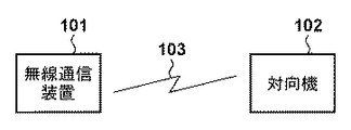
図1は、実施形態1における無線通信装置101と対向機102の接続形態を示す図である。無線通信装置101と対向機102は、無線ネットワーク103を介して、無線チャネルを用いて通信可能なように相互に接続されている。本実施形態では、一例として無線通信装置101と対向機102は、映像データを送受信するための通信機能を備えるものとする。例えば、無線通信装置101と対向機102が備える通信機能は、HTTPやTCP,RTSP,SIP,SOAP等のコネクション型の通信プロトコルを用いた通信機能であり得る。
<
FIG. 1 is a diagram illustrating a connection form between the
無線通信装置101は、一例として、タブレット、スマートフォン、PC、携帯電話、テレビ、カメラ、ビデオカメラ、ヘッドマウントディスプレイ等であるが、後述のハードウェア構成及び機能構成を満たすものであれば、これらに限定されない。一方、対向機102は、一例としてタブレット、スマートフォン、PC、ディスプレイ、携帯電話、テレビ、カメラ、ビデオカメラ、ヘッドマウントディスプレイ、プロジェクター等であるが、これらに限定されない。
The
無線ネットワーク103は、無線通信装置101と対向機102が参加する無線LANであり、例えばIEEE 802.11ac規格に対応した無線ネットワークである。なお、本実施形態では、無線通信装置101は、5GHz帯の周波数帯域のうち、レーダーの電波のモニターが必要なW53とW56帯域を使用する。なお、ユーザによる無線LANチャネルの設定により、無線通信装置101は、レーダーの電波のモニターが不要なW52やW58、あるいは2.4GHz帯の周波数帯域を使用することもできる。
The
図2は、無線通信装置101の機能構成の一例を示す図である。無線LAN制御部201は、所定の無線LANチャネル設定において、他の無線LAN装置との間で無線信号の送受信を行うための制御を行う。映像データ送信制御部202は、対向機102に対して映像データの送信を行うための制御を行う。本実施形態では、映像データの通信方式として、無線LANで画面をミラーリングするWi-Fi Miracastを用いる。Wi-Fi Miracastは、データ転送プロトコルとしてRTP(Real-time Transport Protocol)を用いる。RTPはIETF(The Internet Engineering Task Force)によりRFC3550で標準化された、動画像や音声などのマルチメディアデータをネットワークを介してリアルタイムに送受信するためのプロトコルであり、下位層のトランスポートプロトコルとしてUDPを利用する。
FIG. 2 is a diagram illustrating an example of a functional configuration of the
通信セッション制御部203は、対向機102に対する再生制御や通信セッションの維持などの通信セッションの制御を行う。Wi-Fi Miracastは、再生制御のプロトコルとしてRTSP(Real Time Streaming Protocol)を用いる。RTSPは、RFC2326で標準化されたストリーミングを制御するためのプロトコルであり、下位層のトランスポートプロトコルとしてはTCPを利用する。
The communication
電波干渉検出部204は、無線通信装置101による通信の干渉となる、気象レーダーや軍事レーダー等のレーダーが放出している干渉電波(以下、レーダー電波)をモニターし、検出するための制御を行う。
The radio wave
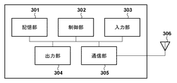
図3は、無線通信装置101のハードウェア構成の一例を示す図である。記憶部301は、ROM(Read Only Memory)やRAM(Random Access Memory)等のメモリにより構成される。記憶部301は、後述する各種動作を行うためのプログラムや、無線通信のための通信パラメータ等の各種情報を記憶する。なお、記憶部301として、ROM、RAM等のメモリの他に、フレキシブルディスク、ハードディスク、光ディスク、光磁気ディスク、CD-ROM、CD-R、磁気テープ、不揮発性のメモリカード、DVDなどの記憶媒体を用いてもよい。また、記憶部301が複数のメモリ等を備えていてもよい。
FIG. 3 is a diagram illustrating an example of a hardware configuration of the
制御部302は、CPU(Central Processing Unit)やMPU(Micro Processing Unit)等のプロセッサにより構成される。制御部302は、記憶部301に記憶されたプログラムを実行することにより無線通信装置101全体を制御する。また、制御部302がマルチコア等の複数のプロセッサを備え、複数のプロセッサにより無線通信装置101全体を制御するようにしてもよい。
The
入力部303は、ユーザからの各種操作の受付を行う。出力部304は、ユーザに対して各種出力を行う。ここで、出力部304による出力とは、画面上への表示や、スピーカーによる音声出力、振動出力等の少なくとも1つを含む。なお、タッチパネルのように入力部303と出力部304の両方を1つのモジュールで実現するようにしてもよい。出力部304は、表示による出力を行う場合、例えばLCD(Liquid Crystal Display)やLED(Light Emitting Diode)により構成される。出力部304は、ユーザが視覚で認知可能な情報を出力し、各種UI(User Interface)の表示制御を行う。
The
通信部305は、無線通信の制御を行う。また、通信部305はアンテナ306を制御して、無線通信のための無線信号の送受信を行う。無線通信装置101は、通信部305を介して、映像データ等のコンテンツを対向機102へ送信する。
The
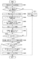
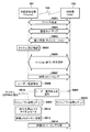
続いて、本実施形態における無線通信装置101による通信セッションの維持制御の詳細について、図4を用いて説明する。図4は、本実施形態における無線通信装置101の通信処理手順の一例を示すフローチャートである。
Next, details of the communication session maintenance control by the
まず、通信セッション制御部203は、無線LAN制御部201に設定されている無線LANチャネルを確認する(ステップS401)。設定された無線LANチャネルには、無線LANチャネルの周波数帯域や、使用可能なチャネル番号等が含まれる。なお、無線LAN制御部201における無線LANチャネルの設定は、ユーザ操作により設定される場合や、無線通信装置101に予め設定される場合や、無線通信装置101により自動で選択・設定される場合等がある。
First, the communication
続いて、通信セッション制御部203は、ステップS401で確認した無線LANチャネルの周波数帯域が、レーダーがいるか否かをモニターするための帯域、すなわちレーダー電波の検出が必要な帯域であるか否かを判断する。(ステップS402)。レーダー電波の検出が必要な帯域は、5GHz帯のW53(無線LANチャネルは52/56/60/64ch)及びW56(無線LANチャネルは100/104/108/112/116/120/124/128/132/136/140ch)の帯域である。またレーダー電波の検出が不必要な帯域は、各国法規制により異なるが、日本においては5GHz帯のW52(無線LANチャネルは36/40/44/48ch)及び2.4GHz帯の無線LANチャネルの帯域である。
Subsequently, the communication
ステップS402の判断の結果、ステップS401で確認した無線LANチャネルの周波数帯域が、レーダー電波の検出が必要な帯域の場合(ステップS402のYes)、処理はステップS403に進む。ステップS403では、電波干渉検出部204は、ステップS401で確認した無線LANチャネルの周波数帯域においてレーダー電波を60秒間モニターし、レーダー電波を検出されない無線LANチャネルを探索する。ここで、電波干渉検出部204が、特定の無線LANチャネルにおいてレーダーモニター中に、レーダー電波を検出したと判定した場合には、モニターする無線LANチャネルを、使用可能なチャネルのうちの、別の無線LANチャネルへ移行し、移行先チャネルにおいて改めてレーダー電波をモニターする。電波干渉検出部204は、この処理を、レーダー電波を検出しなくなるまで繰り返す。無線LAN制御部201は、本ステップにおいて、レーダー未検出の無線LANチャネルを探索し、発見できた無線LANチャネルを使用することを決定する(ステップS404)。しかしながら、無線LAN制御部201は、レーダー未検出の無線LANチャネルを発見できなかった場合は、通信セッションの維持制御の処理を終了する。この場合、所定時間経過後に、再度、無線LAN制御部201は、本ステップによる処理を行うようにしてもよい。
As a result of the determination in step S402, when the frequency band of the wireless LAN channel confirmed in step S401 is a band that requires radar radio wave detection (Yes in step S402), the process proceeds to step S403. In step S403, the radio wave
一方、ステップS401で確認した無線LANチャネルの周波数帯域がレーダー電波の検出が不必要な帯域の場合は(ステップS402のNo)、処理はステップS413に進む。ステップS413では、通信セッション制御部203及び映像データ送信制御部202は、映像ストリーミングを開始するための制御を行う。本実施形態では、通信セッション制御部203が、Wi-Fi Miracastによる所定の処理を行い、これに応じて、映像データ送信制御部202は、対向機102に対して、映像ストリーミングを開始する。また、映像ストリーミング中は、通信セッション制御部203は、所定の間隔でキープアライブ要求を対向機102に対して送信し、通信セッションを維持・管理する。キープアライブ要求は、Wi-Fi Miracastの場合は、RTSP M16(GET_PARAMETER)要求である。なお、ステップS413において、電波干渉検出部204は、レーダー電波の検出等を行わなくてよい。
On the other hand, if the frequency band of the wireless LAN channel confirmed in step S401 is a band that does not require radar radio wave detection (No in step S402), the process proceeds to step S413. In step S413, the communication
ステップS404において、使用する無線LANチャネルが決定された後、通信セッション制御部203は、映像ストリーミングの際に対向機102に対して送信するキープアライブ要求の送信間隔(キープアライブ間隔)Tkを設定する(ステップS405)。本実施形態では、通信セッション制御部203は、無線LANチャネル切り替えに要する時間Tよりも長くなるよう(Tk>Tとなるよう)に、キープアライブ間隔Tkを設定する。なお、キープアライブ間隔は、Wi-Fi Miracastの場合は、RTSP M6(SETUP)応答中のtimeout値で設定可能である。無線LANチャネル切り替えに要する時間Tは、レーダー電波の検出時の移行先チャネル設定により異なる。すなわち、使用可能なチャネルに鑑み、レーダー電波のモニターが必要な帯域へ移行する場合は、時間Tは、無線LAN制御部201でのチャネル切り替え処理に必要な時間に電波干渉検出部204でのモニター時間の60秒を加えた時間となる。また、レーダー電波のモニターが不要な帯域へ移行する場合は、時間Tは、無線LAN制御部201でのチャネル切り替え処理に必要な時間となる。
In step S404, after the wireless LAN channel to be used is determined, the communication
ステップS405において、通信セッション制御部203がキープアライブ間隔Tkを設定した後、通信セッション制御部203及び映像データ送信制御部202は映像ストリーミングを開始する(ステップS406)。尚、本ステップの処理はステップS413での処理と同様であるため説明を省略する。
In step S405, after the communication
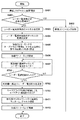
続いて、電波干渉検出部204は、使用している無線LANチャネルにおいて、定期的に、レーダー電波をモニターする(ステップS407)。電波干渉検出部204は、使用している無線LANチャネルにおいてレーダー電波を検出しないと判定した場合(ステップS408のNo)、処理はステップS407へ戻り、電波干渉検出部204は、レーダー電波のモニタ−を継続する。
Subsequently, the radio wave
一方、ステップS407においてレーダー電波を検出したと判定された場合(ステップS408のYes)、通信セッション制御部203は、キープアライブ間隔Tkに関係なく、対向機102に対して即座にキープアライブ要求を送信する(ステップS409)。この後、通信セッション制御部203が、所定時間内に、対向機102からキープアライブ要求に対するキープアライブ応答を受信しない場合には(ステップS410のNo)、タイムアウト処理によりWi-Fi Miracastの映像ストリーミングを終了する。
On the other hand, if it is determined in step S407 that a radar radio wave has been detected (Yes in step S408), the communication
通信セッション制御部203が、対向機102からキープアライブ応答を受信した場合には(ステップS410のYes)、電波干渉検出部204は、モニターする無線LANチャネルを、使用可能なチャネルのうちの別の無線LANチャネルへ移行する。電波干渉検出部204は、移行先の無線LANチャネルがレーダー電波の検出が必要である場合には、該チャネルでレーダー電波をモニターする。モニターしている無線LANチャネルでレーダー電波が検出されなかった場合に、無線LAN制御部201は該モニターしている無線LANチャネルへ、使用チャネルを切り替える(ステップS411)。その後、映像データ送信制御部202は、対向機102への映像ストリーミングを再開する(ステップS412)。モニターしている無線LANチャネルでレーダー電波が検出された場合は、ステップS403の処理と同様な処理が行われる。
When the communication
尚、レーダー電波の検出の判定後(ステップS408のYes)に、無線通信装置101は、現在使用している無線LANチャネルの使用を停止するまでに、対向機102へチャネル変更を通知することができる。この場合、無線通信装置101は、ビーコンやプローブ要求、Channel Switch Announcementフレーム等の無線管理フレームに、移行先のチャネル情報(Channel Switch Announcement element)を付与する。また、この場合、無線通信装置101は、出力部304により「DFS中」または「レーダーによる干渉電波検出により無線LANチャネルを切り替え中」等と表示出力することで、ユーザへその旨を通知することが可能である。また、無線通信装置101がレーダーによる干渉電波を検出してから無線LANチャネル切り替えが完了するまでの間、映像データ送信制御部202はステップS406で開始した映像データの送信を停止しても良い。
After the determination of the detection of the radar radio wave (Yes in step S408), the
図5は、移行先のチャネル情報として使用されるChannel Switch Announcement element formatの構成を示す概略図である。本情報により、新チャネルへ移行すること、また新チャネルのチャネル番号の通知が可能となる。New Channel Numberフィールドには、移行先のチャネル番号が設定される。 FIG. 5 is a schematic diagram showing a configuration of a Channel Switch Announcement element format used as channel information of the transfer destination. With this information, it is possible to shift to a new channel and to notify the channel number of the new channel. The channel number of the transfer destination is set in the New Channel Number field.
次に、図6を参照して、本実施形態における無線通信装置101と対向機102との接続シーケンスを説明する。図6は、無線通信装置101がレーダー電波を検出する場合の対向機102との接続シーケンスを説明する。尚、ここでは、無線通信装置101が映像ストリーミングを送信するためのWi-Fi Miracast Source機能を備え、対向機102が映像ストリーミングを受信するためのSink機能を備えるものとする。さらに、無線通信装置101は、GO(Group Owner)となり、レーダー電波を検出する機能を備えるものとして説明を行う。
Next, a connection sequence between the
まず、無線通信装置101と対向機102間において、デバイス発見(S601)、接続セットアップ(S602)、能力交換・ネゴシエーション(S603)が行われる。その後、無線通信装置101は、ステップS401で説明したように、無線LANチャネルの設定の確認を行う(S604)。尚、デバイス発見(S601)と接続セットアップ(S602)では、Wi-Fi Miracast仕様に基づき所定の無線管理フレームが利用される。また、能力交換・ネゴシエーション(S603)では、前述したRTSPの所定のメッセージが無線通信装置101と対向機102との間で交換される。S601〜S603の処理の詳細な説明はここでは省略する。
First, device discovery (S601), connection setup (S602), and capability exchange / negotiation (S603) are performed between the
続いて、セッション確立・再生開始(S605)において、キープアライブ間隔の設定が行わる。図6の例では、RTSP M6(SETUP)応答中のtimeout値により、65秒に設定される(S606)。65秒は、移行先の無線LANチャネルでのレーダーモニター時間の60秒と、チャネル切り替えに要する時間の和よりも長い時間として設定されている。 Subsequently, in the session establishment / reproduction start (S605), a keep alive interval is set. In the example of FIG. 6, 65 seconds is set by the timeout value in the RTSP M6 (SETUP) response (S606). 65 seconds is set as a time longer than the sum of 60 seconds of the radar monitoring time in the destination wireless LAN channel and the time required for channel switching.
次に、無線通信装置101から映像ストリーミングが開始される(S607)。無線通信装置101がレーダー電波を検出したと判定すると(S608)、即座にキープアライブ要求/応答(RTSP M16(GET_PARAMETER))の送受信が行われる(S609、S611)。また、無線通信装置101は、レーダー電波検出時には、上述したように、チャネル切り替え中であることをユーザへ通知する(S610)。続いて、移行先の無線LANチャネルにおけるレーダー電波のモニター(S612)が60秒行われ、無線LANチャネルの切り替え(S613)処理が完了後、映像ストリーミングが再開される(S614)。
Next, video streaming is started from the wireless communication apparatus 101 (S607). When it is determined that the
なお、S612の段階において、レーダー電波の検出が判定された場合、無線通信装置101は、キープアライブ間隔を、S605において設定した間隔より長い間隔に設定し、設定した間隔を対向機102に通知するようにしてもよい。
If it is determined in step S612 that the radar radio wave is detected, the
以上のように、本実施形態における無線通信装置は、無線LANチャネル切り替えに要する時間よりも長くなるように、キープアライブ間隔を設定する。また、該無線通信装置は、DFS機能により通信が停止する場合に即座にキープアライブ要求を送信する。これにより、無線LANチャネル切り替え中の通信セッションのタイムアウトを防止し、無線LANチャネル切り替え後も通信セッションを維持できるようになる。また、セッション切断後の再接続のためのユーザ操作や送受信装置間のメッセージ交換が必要なくなり、通信の継続が可能となる。 As described above, the wireless communication apparatus according to the present embodiment sets the keep alive interval so as to be longer than the time required for wireless LAN channel switching. Further, the wireless communication apparatus immediately transmits a keep alive request when communication is stopped by the DFS function. As a result, a timeout of the communication session during the wireless LAN channel switching can be prevented, and the communication session can be maintained even after the wireless LAN channel switching. In addition, user operation for reconnection after session disconnection and message exchange between transmission / reception devices are not required, and communication can be continued.
<実施形態2>
上述の実施形態1における無線通信装置は、DFSによる無線LANチャネル切り替えに要する時間を考慮して通信セッションのキープアライブ間隔を設定する構成とした。これに対して本実施形態では、無線通信装置は、通信セッションのキープアライブ間隔は変更せず、レーダー電波検知時にキープアライブ時間が経過してもタイムアウト処理(通信セッションを停止する処理)をスキップする例を説明する。
<
The wireless communication apparatus according to the first embodiment is configured to set the communication session keep-alive interval in consideration of the time required for wireless LAN channel switching by DFS. On the other hand, in this embodiment, the wireless communication device does not change the keep alive interval of the communication session, and skips the timeout process (process for stopping the communication session) even if the keep alive time elapses when the radar radio wave is detected. An example will be described.
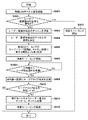
図7は、本実施形態における無線通信装置101の通信処理手順の一例を示すフローチャートである。実施形態1において説明した図4と異なるステップS701〜ステップS703の処理を説明し、他のステップの処理の説明は省略する。
FIG. 7 is a flowchart illustrating an example of a communication processing procedure of the
ステップS701において電波干渉検出部204がレーダー電波を検出したと判定した場合には(S701のYes)、無線LAN制御部201は、対向機102へ即座にレーダー電波を検出したことを通知する(ステップS702)。ここでの通知方法としては、例えば、Measurement Reportフレーム等の無線管理フレームにレーダー電波検出情報を付加すること等が可能である
If it is determined in step S701 that the radio wave
図8は、レーダー電波検出情報として使用されるMeasurement Report element formatの構成を示す概略図である。レーダー電波が検出された場合には、Mapフィールド中のRadarビットが1に設定される。なお、通知方法はMeasurement Reportフレームを用いる方法に限らず、独自仕様のデータ通信による通知方法であっても良い。 FIG. 8 is a schematic diagram showing a configuration of a measurement report element format used as radar radio wave detection information. When radar radio waves are detected, the Radar bit in the Map field is set to 1. Note that the notification method is not limited to the method using the Measurement Report frame, and may be a notification method using proprietary data communication.
続いて、通信セッション制御部203は、レーダー電波検出後にキープアライブ要求を送信する時間(キープアライブ時間)が経過しても、タイムアウト処理をスキップする(ステップS703)。スキップする期間は、無線LANチャネル切り替え(ステップS411)が完了するまでの間であり、無線LANチャネル切り替え後は本来のキープアライブ間隔でタイムアウト処理を再開する。
Subsequently, the communication
次に、図9を参照して、本実施形態における無線通信装置101と対向機102との接続シーケンスを説明する。図9は、無線通信装置101がレーダー電波を検出する場合の対向機102との接続シーケンスを説明する。同図において、図6と同じ部分には同じ番号を付与し、その詳細な説明は省略する。
Next, with reference to FIG. 9, a connection sequence between the
図7を用いて前述した通り、本実施形態における無線通信装置は、通信セッションのキープアライブ間隔を変更しない。そのため、図6のS606におけるキープアライブ時間の変更(RTSP M6応答でのtimeout=65指定)は行われず、所定のタイムアウト時間がキープアライブ間隔として使用される。なおWi-Fi Miracastの場合、RTSP M6応答でtimeout値を指定しなければその時間は60秒と定められている。 As described above with reference to FIG. 7, the wireless communication apparatus according to the present embodiment does not change the keep-alive interval of the communication session. Therefore, the keep alive time is not changed in S606 in FIG. 6 (timeout = 65 is specified in the RTSP M6 response), and a predetermined timeout time is used as the keep alive interval. In the case of Wi-Fi Miracast, if no timeout value is specified in the RTSP M6 response, the time is set to 60 seconds.
また、無線通信装置101はレーダー電波を検出したと判定すると(S608)、ステップS707で説明したように、対向機102へ即座にレーダー電波を検出したことを通知する(S901)。また、無線通信装置101と対向機102は共に、レーダー電波検出後から無線LANチャネル切り替えが完了するまでの間は、キープアライブ時間が経過してもタイムアウト処理をスキップする(S902、S903)。
If the
以上のように、本実施形態における無線通信装置は、通信セッションのキープアライブ間隔を変更せず、レーダー電波検知後にキープアライブ時間が経過しても、タイムアウト処理をスキップする。これにより、無線LANチャネル切り替え中の通信セッションのタイムアウトを防止し、無線LANチャネル切り替え後も通信セッションを維持できるようになる。また、セッション切断後の再接続のためのユーザ操作や送受信装置間のメッセージ交換が必要なくなり、通信の継続が可能となる。 As described above, the wireless communication apparatus in the present embodiment does not change the keep alive interval of the communication session, and skips the timeout process even if the keep alive time elapses after the radar radio wave is detected. As a result, a timeout of the communication session during the wireless LAN channel switching can be prevented, and the communication session can be maintained even after the wireless LAN channel switching. In addition, user operation for reconnection after session disconnection and message exchange between transmission / reception devices are not required, and communication can be continued.
<実施形態3>
上述の実施形態1及び実施形態2では、無線通信装置101がレーダー電波を検知する構成とした。これに対して本実施形態では、対向機102がレーダー電波を検知する例を説明する。
<
In the first embodiment and the second embodiment described above, the
図10は、本実施形態における無線通信装置101の通信処理手順の一例を示すフローチャートである。実施形態1において説明した図4と異なるステップS1001の処理を説明し、他のステップの処理の説明は省略する。
FIG. 10 is a flowchart illustrating an example of a communication processing procedure of the
ステップS406において映像ストリーミングが開始された後、無線LAN制御部201は、対向機102からレーダー電波検出通知を受信したか否かを判断する(ステップS1001)。レーダー電波検出通知は、例えば実施形態2で説明したMeasurement Reportフレーム等の無線管理フレームである。無線LAN制御部201が対向機からレーダー電波検出通知を受信した場合(S1001のYes)、通信セッション制御部203は対向機102へ即座にキープアライブ要求を送信し、対向機102から応答を受信する。
After video streaming is started in step S406, the wireless
図11は、本実施形態における対向機102の通信処理手順の一例を示すフローチャートである。対向機102は、無線通信装置101と同様のハードウェア構成(図2)及び機能構成(図3)を有するものとする。ここでは、実施形態1において説明した図4と異なるステップS1101〜ステップS1103の処理を説明し、他のステップの処理の説明は省略する。
FIG. 11 is a flowchart illustrating an example of a communication processing procedure of the
ステップS408において電波干渉検出部204によりレーダー電波が検出された後(ステップS408のYes)、無線LAN制御部201は、無線通信装置101へ即座にレーダー電波検出を通知する(ステップS1101)。ここでの通知方法は、実施形態2で説明したステップS702と同様の方法を用いることが可能である。続いて、通信セッション制御部203は、無線通信装置101からキープアライブ要求を受信した場合に(ステップS1102のYes)、無線通信装置101へ応答を送信する(ステップS1103)。このように、対向機102側でレーダー電波を検出した際も、レーダー電波検出後に即座に無線通信装置101と対向機102がキープアライブ処理を実施することで、無線LANチャネル切り替え中にも通信セッションを維持することが可能になる。
After the radar radio wave is detected by the radio wave
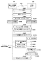
次に、図12を参照して、本実施形態における無線通信装置101と対向機102との接続シーケンスを説明する。図12は、対向機102がレーダー電波を検出する場合の接続シーケンスを説明する。同図において、図6と同じ部分には同じ番号を付与し、その詳細な説明は省略する。尚、ここでは対向機102がGO(Group Owner)となり、レーダー電波を検出する機能を備えるものとして説明を行う。
Next, with reference to FIG. 12, a connection sequence between the
まず、無線通信装置101と対向機102間において、デバイス発見(S601)、接続セットアップ(S602)、能力交換・ネゴシエーション(S603)が行われる。その後、無線通信装置101は、ステップS401で説明したように、無線LANチャネルの設定の確認を行う(S604)。また、対向機102は、ステップS401で説明した手順と同様の手順により、無線LANチャネル設定の確認を行う(S1201)。続いて、セッション確立・再生開始(S605)において、キープアライブ間隔の設定が行わる。図6の例では、RTSP M6(SETUP)応答中のtimeout値により、65秒に設定される(S606)。
First, device discovery (S601), connection setup (S602), and capability exchange / negotiation (S603) are performed between the
次に、無線通信装置101から映像ストリーミングが開始される(S607)。対向機102がレーダー電波を検出すると(S1202)、ステップS1101で説明したように、無線通信装置101へ即座にレーダー電波を検出したことを通知する(S1203)。これにより、無線通信装置101は、レーダー電波の検出を判定する。続いて、キープアライブメッセージ(RTSP M16(GET_PARAMETER))の送受信が行われた後(S609、S611)、対向機102において移行先の無線LANチャネルにおけるレーダー電波のモニター(S1204)が60秒行われる、その後、無線LANチャネルの切り替え(S1205)処理が完了後、映像ストリーミングが再開される(S614)。
Next, video streaming is started from the wireless communication apparatus 101 (S607). When the
以上のように、本実施形態では、対向機102がレーダー電波を検出する場合にも、対向機102は無線通信装置101へレーダー電波検出を通知し即座にキープアライブ処理を行う。これにより、無線LANチャネル切り替え中の通信セッションのタイムアウトを防止し、無線LANチャネル切り替え後も通信セッションを維持できるようになる。また、セッション切断後の再接続のためのユーザ操作や送受信装置間のメッセージ交換が必要なくなり、通信の継続が可能となる。
As described above, in this embodiment, even when the
このように、以上の実施形態によれば、無線LANによる通信中にDFS機能により通信が停止した場合でも、通信セッションを維持できるようになる。そのため、再接続のためのユーザ操作や送受信装置間のメッセージ交換無しで、通信が継続され、ユーザの利便性が向上する。 As described above, according to the above embodiment, a communication session can be maintained even when communication is stopped by the DFS function during communication by wireless LAN. Therefore, communication is continued without user operation for reconnection or message exchange between the transmission and reception devices, and user convenience is improved.
<その他の実施形態>
前述の実施形態では、データ転送プロトコルとしてRTPを用いたが、RTPに限らずHTTPやHTTPS、TCPなどOSI参照モデルの同一レイヤーの他のプロトコルまたは別レイヤーの他のプロトコルを用いる事が可能である。
<Other embodiments>
In the above-described embodiment, RTP is used as the data transfer protocol. However, the protocol is not limited to RTP, but other protocols in the same layer of the OSI reference model such as HTTP, HTTPS, TCP, or other protocols in another layer can be used. .
また、前述の実施形態では、再生制御プロトコルとしてRTSPを使用する例について説明したが、RTSP以外にもSIP(Session Initiation Protocol)やSOAP(Simple Object Access Protocol)等の再生制御プロトコルを利用することも可能である。 In the above-described embodiment, an example in which RTSP is used as a playback control protocol has been described. However, other than RTSP, a playback control protocol such as SIP (Session Initiation Protocol) or SOAP (Simple Object Access Protocol) may be used. Is possible.
以上、実施形態例を詳述したが、本発明は例えば、システム、装置、方法、プログラム若しくは記録媒体(記憶媒体)等としての実施態様をとることが可能である。具体的には、複数の機器(例えば、ホストコンピュータ、インタフェース機器、撮像装置、webアプリケーション等)から構成されるシステムに適用しても良いし、また、一つの機器からなる装置に適用しても良い。 Although the embodiment has been described in detail above, the present invention can take an embodiment as a system, apparatus, method, program, recording medium (storage medium), or the like. Specifically, the present invention may be applied to a system composed of a plurality of devices (for example, a host computer, an interface device, an imaging device, a web application, etc.), or may be applied to a device composed of a single device. good.
本発明は、上述の実施形態の1以上の機能を実現するプログラムを、ネットワーク又は記憶媒体を介してシステム又は装置に供給し、そのシステム又は装置のコンピュータにおける1つ以上のプロセッサーがプログラムを読出し実行する処理でも実現可能である。また、1以上の機能を実現する回路(例えば、ASIC)によっても実現可能である。 The present invention supplies a program that realizes one or more functions of the above-described embodiments to a system or apparatus via a network or a storage medium, and one or more processors in a computer of the system or apparatus read and execute the program This process can be realized. It can also be realized by a circuit (for example, ASIC) that realizes one or more functions.
101 無線通信装置、 102 対向機、 103 ネットワーク、 201 無線LAN制御部、 202 映像データ送信制御部、 203 通信セッション制御部、 204 電波干渉検出部
DESCRIPTION OF
Claims (13)
所定の無線チャネルにおいて他の通信装置との通信セッションを確立する確立手段と、
前記所定の無線チャネルにおける干渉電波の検出を判定する判定手段と、
前記確立手段により前記通信セッションが確立された場合、前記通信セッションを維持するための信号を所定のタイミングが到来する毎に送信する送信手段と、を有し、
前記送信手段は、前記判定手段により前記所定の無線チャネルにおいて干渉電波の検出が判定されたことに応じて、次の前記所定のタイミングが到来する前に、前記信号を送信することを特徴とする通信装置。 A communication device,
Establishing means for establishing a communication session with another communication device in a predetermined wireless channel;
Determining means for determining detection of interference radio waves in the predetermined radio channel;
A transmission means for transmitting a signal for maintaining the communication session each time a predetermined timing arrives when the communication session is established by the establishment means;
The transmission means transmits the signal before the next predetermined timing arrives in response to the determination of the detection of the interference radio wave in the predetermined radio channel by the determination means. Communication device.
所定の無線チャネルにおいて他の通信装置との通信セッションを確立する確立手段と、
前記所定の無線チャネルにおける干渉電波の検出を判定する判定手段と、
前記確立手段により前記通信セッションが確立された場合、前記他の通信装置から繰り返し送信される信号であって、前記信号を受信してから所定のタイミングが到来するまでの間、前記通信装置に前記通信セッションを維持させるための前記信号を受信する受信手段と、
前記確立手段により前記通信セッションが確立され、かつ、前記判定手段により前記所定の無線チャネルにおいて干渉電波の検出が判定された場合、前記受信手段により次の前記信号を受信することなく前記所定のタイミングが到来した場合であっても、前記通信セッションを維持する維持手段と、
を有することを特徴とする通信装置。 A communication device,
Establishing means for establishing a communication session with another communication device in a predetermined wireless channel;
Determining means for determining detection of interference radio waves in the predetermined radio channel;
When the communication session is established by the establishing unit, the signal is repeatedly transmitted from the other communication device, and the communication device receives the signal until the predetermined timing arrives. Receiving means for receiving the signal for maintaining a communication session ;
When the establishment means establishes the communication session and the determination means determines that the interference radio wave is detected in the predetermined radio channel, the reception means does not receive the next signal without receiving the next signal. even if but arriving, and maintaining means for maintaining the communication session,
A communication apparatus comprising:
前記維持手段は、前記切替手段による無線チャネルの切替が完了するまで前記切断手段による切断を行わないことで、前記他の通信装置との前記通信セッションを維持することを特徴とする請求項3に記載の通信装置。 The maintenance unit maintains the communication session with the other communication device by not disconnecting by the disconnecting unit until the switching of the wireless channel by the switching unit is completed. The communication device described.
前記判定手段は、前記検出手段による干渉電波の検出に基づいて判定を行うことを特徴とする請求項1から6のいずれか1項に記載の通信装置。 Further comprising detecting means for detecting interference radio waves in the predetermined radio channel;
It said determination means, the communication device according to any one of 6 claim 1, characterized in that a determination based on detection of interference waves by the detection means.
前記判定手段は、前記受信手段により受信した前記通知に基づいて判定を行うことを特徴とする請求項1から8のいずれか1項に記載の通信装置。 Receiving means for receiving from the other communication device a notification indicating that an interference radio wave has been detected in the predetermined radio channel;
Said determination means, the communication device according to any one of claims 1 8, characterized in that a determination based on the received notification by the receiving means.
所定の無線チャネルにおいて通信セッションを確立する確立工程と、
前記所定の無線チャネルにおける干渉電波の検出を判定する判定工程と、
前記通信セッションが確立された場合、前記通信セッションを維持するための信号を所定のタイミングが到来する毎に送信する第1の送信工程と、
前記所定の無線チャネルにおいて干渉電波の検出が判定されたことに応じて、次の前記所定のタイミングが到来する前に、前記信号を送信する第2の送信工程と、
を有することを特徴とする通信方法。 A communication method,
Establishing a communication session on a predetermined radio channel;
A determination step of determining detection of interference radio waves in the predetermined radio channel;
When the communication session is established, a first transmission step of transmitting a signal for maintaining the communication session every time a predetermined timing arrives ;
A second transmission step of transmitting the signal before the next predetermined timing arrives in response to determination of detection of interference radio waves in the predetermined radio channel;
A communication method characterized by comprising:
所定の無線チャネルにおいて他の通信装置との通信セッションを確立する確立工程と、
前記所定の無線チャネルにおける干渉電波の検出を判定する判定工程と、
前記通信セッションが確立された場合、前記他の通信装置から繰り返し送信される信号であって、前記信号を受信してから所定のタイミングが到来するまでの間、前記通信装置に前記通信セッションを維持させるための前記信号を受信する受信工程と、
前記通信セッションが確立され、かつ、前記所定の無線チャネルにおいて干渉電波の検出が判定された場合、次の前記信号を受信することなく前記所定のタイミングが到来した場合であっても、前記通信セッションを維持する維持工程と、
を有することを特徴とする通信方法。 A communication method,
An establishing step of establishing a communication session with another communication device in a predetermined wireless channel;
A determination step of determining detection of interference radio waves in the predetermined radio channel;
When the communication session is established, the signal is repeatedly transmitted from the other communication device, and the communication session is maintained in the communication device until a predetermined timing comes after receiving the signal. a reception step of receiving the signal for,
When the communication session is established and the detection of interference radio waves in the predetermined radio channel is determined, even if the predetermined timing arrives without receiving the next signal , the communication session Maintenance process to maintain,
A communication method characterized by comprising:
Priority Applications (2)
| Application Number | Priority Date | Filing Date | Title |
|---|---|---|---|
| JP2015199720A JP6573391B2 (en) | 2015-10-07 | 2015-10-07 | Wireless communication apparatus, wireless communication method, and program |
| US15/286,939 US10244576B2 (en) | 2015-10-07 | 2016-10-06 | Communication apparatus, communication method, and non-transitory computer-readable storage medium |
Applications Claiming Priority (1)
| Application Number | Priority Date | Filing Date | Title |
|---|---|---|---|
| JP2015199720A JP6573391B2 (en) | 2015-10-07 | 2015-10-07 | Wireless communication apparatus, wireless communication method, and program |
Publications (3)
| Publication Number | Publication Date |
|---|---|
| JP2017073675A JP2017073675A (en) | 2017-04-13 |
| JP2017073675A5 JP2017073675A5 (en) | 2018-11-15 |
| JP6573391B2 true JP6573391B2 (en) | 2019-09-11 |
Family
ID=58499189
Family Applications (1)
| Application Number | Title | Priority Date | Filing Date |
|---|---|---|---|
| JP2015199720A Active JP6573391B2 (en) | 2015-10-07 | 2015-10-07 | Wireless communication apparatus, wireless communication method, and program |
Country Status (2)
| Country | Link |
|---|---|
| US (1) | US10244576B2 (en) |
| JP (1) | JP6573391B2 (en) |
Families Citing this family (4)
| Publication number | Priority date | Publication date | Assignee | Title |
|---|---|---|---|---|
| JP7135584B2 (en) * | 2018-08-22 | 2022-09-13 | ブラザー工業株式会社 | Communication device and computer program for communication device |
| US11930372B2 (en) | 2018-11-07 | 2024-03-12 | Sony Group Corporation | Communication control apparatus, communication apparatus, and communication control method |
| JP6954670B2 (en) * | 2019-11-13 | 2021-10-27 | Necプラットフォームズ株式会社 | Base station equipment, control method and control program |
| JP7468106B2 (en) * | 2020-04-16 | 2024-04-16 | セイコーエプソン株式会社 | Wireless communication device and wireless communication method |
Family Cites Families (27)
| Publication number | Priority date | Publication date | Assignee | Title |
|---|---|---|---|---|
| FR2739511A1 (en) * | 1995-10-02 | 1997-04-04 | Canon Kk | METHODS, APPARATUSES AND SYSTEMS FOR SHARING TRANSMISSION MEDIUM, TRANSMISSION METHOD, COMMUNICATION APPARATUSES AND COMMUNICATION SYSTEMS USING THEM |
| JP2001285301A (en) * | 2000-03-30 | 2001-10-12 | Japan Radio Co Ltd | Radio lan apparatus |
| JP4267805B2 (en) * | 2000-08-02 | 2009-05-27 | 富士通株式会社 | CDMA receiver and path detection control method |
| JP3968514B2 (en) * | 2002-07-05 | 2007-08-29 | ソニー株式会社 | Wireless communication system, wireless communication apparatus, wireless communication method, and computer program |
| JP4117781B2 (en) * | 2002-08-30 | 2008-07-16 | セイコーインスツル株式会社 | Data transmission system and body-mounted communication device |
| JP3846715B2 (en) * | 2002-09-30 | 2006-11-15 | ソニー株式会社 | Wireless communication system |
| JP4489498B2 (en) * | 2004-05-24 | 2010-06-23 | 三菱電機株式会社 | Wireless base station |
| TWI296468B (en) * | 2005-11-11 | 2008-05-01 | Inst Information Industry | Wireless system, method for reconnection, and computer readable medium thereof |
| KR100979400B1 (en) * | 2006-01-11 | 2010-09-01 | 퀄컴 인코포레이티드 | Communication methods and apparatus used in the absence or presence of beacon signals |
| US9538388B2 (en) * | 2006-05-12 | 2017-01-03 | Shared Spectrum Company | Method and system for dynamic spectrum access |
| US8326313B2 (en) * | 2006-05-12 | 2012-12-04 | Shared Spectrum Company | Method and system for dynamic spectrum access using detection periods |
| JP2008072492A (en) * | 2006-09-14 | 2008-03-27 | Oki Electric Ind Co Ltd | Hall management system, short range radio equipment, and communication timing control system |
| JP4582720B2 (en) * | 2007-04-17 | 2010-11-17 | 富士通テン株式会社 | Communication processing device |
| US8363578B1 (en) * | 2007-04-23 | 2013-01-29 | Marvell International Ltd. | Bandwidth selection method and apparatus |
| JP2008278148A (en) * | 2007-04-27 | 2008-11-13 | Nec Corp | Communication terminal, communication route control method and program |
| JP2010141625A (en) | 2008-12-12 | 2010-06-24 | Panasonic Corp | Radio transmitting system, radio base station apparatus, and communication channel selecting method |
| JP4886814B2 (en) | 2009-05-29 | 2012-02-29 | 株式会社バッファロー | Wireless communication apparatus, wireless communication system, and wireless communication method |
| US8355389B2 (en) * | 2010-03-12 | 2013-01-15 | Nokia Corporation | Simultaneous transmissions during a transmission opportunity |
| KR20140138132A (en) * | 2012-03-02 | 2014-12-03 | 엘지전자 주식회사 | Device and method for active scanning |
| US9155110B2 (en) * | 2013-03-27 | 2015-10-06 | Magnolia Broadband Inc. | System and method for co-located and co-channel Wi-Fi access points |
| JP6167583B2 (en) | 2013-03-19 | 2017-07-26 | 株式会社バッファロー | Wireless communication apparatus and wireless communication channel selection method |
| US9497781B2 (en) * | 2013-08-13 | 2016-11-15 | Magnolia Broadband Inc. | System and method for co-located and co-channel Wi-Fi access points |
| EP3123804B1 (en) * | 2014-03-28 | 2019-12-04 | Intel IP Corporation | Mechanisms of virtual clear channel assessment for wi-fi devices |
| US9340298B1 (en) * | 2015-01-12 | 2016-05-17 | FliteLogix, LLC | Aircraft refueling safety system |
| US20160262173A1 (en) * | 2015-03-03 | 2016-09-08 | Samsung Electronics Co., Ltd | Methods for uplink channel access in wireless local area networks |
| US10231179B2 (en) * | 2015-08-06 | 2019-03-12 | Qualcomm Incorporated | Access point standby power optimization across an arbitrary number of associated clients |
| US10368366B2 (en) * | 2015-09-16 | 2019-07-30 | Nokia Solutions And Networks Oy | Method and apparatus for implementing uplink scheduling in an unlicensed spectrum |
-
2015
- 2015-10-07 JP JP2015199720A patent/JP6573391B2/en active Active
-
2016
- 2016-10-06 US US15/286,939 patent/US10244576B2/en active Active
Also Published As
| Publication number | Publication date |
|---|---|
| US20170105242A1 (en) | 2017-04-13 |
| US10244576B2 (en) | 2019-03-26 |
| JP2017073675A (en) | 2017-04-13 |
Similar Documents
| Publication | Publication Date | Title |
|---|---|---|
| JP6573391B2 (en) | Wireless communication apparatus, wireless communication method, and program | |
| RU2656230C2 (en) | Information processing device and information processing method | |
| KR102400856B1 (en) | Communication apparatus, control method, and program | |
| RU2696598C2 (en) | Information processing device, information processing method and program | |
| US20180084373A1 (en) | Communication apparatus and control method therefor | |
| US20180341453A1 (en) | Communication apparatus, communication method, and storage medium | |
| US20190200281A1 (en) | Communication apparatus, control method, and storage medium | |
| US10075517B2 (en) | Display apparatus and control method thereof | |
| JP2020065203A (en) | Communication device, method of controlling the same, and program | |
| US10734031B2 (en) | Communication apparatus, communication system, communication method, and storage medium | |
| US11457267B2 (en) | Communication apparatus, communication method, and storage medium | |
| JP6701021B2 (en) | Communication device, communication method, and program | |
| US10129892B2 (en) | Techniques to manage reverse channel audio sessions | |
| US20150003403A1 (en) | Systems and methods for reduced latency and improved beacon reception in devices capable of providing multiple wireless interfaces via a single radio | |
| JP2019159505A (en) | Communication apparatus, communication method and program | |
| JP6783524B2 (en) | Communication equipment, control methods, and programs | |
| JP2019215762A (en) | Communication device, control method, and program | |
| EP3873137A1 (en) | Network parameter configuration method and apparatus, and computer-readable storage medium | |
| US20180317272A1 (en) | Communication apparatus, control method, and recording medium | |
| KR20190064454A (en) | Communication apparatus, control method, program, and storage medium | |
| JP2017050781A (en) | Communication device, control method, and program | |
| US20240073881A1 (en) | Method and apparatus for indicating number of pucch transmissions, and repeat transmission method and apparatus | |
| WO2023050049A1 (en) | Information reporting method and apparatus, beam switching method and apparatus, and storage medium | |
| JP7146473B2 (en) | Communication device, communication method and program | |
| JP2019169870A (en) | Communication device, control method, and program |
Legal Events
| Date | Code | Title | Description |
|---|---|---|---|
| A521 | Request for written amendment filed |
Free format text: JAPANESE INTERMEDIATE CODE: A523 Effective date: 20181003 |
|
| A621 | Written request for application examination |
Free format text: JAPANESE INTERMEDIATE CODE: A621 Effective date: 20181003 |
|
| A977 | Report on retrieval |
Free format text: JAPANESE INTERMEDIATE CODE: A971007 Effective date: 20190628 |
|
| TRDD | Decision of grant or rejection written | ||
| A01 | Written decision to grant a patent or to grant a registration (utility model) |
Free format text: JAPANESE INTERMEDIATE CODE: A01 Effective date: 20190716 |
|
| A61 | First payment of annual fees (during grant procedure) |
Free format text: JAPANESE INTERMEDIATE CODE: A61 Effective date: 20190809 |
|
| R151 | Written notification of patent or utility model registration |
Ref document number: 6573391 Country of ref document: JP Free format text: JAPANESE INTERMEDIATE CODE: R151 |