JP3967882B2 - Ultrasonic diagnostic equipment - Google Patents
Ultrasonic diagnostic equipment Download PDFInfo
- Publication number
- JP3967882B2 JP3967882B2 JP2001031965A JP2001031965A JP3967882B2 JP 3967882 B2 JP3967882 B2 JP 3967882B2 JP 2001031965 A JP2001031965 A JP 2001031965A JP 2001031965 A JP2001031965 A JP 2001031965A JP 3967882 B2 JP3967882 B2 JP 3967882B2
- Authority
- JP
- Japan
- Prior art keywords
- transmission
- reception
- code
- ultrasonic
- signal processing
- Prior art date
- Legal status (The legal status is an assumption and is not a legal conclusion. Google has not performed a legal analysis and makes no representation as to the accuracy of the status listed.)
- Expired - Fee Related
Links
Images


Classifications
-
- G—PHYSICS
- G01—MEASURING; TESTING
- G01S—RADIO DIRECTION-FINDING; RADIO NAVIGATION; DETERMINING DISTANCE OR VELOCITY BY USE OF RADIO WAVES; LOCATING OR PRESENCE-DETECTING BY USE OF THE REFLECTION OR RERADIATION OF RADIO WAVES; ANALOGOUS ARRANGEMENTS USING OTHER WAVES
- G01S15/00—Systems using the reflection or reradiation of acoustic waves, e.g. sonar systems
- G01S15/88—Sonar systems specially adapted for specific applications
- G01S15/89—Sonar systems specially adapted for specific applications for mapping or imaging
- G01S15/8906—Short-range imaging systems; Acoustic microscope systems using pulse-echo techniques
- G01S15/8959—Short-range imaging systems; Acoustic microscope systems using pulse-echo techniques using coded signals for correlation purposes
-
- G—PHYSICS
- G01—MEASURING; TESTING
- G01S—RADIO DIRECTION-FINDING; RADIO NAVIGATION; DETERMINING DISTANCE OR VELOCITY BY USE OF RADIO WAVES; LOCATING OR PRESENCE-DETECTING BY USE OF THE REFLECTION OR RERADIATION OF RADIO WAVES; ANALOGOUS ARRANGEMENTS USING OTHER WAVES
- G01S7/00—Details of systems according to groups G01S13/00, G01S15/00, G01S17/00
- G01S7/52—Details of systems according to groups G01S13/00, G01S15/00, G01S17/00 of systems according to group G01S15/00
- G01S7/52017—Details of systems according to groups G01S13/00, G01S15/00, G01S17/00 of systems according to group G01S15/00 particularly adapted to short-range imaging
- G01S7/52085—Details related to the ultrasound signal acquisition, e.g. scan sequences
- G01S7/5209—Details related to the ultrasound signal acquisition, e.g. scan sequences using multibeam transmission
-
- G—PHYSICS
- G01—MEASURING; TESTING
- G01S—RADIO DIRECTION-FINDING; RADIO NAVIGATION; DETERMINING DISTANCE OR VELOCITY BY USE OF RADIO WAVES; LOCATING OR PRESENCE-DETECTING BY USE OF THE REFLECTION OR RERADIATION OF RADIO WAVES; ANALOGOUS ARRANGEMENTS USING OTHER WAVES
- G01S7/00—Details of systems according to groups G01S13/00, G01S15/00, G01S17/00
- G01S7/52—Details of systems according to groups G01S13/00, G01S15/00, G01S17/00 of systems according to group G01S15/00
- G01S7/52017—Details of systems according to groups G01S13/00, G01S15/00, G01S17/00 of systems according to group G01S15/00 particularly adapted to short-range imaging
- G01S7/52085—Details related to the ultrasound signal acquisition, e.g. scan sequences
- G01S7/52095—Details related to the ultrasound signal acquisition, e.g. scan sequences using multiline receive beamforming
-
- A—HUMAN NECESSITIES
- A61—MEDICAL OR VETERINARY SCIENCE; HYGIENE
- A61B—DIAGNOSIS; SURGERY; IDENTIFICATION
- A61B8/00—Diagnosis using ultrasonic, sonic or infrasonic waves
Description
【0001】
【発明の属する技術分野】
本発明は、超音波を用いて生体を撮像する超音波診断装置に関する。
【0002】
【従来の技術】
超音波診断装置は、超音波ビームを対象物に送受信して対象物の画像を得る装置であるが、信号歪み低減、S/N向上の観点から、信号処理のディジタル化、超音波ビームの符号化が検討されてきた。例えば、文献、IEEE TRANSACTION ON ULTRASONICS、 FERROELECTRICS、 AND FREQUENCY CONTROL誌, 39巻, No.3,341頁から351頁(1992年)には、時間軸方向に伸ばした符号化した超音波信号を生体内に送波し、生体内の反射体から反射された信号をフィルタリング処理により時間軸方向に圧縮する超音波ビームの送受信方法が開示されている。
【0003】
また、特開平11−309145号公報、特開平11−309146号公報、及び特開平11−309147号公報には、Baker符号やGolay符号を用いて超音波ビームを符号化し、不整合フィルタにより符号化された超音波ビームを復調する超音波診断装置が開示されている。
【0004】
【発明が解決しようとする課題】
超音波診断装置においては撮像速度の向上が非常に重要である。例えば、心臓の弁の鼓動をリアルタイムで観測するためには、撮像を1画像/30ms程度の速度で行う必要があるが、現行の3次元撮像用の超音波診断装置の撮像速度は1画像/約2秒(約0.5画像/秒)程度である。撮像時間の限界を規定する最大の要因は生体内での音速であるが、生体内での音度はほぼ定数である。
【0005】
複数の超音波ビームを用いて同時送受信を行い撮像領域を分割すれば、一画像当たりの撮像速度は向上するが、単純に複数の超音波ビームを送受波するだけでは、音響的なクロストーク等により画質が大幅に劣化する。また、CDMAなど無線通信の分野では、直交符号を用いて信号を符号化し信号復調時にクロストークをキャンセルする技術が知られているが、従来超音波の符号化に用いられてきたBarker符号は、5、7、11、13という符号長で各々1種類しか存在しない符号であるため、符号の直交性によりクロストークをキャンセルすることはできない。符号列は、一般に符号長が長いほど直交性が現れやすくなるが、超音波撮像の距離分解能は符号長が長くなるほど低下するため、無制限に符号長を長くすることはできない。
【0006】
したがって、従来技術による3次元撮像用の超音波診断装置では、複数の超音波ビームの同時送受信は実現できておらず、その撮像速度は対象物をリアルタイム観察できるほどの水準では無かった。
【0007】
本発明の目的は、上記問題点を解決してS/Nの大きな劣化を伴わずに撮像速度を向上し、高速撮像が可能な超音波診断装置を提供することにある。
【0008】
【課題を解決するための手段】
本発明の発明者らは、超音波ビームの符号化に適した新たな符号列を開発した。本符号列は、符号長Mが、M>13で、自己相関関数の時間軸でピークの前後に現れるタイムサイドローブの大きさの最大値が(2/M)以下となる符号列である。本明細書においては、この符号列を、以降、拡張Barker符号と称する。
【0009】
ここで、タイムサイドローブ(time side lobe)とは、符号化された信号を復調する際に、復調されるべき本来の信号のピークの前後に発生する不要信号のことであり、一般に必ず発生する。タイムサイドローブの評価には、自己相関関数の時間軸で見た大きさを復調すべき本来の信号のピーク値で規格化した値を用いるのが一般的であり、本明細書では、以下、TSL(time sidelobe level)と略記する。この拡張Barker符号を用いて超音波ビームの符号化、復号処理を行うことにより、複数の超音波ビームの同時送受信が実現できる。符号化された超音波ビームの複数同時送受信が可能となるので、一画像当たりの撮像速度が、画質の劣化を伴わずに飛躍的に向上できる。
【0010】
復調処理の手段としては、不整合フィルタ、又は重み付けられた不整合フィルタ(以下、重み付け不整合フィルタとも言う)が用いられる。不整合フィルタを実現する手段としては、信号処理回路系に不整合フィルタ用の回路自体を備えても良いし、フィルタ処理の演算処理をCPUやマイコン等の演算装置に行わせることで実現してもよい。
【0011】
超音波ビームを送受信する手段としては、超音波探触子を用いる。超音波探触子は、複数の振動子(圧電素子)が縦横2次元に配列された構造を有しており、この振動子の集合体が超音波ビームの送受信を行なう送受波口径を形成している。送受波口径は単数でも複数でもよい。送受波口径が単数の場合は、送波収束遅延回路により振動子の駆動信号に遅延時間を掛けて、送波される超音波のタイミングを調節することにより複数の焦点に超音波を収束させる。焦点を生体内で走査して2次元超音波画像(Bモード像)が得られ、2次元画像を複数合成することにより3次元画像が得られる。
【0012】
【発明の実施の形態】
以下、本発明の実施例を図に基づき詳細に説明する。
【0013】
(実施例1)
図1は、実施例1の超音波診断装置の構成例を説明する図である。図2は、本発明に於ける複数超音波ビームの符号化送受波による3次元撮像の概念を説明する図である。
【0014】
図1、図2に示す例では、コンベックス、リニア型の探触子において、符号化された2本の超音波ビームを別々の送受波口径−A(1)、送受波口径−B(2)から同時に送受波する例である。ここでコンベックス、リニア型の走査とは、常に焦点は送波口径の正面にあり、焦点を動かすには口径ごと動かす方法である。ある時刻での波面を模式的に図示すると図3のようになる。ある時刻での、送受波口径−Aからの超音波ビームの焦点をFA、送受波口径−Bからの超音波ビームの焦点をFBとする。焦点FAに対して符号Aで符号化された超音波信号を、焦点FBに対して符号Bで符号化された超音波信号をそれぞれ同時に送波する。符号長は距離分解能を損なわない限界とし、探触子の共振周波数の波長に対して30波長以下の範囲とした。
【0015】
周知のようにBarker符号は符号長がNの時、TSLが(1/N)となる符号であるが、Barker符号は符号長=5、7、11、13で各1通りしか存在しない。しかし、TSLの高さに注目して符号を検討した結果、符号長13とBarker符号よりも長い符号長でTSLが低く、その長さにおいて複数存在することから符号化複ビーム送受信に適した符号が存在することが判明した。本説明では、符号長Mが、M>13であり、自己相関関数の時間軸でピークの前後に現れるサイドローブの大きさの最大値が(2/M)以下となる符号列を拡張Barker符号と呼ぶ。
【0016】
符号長M=25とM=28の場合について、拡張Barker符号の具体例を以下に示す。但し、符号の順序を反転したものや、正負を反転したものは同じ符号と見做す。
【0017】
M=25の場合、異なる符号は2種存在し、それぞれ符号A、Bとすると、
A:{−1、1、1、−1、1、1、−1、1、−1、1、−1、1、1、1、1、1、1、−1、−1、−1、1、1、−1、−1、−1}、及び、
B:{−1、1、−1、−1、1、1、−1、1、1、−1、1、−1、1、−1、−1、−1、−1、−1、−1、−1、1、1、1、−1、−1}である。
【0018】
M=28の場合、異なる符号は4種類存在し、それぞれ符号A、B、C、Dとすると
A:{−1、1、1、−1、1、1、−1、1、1、−1、1、−1、1、−1、1、1、1、1、1、1、−1、−1、−1、1、1、−1、−1、−1}、B:{−1、1、1、1、−1、−1、−1、−1、1、1、1、−1、1、1、1、−1、1、1、1、−1、1、1、−1、1、−1、−1、1、−1}、C:{1、−1、1、1、−1、−1、1、−1、−1、1、−1、1、−1、1、1、1、1、1、1、1、−1、−1、−1、1、1、1、−1、−1}、及び、
D:{1、1、−1、1、1、−1、1、−1、−1、1、−1、−1、−1、1、−1、−1、−1、1、−1、−1、−1、1、1、1、1、−1、−1、−1}である。
【0019】
超音波画像のS/N劣化を防止するには、自符号に基づく受波信号と他符号に基づく受波信号との分離を良好にする必要がある。探触子の形状、焦点、位置により条件は異なるが、リニア型探触子の場合、二つの焦点を最大限離して、つまり探触子の全口径の半分離すと、フォーカスの効果で、リニア型の場合−50dB、コンベックス型の場合−54dB抑圧できる。よって、自符号を復調する復調フィルタにより復調された信号に残留する他符号の反射信号は−10dB〜−6dBであれば、ノイズを画像のダイナミックレンジ−60dBの外に出すことが出来る。もちろん、自符号に基づく受波信号のTSLが充分に小さいことが必要であることは言うまでもない。
【0020】
拡張Barker符号は、TSLがBarker符号より小さく、同じ符号長で相互相関関数のピークの絶対値が小さい符号が2種類以上存在するため、超音波ビームの送受波に適した符号であり、本実施例では、符号長M=28の拡張Barker符号の4通の符号のうちの2通りの符号(A−code、B−codeとする)を用いている。ここで、相互相関関数の絶対値の最大値が自己相関関数の絶対値の最大値の1/2〜1/3程度の大きさであれば、dB表示で、20log(1/2)≒−6、20log(1/3)≒−10であるから、自符号に残留する他符号の大きさを−10dB〜−6dB程度に抑圧することが出来る。したがって、符号間の直交性としては相互相関関数の絶対値の最大値が自己相関関数の絶対値の最大値の1/2以下程度の値になることが必要と考えられる。本実施例の拡張Barker符号も、当然、この範囲に入っていることは言うまでもない。
【0021】
図1に示される送波符号メモリA(14a)にはA−code、送波符号メモリB(14b)にはB−codeがそれぞれ記憶されている。A−codeおよびB−codeを用いて符号間隔(10/7)λでパルサ(ドライバ)12を駆動する。T/R(送受波切り替えスイッチ)スイッチ11を介して、図示しない送受波口径選択回路により探触子列10から選択される送受波口径−A(1)、−B(2)の振動子が駆動される。送受波口径−A(1)からの超音波ビームはA−codeにより符号化され、送受波口径−B(2)からの超音波ビームは拡張B−codeにより符号化される。
【0022】
各振動子をそれぞれの符号化信号で電気的に駆動した結果、各振動子を駆動する電気信号と各振動子の伝達関数とがコンボリューションされた波形が、送受波口径−A(1)、−B(2)の各振動子から符号化された超音波信号として生体内に送波される。この時、送受波口径−A(1)、−B(2)の各振動子からの送波は、送波収束遅延制御部13により焦点に合わせた送波収束遅延時間だけずらされ、超音波信号は焦点FA、FBに収束される。
【0023】
送受波口径−A(1)、−B(2)から生体内に送波された超音波ビームは生体内の各点で反射されて、反射波は送受波口径−A(1)、−B(2)の各振動子に入射する。
【0024】
送受波口径−A(1)から送波される超音波ビームは焦点FAでの反射体により反射され、反射波は、送受波口径−A(1)、−B(2)の振動子に入射する。送受波口径−A(1)から送波される超音波ビームは生体内の強反射体により反射され、反射波は送受波口径−B(2)の振動子に入射する。逆に、送受波口径−B(2)から送波される超音波ビームは焦点FBでの反射体により反射され、反射波は、送受波口径−B(2)、及び−A(1)の振動子に入射する。送受波口径−B(2)から送波される超音波ビームは生体内の強反射体により反射され、反射波は送受波口径−A(1)の振動子に入射する。
【0025】
従って、送受波口径−A(1)、−B(2)の各振動子に入力する信号は、A−codeとB−codeとにより符号化された超音波ビームが各反射点で反射された反射信号の(和の波)合成波となる。送受波口径−A(1)、−B(2)から送波される超音波ビームに対応する各送受波信号処理回路は、整相加算処理の前処理、又は後処理として、これら合成波から焦点FA、FBからの反射信号を選択的に復調する処理を行う。
【0026】
生体内の反射体からの反射信号は、各送受波口径の各振動子で各々電気信号に変換され、T/Rスイッチ11を介し、プリアンプ、TGC(タイムゲインコントロール)アンプ、及びA/D変換器(15)により増幅されA/D変換される。A/D変換器の出力に対して、各送受波口径の各振動子に対応して受波収束遅延時間が受波収束遅延制御部19により付与された後、加算器(整相加算器)18に於いて加算する整相加算処理が行なわれ、焦点FA、FBからの反射信号が選択的に取り出される。
【0027】
A−codeを復調する復調フィルタAは符号復調メモリA(17a)に記憶され、B−codeを復調する復調フィルタBは符号復調メモリB(17b)に記憶されている。送受波信号処理回路の加算器18の出力は、A−codeとB−codeとの合成波であるので、復調フィルタA、Bを使用して復調器16により復調される。復調器16の出力は信号処理器20へ渡される。
【0028】
生体の観察対象とする3次元の撮像領域に関する3次元断層像データが得られた後、信号処理器20は、3次元断層像データに対してレンダリング処理、陰影処理等の演算処理を行ない所定の視点から観察され、表示装置22に表示すべき3次元画像データを求める。求められた表示すべき3次元画像データはスキャンコンバータ21を介して表示装置22に表示される。
【0029】
実施例1では、2本の超音波ビームを同時に送受波しているが、この時、一連の超音波ビームの走査に於いて2本の超音波ビーム間の距離が大きい場合には、整相加算処理により一方の焦点からの信号を選択的に取り出す時に、整相加算処理の効果により他方の焦点からの反射信号(不要信号)がより効率良く抑圧され、一方の焦点からの信号のみを取り出すことが期待できる。このため、リニア型又はコンベックス型の探触子に於いて常に各送受波口径の中心間隔が振動子列10の半分となる条件で超音波ビームを走査する。更に、短軸方向にも角度をずらすことでより効果は大きくなる。
【0030】
実際の装置においては、以上述べた復調フィルタ、符号復調メモリ等、信号処理のための回路要素は、送受波信号処理回路として1つの集積回路に納められることが多い。例えば、図1においてはT/Rスイッチ11と復調器16間の処理が1チップ化されることになる。同様に、信号処理器20、スキャンコンバータ等21、画像処理のための回路も画像処理回路として1チップ化されることが非常に多い。送受波処理回路と画像処理回路とが1つのモジュールに納められる場合もあり得る。
【0031】
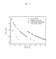
図4は、各符号長に対するTSLの計算値を示すグラフである。信号の復調は自己相関フィルタを用いて行っている。符号長M=25、符号長M=28、両者ともTSLが(2/M)以下となっている。
【0032】
図5は、拡張Barker符号と不整合フィルタのコンボリューション結果を示すグラフであり、符号長=28のA−code、B−codeをそれぞれ対応する不整合フィルタで構成される復調フィルタA、Bで復調した結果のうち、結果の悪い方を図に示す。
【0033】
図6はA−codeを復調フィルタBで復調した結果を示す。B−codeを復調フィルタAで復調した結果も図6と同様であり、図6に示すように、符号化による他符号圧縮率とフォーカスの効果を組み合わせることで、ノイズを画像のダイナミックレンジ外にすることが出来る。TSLは、不整合フィルタのタップ長さを増やせば増やす程低くできることが既に判明しているが、過度に長くすると必要なメモリサイズや計算時間の観点から不利となるので、これらのバランスを考慮して適宜タップ長さを設定する。
【0034】
図7、図8には、符号列の隣接符号間の時間間隔と超音波探触子から送波される超音波(キャリア)の中心周波数との関係を示す。図7は、キャリアの基本周期と符号化周期との関係を示す模式図である。図8は、符号化の周期とキャリアの基本周期の比とTSLとの関係を示す。図8より、符号間隔が送波キャリアの1/4周期の奇数倍、つまり図8のTcode/T0が0.25、0.75、1.25・・といった値の時にTSLが最小となることが分かる。したがって、符号列の間隔は送波キャリアの周期の1/4の奇数倍であることが好ましい。実際には、送波のD/Aコンバータのサンプリングレートや受信のA/Dコンバータのサンプリングレートで制限を受けるため、Tcode/T0を厳密に1/4の奇数倍に一致させるのは難しく、1/4の奇数倍からある程度ずれる。したがって、上記制限内で、おおよそ1/4の奇数倍であるような符号列間隔を選ぶことが望ましい。
【0035】
また、図8から明らかなように、Tcode/T0が1/4の奇数倍の位置におけるTSLの値は、Tcode/T0が大きくなると共に小さくなる。TSLを画像のダイナミックレンジの外に追いやるにはTSLを−60dB以下に押さえることができればよいので、Tcode/T0が大きくなれば、1/4の奇数倍からのずれの許容範囲は広がる。例えば、図8において、Tcode/T0=1。なお、前記の通り、符号間隔が長くなるほど、TSLは下がっていくが、符号間隔を長くするとその分送波信号のメモリのタップ数が必要となり、回路規模を大きくしてしまうことや、実際に送波される波形が長くなると距離分解能に影響を与えることがあり、符号間隔を長くする事には制約がある。しかしながら、いずれのTcode/T0の範囲の符号列間隔を使用するかということは、装置の設計上、適宜選択すれば良い事項であるので、Tcode/T0=0.25、0.75、あるいは図8に記載されていないTcode/T0の範囲で本発明の実施があり得ることは言うまでもない。
【0036】
以上のように、TSLを小さくするために最適な符号間隔を選ぶ構成とすることは複数ビーム送波のときのみならず、単数ビーム送波のときにおいても、TSLが画像を劣化するという、符号化送受信法の抱える重大な問題を解決する極めて有効な方法である。
【0037】
(実施例2)
図9は実施例2の超音波診断装置の構成例を示す図である。実施例2の構成はセクタ型探触子を用い、一つの口径から、別々の方向に同時送受信を行う点が、実施例1と異なる。探触子中の一つ一つの素子に着目すると、二つの符号の信号をそれぞれ別々の遅延時間を掛けた上で和を取った信号を送信していることになる。受信後はそれぞれの素子について和の信号を同じA/D変換器で、デジタル化したあと、同じ信号を二つの加算器に出力し、それぞれの焦点に対応する遅延時間を加えて加算を行い復調する。復調後の処理に関しては実施例1と同様である。この実施例の模式図を、図10に示す。
【0038】
(実施例3)
図11は、実施例3の超音波診断装置別の構成例を示す図である。本実施例においては、以降、探触子上の各素子で受信された受信信号であって、プリアンプ、A/Dコンバータ等を通過した後、整相加算する前の信号を、受信チャネル上の信号と呼ぶ。実施例3の構成は実施例1、2と次の点で異なる。実施例1、2では、生体からの反射信号をA/D変換した後に、受信チャネル上の信号の整相加算処理を行ない、次に、符号の復調を行なうが、実施例3では、生体からの反射信号をA/D変換した後に、復調フィルタとして重み付け不整合フィルタを用いて各受信チャネル上の信号に対して符号の復調を行ない、次に、整相加算処理を行なう。実施例1の復調では、不整合フィルタには重み付けがなされていない。
【0039】
以下、重み付け不整合フィルタについて説明する。なお、以下の説明で、記号B、Wは行列を示しc、f、d、wはベクトル、記号「T」は転置を、Bは送波符号を、fは復調フィルタを表す。
【0040】
まず、復調後の信号Cは、(式1)で与えられる。
【0041】
【数1】

I=Σ(ci−di)2=(fB−d)(fB−d)T
=fBBTfT−dBTfT−fBdT+ddT ・・・(式2)
(式2)に対して、
∂I/∂fi=0 ・・・(式3)
なる(式3)の条件を適用し、全てのi(i=1、2、・・、m)について∂I/∂fiを求めると、(式4)のようになる。
【0042】
【数2】
f=dBT(BBT)-1 ・・・(式6)
本実施例では、復調されるべき本来の信号のピーク近傍でのCとDの差をできるだけ小さくするため重みw(w1 2、w2 2、…、wn+m-1 2)を用いて、cとdの差に分布をもたせてfを求める。cとdの重み付き自乗誤差和Iが得られ、重み行列Wを以下の(式7)のように表記し、
【0043】
【数3】
I=Σ{wi 2(ci−di)2}
=(fBW−DW)(fBW−dW)T ・・・(式8)
重み付きの不整合フィルタは、(式9)により与えられる。
f=(dW)(BWT){(BW)(BW)T}-1 ・・・(式9)
Gauss関数等のように中心に近づくほど大きな重みを持つ重み関数を用いた重み付き不整合フィルタを用いることにより、復調されるべき本来の信号のピーク近傍の不要信号を大きく抑圧して、復調後も残る不要信号の位置を復調されるべき本来のピークから遠い位置に離すことができる。
【0044】
図12は、拡張Barker符号と重み付け不整合フィルタのコンボリューション結果を示すグラフである。不要信号を復調されるべき本来のピークから離した後に整相加算処理を行なうと、不要信号に関してはフォーカスの領域から外れるので、整相加算に対する寄与が下がるという効果が発生する。この効果は、F値(Fナンバー)にも依存するが典型的なF値が1程度の条件では、−10dB程度の効果がある。従って、実施例3の構成では、実施例1より更にTSLの抑圧レベルの改善が可能となる。
【0045】
撮像のシミュレーションによれば、実施例1の構成では、近距離焦点でのTSLは−60dB、遠距離焦点でのTSLは−50dB、他符号圧縮率は−9dBであり、実施例3の構成では、近距離焦点でのTSLは−80dB以下、遠距離焦点でのTSLは−50dB、他符号圧縮率は−9dBであった。重み付け不整合フィルタを使用することにより、近距離焦点でのTSLが大幅に改善されることが判明した。以上説明した実施例3の構成は、複数超音波ビームの符号化送受波を用いる3次元撮像のみに適用されるものでなく、符号化された単数の超音波ビームの送受波にも適用が可能である。
【0046】
(実施例4)
実施例4では、図1、図9、図11の構成に於いて、送波する符号と、復調するフィルタを入れ替える構成とする。即ち、送波符号メモリA(14a)にA−codeを復調する復調フィルタAを記憶し送波符号メモリB(14b)にB−codeを復調する復調フィルタBに記憶し、符号復調メモリA(17a)に拡張Barker符号(A−code)を記憶し、符号復調メモリB(17b)に拡張Barker符号(B−code)を記憶する。
【0047】
実施例4の構成では、図1、図9、図11の構成で復調フィルタとして用いていた符号系列で送波し、受波後に拡張Barker符号を用いて復調する。この結果、受波後の処理を行なうASIC内のメモリサイズを小さくできる。以上説明した実施例4の構成は、複数超音波ビームの符号化送受波を用いる3次元撮像のみに適用されるものでなく、符号化された単数の超音波ビームの送受波にも適用が可能である。
【0048】
(実施例5)
実施例5では、実施例1の符号の数を4本に増やした場合である。この場合、表1に表されるように全ての符号間の相間が−10dB以下程度という目標を満たすわけではない。しかし図13のように4本走査をするときに対角に位置する2本のビームとして、最も相間の悪いA、Cを使うことで符号の相互相間の悪さをフォーカスの効果で多少補うことが可能となる。よって、画質を優先するか、撮像速度を優先するかによって、使用者が切り替えるという形態で使用が可能となる。
【0049】
【表1】
【0050】
以上の各実施例で説明したように、本発明の超音波診断装置では、複数の振動子が2次元に配列される探触子から、生体に対して同時に複数の超音波ビームの送受波を行なう。各超音波ビームの送受波を行なう送受波口径の複数が送受波口径選択回路により選択される。各超音波ビームに対応して、送受波信号処理回路が設けられ、各送受波口径の振動子による超音波ビームの送受波の信号が処理される。画像処理部(信号処理器)で、各送受波信号処理回路の出力に種々の演算処理が施され、多数の2次元断層データから所望の視点から観察される3次元画像が生成される。3次元画像はほぼリアルタイムで表示装置に表示される。
【0051】
生体に対して同時に複数の超音波ビームの各超音波ビームに対応して設けられる送受波信号処理回路は、T/Rスイッチ11、パルサ(ドライバ)12、送波収束遅延制御部13、送波符号メモリ(14a又は14b)、プリアンプ、TGC(タイムゲインコントロール)アンプ、及びA/D変換器(15)、受波収束遅延制御部19、加算器(整相加算器)18、符号復調メモリ(17a又は17b)復調器16から構成される。
【0052】
本発明で使用される探触子では、例えば、超音波振動子が、短軸方向に64個、長軸方向に128個配列されている。超音波ビームの焦点は、1つの断層面内で、深さ方向、及び方位方向でそれぞれ走査される。
【0053】
本発明では、長軸方向に複数、例えば、2、4、6個の送受波口径が形成され、各送受波口径で相互に独立して超音波ビームの送受波が行なわれ、複数の断層面に関する断層像が得られる。各送受波口径で行なう超音波ビームの深さ方向、及び方位方向での走査(送受波)の制御により、長軸方向で相互にほぼ平行な異なる複数の断層面(例えば、64断層面)での断層像を得ることができる。各断層像は30msで得られる。
【0054】
この結果、複数の断層像により生体の3次元の撮像領域に関する3次元断層像データが得られる。所定の視点が予め設定され、3次元断層像データに対してレンダリング処理、陰影処理等の3次元表示のための演算処理がなされ、複数の断層像が撮像された後ほぼリアルタイムで、もしくは撮像面を逐次更新しながら、視点から観察される3次元画像が表示装置に表示される。
【0055】
先述のように、1本の超音波ビームの電子走査による撮像領域の撮像では、撮像速度は0.5画像/秒が限界である。しかし、以上説明した各実施例では、符号長M=28の拡張Barker符号の4通の符号のうちの2通りの符号(A−code、B−code)により符号化した2本の超音波ビームを同時に送受波して撮像領域を電子走査する(2−超音波ビーム走査)。
【0056】
2本の超音波ビームの各超音波ビームに対応して独立に動作する2つの送受波信号処理回路が設けられ、各超音波ビームは、撮像領域の1/2をそれぞれ独立して電子走査するので、各超音波ビームの走査範囲は1/2となり撮像速度が2倍になる。即ち、1画像/秒の撮像速度が実現できる。
【0057】
また、符号長M=28の拡張Barker符号の4通の符号により符号化した4本の超音波ビームを同時に送受波して撮像領域を電子走査することも可能である(4−超音波ビーム走査)。4本の超音波ビームの各超音波ビームに対応して独立に動作する4つの送受波信号処理回路が設けられ、各超音波ビームは、撮像領域の1/4をそれぞれ独立して電子走査するので、各超音波ビームの走査範囲は1/4となり撮像速度は4倍にできる。即ち、2画像/秒の撮像速度が実現できる。
【0058】
更に、符号長M=25の拡張Barker符号の2通りの符号、及び符号長M=28の拡張Barker符号の4通の符号の合計6通りを用いて2−、4−超音波ビーム走査を組み合わせることもできる(6−超音波ビーム走査)。この場合、1つの超音波ビーム走査しか行わない装置に比べて撮像速度は6倍になり、3画像/秒の撮像速度が実現される。6−超音波ビーム走査の装置構成においては、6つの超音波ビームに対応する送受波信号処理回路を設けて、これら6つの送受波信号処理回路から異なる数の送受波送信処理を選択する制御回路を設け、撮像速度を選択できる構成としても良い。例えば、6つの送受波送信処理回路から、1つの回路のみを選択すれば、撮像速度は0.5画像/秒となり、6つの回路を全て選択すれば撮像速度は、3画像/秒となる。すなわち、本発明により撮像モードが選択可能な装置が実現できることになる。
【0059】
【発明の効果】
本発明によれば、S/Nを大きく劣化させず撮像速度を向上させ、ほぼリアルタイムの3次元撮像が可能な超音波診断装置が可能となる。
【図面の簡単な説明】
【図1】本発明の実施例1の超音波診断装置の構成例を説明する図。
【図2】本発明に於ける複数超音ビームの符号化送受波による3次元撮像の概念を説明する図。
【図3】本発明に於ける超音波ビーム送信時の波面の様子の模式図。
【図4】本発明の実施例1で得られた各符号長に対するTSLの計算値を示すグラフ。
【図5】本発明の実施例1に於ける拡張Barker符号と不整合フィルタのコンボリューション結果を示すグラフ。
【図6】本発明の実施例1に於ける拡張Barker符号と他の符号に対する不整合フィルタのコンボリューション結果を示すグラフ。
【図7】本発明における、符号化間隔と送信信号の周期の関係の説明図。
【図8】本発明における、タイムサイドローブと符号化間隔対送信周期の関係を示すグラフ。
【図9】本発明の実施例2の超音波診断装置の構成例を示す図。
【図10】本発明の実施例2の複数超音ビームの符号化送受波による3次元撮像の概念を説明する図。
【図11】本発明の実施例3の超音波診断装置の構成例を示す図。
【図12】本発明の実施例3に於ける拡張Barker符号と重み付け不整合フィルタのコンボリューション結果を示すグラフ。
【図13】本発明の実施例5の4本ビーム超音波送受信の様子を模式的に説明する図。
【図14】本発明の実施例5の超音波診断装置の構成例を説明する図。
【符号の説明】
1…送受波口径−A、2…送受波口径−B、3…超音波ビームフォーマ、10…振動子列、11…T/Rスイッチ、12…パルサ、13…送波収束遅延制御部、14a…送波符号Aメモリ、14b…送波符号Bメモリ、15…プリアンプ、TGCアンプ、及びA/D変換器、16…復調器、17a…符号A復調フィルタ係数メモリ、17b…符号B復調フィルタ係数メモリ、18…加算器、19…受波収束遅延制御部、20…信号処理器、21…スキャンコンバータ、22…表示装置、30…送信信号形成部、101…口径一つあたりのビームフォーマと符号化送受信部、102…送受信ビーム本数制御部、103…ビーム本数選択入力部。[0001]
BACKGROUND OF THE INVENTION
The present invention relates to an ultrasonic diagnostic apparatus that images a living body using ultrasonic waves.
[0002]
[Prior art]
An ultrasonic diagnostic apparatus is an apparatus that obtains an image of an object by transmitting / receiving an ultrasonic beam to / from an object. From the viewpoint of reducing signal distortion and improving S / N, digitalization of signal processing, sign of an ultrasonic beam, and the like. It has been studied. For example, in the literature, IEEE TRANSACTION ON ULTRASONICS, FERROELECTRICS, AND FREQUENCY CONTROL, 39, No. 3, pp. 341 to 351 (1992), an encoded ultrasonic signal extended in the time axis direction is transmitted into the living body, and the signal reflected from the reflector in the living body is filtered by the time axis. A method of transmitting and receiving an ultrasonic beam that compresses in a direction is disclosed.
[0003]
In addition, in JP-A-11-309145, JP-A-11-309146, and JP-A-11-309147, an ultrasonic beam is encoded using a Baker code or a Golay code and encoded by a mismatch filter. An ultrasonic diagnostic apparatus for demodulating a generated ultrasonic beam is disclosed.
[0004]
[Problems to be solved by the invention]
In an ultrasonic diagnostic apparatus, improvement in imaging speed is very important. For example, in order to observe the heartbeat of the heart valve in real time, it is necessary to perform imaging at a speed of about 1 image / 30 ms. However, the imaging speed of the current ultrasonic diagnostic apparatus for 3D imaging is 1 image / It is about 2 seconds (about 0.5 image / second). The greatest factor that defines the limit of imaging time is the speed of sound in the living body, but the sound intensity in the living body is almost constant.
[0005]
If the imaging area is divided by simultaneous transmission / reception using multiple ultrasonic beams, the imaging speed per image will be improved. However, simply transmitting and receiving multiple ultrasonic beams will enable acoustic crosstalk, etc. As a result, the image quality deteriorates significantly. Also, in the field of wireless communication such as CDMA, a technique for encoding a signal using orthogonal codes and canceling crosstalk at the time of signal demodulation is known, but the Barker code that has been used for conventional ultrasonic coding is Since the codes have a code length of 5, 7, 11, and 13 and each has only one type, the crosstalk cannot be canceled due to the orthogonality of the codes. In general, the longer the code length, the easier the orthogonality of the code string appears. However, since the distance resolution of ultrasonic imaging decreases as the code length increases, the code length cannot be increased without limitation.
[0006]
Therefore, in the ultrasonic diagnostic apparatus for three-dimensional imaging according to the prior art, simultaneous transmission / reception of a plurality of ultrasonic beams cannot be realized, and the imaging speed is not at a level at which an object can be observed in real time.
[0007]
An object of the present invention is to provide an ultrasonic diagnostic apparatus that solves the above-described problems, improves the imaging speed without significant S / N degradation, and enables high-speed imaging.
[0008]
[Means for Solving the Problems]
The inventors of the present invention have developed a new code string suitable for encoding an ultrasonic beam. This code string is a code string in which the code length M is M> 13 and the maximum value of the time side lobe that appears before and after the peak on the time axis of the autocorrelation function is (2 / M) or less. In the present specification, this code string is hereinafter referred to as an extended Barker code.
[0009]
Here, the time side lobe is an unnecessary signal generated before and after the peak of the original signal to be demodulated when demodulating the encoded signal, and is generally always generated. . For the evaluation of the time side lobe, it is common to use a value normalized with the peak value of the original signal to be demodulated, the magnitude of the autocorrelation function as seen on the time axis. It is abbreviated as TSL (time side level). By performing the encoding and decoding processing of the ultrasonic beam using the extended Barker code, simultaneous transmission / reception of a plurality of ultrasonic beams can be realized. Since a plurality of encoded ultrasonic beams can be transmitted / received simultaneously, the imaging speed per image can be dramatically improved without deterioration in image quality.
[0010]
As a means for the demodulation process, a mismatch filter or a weighted mismatch filter (hereinafter also referred to as a weighted mismatch filter) is used. As a means for realizing the mismatch filter, the signal processing circuit system may be provided with a circuit for the mismatch filter itself, or may be realized by causing an arithmetic device such as a CPU or a microcomputer to perform an arithmetic processing of the filter processing. Also good.
[0011]
An ultrasonic probe is used as means for transmitting and receiving an ultrasonic beam. The ultrasonic probe has a structure in which a plurality of transducers (piezoelectric elements) are arranged two-dimensionally in the vertical and horizontal directions, and an aggregate of the transducers forms a transmission / reception aperture for transmitting and receiving ultrasonic beams. ing. The transmission / reception aperture may be singular or plural. When the transmission / reception aperture is single, the transmission convergence delay circuit multiplies the drive signal of the transducer by a delay time, and adjusts the timing of the transmitted ultrasonic waves to converge the ultrasonic waves to a plurality of focal points. A two-dimensional ultrasonic image (B-mode image) is obtained by scanning the focal point in a living body, and a three-dimensional image is obtained by combining a plurality of two-dimensional images.
[0012]
DETAILED DESCRIPTION OF THE INVENTION
Hereinafter, embodiments of the present invention will be described in detail with reference to the drawings.
[0013]
Example 1
FIG. 1 is a diagram illustrating a configuration example of the ultrasonic diagnostic apparatus according to the first embodiment. FIG. 2 is a diagram for explaining the concept of three-dimensional imaging using coded transmission / reception waves of a plurality of ultrasonic beams in the present invention.
[0014]
In the example shown in FIGS. 1 and 2, in a convex probe, a linear type probe, two encoded ultrasonic beams are transmitted / received at different transmission apertures -A (1) and transmission / reception apertures-B (2). This is an example of transmitting and receiving simultaneously. Here, the convex and linear scanning is a method in which the focal point is always in front of the transmission aperture, and the focal point is moved along with the aperture. A wavefront at a certain time is schematically shown in FIG. The focal point of the ultrasonic beam from the transmission / reception aperture -A at a certain time is FA, and the focal point of the ultrasonic beam from the transmission / reception aperture -B is FB. The ultrasonic signal encoded with the symbol A is simultaneously transmitted to the focal point FA, and the ultrasonic signal encoded with the symbol B is simultaneously transmitted to the focal point FB. The code length is a limit that does not impair the distance resolution, and is in a range of 30 wavelengths or less with respect to the wavelength of the resonance frequency of the probe.
[0015]
As is well known, the Barker code is a code in which the TSL is (1 / N) when the code length is N, but there is only one Barker code with the code length = 5, 7, 11, and 13. However, as a result of studying the code by paying attention to the height of the TSL, the
[0016]
A specific example of the extended Barker code for the case of code lengths M = 25 and M = 28 is shown below. However, the case where the order of the signs is reversed and the case where the signs are reversed are regarded as the same sign.
[0017]
When M = 25, there are two different codes, and the codes A and B, respectively,
A: {-1, 1, 1, -1, 1, 1, -1, 1, -1, 1, -1, 1, 1, 1, 1, 1, 1, -1, -1, -1 1, 1, -1, -1, -1}, and
B: {-1, 1, -1, -1, 1, 1, -1, 1, 1, -1, 1, -1, 1, -1, -1, -1, -1, -1, -1, -1, 1, 1, 1, -1, -1}.
[0018]
When M = 28, there are four different codes, and the codes A, B, C, and D are respectively
A: {-1, 1, 1, -1, 1, 1, -1, 1, 1, -1, 1, -1, 1, -1, 1, 1, 1, 1, 1, 1,- 1, -1, -1, 1, 1, -1, -1, -1}, B: {-1, 1, 1, 1, -1, -1, -1, -1, 1, 1, 1, -1, 1, 1, 1, -1, 1, 1, 1, -1, 1, 1, -1, 1, -1, -1, 1, -1}, C: {1,- 1, 1, 1, -1, -1, 1, -1, -1, 1, -1, 1, -1, 1, 1, 1, 1, 1, 1, 1, -1, -1, -1, 1, 1, 1, -1, -1}, and
D: {1, 1, -1, 1, 1, -1, 1, -1, -1, 1, -1, -1, -1, 1, -1, -1, -1, 1,- 1, -1, -1, 1, 1, 1, 1, -1, -1, -1}.
[0019]
In order to prevent the S / N deterioration of the ultrasonic image, it is necessary to improve the separation between the received signal based on the own code and the received signal based on another code. The conditions differ depending on the shape, focus, and position of the probe, but in the case of a linear probe, if the two focal points are separated as much as possible, that is, if the full aperture of the probe is separated by half, the effect of focus -50 dB can be suppressed for the type, and -54 dB for the convex type. Therefore, if the reflected signal of another code remaining in the signal demodulated by the demodulation filter that demodulates the own code is −10 dB to −6 dB, noise can be output outside the dynamic range of −60 dB. Of course, it goes without saying that the TSL of the received signal based on the own code needs to be sufficiently small.
[0020]
The extended Barker code is suitable for transmission and reception of ultrasonic beams because there are two or more types of codes with a TSL smaller than that of the Barker code and the same code length and a small absolute value of the peak of the cross-correlation function. In the example, two codes (referred to as A-code and B-code) out of four codes of an extended Barker code having a code length M = 28 are used. Here, if the maximum value of the absolute value of the cross-correlation function is about ½ to 3 of the maximum value of the absolute value of the autocorrelation function, 20 log (1/2) ≈−− in dB display. Since 6, 20 log (1/3) ≈−10, the size of other codes remaining in the own code can be suppressed to about −10 dB to −6 dB. Therefore, it is considered necessary for the orthogonality between codes that the maximum value of the absolute value of the cross-correlation function is about ½ or less of the maximum value of the absolute value of the autocorrelation function. Needless to say, the extended Barker code of this embodiment is also within this range.
[0021]
The transmission code memory A (14a) shown in FIG. 1 stores A-code, and the transmission code memory B (14b) stores B-code. A pulser (driver) 12 is driven at a code interval (10/7) λ using A-code and B-code. Through a T / R (transmission / reception switching switch) switch 11, transducers of transmission / reception apertures -A (1) and -B (2) selected from the
[0022]
As a result of electrically driving each transducer with the respective encoded signals, a waveform obtained by convolving the electrical signal that drives each transducer and the transfer function of each transducer is represented by a transmission / reception aperture diameter −A (1), -B (2) is transmitted into the living body as an ultrasonic signal encoded from each transducer. At this time, the transmission waves from the transducers having the transmission / reception aperture diameters -A (1) and -B (2) are shifted by the transmission convergence delay time matched with the focal point by the transmission convergence
[0023]
The ultrasonic beam transmitted into the living body from the transmitting and receiving apertures -A (1) and -B (2) is reflected at each point in the living body, and the reflected wave is transmitted and received at the transmitting and receiving apertures -A (1) and -B. It enters each vibrator of (2).
[0024]
The ultrasonic beam transmitted from the transmission / reception aperture -A (1) is reflected by the reflector at the focal point FA, and the reflected wave is incident on the transducers of the transmission / reception apertures -A (1) and -B (2). To do. The ultrasonic beam transmitted from the transmission / reception aperture -A (1) is reflected by a strong reflector in the living body, and the reflected wave is incident on the transducer having the transmission / reception aperture -B (2). On the other hand, the ultrasonic beam transmitted from the transmission / reception aperture diameter -B (2) is reflected by the reflector at the focal point FB, and the reflected wave has the transmission / reception aperture diameters -B (2) and -A (1). Incident on the vibrator. The ultrasonic beam transmitted from the transmission / reception aperture -B (2) is reflected by the strong reflector in the living body, and the reflected wave is incident on the transducer having the transmission / reception aperture -A (1).
[0025]
Therefore, the signals input to the transducers of the transmission / reception apertures -A (1) and -B (2) are reflected by the reflection points of the ultrasonic beams encoded by the A-code and the B-code. This is a composite wave of the reflected signal (sum wave). The transmission / reception signal processing circuits corresponding to the ultrasonic beams transmitted from the transmission / reception apertures -A (1) and -B (2) are pre-processed or post-processed from the phasing addition process. Processing for selectively demodulating reflected signals from the focal points FA and FB is performed.
[0026]
The reflected signal from the reflector in the living body is converted into an electric signal by each transducer of each transmission / reception aperture diameter, and via a T / R switch 11, a preamplifier, a TGC (time gain control) amplifier, and an A / D conversion. Amplified and A / D converted by the device (15). After the reception convergence delay time is given by the reception convergence
[0027]
The demodulation filter A that demodulates A-code is stored in the code demodulation memory A (17a), and the demodulation filter B that demodulates B-code is stored in the code demodulation memory B (17b). Since the output of the
[0028]
After the three-dimensional tomographic image data relating to the three-dimensional imaging region to be observed on the living body is obtained, the
[0029]
In the first embodiment, two ultrasonic beams are simultaneously transmitted and received. At this time, if the distance between the two ultrasonic beams is large in a series of scanning of the ultrasonic beams, the phasing is performed. When the signal from one focus is selectively extracted by the addition processing, the reflected signal (unnecessary signal) from the other focus is more efficiently suppressed by the effect of the phasing addition processing, and only the signal from one focus is extracted. I can expect that. For this reason, in a linear or convex probe, the ultrasonic beam is always scanned under the condition that the center interval of each transmission / reception aperture is half that of the
[0030]
In an actual apparatus, circuit elements for signal processing such as the above-described demodulation filter and code demodulation memory are often housed in one integrated circuit as a transmission / reception signal processing circuit. For example, in FIG. 1, the processing between the T / R switch 11 and the
[0031]
FIG. 4 is a graph showing calculated TSL values for each code length. Signal demodulation is performed using an autocorrelation filter. The code length M = 25, the code length M = 28, and both have a TSL of (2 / M) or less.
[0032]
FIG. 5 is a graph showing the convolution result of the extended Barker code and the mismatch filter. The demodulation filters A and B each include a mismatch filter corresponding to the A-code and B-code of code length = 28, respectively. Of the demodulated results, the worse one is shown in the figure.
[0033]
FIG. 6 shows the result of demodulating A-code with the demodulation filter B. FIG. The result of demodulating the B-code with the demodulation filter A is the same as in FIG. 6, and as shown in FIG. 6, the noise is outside the dynamic range of the image by combining the other code compression rate and the focus effect by encoding. I can do it. It has already been found that the TSL can be lowered by increasing the tap length of the mismatch filter, but if it is excessively long, it is disadvantageous from the viewpoint of the required memory size and calculation time. To set the tap length as appropriate.
[0034]
7 and 8 show the relationship between the time interval between adjacent codes in the code string and the center frequency of the ultrasonic wave (carrier) transmitted from the ultrasonic probe. FIG. 7 is a schematic diagram showing the relationship between the basic period of the carrier and the encoding period. FIG. 8 shows the relationship between the ratio of the encoding period and the basic period of the carrier and the TSL. From FIG. 8, the code interval is an odd multiple of 1/4 period of the transmission carrier, that is, Tcode / T in FIG.0It can be seen that TSL is minimized when the value is 0.25, 0.75, 1.25. Therefore, the code string interval is preferably an odd multiple of 1/4 of the period of the transmission carrier. Actually, Tcode / T is limited by the sampling rate of the transmitting D / A converter and the sampling rate of the receiving A / D converter.0Is exactly equal to an odd multiple of 1/4 and is somewhat deviated from an odd multiple of 1/4. Therefore, it is desirable to select a code string interval that is an odd multiple of about 1/4 within the above limit.
[0035]
As is clear from FIG. 8, Tcode / T0The value of TSL at an odd multiple of 1/4 is Tcode / T0Decreases with increasing. To drive the TSL out of the dynamic range of the image, it is sufficient if the TSL can be suppressed to −60 dB or less.0Increases, the allowable range of deviation from an odd multiple of 1/4 increases. For example, in FIG. 8, Tcode / T0= 1. As described above, as the code interval becomes longer, the TSL decreases. However, if the code interval is made longer, the number of taps in the memory of the transmission signal is required, which may increase the circuit scale, When the waveform to be transmitted becomes long, the distance resolution may be affected, and there is a limitation in increasing the code interval. However, any Tcode / T0Whether to use a code string interval in the range of is a matter that can be selected as appropriate in the design of the apparatus.0= 0.25, 0.75, or Tcode / T not described in FIG.0It goes without saying that the present invention can be carried out within the scope of the above.
[0036]
As described above, a configuration in which an optimal code interval is selected to reduce TSL is not only in the case of multi-beam transmission but also in the case of single beam transmission. This is an extremely effective method for solving a serious problem of the computerized transmission / reception method.
[0037]
(Example 2)
FIG. 9 is a diagram illustrating a configuration example of the ultrasonic diagnostic apparatus according to the second embodiment. The configuration of the second embodiment is different from the first embodiment in that a sector type probe is used and simultaneous transmission / reception is performed from one aperture in different directions. When attention is paid to each element in the probe, a signal obtained by summing the signals of two codes multiplied by different delay times is transmitted. After reception, the sum signal for each element is digitized by the same A / D converter, and then the same signal is output to the two adders, added with a delay time corresponding to each focus, and demodulated. To do. The processing after demodulation is the same as in the first embodiment. A schematic diagram of this embodiment is shown in FIG.
[0038]
(Example 3)
FIG. 11 is a diagram illustrating a configuration example of the ultrasonic diagnostic apparatus according to the third embodiment. In the present embodiment, the received signal received by each element on the probe after that passes through the preamplifier, the A / D converter, etc., and before the phasing addition is received on the reception channel. Called a signal. The configuration of the third embodiment differs from the first and second embodiments in the following points. In the first and second embodiments, after the A / D conversion of the reflected signal from the living body, the phasing addition processing of the signal on the reception channel is performed, and then the code is demodulated. After the A / D conversion of the reflected signal, the signal on each reception channel is demodulated using a weighted mismatch filter as a demodulation filter, and then a phasing addition process is performed. In the demodulation of the first embodiment, the mismatch filter is not weighted.
[0039]
Hereinafter, the weighting mismatch filter will be described. In the following description, symbols B and W indicate matrices, c, f, d, and w are vectors, and the symbol “T"Represents transposition, B represents a transmission code, and f represents a demodulation filter.
[0040]
First, the demodulated signal C is given by (Equation 1).
[0041]
[Expression 1]
I = Σ (ci-Di)2= (FB-d) (fB-d)T
= FBBTfT-DBTfT-FBdT+ DdT ... (Formula 2)
For (Equation 2)
∂I / ∂fi= 0 (Formula 3)
(Formula 3) is applied, and ∂I / ∂f for all i (i = 1, 2,..., M)iIs obtained as (Equation 4).
[0042]
[Expression 2]
f = dBT(BBT)-1 ... (Formula 6)
In this embodiment, the weight w (w) is used to minimize the difference between C and D near the peak of the original signal to be demodulated.1 2, W2 2... wn + m-1 2) To obtain f by giving a distribution to the difference between c and d. A weighted square error sum I of c and d is obtained, and a weight matrix W is expressed as (Equation 7) below,
[0043]
[Equation 3]
I = Σ {wi 2(Ci-Di)2}
= (FBW-DW) (fBW-dW)T ... (Formula 8)
The weighted mismatch filter is given by (Equation 9).
f = (dW) (BWT) {(BW) (BW)T}-1 ... (Formula 9)
By using a weighted mismatch filter that uses a weight function that has a greater weight as it approaches the center, such as a Gauss function, the unnecessary signal near the peak of the original signal to be demodulated is greatly suppressed, and after demodulation Further, the position of the remaining unnecessary signal can be separated from the original peak to be demodulated.
[0044]
FIG. 12 is a graph showing a convolution result of the extended Barker code and the weighted mismatch filter. If the phasing addition processing is performed after the unnecessary signal is separated from the original peak to be demodulated, the unnecessary signal is out of the focus area, and thus the effect of reducing the contribution to the phasing addition occurs. This effect depends on the F value (F number), but under a typical F value of about 1, there is an effect of about −10 dB. Therefore, in the configuration of the third embodiment, it is possible to further improve the TSL suppression level compared to the first embodiment.
[0045]
According to the imaging simulation, in the configuration of the first embodiment, the TSL at the near focus is -60 dB, the TSL at the far focus is -50 dB, and the other code compression rate is -9 dB. The TSL at the short distance focus was −80 dB or less, the TSL at the long distance focus was −50 dB, and the other code compression rate was −9 dB. It has been found that the use of the weighted mismatch filter significantly improves the TSL at the near focus. The configuration of the third embodiment described above is not only applied to three-dimensional imaging using encoded transmission / reception waves of a plurality of ultrasonic beams, but can also be applied to transmission / reception of a single encoded ultrasonic beam. It is.
[0046]
Example 4
In the fourth embodiment, in the configurations of FIGS. 1, 9, and 11, the code to be transmitted and the filter to be demodulated are interchanged. That is, the transmission code memory A (14a) stores the demodulation filter A for demodulating the A-code, the transmission code memory B (14b) stores the demodulation filter B for demodulating the B-code, and the code demodulation memory A ( The extended Barker code (A-code) is stored in 17a), and the extended Barker code (B-code) is stored in the code demodulation memory B (17b).
[0047]
In the configuration of the fourth embodiment, transmission is performed using the code sequence used as the demodulation filter in the configurations of FIGS. 1, 9, and 11, and demodulation is performed using the extended Barker code after reception. As a result, the memory size in the ASIC that performs processing after reception can be reduced. The configuration of the fourth embodiment described above is not only applied to three-dimensional imaging using encoded transmission / reception waves of a plurality of ultrasonic beams, but can also be applied to transmission / reception of a single encoded ultrasonic beam. It is.
[0048]
(Example 5)
In the fifth embodiment, the number of codes in the first embodiment is increased to four. In this case, as shown in Table 1, the inter-code correlation does not meet the target of about −10 dB or less. However, as shown in FIG. 13, when two beams are positioned diagonally when performing four scanning, by using A and C, which are the most incompatible with each other, the badness between the codes can be compensated somewhat by the focus effect. It becomes possible. Therefore, it is possible to use in a form in which the user switches depending on whether priority is given to image quality or imaging speed.
[0049]
[Table 1]
[0050]
As described in the above embodiments, in the ultrasonic diagnostic apparatus of the present invention, a plurality of ultrasonic beams are simultaneously transmitted to and received from a living body from a probe in which a plurality of transducers are arranged two-dimensionally. Do. A plurality of transmission / reception apertures for transmitting / receiving each ultrasonic beam are selected by the transmission / reception aperture selection circuit. Corresponding to each ultrasonic beam, a transmission / reception signal processing circuit is provided to process the transmission / reception signal of the ultrasonic beam by the transducer of each transmission / reception aperture. In the image processing unit (signal processor), various arithmetic processes are performed on the output of each transmission / reception signal processing circuit, and a three-dimensional image observed from a desired viewpoint is generated from a large number of two-dimensional tomographic data. The three-dimensional image is displayed on the display device almost in real time.
[0051]
A transmission / reception signal processing circuit provided corresponding to each ultrasonic beam of a plurality of ultrasonic beams simultaneously on a living body includes a T / R switch 11, a pulser (driver) 12, a transmission convergence
[0052]
In the probe used in the present invention, for example, 64 ultrasonic transducers are arranged in the short axis direction and 128 in the long axis direction. The focal point of the ultrasonic beam is scanned in the depth direction and the azimuth direction within one tomographic plane.
[0053]
In the present invention, a plurality of, for example, 2, 4, and 6 transmission / reception apertures are formed in the major axis direction, and ultrasonic beams are transmitted and received independently at each transmission / reception aperture. A tomogram is obtained. By controlling the scanning (transmission / reception wave) in the depth direction and the azimuth direction of the ultrasonic beam performed at each transmission / reception aperture diameter, a plurality of different tomographic planes (for example, 64 tomographic planes) substantially parallel to each other in the major axis direction. Can be obtained. Each tomographic image is obtained in 30 ms.
[0054]
As a result, three-dimensional tomographic image data relating to a three-dimensional imaging region of a living body is obtained from a plurality of tomographic images. A predetermined viewpoint is set in advance, calculation processing for three-dimensional display such as rendering processing and shading processing is performed on the three-dimensional tomographic image data, and a plurality of tomographic images are captured in almost real time or on the imaging surface Are sequentially updated, and a three-dimensional image observed from the viewpoint is displayed on the display device.
[0055]
As described above, in imaging of an imaging region by electronic scanning of one ultrasonic beam, the imaging speed is limited to 0.5 image / second. However, in each of the embodiments described above, two ultrasonic beams encoded by two codes (A-code, B-code) out of four codes of an extended Barker code having a code length M = 28. Are simultaneously transmitted and received to electronically scan the imaging region (2-ultrasonic beam scanning).
[0056]
Two transmission / reception signal processing circuits that operate independently corresponding to each ultrasonic beam of the two ultrasonic beams are provided, and each ultrasonic beam independently electronically scans a half of the imaging region. Therefore, the scanning range of each ultrasonic beam is halved and the imaging speed is doubled. That is, an imaging speed of 1 image / second can be realized.
[0057]
Further, it is also possible to simultaneously transmit and receive four ultrasonic beams encoded by four codes of an extended Barker code having a code length M = 28 to electronically scan the imaging region (4-ultrasonic beam scanning). ). Four transmission / reception signal processing circuits that operate independently corresponding to each of the four ultrasonic beams are provided, and each ultrasonic beam independently electronically scans a quarter of the imaging region. Therefore, the scanning range of each ultrasonic beam is ¼, and the imaging speed can be quadrupled. That is, an imaging speed of 2 images / second can be realized.
[0058]
Furthermore, 2-, 4-ultrasound beam scanning is combined using two kinds of codes of the extended Barker code of code length M = 25 and a total of six kinds of four codes of the extended Barker code of code length M = 28. (6-ultrasonic beam scanning). In this case, the imaging speed is 6 times that of an apparatus that performs only one ultrasonic beam scanning, and an imaging speed of 3 images / second is realized. In the apparatus configuration of 6-ultrasonic beam scanning, a transmission / reception signal processing circuit corresponding to six ultrasonic beams is provided, and a control circuit for selecting a different number of transmission / reception wave transmission processes from these six transmission / reception signal processing circuits It is good also as a structure which can provide imaging speed and can select. For example, if only one circuit is selected from six transmission / reception transmission processing circuits, the imaging speed is 0.5 images / second, and if all six circuits are selected, the imaging speed is 3 images / second. That is, an apparatus capable of selecting an imaging mode can be realized by the present invention.
[0059]
【The invention's effect】
According to the present invention, an ultrasonic diagnostic apparatus capable of improving imaging speed without greatly degrading S / N and capable of almost real-time three-dimensional imaging is possible.
[Brief description of the drawings]
FIG. 1 is a diagram illustrating a configuration example of an ultrasonic diagnostic apparatus according to a first embodiment of the present invention.
FIG. 2 is a diagram for explaining the concept of three-dimensional imaging using encoded transmission / reception waves of a plurality of supersonic beams in the present invention.
FIG. 3 is a schematic diagram of the state of a wavefront when transmitting an ultrasonic beam in the present invention.
FIG. 4 is a graph showing calculated values of TSL for each code length obtained in Example 1 of the present invention.
FIG. 5 is a graph showing a convolution result of an extended Barker code and a mismatch filter in
FIG. 6 is a graph showing a convolution filter convolution result for an extended Barker code and other codes in
FIG. 7 is an explanatory diagram of the relationship between the encoding interval and the cycle of the transmission signal in the present invention.
FIG. 8 is a graph showing the relationship between time side lobe and coding interval versus transmission period in the present invention.
FIG. 9 is a diagram illustrating a configuration example of an ultrasonic diagnostic apparatus according to a second embodiment of the present invention.
FIG. 10 is a diagram for explaining the concept of three-dimensional imaging using encoded transmission / reception waves of a plurality of supersonic beams according to the second embodiment of the present invention.
FIG. 11 is a diagram illustrating a configuration example of an ultrasonic diagnostic apparatus according to a third embodiment of the present invention.
FIG. 12 is a graph showing a convolution result of an extended Barker code and a weighted mismatch filter in
FIG. 13 is a diagram schematically illustrating a state of four-beam ultrasonic transmission / reception according to the fifth embodiment of the present invention.
FIG. 14 is a diagram illustrating a configuration example of an ultrasonic diagnostic apparatus according to a fifth embodiment of the present invention.
[Explanation of symbols]
DESCRIPTION OF
Claims (4)
前記複数の符号列の相互相関関数の絶対値の最大値は、自己相関関数の絶対値の最大値に比べ1/2以下であり、
前記超音波探触子は、超音波ビームが送受信される複数の口径を有し、該複数の口径に対応する複数の送受波信号処理回路と、該複数の送受波信号処理回路から任意の数の回路を選択する制御部とを有し、
前記送受波信号処理回路を選択することにより動作させる口径の数を切り替え、撮像速度を切り替えることを特徴とする超音波診断装置。An ultrasonic probe comprising means for transmitting a plurality of ultrasonic beams encoded by a plurality of code sequences, and a transmission / reception signal processing circuit for generating the code sequences,
The maximum value of the absolute value of the cross-correlation function of the plurality of code strings is 1/2 or less than the maximum value of the absolute value of the autocorrelation function,
The ultrasonic probe has a plurality of apertures through which an ultrasonic beam is transmitted and received, a plurality of transmission / reception signal processing circuits corresponding to the plurality of apertures, and an arbitrary number of the plurality of transmission / reception signal processing circuits A control unit for selecting the circuit of
An ultrasonic diagnostic apparatus, wherein the number of apertures to be operated is switched by selecting the transmission / reception signal processing circuit, and the imaging speed is switched.
前記超音波探触子より送信される符号列における符号の時間間隔は、該超音波探触子から送信される超音波の中心周波数の逆数の約1/4の奇数倍であり、
前記符号列は、符号長Mが13より大きく、前記自己相関関数のタイムサイドローブの最大値を自己相関関数の最大値で規格化した値が2/M以下であることを特徴とする超音波診断装置。An ultrasonic probe having a diameter for transmitting and receiving ultrasonic waves, and a transmission and reception signal processing circuit for generating a code string signal for driving the ultrasonic probe,
The time interval of the code in the code string transmitted from the ultrasonic probe is an odd multiple of about 1/4 of the inverse of the center frequency of the ultrasonic wave transmitted from the ultrasonic probe,
The code string has a code length M greater than 13, and a value obtained by normalizing the maximum value of the time side lobe of the autocorrelation function with the maximum value of the autocorrelation function is 2 / M or less. Diagnostic device.
前記送受波信号処理回路は、前記超音波ビームの送受波を行なう前記送受波口径を選択する送受波口径選択回路と、前記送受波口径の前記振動子の送波収束遅延時間を制御する送波収束遅延制御部と、前記符号列を記憶する送波符号メモリと、選択された前記送受波口径の前記振動子を前記符号化信号で駆動するドライバと、前記送受波口径の前記振動子による前記生体内からの反射信号をA/D変換するA/D変換器と、前記送受波口径の前記各振動子による前記反射信号に付与する受波収束遅延時間を制御する受波収束遅延制御部と、前記受波収束遅延時間が付与された前記反射信号を加算し整相加算処理を行なう整相加算器と、前記整相加算器の出力信号に対して前記符号化信号を復調する処理を行ない受波超音波ビームを求める復調フィルタを備える復調器とを有し、
複数の前記符号列の相互相関関数の絶対値の最大値が自己相関関数の絶対値の最大値に比べ1/2以下であり、
前記符号列は、符号長Mが13より大きく、前記自己相関関数のタイムサイドローブの最大値を自己相関関数の最大値で規格化した値が2/M以下であり、
前記送受波信号処理回路の数を選択する制御回路を有し、撮像速度を切り替えることを特徴とする超音波診断装置。An ultrasonic probe composed of two-dimensionally arranged transducers that simultaneously drive a plurality of transmission / reception apertures with encoded signals of different code sequences and transmit / receive a plurality of ultrasonic beams to / from a living body And a transmission / reception signal processing circuit that is provided corresponding to each ultrasonic beam and processes transmission / reception signals of each ultrasonic beam, and 2 obtained by arithmetic processing on the output of each transmission / reception signal processing circuit. An image processing unit that generates a three-dimensional image from the three-dimensional tomographic data, and a display device that displays the three-dimensional image,
The transmission / reception signal processing circuit includes a transmission / reception aperture selection circuit for selecting the transmission / reception aperture for performing transmission / reception of the ultrasonic beam, and a transmission wave for controlling a transmission convergence delay time of the transducer of the transmission / reception aperture. A convergence delay control unit, a transmission code memory for storing the code string, a driver for driving the transducer having the selected transmission / reception aperture with the encoded signal, and the transducer having the transmission / reception aperture An A / D converter for A / D-converting a reflected signal from the living body; and a received wave convergence delay control unit for controlling a received wave convergence delay time to be given to the reflected signal by each transducer of the transmission / reception aperture diameter; A phasing adder that performs phasing addition processing by adding the reflected signals to which the received wave convergence delay time is added, and a process of demodulating the encoded signal with respect to the output signal of the phasing adder. Demodulation for receiving ultrasonic beam And a demodulator with a filter,
The maximum value of the absolute value of the cross-correlation function of the plurality of code sequences is 1/2 or less than the maximum value of the absolute value of the autocorrelation function;
The code string has a code length M greater than 13, and a value obtained by normalizing the maximum value of the time side lobe of the autocorrelation function with the maximum value of the autocorrelation function is 2 / M or less,
An ultrasonic diagnostic apparatus having a control circuit for selecting the number of the transmission / reception signal processing circuits and switching an imaging speed.
前記送受波信号処理回路は、前記超音波ビームの送受波を行なう前記送受波口径を選択する送受波口径選択回路と、前記送受波口径の前記振動子の送波収束遅延時間を制御する送波収束遅延制御部と、前記符号列を記憶する送波符号メモリと、選択された前記送受波口径の前記振動子を前記符号化信号で駆動するドライバと、前記送受波口径の前記振動子による前記生体内からの反射信号をA/D変換するA/D変換器と、前記送受波口径の前記各振動子による前記反射信号に付与する受波収束遅延時間を制御する受波収束遅延制御部と、前記受波収束遅延時間が付与された前記反射信号を加算し整相加算処理を行なう整相加算器と、前記整相加算器の出力信号に対して前記符号化信号を復調する処理を行ない受波超音波ビームを求める復調フィルタを備える復調器とを有し、
複数の前記符号列の相互相関関数の絶対値の最大値が、自己相関関数の絶対値の最大値に比べ1/2以下であり、
前記符号列は、符号長Mが13より大きく、前記自己相関関数のタイムサイドローブの最大値を自己相関関数の最大値で規格化した値が2/M以下であり、
前記送受波信号処理回路の数を選択し前記超音波ビームの本数を入力する入力部を有することを特徴とする超音波診断装置。An ultrasonic probe composed of two-dimensionally arranged transducers that simultaneously drive a plurality of transmission / reception apertures with encoded signals of different code sequences and transmit / receive a plurality of ultrasonic beams to / from a living body And a transmission / reception signal processing circuit that is provided corresponding to each ultrasonic beam and processes transmission / reception signals of each ultrasonic beam, and 2 obtained by arithmetic processing on the output of each transmission / reception signal processing circuit. An image processing unit that generates a three-dimensional image from the three-dimensional tomographic data, and a display device that displays the three-dimensional image,
The transmission / reception signal processing circuit includes a transmission / reception aperture selection circuit for selecting the transmission / reception aperture for performing transmission / reception of the ultrasonic beam, and a transmission wave for controlling a transmission convergence delay time of the transducer of the transmission / reception aperture. A convergence delay control unit, a transmission code memory for storing the code string, a driver for driving the transducer having the selected transmission / reception aperture with the encoded signal, and the transducer having the transmission / reception aperture An A / D converter for A / D-converting a reflected signal from the living body; and a received wave convergence delay control unit for controlling a received wave convergence delay time to be given to the reflected signal by each transducer of the transmission / reception aperture diameter; A phasing adder that performs phasing addition processing by adding the reflected signals to which the received wave convergence delay time is added, and a process of demodulating the encoded signal with respect to the output signal of the phasing adder. Demodulation for receiving ultrasonic beam And a demodulator with a filter,
The maximum value of the absolute value of the cross-correlation function of the plurality of code strings is 1/2 or less than the maximum value of the absolute value of the autocorrelation function;
The code string has a code length M greater than 13, and a value obtained by normalizing the maximum value of the time side lobe of the autocorrelation function with the maximum value of the autocorrelation function is 2 / M or less,
An ultrasonic diagnostic apparatus comprising an input unit for selecting the number of the transmission / reception signal processing circuits and inputting the number of the ultrasonic beams.
Priority Applications (1)
| Application Number | Priority Date | Filing Date | Title |
|---|---|---|---|
| JP2001031965A JP3967882B2 (en) | 2001-02-08 | 2001-02-08 | Ultrasonic diagnostic equipment |
Applications Claiming Priority (1)
| Application Number | Priority Date | Filing Date | Title |
|---|---|---|---|
| JP2001031965A JP3967882B2 (en) | 2001-02-08 | 2001-02-08 | Ultrasonic diagnostic equipment |
Publications (3)
| Publication Number | Publication Date |
|---|---|
| JP2002233526A JP2002233526A (en) | 2002-08-20 |
| JP2002233526A5 JP2002233526A5 (en) | 2005-07-21 |
| JP3967882B2 true JP3967882B2 (en) | 2007-08-29 |
Family
ID=18895969
Family Applications (1)
| Application Number | Title | Priority Date | Filing Date |
|---|---|---|---|
| JP2001031965A Expired - Fee Related JP3967882B2 (en) | 2001-02-08 | 2001-02-08 | Ultrasonic diagnostic equipment |
Country Status (1)
| Country | Link |
|---|---|
| JP (1) | JP3967882B2 (en) |
Families Citing this family (3)
| Publication number | Priority date | Publication date | Assignee | Title |
|---|---|---|---|---|
| US7698948B2 (en) | 2003-12-02 | 2010-04-20 | Hitachi Medical Corporation | Ultrasonic diagnostic apparatus |
| JP5162923B2 (en) * | 2007-02-27 | 2013-03-13 | 株式会社日立製作所 | Ultrasonic imaging device |
| CN204017181U (en) * | 2013-03-08 | 2014-12-17 | 奥赛拉公司 | Aesthstic imaging and processing system, multifocal processing system and perform the system of aesthetic procedure |
Family Cites Families (15)
| Publication number | Priority date | Publication date | Assignee | Title |
|---|---|---|---|---|
| JPS5276956A (en) * | 1975-12-22 | 1977-06-28 | Hitachi Medical Corp | Method of measuring flowing velocity using doppler effect caused by modulated signal of m series |
| JPS61176331A (en) * | 1985-01-31 | 1986-08-08 | 株式会社東芝 | Ultrasonic diagnostic apparatus |
| JP2619446B2 (en) * | 1987-12-21 | 1997-06-11 | 株式会社日立製作所 | Ultrasound diagnostic equipment |
| JPH0781993B2 (en) * | 1989-04-05 | 1995-09-06 | 三菱電機株式会社 | Ultrasonic measuring device |
| JPH0838473A (en) * | 1994-07-29 | 1996-02-13 | Hitachi Medical Corp | Ultrasonic diagnostic device |
| US6134264A (en) * | 1995-02-01 | 2000-10-17 | Hitachi, Ltd. | Spread spectrum communication device and communication system |
| JPH10177072A (en) * | 1996-12-17 | 1998-06-30 | Ge Yokogawa Medical Syst Ltd | Ultrasonic image pickup method, and device therefor |
| JP4582827B2 (en) * | 1998-02-10 | 2010-11-17 | 株式会社東芝 | Ultrasonic diagnostic equipment |
| JP2909535B1 (en) * | 1998-02-17 | 1999-06-23 | 防衛庁技術研究本部長 | Pulse compression method and apparatus |
| JPH11309146A (en) * | 1998-03-26 | 1999-11-09 | General Electric Co <Ge> | System and method for imaging flow of ultrasonic scatterer |
| US6095977A (en) * | 1998-03-26 | 2000-08-01 | Hall; Anne Lindsay | Method and apparatus for color flow imaging using Golay-coded excitation on transmit and pulse compression on receive |
| JP4260920B2 (en) * | 1998-05-13 | 2009-04-30 | 株式会社東芝 | Ultrasonic diagnostic equipment |
| JP4903928B2 (en) * | 1999-04-23 | 2012-03-28 | ゼネラル・エレクトリック・カンパニイ | Three-dimensional flow imaging method and apparatus using coded excitation |
| JP3302946B2 (en) * | 1999-07-01 | 2002-07-15 | 松下電器産業株式会社 | Ultrasonic transmission / reception method and ultrasonic diagnostic apparatus |
| JP4698003B2 (en) * | 2000-07-27 | 2011-06-08 | アロカ株式会社 | Ultrasonic diagnostic equipment |
-
2001
- 2001-02-08 JP JP2001031965A patent/JP3967882B2/en not_active Expired - Fee Related
Also Published As
| Publication number | Publication date |
|---|---|
| JP2002233526A (en) | 2002-08-20 |
Similar Documents
| Publication | Publication Date | Title |
|---|---|---|
| US11559277B2 (en) | Ultrasound 3D imaging system | |
| US10426435B2 (en) | Ultrasound 3D imaging system | |
| JP5174010B2 (en) | Method and transducer array with integrated beaming | |
| US6436047B1 (en) | Aperture configurations for medical diagnostic ultrasound | |
| US8551000B2 (en) | Ultrasound 3D imaging system | |
| US6048315A (en) | Method and apparatus for ultrasonic synthetic transmit aperture imaging using orthogonal complementary codes | |
| US6790182B2 (en) | Ultrasound system and ultrasound diagnostic apparatus for imaging scatterers in a medium | |
| US6113545A (en) | Ultrasonic beamforming with improved signal-to-noise ratio using orthogonal complementary sets | |
| JP5649576B2 (en) | 3D ultrasonic imaging system | |
| KR100432617B1 (en) | Apparatus and method for forming ultrasound images using a set of golay codes with orthogonal property | |
| EP0859242A1 (en) | High resolution ultrasonic imaging through interpolation of received scanline data | |
| JP2000232978A (en) | Ultrasonic image pickup for optimizing image quality in region of interest | |
| US6730033B2 (en) | Two dimensional array and methods for imaging in three dimensions | |
| JP2003010181A (en) | Ultrasonic imaging method and device therefor using orthogonal golay code | |
| US20130338506A1 (en) | Method and apparatus for performing 3-dimensional ultrasound volume scanning by using 2-dimensional transducer array | |
| JP2001314400A (en) | Tissue generating higher harmonic-enhanced imaging using encoding excitation | |
| US6733453B2 (en) | Elevation compounding for ultrasound imaging | |
| JP3967882B2 (en) | Ultrasonic diagnostic equipment | |
| JP2005131407A (en) | Method and device for single transmission golay encoding excitation | |
| Tamraoui et al. | Complete Complementary Coded Excitation Scheme for SNR Improvement of 2D Sparse Array Ultrasound Imaging | |
| US20230346344A1 (en) | Ultrasound 3d imaging system | |
| Kim et al. | Hybrid beamformation for volumetric ultrasound imaging scanners using 2-D array transducers | |
| KR20010077539A (en) | Method and apparatus for interlaced multi-beam focusing for use in ultrasound imaging system | |
| JP2005192867A (en) | Ultrasonic diagnostic equipment | |
| JP2004201864A (en) | Ultrasonic imaging device and the ultrasonic imaging method |
Legal Events
| Date | Code | Title | Description |
|---|---|---|---|
| A521 | Written amendment |
Free format text: JAPANESE INTERMEDIATE CODE: A523 Effective date: 20041201 |
|
| A621 | Written request for application examination |
Free format text: JAPANESE INTERMEDIATE CODE: A621 Effective date: 20041201 |
|
| A977 | Report on retrieval |
Free format text: JAPANESE INTERMEDIATE CODE: A971007 Effective date: 20061023 |
|
| A131 | Notification of reasons for refusal |
Free format text: JAPANESE INTERMEDIATE CODE: A131 Effective date: 20061107 |
|
| A521 | Written amendment |
Free format text: JAPANESE INTERMEDIATE CODE: A523 Effective date: 20061220 |
|
| RD02 | Notification of acceptance of power of attorney |
Free format text: JAPANESE INTERMEDIATE CODE: A7422 Effective date: 20061220 |
|
| A131 | Notification of reasons for refusal |
Free format text: JAPANESE INTERMEDIATE CODE: A131 Effective date: 20070220 |
|
| A521 | Written amendment |
Free format text: JAPANESE INTERMEDIATE CODE: A523 Effective date: 20070412 |
|
| TRDD | Decision of grant or rejection written | ||
| A01 | Written decision to grant a patent or to grant a registration (utility model) |
Free format text: JAPANESE INTERMEDIATE CODE: A01 Effective date: 20070508 |
|
| A61 | First payment of annual fees (during grant procedure) |
Free format text: JAPANESE INTERMEDIATE CODE: A61 Effective date: 20070601 |
|
| R150 | Certificate of patent or registration of utility model |
Free format text: JAPANESE INTERMEDIATE CODE: R150 |
|
| FPAY | Renewal fee payment (event date is renewal date of database) |
Free format text: PAYMENT UNTIL: 20110608 Year of fee payment: 4 |
|
| FPAY | Renewal fee payment (event date is renewal date of database) |
Free format text: PAYMENT UNTIL: 20110608 Year of fee payment: 4 |
|
| FPAY | Renewal fee payment (event date is renewal date of database) |
Free format text: PAYMENT UNTIL: 20120608 Year of fee payment: 5 |
|
| FPAY | Renewal fee payment (event date is renewal date of database) |
Free format text: PAYMENT UNTIL: 20120608 Year of fee payment: 5 |
|
| FPAY | Renewal fee payment (event date is renewal date of database) |
Free format text: PAYMENT UNTIL: 20130608 Year of fee payment: 6 |
|
| LAPS | Cancellation because of no payment of annual fees |