JP3966552B2 - Solenoid device - Google Patents
Solenoid device Download PDFInfo
- Publication number
- JP3966552B2 JP3966552B2 JP2004122395A JP2004122395A JP3966552B2 JP 3966552 B2 JP3966552 B2 JP 3966552B2 JP 2004122395 A JP2004122395 A JP 2004122395A JP 2004122395 A JP2004122395 A JP 2004122395A JP 3966552 B2 JP3966552 B2 JP 3966552B2
- Authority
- JP
- Japan
- Prior art keywords
- operation shaft
- spring member
- shaft
- plunger
- distal end
- Prior art date
- Legal status (The legal status is an assumption and is not a legal conclusion. Google has not performed a legal analysis and makes no representation as to the accuracy of the status listed.)
- Expired - Lifetime
Links
Images


Landscapes
- Electromagnets (AREA)
Description
本発明は、コイルへの通電によってプランジャーがコイルの中心軸線方向に駆動され、プランジャーの先端部に捻じ込み連結された操作軸によって、所定のスイッチ動作、検出動作、制御動作あるいはロック動作等がなされるソレノイド装置に関する。 In the present invention, a plunger is driven in the direction of the central axis of the coil by energizing the coil, and a predetermined switch operation, detection operation, control operation, lock operation, or the like is performed by an operation shaft that is screwed into the distal end portion of the plunger. The present invention relates to a solenoid device.
図3に示したように一般のソレノイド装置では、ベース板1にコイル3が固定され、長さ方向の中心軸線をコイル3の中心軸線に整列させてプランジャー4がコイル4の中央空洞部に配置され、プランジャー4の先端部に連結された操作軸5の先端部がベース板1のガイド板部2の軸孔11に嵌挿されている(特許文献1参照)。
As shown in FIG. 3, in the general solenoid device, the coil 3 is fixed to the
比較的小型タイプのソレノイド装置では、プランジャー4と操作軸5の相互連結は捻じ込みによってなされており、典型的にはプランジャー4の先端部に中心軸線方向に螺子棒受孔13を形成し、操作軸6の基端部に中心軸線方向に螺子孔14を形成し、プランジャーの螺子棒受孔13に螺子孔12の基端部をに挿入固着し、螺子棒12の先端部の螺子部15を操作軸5の螺子孔14に捻じ込んでいる。
In a relatively small type solenoid device, the
このような捻じ込み連結式のソレノイド装置では、加工誤差によって、螺子棒受孔13がプランジャー4の中心軸線上に正確に形成されていないとき、あるいは、螺子孔14が操作軸5の中心軸線上に正確に形成されていないとき、もしくは、組付け誤差によって操作軸5の中心軸線がコイル3及びプランジャー4の中心軸線と正しく整列していないときには、軸孔11の内周面と操作軸5の外周面との間に擦れや齧りが発生してしまい、操作軸5とプランジャー4がスムーズに作動しなくなることがある。
In such a screw-coupled solenoid device, when the screw
本発明の課題は、加工誤差や組付け誤差によって操作軸の中心軸線がコイル及びプランジャーの中心軸線と正しく整列していない場合であっても、軸孔の内周面と操作軸の外周面との間に擦れや齧りが発生しないため、操作軸とプランジャーがスムーズに作動するソレノイド装置を提供することである。 The problem of the present invention is that the inner peripheral surface of the shaft hole and the outer peripheral surface of the operation shaft are obtained even when the center axis of the operation shaft is not correctly aligned with the central axis of the coil and the plunger due to processing errors or assembly errors Therefore, there is provided a solenoid device in which the operation shaft and the plunger operate smoothly because no rubbing or turning occurs between them.
本発明の主たる特徴は、コイル3の中心軸線上にプランジャー4が配置され、前記プランジャー4の先端部に操作軸5が捻じ込み連結され、前記操作軸5がガイド板部2の軸孔11に嵌挿されたソレノイド装置において、
前記操作軸5を前記軸孔11に嵌挿される先端側部分7と、前記プランジャー4に捻じ込み連結される基端側部分6とに分割して構成し、操作軸5の前記基端側部分6の先端面中央にバネ部材受孔9を中心軸線方向に形成し、操作軸5の前記先端側部分7の基端面中央にバネ部材受孔10を中心軸線方向に形成し、前記プランジャー4の中心軸線に対して撓曲変位可能なコイルバネ部材8の基端部を操作軸5の基端側部分6の前記バネ部材受孔9に挿入して、前記コイルバネ部材8を前記操作軸5の基端側部分6に固着し、前記コイルバネ部材8の先端部を操作軸の先端側部分7の前記バネ部材受孔10に挿入して、前記コイルバネ部材8を前記操作軸5の先端側部分7に固着したことである。
The main feature of the present invention, the
The
本発明のソレノイド装置では、操作軸5が前記軸孔11に嵌挿される先端側部分7と前記プランジャー4に捻じ込み連結される基端側部分6に分割して構成されており、操作軸5の前記基端側部分6の先端面中央にバネ部材受孔9を中心軸線方向に形成し、操作軸5の前記先端側部分7の基端面中央にバネ部材受孔10を中心軸線方向に形成し、前記プランジャー4の中心軸線に対して撓曲変位可能なコイルバネ部材8の基端部を操作軸5の基端側部分6の前記バネ部材受孔9に挿入して、前記コイルバネ部材8を前記操作軸5の基端側部分6に固着し、前記コイルバネ部材8の先端部を操作軸の先端側部分7の前記バネ部材受孔10に挿入して、前記コイルバネ部材8を前記操作軸5の先端側部分7に固着してあるため、前記した加工誤差や組付け誤差によって操作軸5の中心軸線がコイル3及びプランジャー4の中心軸線と正しく整列していない状況であっても、ガイド板部2の軸孔11の内周面と操作軸5の外周面との間に無用の擦れや齧りが発生することがなく、操作軸5とプランジャー4がスムーズに作動する。
In the solenoid device of the present invention, the
前記コイルバネ部材8としては、通常は圧縮コイルバネを使用する。圧縮コイルバネとしては、プランジャー4が動作方向に移動したときの操作軸5の即時応答性を考慮すれば、密に巻かれたコイルバネ(無負荷時において隣り合う線部分同士が密接しているもの)が望ましい。
As the
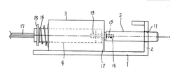
図1から図3に示した実施例では、所要回数及び長さに巻かれたコイル線と、これを支持するヨーク体との集合体であるコイル3は、目的の機器への装着に使用されるベース板1の主体部分に固着されている。ベース板1の一端にはガイド板部2が主体部分に直角に立ち上げられており、ガイド板部2の中央部には、コイル3の中心軸線の延長上に中心を合わせて軸孔11が形成されている。
In the embodiment shown in FIGS. 1 to 3, the coil 3, which is an assembly of a coil wire wound to a required number and length and a yoke body that supports the coil wire, is used for mounting to a target device. The
長さ方向の中心軸線をコイル3の中心軸線に整列させてコイル3の中央空洞部に挿入されたプランジャー4には、その先端部に螺子棒受孔13がプランジャー4の中心軸線方向に形成されている。螺子棒受孔13には、螺子棒12の基端部が挿入され、加締め固定または溶接、接着などの適宜方法によって固着されている。なお、螺子棒12部分をプランジャー4と一体物に形成することもできる。
The
操作軸5は、相対的に短い基端側部分6と長い先端側部分7とに分割して構成されている。操作軸5の基端側部分6の基端面中央には、螺子孔14が中心軸線方向に形成されている。螺子孔14には、前記螺子棒12の螺子部15が捻じ込まれる。
操作軸5の基端側部分の先端面中央には、バネ部材受孔が中心軸線方向に形成されている。操作軸5の先端側部分7の基端面中央にはバネ部材受孔10が中心軸線方向に形成されている。
The
A spring member receiving hole is formed in the center axis direction at the center of the distal end surface of the base end side portion of the
コイルバネ部材8は密に巻かれた圧縮コイルバネによって構成されており、コイルバネ部材8の基端部
は、操作軸5の基端側部分6のバネ部材受孔9に密に挿入され、溶接や接着などの適宜方法によって基端側部分6に固着される。バネ部材8の先端部は、操作軸5の先端側部分7のバネ部材受孔10に密に挿入され、溶接や接着などの適宜方法によって先端側部分6に固着される。
The
プランジャー4の基端部には圧縮コイルバネよりなる復帰用バネ16が嵌められており、プランジャー4が動作方向に移動したとき、復帰用バネ16はバネ受体18とコイル3のヨーク部と間において圧縮される。給電線17からなされるコイル3への通電が遮断されたとき、プランジャー4と操作軸5は原位置に復帰させられる。
A
1 ベース板
2 ガイド板部
3 コイル
4 プランジャー
5 操作軸
6 操作軸の基端側部分
7 操作軸の先端側部分
8 バネ部材
9 バネ部材受孔
10 バネ部材受孔
11 軸孔
12 螺子棒
13 螺子棒受孔
14 螺子孔
15 螺子部
16 復帰用バネ
17 給電線
18 バネ受体
DESCRIPTION OF
Claims (1)
前記操作軸5を前記軸孔11に嵌挿される先端側部分7と、前記プランジャー4に捻じ込み連結される基端側部分6とに分割して構成し、操作軸5の前記基端側部分6の先端面中央にバネ部材受孔9を中心軸線方向に形成し、操作軸5の前記先端側部分7の基端面中央にバネ部材受孔10を中心軸線方向に形成し、前記プランジャー4の中心軸線に対して撓曲変位可能なコイルバネ部材8の基端部を操作軸5の基端側部分6の前記バネ部材受孔9に挿入して、前記コイルバネ部材8を前記操作軸5の基端側部分6に固着し、前記コイルバネ部材8の先端部を操作軸の先端側部分7の前記バネ部材受孔10に挿入して、前記コイルバネ部材8を前記操作軸5の先端側部分7に固着したことを特徴とするソレノイド装置。 Plunger 4 is disposed on the central axis of the coil 3, the a tip portion of the plunger 4 is operating shaft 5 is connected screwing, the operation shaft 5 is inserted into the shaft hole 11 of the guide plate portion 2 solenoid In the device
The operating shaft 5 and the distal portion 7 which is inserted into the shaft hole 11, the configured by being divided into a proximal portion 6 which is connected screwing to the plunger 4, the base end side of the operation shaft 5 A spring member receiving hole 9 is formed in the center axis direction in the center of the distal end surface of the portion 6, and a spring member receiving hole 10 is formed in the center axis direction in the center of the base end surface of the distal end side portion 7 of the operation shaft 5. 4 is inserted into the spring member receiving hole 9 of the base end side portion 6 of the operation shaft 5 so that the coil spring member 8 can be flexibly displaced with respect to the central axis of the operation shaft 5. The distal end portion of the coil spring member 8 is inserted into the spring member receiving hole 10 of the distal end portion 7 of the operation shaft, and the coil spring member 8 is inserted into the distal end portion of the operation shaft 5. 7. A solenoid device fixed to 7 .
Priority Applications (1)
| Application Number | Priority Date | Filing Date | Title |
|---|---|---|---|
| JP2004122395A JP3966552B2 (en) | 2004-04-19 | 2004-04-19 | Solenoid device |
Applications Claiming Priority (1)
| Application Number | Priority Date | Filing Date | Title |
|---|---|---|---|
| JP2004122395A JP3966552B2 (en) | 2004-04-19 | 2004-04-19 | Solenoid device |
Publications (2)
| Publication Number | Publication Date |
|---|---|
| JP2005310850A JP2005310850A (en) | 2005-11-04 |
| JP3966552B2 true JP3966552B2 (en) | 2007-08-29 |
Family
ID=35439297
Family Applications (1)
| Application Number | Title | Priority Date | Filing Date |
|---|---|---|---|
| JP2004122395A Expired - Lifetime JP3966552B2 (en) | 2004-04-19 | 2004-04-19 | Solenoid device |
Country Status (1)
| Country | Link |
|---|---|
| JP (1) | JP3966552B2 (en) |
-
2004
- 2004-04-19 JP JP2004122395A patent/JP3966552B2/en not_active Expired - Lifetime
Also Published As
| Publication number | Publication date |
|---|---|
| JP2005310850A (en) | 2005-11-04 |
Similar Documents
| Publication | Publication Date | Title |
|---|---|---|
| JP4844672B2 (en) | Linear solenoid | |
| US8264313B2 (en) | Linear solenoid for vehicle | |
| JP4924519B2 (en) | Drive device and drive device manufacturing method | |
| JP6265943B2 (en) | Fluid control valve | |
| JP2017040304A (en) | Driving force transmission device | |
| US20090032752A1 (en) | Linear solenoid | |
| WO2010038564A1 (en) | Driving device and imaging device | |
| US9145957B2 (en) | Motor having screw joint | |
| WO2010107053A1 (en) | Universal tightening tool and tightening device using same | |
| JP3966552B2 (en) | Solenoid device | |
| JP2003148298A (en) | solenoid valve | |
| KR20170030026A (en) | Solenoid Valve | |
| JP4358287B1 (en) | Manual release mechanism of electromagnetic brake | |
| JP4237114B2 (en) | solenoid valve | |
| JP2011061895A (en) | Ultrasonic motor mechanism | |
| JP2008016281A (en) | magnetic switch | |
| JP2011112187A (en) | Non-excitation operation type electromagnetic brake and method for manufacturing the same | |
| JP4587983B2 (en) | Solenoid valve mounting structure | |
| JP5245126B2 (en) | Drive device | |
| WO2011058609A1 (en) | Joint structure | |
| JP6614490B2 (en) | Position detection sensor | |
| JP6579823B2 (en) | Spring load adjusting device and spring load adjusting method | |
| KR20210034067A (en) | Solenoid | |
| JP4158675B2 (en) | solenoid valve | |
| JP6611935B2 (en) | Turbo actuator |
Legal Events
| Date | Code | Title | Description |
|---|---|---|---|
| A977 | Report on retrieval |
Free format text: JAPANESE INTERMEDIATE CODE: A971007 Effective date: 20060811 |
|
| A131 | Notification of reasons for refusal |
Free format text: JAPANESE INTERMEDIATE CODE: A131 Effective date: 20060825 |
|
| A02 | Decision of refusal |
Free format text: JAPANESE INTERMEDIATE CODE: A02 Effective date: 20061215 |
|
| A521 | Request for written amendment filed |
Free format text: JAPANESE INTERMEDIATE CODE: A523 Effective date: 20070104 |
|
| A911 | Transfer to examiner for re-examination before appeal (zenchi) |
Free format text: JAPANESE INTERMEDIATE CODE: A911 Effective date: 20070220 |
|
| TRDD | Decision of grant or rejection written | ||
| A01 | Written decision to grant a patent or to grant a registration (utility model) |
Free format text: JAPANESE INTERMEDIATE CODE: A01 Effective date: 20070528 |
|
| A61 | First payment of annual fees (during grant procedure) |
Free format text: JAPANESE INTERMEDIATE CODE: A61 Effective date: 20070528 |
|
| R150 | Certificate of patent or registration of utility model |
Free format text: JAPANESE INTERMEDIATE CODE: R150 Ref document number: 3966552 Country of ref document: JP Free format text: JAPANESE INTERMEDIATE CODE: R150 |
|
| FPAY | Renewal fee payment (event date is renewal date of database) |
Free format text: PAYMENT UNTIL: 20110608 Year of fee payment: 4 |
|
| FPAY | Renewal fee payment (event date is renewal date of database) |
Free format text: PAYMENT UNTIL: 20110608 Year of fee payment: 4 |
|
| FPAY | Renewal fee payment (event date is renewal date of database) |
Free format text: PAYMENT UNTIL: 20120608 Year of fee payment: 5 |
|
| FPAY | Renewal fee payment (event date is renewal date of database) |
Free format text: PAYMENT UNTIL: 20130608 Year of fee payment: 6 |
|
| EXPY | Cancellation because of completion of term |