JP3964466B2 - Biopsy forceps instrument with irrigation and suction capabilities - Google Patents
Biopsy forceps instrument with irrigation and suction capabilities Download PDFInfo
- Publication number
- JP3964466B2 JP3964466B2 JP52670998A JP52670998A JP3964466B2 JP 3964466 B2 JP3964466 B2 JP 3964466B2 JP 52670998 A JP52670998 A JP 52670998A JP 52670998 A JP52670998 A JP 52670998A JP 3964466 B2 JP3964466 B2 JP 3964466B2
- Authority
- JP
- Japan
- Prior art keywords
- jaw
- biopsy forceps
- conduit
- movable
- tubular member
- Prior art date
- Legal status (The legal status is an assumption and is not a legal conclusion. Google has not performed a legal analysis and makes no representation as to the accuracy of the status listed.)
- Expired - Fee Related
Links
Images


Classifications
-
- A—HUMAN NECESSITIES
- A61—MEDICAL OR VETERINARY SCIENCE; HYGIENE
- A61B—DIAGNOSIS; SURGERY; IDENTIFICATION
- A61B10/00—Other methods or instruments for diagnosis, e.g. instruments for taking a cell sample, for biopsy, for vaccination diagnosis; Sex determination; Ovulation-period determination; Throat striking implements
- A61B10/02—Instruments for taking cell samples or for biopsy
- A61B10/0233—Pointed or sharp biopsy instruments
- A61B10/0266—Pointed or sharp biopsy instruments means for severing sample
-
- A—HUMAN NECESSITIES
- A61—MEDICAL OR VETERINARY SCIENCE; HYGIENE
- A61B—DIAGNOSIS; SURGERY; IDENTIFICATION
- A61B10/00—Other methods or instruments for diagnosis, e.g. instruments for taking a cell sample, for biopsy, for vaccination diagnosis; Sex determination; Ovulation-period determination; Throat striking implements
- A61B10/02—Instruments for taking cell samples or for biopsy
- A61B10/06—Biopsy forceps, e.g. with cup-shaped jaws
-
- A—HUMAN NECESSITIES
- A61—MEDICAL OR VETERINARY SCIENCE; HYGIENE
- A61B—DIAGNOSIS; SURGERY; IDENTIFICATION
- A61B10/00—Other methods or instruments for diagnosis, e.g. instruments for taking a cell sample, for biopsy, for vaccination diagnosis; Sex determination; Ovulation-period determination; Throat striking implements
- A61B10/02—Instruments for taking cell samples or for biopsy
- A61B2010/0225—Instruments for taking cell samples or for biopsy for taking multiple samples
-
- A—HUMAN NECESSITIES
- A61—MEDICAL OR VETERINARY SCIENCE; HYGIENE
- A61B—DIAGNOSIS; SURGERY; IDENTIFICATION
- A61B17/00—Surgical instruments, devices or methods, e.g. tourniquets
- A61B17/28—Surgical forceps
- A61B17/29—Forceps for use in minimally invasive surgery
- A61B2017/2926—Details of heads or jaws
- A61B2017/2932—Transmission of forces to jaw members
- A61B2017/2939—Details of linkages or pivot points
- A61B2017/294—Connection of actuating rod to jaw, e.g. releasable
-
- A—HUMAN NECESSITIES
- A61—MEDICAL OR VETERINARY SCIENCE; HYGIENE
- A61B—DIAGNOSIS; SURGERY; IDENTIFICATION
- A61B90/00—Instruments, implements or accessories specially adapted for surgery or diagnosis and not covered by any of the groups A61B1/00 - A61B50/00, e.g. for luxation treatment or for protecting wound edges
- A61B90/03—Automatic limiting or abutting means, e.g. for safety
- A61B2090/033—Abutting means, stops, e.g. abutting on tissue or skin
- A61B2090/034—Abutting means, stops, e.g. abutting on tissue or skin abutting on parts of the device itself
- A61B2090/035—Abutting means, stops, e.g. abutting on tissue or skin abutting on parts of the device itself preventing further rotation
-
- A—HUMAN NECESSITIES
- A61—MEDICAL OR VETERINARY SCIENCE; HYGIENE
- A61B—DIAGNOSIS; SURGERY; IDENTIFICATION
- A61B2217/00—General characteristics of surgical instruments
- A61B2217/002—Auxiliary appliance
- A61B2217/005—Auxiliary appliance with suction drainage system
-
- A—HUMAN NECESSITIES
- A61—MEDICAL OR VETERINARY SCIENCE; HYGIENE
- A61B—DIAGNOSIS; SURGERY; IDENTIFICATION
- A61B2217/00—General characteristics of surgical instruments
- A61B2217/002—Auxiliary appliance
- A61B2217/007—Auxiliary appliance with irrigation system
Description
発明の背景
1.発明の分野
本発明は、全体として内視鏡外科手術器具に関し、より詳細には、内視鏡から生検鉗子器具を取り出さずに試料の除去を行うのを容易にする手段を備えた内視鏡生検鉗子器具に関する。
2.従来の技術
内視鏡生検法は、内視鏡及び内視鏡生検鉗子装置(生検鉗子、即ち、バイオプトム(bioptome))を用いて行われるのが典型的である。内視鏡は光ファイバを備え且つバイオプトムが挿入される狭い管腔を有した長い可撓性を有した管である。バイプトムは長い可撓性のあるコイルを含んでおり、該コイルは遠位端に一対の対向する顎を、また、手動作動手段を近位端に有している。作動手段の操作により顎を開閉させる。生検組織採取中に外科医は、内視鏡の光ファイバを通して生検部位を見ながら内視鏡を生検部位へ案内する。バイオプトムは内視鏡の狭い管腔に挿入され、対向する顎が生検部位に到達する。内視鏡の光ファイバを通して生検部位を見ながら外科医は顎を採取する組織の周りに位置決めすると共に、作動手段を操作して組織の周りで顎を閉じる。この時、組織の試料がバイオプトムの顎の間にはさまれると共に生検部位から切断及び/または引きちぎられる。外科医は、顎を閉じたままで内視鏡からバイオプトムを取り出し、次いで、顎を開いて生検組織試料を収集する。
生検組織採取手順ではしばしば幾つかの組織試料を同一または異なる生検部位から取ることが必要とされる。残念ながら、大抵のバイオプトムは単一の組織試料の採取に限定され、採取後にバイオプトムを内視鏡から取り出し、バイオプトムを再び使用して第2の組織試料を採取する前に組織を収集しなければならない。器具を取り出して試料を収集しなくてはならなくなる前に幾つかの組織試料の採取を可能にする器具を提供するために幾つかの試みがなされてきた。斯かる器具を提供する上での問題点は、内視鏡の狭い管腔に対応するために極めて小さいサイズを必要とすること及び内視鏡の管腔を通って挿入されるために器具が可撓性を備えていなければならないと言ったことを含む。こうした理由で、幾つかの公知の多試料バイオプトム器具がサイズ及び剛性から内視鏡と一緒に使用できなくされている。これらにはハルパーン(Halpern)等の米国特許第3,989,033号明細書及びホイッペル(Whipple)等の米国特許第4,522,206号明細書に開示された「穿刺及び吸引タイプ」の器具が含まれている。これらの装置の双方は遠位端にパンチすなわち押抜き装置を備えた中空の管を有し近位端に連結された真空源をさらに有している。組織試料がパンチで切断されると共に、中空管を通って生検部位から吸引される。しかしながら、長く狭い可撓性のバイオプトムを介して組織試料を乾燥吸引(即ち、潅注液を使用せずに)することは実質的には不可能であることは一般に認識されていることである。
多数の試料を採取する能力を内視鏡の狭い管腔を縦走する器具に付与するために努力がなされてきた。これらの努力は器具の遠位端に、器具を内視鏡から取り出す前に幾つかの組織試料を集めておける円筒状の収納空間を設けることに集中してなされてきた。例えば、リフトン(Lifton)の米国特許第4,651,753号には第1可撓性管の遠位端に取り付けた剛性円筒状部材が開示されている。該円筒状部材は横方向の開口を有しており、同心円筒状ナイフ刃が円筒状部材内に摺動可能に取り付けられている。第1可撓性管と同心の第2可撓性管はナイフ刃に結合されてナイフの刃を前記円筒状部材の横方向開口に対して移動するようにされている。プランジャ先端を有した第3可撓性管が第2可撓性管内に取付られると共に、真空源(シリンジ)が第3可撓性管の近位端に結合されている。組織試料を採るには、生検部位上に円筒状部材の横方向開口を持って行きシリンジで真空を作用させて組織を横方向開口内に引き入れ、且つ、第2可撓性管を前方へ押動させてナイフ刃を横方向開口を横断するように移動させる。その結果、組織試料は切断されて円筒状部材内の円筒状ナイフ内に捕捉される。次いで第3可撓性管が前方へ押動されてプランジャ端部を移動させて組織試料に押し当て、該組織試料を前方へ押動して円筒状部材の遠位端の円筒状収容空間内へ入れる。およそ6つの試料を円筒状部材内に収容することができる。その後器具を内視鏡から取り出す。円筒状部材の遠位プラグが取り外され、第3可撓性管を押動して、そのプランジャ端部で試料を追い出すことにより6つの試料が収集される。
リフトンの特許の装置は幾つかの認識可能な欠点を有している。先ず第1は、装置の横方向の組織試料を採ることがしばしば困難になることである。第2には、横方向の試料の取得を促進するために、シリンジを使用して組織を横方向の開口内へ引き込むようにすることである。しかしながら、これにより従来2段階の手順(位置決め及び切断)であったものが3段階(位置決め、吸引、切断)になってしまう。更に、シリンジの使用により追加の手助けが必要となる。第3は、リフトンの特許では組織試料を収容空間内へ押し込む必要があり、生検手順に第4のステップが追加されてしまうことである。このように、リフトンの特許では外科医及びアシスタントの側に相当の努力を要求することになると共に、この努力の多くが古典的生検採取にたいして反直観的な行為である管の押動に関与するものである。実質的に全ての内視鏡器具の操作の好適な方式は、器具の遠位端における把持動作が器具の近位端の同様な動作により行われることである。古典的生検鉗子の顎はシリンジのように手動作動部材を押し込むことで閉じられる。
より利便性のある内視鏡による多試料生検装置がライデル(Rydell)の米国特許第5,171,255号に開示されている。ライデルの特許はナイフのように鋭利な切断シリンダを遠位端に備えた可撓性のある内視鏡器具を提供する。同軸のアンビル(anvil)が従来の生検鉗子と同じ方法で引きワイヤに結合され、作動させられる。アンビルがシリンダ内へ引き込まれると、該アンビルとシリンダとの間に位置した組織が切断されて、シリンダ内の収容空間内へ押し込まれる。幾つかの試料を採取して収容空間内に保持してから装置が内視鏡から取り出される。ライデルの装置は各試料が伝統的な2段階階手順(位置決め及び切断)を用いて得られる多試料器具を提供する上では効果的であるが、依然として横方向の切断が制限され、これがしばしば問題となる。伝統的な生検鉗子では正面にまたは横方向に組織を把持できる顎を備える。そうであっても、顎を採取する組織の周りに位置決めするのは難しい。横方向の採取は更に困難である。
より伝統的な形態の多試料生検鉗子がスレータ(Slater)等の共同所有の米国特許第5,542,432号明細書に開示されている。スレータ等は弾性アームにより各々がベース部材に結合された一対の対向する歯の付いた顎カップを含む顎組立体を有した内視鏡多試料生検鉗子を開示している。顎組立体のベース部材はシリンダ内に取り付けられ、顎組立体及びシリンダの一方を他方に対して軸線方向に移動することで、顎のアームをシリンダ内へ引き込む、または、シリンダを顎アーム上に移動させて顎カップを一体にかみつき動作を行うようにする。顎のアームは収容室を効果的に形成し、この収容室は下顎カップから基端方向へ延びており、蓄積した生検試料が横方向に圧縮されて、顎を繰り返し開閉する間に顎の間から出てくるのを防止し、下顎カップは生検試料の収容室内への移動を高める。斯かる装置は内視鏡から回収されなくてはならなくなる前に試料を4つまで保持することが可能である。しかしながら、幾つかの生検処置においてはより多くの試料を回収するのが時々望ましい時がある。更に、収容室内の試料が一体にくっついてどの試料がどの生検部位から採取したのかの判断するのがやや困難となることがあることが分かっている。
クロウ(Crowe)の米国特許第5,538,008号明細書には、幾つかの試料を採取すると共に、各試料を水圧によりダクトを通して器具の近位端へ搬送して各試料を個々に回収するようにした多試料バイオプトムが開示されている。該装置は開放位置に付勢され且つ長さが最大約213.36cm(7フィート)の細長い管の遠位端に連結された1組のプラスチック製の顎を含んでいる。該管がダクトを形成する。スリーブは前記管上を延び、水の流通路が管とスリーブとの間に設けられる。開口部が管に設けられて水の流通路が管の遠位端でダクトと合流することを可能とさせる。管をスリーブ内へ戻すことで顎を強制的に閉じて試料が組織から切り取られてダクト内へ装填されるのが開示されている。水の流通路は、水が加圧状態で該流通路の近位端から遠位端まで流れ、前記開口部を介してダクトの遠位端内へ流入してダクトの近位端へ吸引されることを可能とさせ、それによって、ダクト内に収容されていた試料を水と一緒に近位端へ搬送して近位端で試料の回収が可能となることが開示されている。
クロウの装置は書面上では訴えるものがあるが、実際にはそのデザインは実行不可能なものであり且つ欠点がある。例えば、不可能ではないにしても、最大で約213.36cm(7フィート)の長さになる細長い管をほぼ同じ長さのスリーブに対して摺動させるのは非常に困難なことである。また、管及びスリーブが身体を通って弯曲し且つ屈曲する時に管とスリーブとの間の水の流通路を遮られない状態に維持することも困難なことである。更に、顎が組織試料を切断するためには、管及び顎をスリーブ内へ引き込まねばならず、これにより顎を採取する組織から引き離してしまう望ましくないことが発生する。
発明の概要
従って、本発明の目的は、内視鏡生検鉗子器具であって、患者の体内から該鉗子を取り出さずに、患者から多くの組織試料を採取するのを可能にする内視鏡生検鉗子器具を提供することである。
本発明の別の目的は、内視鏡生検鉗子器具であって、患者の体内から該鉗子を取り出さずに、幾つかの組織試料の各々を前記鉗子から個々に回収するのを可能にする内視鏡生検鉗子器具を提供することである。
本発明の更に別の目的は、内視鏡生検鉗子器具であって、該器具に対して遠位方向または横方向に位置した組織試料を採取できる内視鏡生検鉗子器具を提供することである。
本発明のさらなる目的は、内視鏡生検鉗子器具であって、該器具を潅注して該器具内に含まれた組織試料を吸引する内視鏡生検鉗子器具を提供することである。
本発明の別の目的は、内視鏡生検鉗子器具であって、該器具を通して吸引した試料を受け止める貯槽を含む内視鏡生検鉗子器具を提供することである。
下記に詳細に説明する上記の目的によれば、全体として、近位作動ハンドルと、遠位鉗子組立体と、前記近位作動ハンドル及び前記遠位鉗子組立体に結合された制御部材と、潅注導管、吸引導管及び前記制御部材を収容する制御導管を有する可撓性多管腔管部材とを含む内視鏡生検鉗子器具が提供される。
本発明の好適な実施例によれば、近位作動ハンドルはシャフト及び該シャフト上に摺動可能に取り付けられたスプールを含んでいる。作動ハンドルは、さらに、近位潅注通路と、試料室と、試料受け止め部材と、潅注及び吸引を調整するピンチ弁を備えている。近位潅注通路は潅注導管及び潅注結合管に結合されている。試料室は吸引導管及び吸引結合管に結合されている。試料受け止め部材は試料室内へ挿入されたスクリーンを含み、吸引された流体から組織試料を濾過する。潅注結合管及び吸引結合管はピンチ弁を貫通して延びており、該ピンチ弁は前記管を通る流体の流れを制御する。作動ハンドルは可撓性管状部材及び制御部材の双方の近位端に結合されると共に、制御部材を管状部材に対して移動するようにされている。
遠位鉗子組立体は管部材の遠位端に結合され、吸引導管の遠位端を覆って結合されている中空顎カップと、潅注導管に隣接して枢動可能に結合されている移動可能な中空顎とを含んでいる。該顎カップは硬質プラスチックから形成されるのが好適であり、且つ、先の尖っていない切断表面を有しており、一方移動可能な顎は鋭利な切断刃を備えた金属製顎であるのが好適である。移動可能な顎は更に制御部材に結合されて、作動ハンドルを作動させると移動可能な顎が顎カップに対して移動し、それにより、顎が開いた位置から閉じた位置へ移動する。中空顎を閉じた位置へ移動すると、潅注導管と吸引導管とがほぼ液密に結合される。
斯かる器具の遠位端が試料を必要とする組織に接触させられ、作動ハンドルが作動されて顎を閉じて組織試料を切断することが分かる。顎が閉じた位置にあると、水が潅注導管を通って該器具の遠位端にある顎に潅注され、顎から吸引導管を通って器具の近位端まで吸引されて、顎により切断された試料が水と一緒に吸引される。水が吸引されると、水は前記試料室を通過して、試料がスクリーン上で濾過される。スクリーンは容易に取り外して試料を回収することができる。内視鏡生検鉗子器具を人体内の配置部位から取り出すことなく試料の切断及び該試料の回収の全手順を実施できることが更に分かる。
前記生検鉗子器具の1つの実施例によれば、前記管状部材は卵形の断面形状をしており、制御導管、潅注導管及び吸引導管を形成している。遠位鉗子組立体は移動可能な顎と実質的に硬質の成形カラーとを含んでおり、該カラーは前記管状部材を該カラーに結合する近位ソケット状結合手段と、固定顎カップと、遠位潅注通路及び制御通路とを備えている。該カラーは内視鏡と同径であり、シリコンゴム製ソックスにより内視鏡の遠位端の外側に結合されるようにされている。移動可能な顎は枢動可能に前記成形カラーに取付けられると共に、顎カップに対して移動できるようにされている。管状部材はソケットに結合される。制御ワイヤは制御導管を貫通して延び、制御通路が移動可能な顎の2つの穴に結合されている。
第2の実施例によれば、生検鉗子器具は、管状部材を含み、該管状部材は、断面が円形の吸引導管、断面が腎臓の形状をした潅注導管及び2つの制御導管を形成している。遠位鉗子組立体は管状部材の遠位端に接合された固定顎及び移動可能な顎を含んでいる。固定顎は中空顎カップ、U字リンク部材及び2つの近位傾斜部を含んでいる。顎カップは吸引導管上に配置され、U字リンク及び近位傾斜部が顎カップから潅注導管上へ延びている。移動可能な顎はU字リンクに結合され且つ近位傾斜部に沿って案内される。2つの制御導管は近位傾斜部の横方向の管状部材の遠位端を退出する。制御部材の中央部は移動可能な顎に結合され、制御部材の各端は制御導管を貫通して生検鉗子器具の近位端まで延びている。
生検鉗子器具の第3の実施例によれば、該器具は管状部材を含み、該管状部材は断面が円形の吸引導管及び断面が三日月形の潅注導管を形成している。遠位組立体は第2の実施例と略類似している。近位傾斜部は潅注導管に当接すると共に一部を覆って制御部材のために2つの潅注導管への入口を形成する。各制御部材の遠位端は移動可能な顎に結合され、制御部材は前記入口を介して潅注導管へ延びている。該入口は十分小さく、顎が閉じた位置にあって、流体が潅注導管を通って遠位組立体を潅注する時には、流体のほぼ全てが潅注導管を通過して顎へ流入する、即ち、潅注導管を通って潅注される流体の微量のみが傾斜部により形成された入口を通って外に出て行く。
本発明のさらなる目的及び利点は、添付図面と一緒に詳細な説明を参照すれば、当業者には明白となる。
【図面の簡単な説明】
図1は、本発明の内視鏡生検鉗子器具の第1の実施例の分解斜視図であり、
図2は、本発明の第1の実施例の近位端の分解斜視図であり、
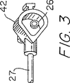
図3は、本発明の第1の実施例の試料室の分解斜視図であり、
図4は、本発明の第1の実施例の試料受け止め部材正面側の斜視図であり、
図5は、本発明の第1の実施例の試料受け止め部材の裏面側の斜視図であり、
図6は、本発明の第1の実施例の管状部材の拡大分解斜視図であり、
図7は、本発明の第1の実施例の遠位組立体の顎が開いた位置にある拡大分解斜視図であり、
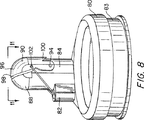
図8は、本発明の第1の実施例の遠位組立体の顎が閉じた位置にある拡大分解斜視図であり、
図9は、図8の底面図であり、
図10は、図7の線10−10に沿った断面図であり、
図11は、図8の線11−11に沿った断面図であり、
図12は、代替の制御部材の形状を例示した第1の実施例の遠位組立体の分解斜視図であり、
図13は、別の代替の制御部材の形状を例示した第1の実施例の遠位組立体の分解斜視図であり、
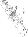
図14は、本発明の内視鏡生検鉗子器具の第2の実施例の分解斜視図であり、
図15は、本発明の第2の実施例の管状部材の拡大分解透視斜視図であり、
図16は、図15の線16−16に沿った拡大断面図であり、
図17は、顎が開いた位置にある本発明の第2の実施例の遠位組立体の拡大分解斜視図であり、
図18は、図17の線18−18に沿った断面図であり、
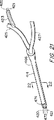
図19は、生検顎が閉じた位置にある本発明の第2の実施例の遠位端の拡大分解斜視図であり、
図20は、図19の線20−20に沿った断面図であり、
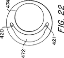
図21は、本発明の第3の実施例の管状部材の拡大分解透視斜視図であり、
図22は、図21の線22−22の拡大断面図であり、及び
図23は、顎が開いた位置にある本発明の第3の実施例の遠位端の拡大分解斜視図である。
好適な実施例の詳細な説明
図1を参照すると、多試料生検鉗子器具10が図示されている。該生検鉗子器具は全体として近位作動ハンドル12と、可撓性の多管腔管状部材14と、引きワイヤ20と、遠位組立体22とを含んでいる。幾つかの結合管が設けられて近位作動ハンドル12を管状部材14、潅注手段及び吸引手段へ結合するのが好適である。詳細には、制御結合管23と、第1及び第2潅注結合管24、25と、第1及び第2吸引結合管26、27とが設けられる。
近位作動ハンドル12は軸30を有し、該軸30は横スロット32及びスプール34を有し、該スプールは前記軸に摺動可能に取り付けられていると共に、当該技術において一般的である如く、前記スロット32を貫通して延びる横棒(図示なし)を有している。作動ハンドル12は試料室42、試料受け止め部材44及びピンチ弁45を備えており、該ピンチ弁45は潅注及び吸引を調整する。図2を参照すると、試料室42は潅注コネクタ46、47を含み、該コネクタ46、47は第1潅注結合管24を第2潅注結合管25に結合している。試料室42は、さらに、第1及び第2吸引コネクタ48、49を含んでおり、該コネクタ48、49は第1吸引結合管26を第2吸引結合管27に結合している。図3乃至図5を参照すると、試料受け止め部材44はハンドル部52、係合部54及びスクリーン56を有し、該係合部54は試料受け止め部材44を試料室42に取り外し可能に係合している。スクリーン56は試料室42を貫通して第1及び第2吸引コネクタ48、49間に延びている。スクリーン56は正面側58及び裏面側60を含んでおり且つ複数の穿孔62を備えており、該穿孔62が切頭円錐形の形状をしているのが好適であり且つ正面側58から裏面側60へ広がっている。第1潅注結合管26及び第1吸引結合管27はピンチ弁45を貫通して延びており、該ピンチ弁45は該結合管26、27を通る流体の流れを制御するように働く。ピンチ弁は付勢されて第1潅注結合管26及び第1吸引結合管27を締め付けて閉鎖する、即ち、該結合管を重ねて潰す。医者の指でピンチ弁45を下方へ押圧するとピンチ弁の付勢に逆らい、第1潅注結合管26及び第1吸引結合管27を通って流体が流れるのが可能となる。
図6及び図7を参照すると共に、本発明の第1の実施例によると、管状部材14は卵形断面を有した多管腔押出成形品であるのが好適である。該管状部材は近位端66、遠位端68、制御導管70、潅注導管72及び吸引導管74を含んでおり、各々が管状部材を貫通して遠位組立体22まで延びている。管状部材の近位端66では制御導管70が制御結合管23に結合され、潅注導管72が第2潅注結合管25に結合され、且つ、吸引導管74が第2吸引管27に結合されている。
図7乃至図9を参照すると、遠位組立体22は実質的に剛性を有する成形カラー80及び移動可能な中空の顎90を含んでいる。カラー80はポリカーボネート、ガラス繊維入りポリカーボネート、硬質等級スチレンまたはその他のプラスチックから成る単一部品から形成されるのが好適であり、一方移動可能な顎90は鋳造金属から形成されるのが好適である。カラーは中央開口部81、円周方向溝83、遠位方向に延びる制御通路82、遠位方向に延びる中空顎取付台84、遠位方向に延びる中空固定顎88及び近位ソケット86を含んでいる。カラー80の中央開口部81の径は内視鏡の外径と同じであり、カラーを内視鏡の遠位端の外側に結合するように設計されている。円周方向溝83はシリコンゴムのソックス(図示なし)の一部を収容しており、該ソックスはカラー80を内視鏡に固定するために使用される。
固定顎88は先の尖っていない刃または縁92を含むのが好適である。移動可能な顎90はピボット94において顎取付台84に旋回可能に取り付けられており、固定顎88に対して旋回可能となる。移動可能な顎90は鋭利な切断刃98、移動可能な顎が固定顎88から旋回して離間する範囲を制限する停止部材100及び下記に説明する如く引きワイヤ20を収容する2つの顎穴102、104を備えているのが好適である。
図9乃至図11を参照すると、近位ソケット86は制御通路82と、取付台84と、固定顎88とに整列しており、且つ、可撓性の管状部材14の遠位端68を収容するように設計されている。管状部材の遠位端68は近位ソケット86に好適には接着剤を使用して取り付けられて、制御通路82が制御導管70に結合され、顎取付台84が潅注導管72に実質的に液密に結合されると共に、固定顎88が吸引導管76に実質的に液密に結合される。
図1、図6、図7及び図10を参照すると、引きワイヤ20の中央部は顎穴102、104を貫通して延びると共に、引きワイヤ20の端部は制御通路82、制御導管70及び制御結合管23を通ってスプール34まで延びている。図12を参照すると、引きワイヤ20aは、代替的に、該ワイヤを折り返し且つ捩り108aを形成して顎穴102a、104aを通る係留ループ106aを形成する。図13を参照すると、更に別の代替例として、2本の引きワイヤ20b、21bを使用することが可能であり、各引きワイヤの遠位端がZ宇状曲がり110b、112bにより顎穴102b、104bに結合され且つ制御通路82bを貫通して延びている。
図1、図7及び図8を参照すると、スプール34が軸30に対して移動すると、引きワイヤ20が管状部材14に対して移動して、その結果、移動可能な顎90を固定顎88に対して移動させ、顎が開いたり(図7)閉じたり(図8)する。図7乃至図11を参照すると、固定顎88及び移動可能な顎90が閉じた位置にある時には、該顎間に実質的に液密な通路が形成される。固定顎88は吸引導管74に結合され且つ移動可能な顎90が潅注導管72を覆って結合されることから、潅注導管と吸引導管とが実質的に液密に結合されるのが可能となる。
使用に当たっては、採取を行うためにカラー80が結合される内視鏡の遠位端が所望の組織に隣接するように操作され、遠位組立体が組織110(図10及び図11)に接触させられる。作動ハンドル12を作動させて顎88、90を閉じて組織試料112を切断する。顎88、90が閉じた位置にある時には、潅注手段及び吸引手段が起動されて、第1近位潅注結合管及び第1近位吸引結合管24、26がピンチ弁を押圧することでピンチ弁45の締付け動作から解放される。これにより潅注液が第1及び第2近位潅注結合管24、26を通り、また、潅注導管72及び中空の顎取付台84を通って生検鉗子器具の遠位端の顎88、90まで流れるのが可能となる。潅注液は顎を通って流れる共に吸引されて生検鉗子器具の近位端へ戻り、顎内に保持されていた試料が水と一緒に吸引されるようにする。図2乃至図6に戻ると、水が吸引導管74を通って試料室42へ吸引されると、試料がスクリーン58上で濾過される。穿孔62の切頭円錐形の形状により穿孔が設けらたスクリーンを通って流れる流体が増大する一方で組織試料がスクリーンを通過するのが防止される。潅注及び吸引手段はピンチ弁45を放すと遮断されて、ピンチ弁が下がり第1近位潅注及び吸引結合管24、26を締め付けて管が重なって潰される。スクリーン58は容易に取り外され、試料受け止め部材44のハンドル部52を把持して試料室42から試料受け止め部材を引っ張ることによって、試料を回収する。試料がスクリーンから回収され、試料受け止め部材を試料室内へ再度挿入して前記手順を継続する。試料の切断及び切断した試料の回収といった全手順は内視鏡多試料生検鉗子器具を身体内の配置部位から取り出さずに実施することが可能なことが更に分かる。同じようにして、無制限に試料を連続して採取することが可能となる。
図14及び図15を参照すると、第2実施例の多試料生検鉗子器具210が図示されている。この器具は近位作動ハンドル212と、可撓性の多管腔管状部材214と、引きワイヤ220と、遠位組立体222とを含んでいる。幾つかの結合管を設けて近位作動ハンドル212を管状部材214及び潅注及び吸引手段へ結合するのが好適である。詳細には、Y字状の制御結合管223、第1及び第2潅注結合管224、225及び第1及び第2吸引結合管226、227が設けられる。
近位作動ハンドル212は実質的には第1実施例と同様である(同様の部品は200を加えた参照番号を付している)。図15、図16及び図17を参照すると、管状部材214は多管腔多層押出成形品であるのが好適であり、最外側層の下に第1金属編組276を含んで管状部材に所望の剛性を追加するのが好適である。所望であれば、第2金属編組277が追加して吸引導管274の回りに設けられ、該吸引導管274に剛性を付与して支持してもよい。管状部材214は近位端266、遠位端268、2つの制御導管270、271、潅注導管272及び吸引導管274を有しており、該導管270、271、272、274の各々は前記管状部材を通って遠位組立体222まで延びている。吸引導管274は実質的に円形の断面を有している。潅注導管272の断面はほぼ腎臓の形状をしており、該潅注導管272は膜275により吸引導管274から分離されている。制御導管270、271は該膜275のそれぞれの端に1つ配置されるのが好適である。
図17乃至図20を参照すると、本発明の第2実施例による遠位組立体222は固定顎281を含んでおり、該固定顎は接着により管状部材の遠位端268へ結合されているのが好適である。固定顎281はプラスチックから形成されるのが好適であり、顎カップ288、一体の中央U字リンク293及び一体の近位傾斜部295、296を含んでいる。顎カップ288は吸引導管274上に配置され、先の尖っていない切断表面または縁292を有しているのが好適である。中央U字リンク293及び近位傾斜部295、296は固定顎281から延びて、潅注導管に当接すると共にその一部を覆っている。移動可能な顎290は金属から形成されるのが好適であり、鋭利な切断刃298を備え、引きワイヤ220を収容する2つの顎穴302、304を形成し、且つ、顎を取り付ける2つのボス312、314を備える。ボス312、314は中央U字リンク293に遊びをもって係合し、ピボットピン294はボス及び中央U字リンクを通って延びている。固定顎281の傾斜部295、296は、移動可能な顎290を開閉する時に該移動可能な顎290を案内して、顎が閉じられると移動可能な顎290と固定顎カップ288との間に実質的に液密の通路を形成する一助となる。引きワイヤ220の中央部は生検鉗子器具の長手方向軸線に対して垂直となっており、顎穴302、304を貫通して延びると共に、引きワイヤの端部は制御導管270、271へ延びている。図15に戻ると、Y字状結合管223は引きワイヤ220の端部を整列させて該引きワイヤを近位作動ハンドルに結合するのを容易にしている。引きワイヤ220はプラスチック等で被覆して管状部材内に食い込むのを抑制するようにすることが可能である。
図18及び図20を参照すると、管状部材の遠位端268が内視鏡の管腔を貫通して生検部位まで挿入されている。顎288、290を閉じた位置に移動して組織試料を切断すると共に、更に、潅注導管及び吸引導管272、274を実質的に液密に結合する。図18及び図20に例示したことから明らかな如く潅注導管272がU字リンク293により遠位端で遮断されている一方で、潅注導管272がU字リンクより実質的に広くて且つ液がU字リンクの回りを流れて吸引導管274へ流れるであろうことが分かる。
図21及び図23を参照すると、第3実施例の多試料生検鉗子が図示されており、該鉗子は第2実施例と類似している(同様の部品には更に200を加えた参照番号を付している)。管状部材414は近位端466、遠位端468、潅注導管472及び吸引導管474を有している。吸引導管474は実質的に円形断面を有する一方、潅注導管472は実質的には三日月形断面を有する。制御結合管423が第2潅注結合管425に結合されている。2本の引きワイヤ420、421が制御導管423を貫通して延び、制御結合管423及び第2潅注結合管425を結合する実質的に液密の弁(図示なし)を通過して、第2潅注結合管425へ進入し、潅注導管472を管状部材の遠位端468まで延びている。吸引結合管427は吸引導管474に結合されている。
図23を参照すると、本発明の第3実施例の遠位組立体422は、管状部材の遠位端468に接合されている固定顎481及び該固定顎481に結合されている移動可能な顎490を含んでいる。固定顎481は顎カップ488、一体中央U字リンク493及び傾斜部495、496を含んでいる。顎カップは管状部材の遠位端に当接すると共に、吸引導管474上に位置決めされ、先の尖っていない切断表面または縁492を有しているのが好適である。中央U字リンク493及び傾斜部495、496は固定顎481から延びて潅注導管474に当接すると共に該導管の一部を覆っている。移動可能な顎490は金属から形成されるのが好適であり、鋭い切断刃498を備え、引きワイヤ420を収容する2つの顎穴402、404を形成し、且つ、顎を取り付ける2つのボス512、514を備えている。ボス512、514は中央U字リンク493に遊びをもって係合すると共に、ピボットピン494はボス及び中央U字リンクを貫通して延びている。傾斜部は、潅注導管の一部を覆うことにより、下記に説明する引きワイヤの入口499、500を形成する。移動可能な顎490は、開いた位置から閉じた位置へ移動する時に、近位傾斜部495、496上に乗る。引きワイヤ420、421はZ字状曲がり506、507により顎穴502、504へ結合され、潅注導管472への入口499、500を通り且つ第2潅注結合管425の一部を貫通し、更に該管に結合されている制御結合管423内へ延びている。入口499、500は十分に小さくて、顎が閉じた位置にあり且つ潅注が潅注導管474を介して遠位組立体へ強制的になされる時にはほんの微量の液体のみしか潅注導管からは流出しない。
多試料内視鏡生検器具の幾つかの実施例を説明例示してきた。本発明の特定の実施例を説明して来たが、本発明は当該技術の範囲と同様に広く且つ明細書から読み取れる範囲となることを意図してなされたものであるから、本発明は斯かる実施例に限定されるものではない。従って、近位作動ハンドルを遠位組立体に結合する特定の方法を幾つかの実施例に関して開示してきたが、近位及び遠位組立体を結合するその他の方法を同様に使用することが可能である。更に、固定顎をプラスチックで形成し且つ移動可能な顎を金属で形成するのが好適であると開示したが、固定、顎及び移動可能な顎の双方をプラスチック、金属または別の材料から形成することも可能である。更に、移動顎を鋳造金属から形成するのが好適であると開示したが、該移動顎を金属から形成する場合には、それに替えて機械加工またはM.I.M.により形成することも可能である。更に、双方の顎を歯を付けずに図示したが、該顎の一方または双方がそれぞれの合わせ面に沿って歯を含むことも可能である。実際、共同所有の米国特許第5,507,296号に開示されている如く、歯を放射状に配列することが可能である。また、1本または2本の引きワイヤを一定の実施例に関して開示したが、各実施例において、1本または2本の引きワイヤを本願に説明した方法で使用することが可能である。更に、固定顎を吸引管に結合し、移動顎を潅注導管に結合して開示したが、固定顎を潅注導管に結合し、移動顎を吸引導管に結合することも可能である。更に、双方の顎を管状部材の遠位端の回りに移動自在にすることも可能である。また、近位作動ハンドルを管状部材に結合することに関して特定の構成を説明してきたが、その他の構成も同様に使用することも可能である。従って、当業者には請求の範囲に記載された精神及び範囲から逸脱することなくその他の修正を本発明に加えることが可能なことは自明のことである。Background of the Invention
1. Field of Invention
The present invention relates generally to an endoscopic surgical instrument, and more particularly, an endoscopic biopsy with means for facilitating removal of a sample without removing the biopsy forceps instrument from the endoscope. The present invention relates to a forceps device.
2. Conventional technology
Endoscopic biopsy methods are typically performed using an endoscope and an endoscopic biopsy forceps device (biopsy forceps, ie, biotopome). An endoscope is a long flexible tube with an optical fiber and a narrow lumen into which a bioptom is inserted. The viptom includes a long flexible coil that has a pair of opposing jaws at the distal end and a manual actuating means at the proximal end. The jaws are opened and closed by operating the operating means. During biopsy tissue collection, the surgeon guides the endoscope to the biopsy site while viewing the biopsy site through the optical fiber of the endoscope. The bioptom is inserted into the narrow lumen of the endoscope and the opposing jaw reaches the biopsy site. While viewing the biopsy site through the endoscope optical fiber, the surgeon positions the jaw around the tissue to be harvested and manipulates the actuation means to close the jaw around the tissue. At this time, the tissue sample is sandwiched between the bioptom jaws and cut and / or torn off from the biopsy site. The surgeon removes the bioptom from the endoscope with the jaws closed and then opens the jaws to collect a biopsy tissue sample.
Biopsy tissue collection procedures often require that several tissue samples be taken from the same or different biopsy sites. Unfortunately, most bioptoms are limited to the collection of a single tissue sample, after which the bioptom must be removed from the endoscope and collected before the bioptom is used again to collect a second tissue sample. Don't be. Several attempts have been made to provide an instrument that allows the collection of several tissue samples before the instrument must be removed and a sample collected. The problem with providing such an instrument is that it requires a very small size to accommodate the narrow lumen of the endoscope and that the instrument is inserted through the lumen of the endoscope. Including that it must be flexible. For this reason, some known multi-sample bioptom instruments have become unusable with endoscopes due to their size and rigidity. These include the “puncture and aspiration type” devices disclosed in US Pat. No. 3,989,033 to Halpern et al. And US Pat. No. 4,522,206 to Whipple et al. It is included. Both of these devices further have a vacuum source with a hollow tube with a punch or punch at the distal end and connected to the proximal end. A tissue sample is cut with a punch and aspirated from a biopsy site through a hollow tube. However, it is generally recognized that dry aspiration (ie, without the use of irrigation fluid) of a tissue sample through a long narrow flexible bioptom is virtually impossible.
Efforts have been made to provide the ability to take multiple samples to instruments that traverse the narrow lumen of an endoscope. These efforts have focused on providing a cylindrical storage space at the distal end of the instrument where several tissue samples can be collected before the instrument is removed from the endoscope. For example, Lifton U.S. Pat. No. 4,651,753 discloses a rigid cylindrical member attached to the distal end of a first flexible tube. The cylindrical member has a lateral opening, and a concentric cylindrical knife blade is slidably mounted within the cylindrical member. A second flexible tube concentric with the first flexible tube is coupled to the knife blade to move the knife blade relative to the lateral opening of the cylindrical member. A third flexible tube having a plunger tip is mounted within the second flexible tube and a vacuum source (syringe) is coupled to the proximal end of the third flexible tube. To take a tissue sample, take the lateral opening of the cylindrical member over the biopsy site, apply a vacuum with a syringe to draw the tissue into the lateral opening, and move the second flexible tube forward Push to move the knife blade across the transverse opening. As a result, the tissue sample is cut and captured in a cylindrical knife in the cylindrical member. Next, the third flexible tube is pushed forward to move the plunger end to press against the tissue sample, and the tissue sample is pushed forward to move into the cylindrical accommodation space at the distal end of the cylindrical member. Enter. Approximately six samples can be accommodated in the cylindrical member. Then remove the instrument from the endoscope. Six samples are collected by removing the distal plug of the cylindrical member and pushing the third flexible tube to expel the sample at its plunger end.
The device of the Lifton patent has several discernible drawbacks. First, it is often difficult to take a tissue sample in the lateral direction of the device. Second, to facilitate the acquisition of the lateral sample, a syringe is used to draw the tissue into the lateral opening. However, the conventional two-step procedure (positioning and cutting) becomes three steps (positioning, suction, and cutting). In addition, the use of a syringe requires additional assistance. Third, the Lifton patent requires the tissue sample to be pushed into the receiving space, adding a fourth step to the biopsy procedure. Thus, the Lifton patent requires considerable effort on the part of the surgeon and assistant, and much of this effort is involved in pushing the tube, which is an anti-intuitive action for classic biopsy collection. Is. A preferred mode of operation of virtually all endoscopic instruments is that the gripping movement at the distal end of the instrument is performed by a similar movement at the proximal end of the instrument. The classic biopsy forceps jaws are closed by pushing a manually actuated member like a syringe.
A more convenient endoscopic multi-sample biopsy device is disclosed in US Pat. No. 5,171,255 to Rydel. The Leidel patent provides a flexible endoscopic instrument with a knife-like sharp cutting cylinder at the distal end. A coaxial anvil is coupled and actuated to the puller wire in the same manner as conventional biopsy forceps. When the anvil is drawn into the cylinder, the tissue located between the anvil and the cylinder is cut and pushed into the accommodating space in the cylinder. Several samples are collected and held in the storage space before the device is removed from the endoscope. While Leidel's device is effective in providing multi-sample instruments where each sample is obtained using a traditional two-step procedure (positioning and cutting), it still limits lateral cutting, which is often a problem It becomes. Traditional biopsy forceps include a jaw that can grasp tissue in front or sideways. Even so, it is difficult to position the jaw around the tissue to be harvested. Lateral sampling is even more difficult.
A more traditional form of multi-sample biopsy forceps is disclosed in commonly owned US Pat. No. 5,542,432, such as Slater et al. Slater et al. Discloses an endoscopic multi-sample biopsy forceps having a jaw assembly that includes a pair of opposed toothed jaw cups each coupled to a base member by an elastic arm. The base member of the jaw assembly is mounted in the cylinder, and moving the jaw assembly and one of the cylinders axially relative to the other pulls the jaw arm into the cylinder, or places the cylinder on the jaw arm. Move the jaw cup to engage with it. The jaw arm effectively forms a containment chamber that extends proximally from the lower jaw cup, and the accumulated biopsy sample is compressed laterally while the jaw is being opened and closed repeatedly. The mandibular cup enhances the movement of the biopsy sample into the containment chamber. Such a device can hold up to four samples before they must be retrieved from the endoscope. However, in some biopsy procedures it may sometimes be desirable to collect more samples. Furthermore, it has been found that it can be somewhat difficult to determine which sample is collected from which biopsy site because the samples in the containment chamber are stuck together.
Crowe, US Pat. No. 5,538,008, collects several samples and transports each sample through a duct through a duct to the proximal end of the instrument for individual collection. A multi-sample bioptom is disclosed. The device includes a set of plastic jaws biased to an open position and connected to the distal end of an elongated tube up to about 7 feet in length. The tube forms a duct. A sleeve extends over the tube and a water flow path is provided between the tube and the sleeve. An opening is provided in the tube to allow the water flow path to merge with the duct at the distal end of the tube. It is disclosed that the sample is cut from the tissue and loaded into the duct by forcibly closing the jaw by returning the tube into the sleeve. The water flow path flows under pressure from the proximal end to the distal end of the flow path, flows into the distal end of the duct through the opening, and is sucked into the proximal end of the duct. It is disclosed that the sample contained in the duct can be transported along with water to the proximal end, allowing the sample to be collected at the proximal end.
Although Crow's device is appealing in writing, in practice its design is infeasible and has drawbacks. For example, if not impossible, it is very difficult to slide an elongate tube up to about 7 feet in length against a sleeve of approximately the same length. It is also difficult to keep the water flow path between the tube and the sleeve unobstructed when the tube and the sleeve are bent and bent through the body. Furthermore, in order for the jaw to cut the tissue sample, the tube and jaw must be pulled into the sleeve, which undesirably pulls the jaw away from the tissue to be harvested.
Summary of the Invention
Accordingly, it is an object of the present invention to provide an endoscopic biopsy forceps instrument that allows a large number of tissue samples to be collected from a patient without removing the forceps from the patient's body. Is to provide an instrument.
Another object of the present invention is an endoscopic biopsy forceps instrument that allows each of several tissue samples to be individually recovered from the forceps without removing the forceps from the patient's body. An endoscopic biopsy forceps instrument is provided.
Still another object of the present invention is to provide an endoscopic biopsy forceps instrument that can collect a tissue sample located distally or laterally with respect to the instrument. It is.
A further object of the present invention is to provide an endoscopic biopsy forceps instrument that irrigates the instrument and aspirates a tissue sample contained within the instrument.
Another object of the present invention is to provide an endoscopic biopsy forceps instrument that includes a reservoir for receiving a sample aspirated through the instrument.
In accordance with the above objectives described in detail below, generally, a proximal actuation handle, a distal forceps assembly, a control member coupled to the proximal actuation handle and the distal forceps assembly, and irrigation An endoscopic biopsy forceps instrument is provided that includes a conduit, a suction conduit, and a flexible multi-lumen tubular member having a control conduit that houses the control member.
According to a preferred embodiment of the present invention, the proximal actuation handle includes a shaft and a spool slidably mounted on the shaft. The actuation handle further includes a proximal irrigation passageway, a sample chamber, a sample receiving member, and a pinch valve that regulates irrigation and aspiration. The proximal irrigation passage is coupled to the irrigation conduit and irrigation coupling tube. The sample chamber is coupled to a suction conduit and a suction coupling tube. The sample receiving member includes a screen inserted into the sample chamber and filters the tissue sample from the aspirated fluid. An irrigation coupling tube and a suction coupling tube extend through the pinch valve, which controls the flow of fluid through the tube. The actuation handle is coupled to the proximal ends of both the flexible tubular member and the control member and is adapted to move the control member relative to the tubular member.
A distal forceps assembly is coupled to the distal end of the tube member, a hollow jaw cup coupled over the distal end of the suction conduit, and a movable coupled pivotally adjacent to the irrigation conduit A hollow jaw. The jaw cup is preferably formed from a hard plastic and has a non-pointed cutting surface, while the movable jaw is a metal jaw with a sharp cutting blade. Is preferred. The movable jaw is further coupled to the control member so that actuating the actuation handle moves the movable jaw relative to the jaw cup, thereby moving the jaw from the open position to the closed position. When the hollow jaw is moved to the closed position, the irrigation conduit and the suction conduit are substantially liquid tightly coupled.
It can be seen that the distal end of such an instrument is brought into contact with the tissue in need of the sample and the actuation handle is actuated to close the jaw and cut the tissue sample. When the jaw is in the closed position, water is irrigated through the irrigation conduit to the jaw at the distal end of the instrument and is drawn from the jaw through the suction conduit to the proximal end of the instrument and cut by the jaw. The sample is aspirated with water. As water is aspirated, the water passes through the sample chamber and the sample is filtered on the screen. The screen can be easily removed to collect the sample. It can further be seen that the entire procedure of cutting and collecting the sample can be performed without removing the endoscopic biopsy forceps instrument from the placement site in the human body.
According to one embodiment of the biopsy forceps instrument, the tubular member has an oval cross-sectional shape and forms a control conduit, an irrigation conduit and a suction conduit. The distal forceps assembly includes a moveable jaw and a substantially rigid molded collar that includes a proximal socket-like coupling means for coupling the tubular member to the collar, a fixed jaw cup, and a distal jaw cup. A position irrigation passage and a control passage. The collar has the same diameter as the endoscope and is connected to the outside of the distal end of the endoscope by a silicone rubber sock. A movable jaw is pivotally attached to the molding collar and is movable relative to the jaw cup. The tubular member is coupled to the socket. The control wire extends through the control conduit and is connected to the two jaw holes through which the control passage is movable.
According to a second embodiment, the biopsy forceps instrument includes a tubular member, which forms a suction conduit having a circular cross section, an irrigation conduit having a kidney shape in cross section, and two control conduits. Yes. The distal forceps assembly includes a fixed jaw and a movable jaw joined to the distal end of the tubular member. The fixed jaw includes a hollow jaw cup, a U-link member and two proximal ramps. The chin cup is disposed on the suction conduit and a U-link and proximal ramp extends from the chin cup onto the irrigation conduit. A movable jaw is coupled to the U-link and guided along the proximal ramp. Two control conduits exit the distal end of the lateral tubular member of the proximal ramp. The central portion of the control member is coupled to the movable jaw, and each end of the control member extends through the control conduit to the proximal end of the biopsy forceps instrument.
According to a third embodiment of the biopsy forceps instrument, the instrument includes a tubular member, which forms a suction conduit having a circular cross section and an irrigation conduit having a crescent cross section. The distal assembly is substantially similar to the second embodiment. The proximal ramp abuts and partially covers the irrigation conduit and forms an entrance to the two irrigation conduits for the control member. The distal end of each control member is coupled to a movable jaw, and the control member extends through the inlet to the irrigation conduit. When the inlet is small enough that the jaw is in a closed position and fluid irrigates the distal assembly through the irrigation conduit, almost all of the fluid flows through the irrigation conduit into the jaw, i.e. irrigation. Only a small amount of fluid irrigated through the conduit exits through the inlet formed by the ramp.
Further objects and advantages of the present invention will become apparent to those skilled in the art from the detailed description taken together with the accompanying drawings.
[Brief description of the drawings]
FIG. 1 is an exploded perspective view of a first embodiment of the endoscopic biopsy forceps instrument of the present invention,
FIG. 2 is an exploded perspective view of the proximal end of the first embodiment of the present invention;
FIG. 3 is an exploded perspective view of the sample chamber of the first embodiment of the present invention,
FIG. 4 is a perspective view of the front side of the sample receiving member of the first embodiment of the present invention,
FIG. 5 is a perspective view of the back side of the sample receiving member of the first embodiment of the present invention,
FIG. 6 is an enlarged exploded perspective view of the tubular member of the first embodiment of the present invention,
FIG. 7 is an enlarged exploded perspective view with the jaws of the distal assembly of the first embodiment of the present invention in the open position;
FIG. 8 is an enlarged exploded perspective view with the jaws of the distal assembly of the first embodiment of the present invention in the closed position;
FIG. 9 is a bottom view of FIG.
10 is a cross-sectional view taken along line 10-10 in FIG.
FIG. 11 is a cross-sectional view taken along line 11-11 in FIG.
FIG. 12 is an exploded perspective view of the distal assembly of the first embodiment illustrating the shape of an alternative control member;
FIG. 13 is an exploded perspective view of the distal assembly of the first embodiment illustrating the shape of another alternative control member;
FIG. 14 is an exploded perspective view of a second embodiment of the endoscopic biopsy forceps instrument of the present invention,
FIG. 15 is an enlarged exploded perspective view of the tubular member of the second embodiment of the present invention,
16 is an enlarged cross-sectional view taken along line 16-16 in FIG.
FIG. 17 is an enlarged exploded perspective view of the distal assembly of the second embodiment of the present invention with the jaws in an open position;
18 is a cross-sectional view taken along line 18-18 of FIG.
FIG. 19 is an enlarged exploded perspective view of the distal end of the second embodiment of the present invention with the biopsy jaws in the closed position;
20 is a cross-sectional view taken along line 20-20 of FIG.
FIG. 21 is an enlarged exploded perspective view of the tubular member of the third embodiment of the present invention,
22 is an enlarged cross-sectional view of line 22-22 of FIG. 21, and
FIG. 23 is an enlarged exploded perspective view of the distal end of the third embodiment of the present invention with the jaws in the open position.
Detailed Description of the Preferred Embodiment
Referring to FIG. 1, a multi-sample
The proximal actuation handle 12 has a
6 and 7, and according to a first embodiment of the present invention, the
With reference to FIGS. 7-9, the
The fixed
Referring to FIGS. 9-11, the
With reference to FIGS. 1, 6, 7 and 10, the central portion of the
With reference to FIGS. 1, 7, and 8, as the
In use, the distal end of the endoscope to which the
Referring to FIGS. 14 and 15, a multi-sample biopsy forceps instrument 210 of the second embodiment is shown. The instrument includes a
The
Referring to FIGS. 17-20, a
18 and 20, the
Referring to FIGS. 21 and 23, a multi-sample biopsy forceps of the third embodiment is illustrated, which is similar to the second embodiment (reference numbers with 200 added to similar parts). Is attached).
Referring to FIG. 23, the
Several examples of multi-sample endoscopic biopsy instruments have been described and illustrated. While specific embodiments of the present invention have been described, the present invention is intended to be as broad and readable as possible from the specification, as is the scope of the technology. It is not limited to such an embodiment. Thus, while a particular method of coupling the proximal actuation handle to the distal assembly has been disclosed with respect to some embodiments, other methods of coupling the proximal and distal assemblies can be used as well. It is. Further, while it has been disclosed that the fixed jaw is preferably made of plastic and the movable jaw is made of metal, both the fixed, jaw and movable jaw are made of plastic, metal or another material. It is also possible. Further, although it has been disclosed that it is preferred to form the moving jaw from cast metal, if the moving jaw is formed from metal, it may be machined or replaced by M.C. I. M.M. It is also possible to form by. Furthermore, although both jaws are shown without teeth, it is possible for one or both of the jaws to include teeth along their mating surfaces. In fact, it is possible to arrange the teeth radially as disclosed in commonly owned US Pat. No. 5,507,296. Also, although one or two puller wires have been disclosed with respect to certain embodiments, in each embodiment, one or two puller wires can be used in the manner described herein. Further, while the fixed jaw is coupled to the suction tube and the moving jaw is coupled to the irrigation conduit, it is also possible to couple the fixed jaw to the irrigation conduit and couple the moving jaw to the suction conduit. It is also possible to make both jaws movable about the distal end of the tubular member. Also, while specific configurations have been described with respect to coupling the proximal actuation handle to the tubular member, other configurations can be used as well. Thus, it will be apparent to one skilled in the art that other modifications may be made to the invention without departing from the spirit and scope as recited in the claims.
Claims (25)
a)潅注導管及び吸引導管を有する可撓性管状部材と、
b)中空の第1の顎及び中空の移動可能な第2の顎を有する遠位組立体であって、前記移動可能な第2の顎が前記第1の顎に対して旋回可能であり且つ前記潅注導管及び前記潅注導管の少なくとも一方に結合され、前記第1の顎が前記潅注導管及び前記吸引導管の前記少なくとも一方の別の方に結合された遠位組立体と、
c)前記遠位組立体に結合されて前記移動可能な第2の顎を前記第1の顎に対して開いた位置から閉じた位置へ移動させて患者から組織試料を得るようにされた近位作動装置とを備え、前記移動可能な第2の顎及び前記第1の顎は、前記移動可能な第2の顎及び前記第1の顎が前記閉じた位置にある時には、前記移動可能な第2の顎及び前記第1の顎が前記潅注導管と前記吸引導管との間に実質的に閉じた流体通路を形成して、前記吸引導管が前記潅注導管により供給された潅注液で前記遠位組立体から前記組織試料を回収することができるようにされている、生検鉗子器具。In a biopsy forceps instrument that collects a tissue sample from a patient using an endoscope,
a) a flexible tubular member having an irrigation conduit and a suction conduit;
b) a distal assembly having a hollow first jaw and a hollow movable second jaw, wherein the movable second jaw is pivotable relative to the first jaw; A distal assembly coupled to at least one of the irrigation conduit and the irrigation conduit, wherein the first jaw is coupled to the other of the irrigation conduit and the suction conduit;
c) a proximity coupled to the distal assembly to move the movable second jaw relative to the first jaw from an open position to a closed position to obtain a tissue sample from a patient; A position actuating device, wherein the movable second jaw and the first jaw are movable when the movable second jaw and the first jaw are in the closed position. The second jaw and the first jaw form a substantially closed fluid passageway between the irrigation conduit and the suction conduit, and the suction conduit is irrigated with irrigation fluid supplied by the irrigation conduit. A biopsy forceps instrument adapted to allow the tissue sample to be retrieved from a positioning assembly.
Applications Claiming Priority (3)
| Application Number | Priority Date | Filing Date | Title |
|---|---|---|---|
| US08/756,260 US5897507A (en) | 1996-11-25 | 1996-11-25 | Biopsy forceps instrument having irrigation and aspiration capabilities |
| US08/756,260 | 1996-11-25 | ||
| PCT/US1997/021512 WO1998025523A1 (en) | 1996-11-25 | 1997-11-24 | Biopsy forceps instrument having irrigation and aspiration capabilities |
Publications (3)
| Publication Number | Publication Date |
|---|---|
| JP2001508674A JP2001508674A (en) | 2001-07-03 |
| JP2001508674A5 JP2001508674A5 (en) | 2005-08-11 |
| JP3964466B2 true JP3964466B2 (en) | 2007-08-22 |
Family
ID=25042699
Family Applications (1)
| Application Number | Title | Priority Date | Filing Date |
|---|---|---|---|
| JP52670998A Expired - Fee Related JP3964466B2 (en) | 1996-11-25 | 1997-11-24 | Biopsy forceps instrument with irrigation and suction capabilities |
Country Status (10)
| Country | Link |
|---|---|
| US (2) | US5897507A (en) |
| EP (1) | EP0971633B1 (en) |
| JP (1) | JP3964466B2 (en) |
| AU (1) | AU735654B2 (en) |
| BR (1) | BR9714360A (en) |
| CA (1) | CA2272871C (en) |
| DE (1) | DE69737213T2 (en) |
| ES (1) | ES2279553T3 (en) |
| IL (1) | IL130100A0 (en) |
| WO (1) | WO1998025523A1 (en) |
Families Citing this family (101)
| Publication number | Priority date | Publication date | Assignee | Title |
|---|---|---|---|---|
| US6331165B1 (en) * | 1996-11-25 | 2001-12-18 | Scimed Life Systems, Inc. | Biopsy instrument having irrigation and aspiration capabilities |
| US6142956A (en) * | 1996-11-25 | 2000-11-07 | Symbiosis Corporation | Proximal actuation handle for a biopsy forceps instrument having irrigation and aspiration capabilities |
| US7637948B2 (en) | 1997-10-10 | 2009-12-29 | Senorx, Inc. | Tissue marking implant |
| US8668737B2 (en) | 1997-10-10 | 2014-03-11 | Senorx, Inc. | Tissue marking implant |
| US6273860B1 (en) * | 1998-05-04 | 2001-08-14 | Lsvp International, Inc. | Biopsy apparatus |
| US6273882B1 (en) | 1998-06-18 | 2001-08-14 | Scimed Life Systems | Snap handle assembly for an endoscopic instrument |
| US7983734B2 (en) | 2003-05-23 | 2011-07-19 | Senorx, Inc. | Fibrous marker and intracorporeal delivery thereof |
| US9820824B2 (en) | 1999-02-02 | 2017-11-21 | Senorx, Inc. | Deployment of polysaccharide markers for treating a site within a patent |
| US8361082B2 (en) | 1999-02-02 | 2013-01-29 | Senorx, Inc. | Marker delivery device with releasable plug |
| US20090216118A1 (en) | 2007-07-26 | 2009-08-27 | Senorx, Inc. | Polysaccharide markers |
| US6725083B1 (en) | 1999-02-02 | 2004-04-20 | Senorx, Inc. | Tissue site markers for in VIVO imaging |
| US8498693B2 (en) | 1999-02-02 | 2013-07-30 | Senorx, Inc. | Intracorporeal marker and marker delivery device |
| US7651505B2 (en) | 2002-06-17 | 2010-01-26 | Senorx, Inc. | Plugged tip delivery for marker placement |
| US6862470B2 (en) | 1999-02-02 | 2005-03-01 | Senorx, Inc. | Cavity-filling biopsy site markers |
| US6575991B1 (en) * | 1999-06-17 | 2003-06-10 | Inrad, Inc. | Apparatus for the percutaneous marking of a lesion |
| US6537205B1 (en) * | 1999-10-14 | 2003-03-25 | Scimed Life Systems, Inc. | Endoscopic instrument system having reduced backlash control wire action |
| ITCE990004A1 (en) * | 1999-10-25 | 2000-01-25 | Mario Immacolato Paternuosto | VALVE FOR BIOPSY FORCEPS IN DIGESTIVE ENDOSCOPY |
| US6358262B1 (en) | 1999-11-05 | 2002-03-19 | Alcon Universal Ltd. | Lamellar dissecting instrument |
| US6596000B2 (en) | 1999-11-05 | 2003-07-22 | Alcon Universal Ltd. | Instrument for positioning an intracorneal optical lens |
| US8016855B2 (en) * | 2002-01-08 | 2011-09-13 | Tyco Healthcare Group Lp | Surgical device |
| GB0017728D0 (en) * | 2000-07-19 | 2000-09-06 | South Manchester University Ho | Vessel dilator |
| US6921361B2 (en) * | 2000-07-24 | 2005-07-26 | Olympus Corporation | Endoscopic instrument for forming an artificial valve |
| US6488695B1 (en) * | 2000-08-17 | 2002-12-03 | Alcon, Inc. | Ophthalmologic surgical probe |
| US6572578B1 (en) | 2000-08-25 | 2003-06-03 | Patrick A. Blanchard | Fluid-jet catheter and its application to flexible endoscopy |
| CA2659484C (en) | 2000-11-20 | 2013-01-08 | Senorx, Inc. | Tissue site markers for in vivo imaging |
| US6551315B2 (en) * | 2000-12-06 | 2003-04-22 | Syntheon, Llc | Methods and apparatus for the treatment of gastric ulcers |
| US7727246B2 (en) | 2000-12-06 | 2010-06-01 | Ethicon Endo-Surgery, Inc. | Methods for endoluminal treatment |
| US20020068945A1 (en) * | 2000-12-06 | 2002-06-06 | Robert Sixto | Surgical clips particularly useful in the endoluminal treatment of gastroesophageal reflux disease (GERD) |
| US8062314B2 (en) * | 2000-12-06 | 2011-11-22 | Ethicon Endo-Surgery, Inc. | Methods for the endoluminal treatment of gastroesophageal reflux disease (GERD) |
| US7232445B2 (en) * | 2000-12-06 | 2007-06-19 | Id, Llc | Apparatus for the endoluminal treatment of gastroesophageal reflux disease (GERD) |
| US20020138086A1 (en) * | 2000-12-06 | 2002-09-26 | Robert Sixto | Surgical clips particularly useful in the endoluminal treatment of gastroesophageal reflux disease (GERD) |
| US6716226B2 (en) | 2001-06-25 | 2004-04-06 | Inscope Development, Llc | Surgical clip |
| JP4261814B2 (en) | 2001-04-04 | 2009-04-30 | オリンパス株式会社 | Tissue puncture system |
| JP4493258B2 (en) * | 2001-04-04 | 2010-06-30 | オリンパス株式会社 | Tissue puncture device |
| US7341564B2 (en) * | 2001-05-03 | 2008-03-11 | Boston Scientific Scimed, Inc. | Biopsy forceps device with transparent outer sheath |
| US6808491B2 (en) | 2001-05-21 | 2004-10-26 | Syntheon, Llc | Methods and apparatus for on-endoscope instruments having end effectors and combinations of on-endoscope and through-endoscope instruments |
| US20050277956A1 (en) * | 2004-06-14 | 2005-12-15 | Francese Jose L | Clip storage for endoscopic clip applier |
| US7175594B2 (en) * | 2002-01-22 | 2007-02-13 | Foulkes Richard B | Ophthalmic sulcus speculum |
| US20060036158A1 (en) | 2003-11-17 | 2006-02-16 | Inrad, Inc. | Self-contained, self-piercing, side-expelling marking apparatus |
| US20040193189A1 (en) * | 2003-03-25 | 2004-09-30 | Kortenbach Juergen A. | Passive surgical clip |
| US7105000B2 (en) * | 2003-03-25 | 2006-09-12 | Ethicon Endo-Surgery, Inc. | Surgical jaw assembly with increased mechanical advantage |
| US20040193188A1 (en) * | 2003-03-25 | 2004-09-30 | Inscope Development, Llc | Laminated surgical clip |
| US7578786B2 (en) | 2003-04-01 | 2009-08-25 | Boston Scientific Scimed, Inc. | Video endoscope |
| US20050245789A1 (en) * | 2003-04-01 | 2005-11-03 | Boston Scientific Scimed, Inc. | Fluid manifold for endoscope system |
| US7591783B2 (en) | 2003-04-01 | 2009-09-22 | Boston Scientific Scimed, Inc. | Articulation joint for video endoscope |
| US20040199052A1 (en) | 2003-04-01 | 2004-10-07 | Scimed Life Systems, Inc. | Endoscopic imaging system |
| US8118732B2 (en) | 2003-04-01 | 2012-02-21 | Boston Scientific Scimed, Inc. | Force feedback control system for video endoscope |
| US7877133B2 (en) | 2003-05-23 | 2011-01-25 | Senorx, Inc. | Marker or filler forming fluid |
| US7588545B2 (en) * | 2003-09-10 | 2009-09-15 | Boston Scientific Scimed, Inc. | Forceps and collection assembly with accompanying mechanisms and related methods of use |
| US20050273002A1 (en) | 2004-06-04 | 2005-12-08 | Goosen Ryan L | Multi-mode imaging marker |
| US7942896B2 (en) | 2003-11-25 | 2011-05-17 | Scimed Life Systems, Inc. | Forceps and collection assembly and related methods of use and manufacture |
| US20050166731A1 (en) * | 2004-01-29 | 2005-08-04 | Jones William R. | Rotary saw table and method for adapting various rotary saws to rotary saw table |
| WO2006039267A2 (en) | 2004-09-30 | 2006-04-13 | Boston Scientific Scimed, Inc. | Multi-functional endoscopic system for use in electrosurgical applications |
| US7241263B2 (en) | 2004-09-30 | 2007-07-10 | Scimed Life Systems, Inc. | Selectively rotatable shaft coupler |
| AU2005291952A1 (en) | 2004-09-30 | 2006-04-13 | Boston Scientific Limited | Adapter for use with digital imaging medical device |
| EP1799096A2 (en) | 2004-09-30 | 2007-06-27 | Boston Scientific Scimed, Inc. | System and method of obstruction removal |
| US7479106B2 (en) | 2004-09-30 | 2009-01-20 | Boston Scientific Scimed, Inc. | Automated control of irrigation and aspiration in a single-use endoscope |
| US8083671B2 (en) | 2004-09-30 | 2011-12-27 | Boston Scientific Scimed, Inc. | Fluid delivery system for use with an endoscope |
| EP1806090A4 (en) * | 2004-10-05 | 2010-03-03 | Olympus Corp | Endoscope system, bio-specimen storage container, bio-specimen sampling method, and bio-specimen treating method |
| US7905857B2 (en) | 2005-07-11 | 2011-03-15 | Covidien Ag | Needle assembly including obturator with safety reset |
| US7850650B2 (en) | 2005-07-11 | 2010-12-14 | Covidien Ag | Needle safety shield with reset |
| US7828773B2 (en) | 2005-07-11 | 2010-11-09 | Covidien Ag | Safety reset key and needle assembly |
| US8419656B2 (en) * | 2004-11-22 | 2013-04-16 | Bard Peripheral Vascular, Inc. | Post decompression marker introducer system |
| US7546089B2 (en) * | 2004-12-23 | 2009-06-09 | Triquint Semiconductor, Inc. | Switchable directional coupler for use with RF devices |
| ATE440552T1 (en) * | 2005-01-20 | 2009-09-15 | Wilson Cook Medical Inc | BIOPSY FORCEPS |
| US10357328B2 (en) | 2005-04-20 | 2019-07-23 | Bard Peripheral Vascular, Inc. and Bard Shannon Limited | Marking device with retractable cannula |
| US8097003B2 (en) | 2005-05-13 | 2012-01-17 | Boston Scientific Scimed, Inc. | Endoscopic apparatus with integrated variceal ligation device |
| US7846107B2 (en) | 2005-05-13 | 2010-12-07 | Boston Scientific Scimed, Inc. | Endoscopic apparatus with integrated multiple biopsy device |
| US7762960B2 (en) | 2005-05-13 | 2010-07-27 | Boston Scientific Scimed, Inc. | Biopsy forceps assemblies |
| US20060276747A1 (en) | 2005-06-06 | 2006-12-07 | Sherwood Services Ag | Needle assembly with removable depth stop |
| US7731692B2 (en) | 2005-07-11 | 2010-06-08 | Covidien Ag | Device for shielding a sharp tip of a cannula and method of using the same |
| US8052597B2 (en) | 2005-08-30 | 2011-11-08 | Boston Scientific Scimed, Inc. | Method for forming an endoscope articulation joint |
| CA2562580C (en) | 2005-10-07 | 2014-04-29 | Inrad, Inc. | Drug-eluting tissue marker |
| US7654735B2 (en) | 2005-11-03 | 2010-02-02 | Covidien Ag | Electronic thermometer |
| US7967759B2 (en) | 2006-01-19 | 2011-06-28 | Boston Scientific Scimed, Inc. | Endoscopic system with integrated patient respiratory status indicator |
| US7918783B2 (en) * | 2006-03-22 | 2011-04-05 | Boston Scientific Scimed, Inc. | Endoscope working channel with multiple functionality |
| US8888684B2 (en) | 2006-03-27 | 2014-11-18 | Boston Scientific Scimed, Inc. | Medical devices with local drug delivery capabilities |
| US7857827B2 (en) * | 2006-04-14 | 2010-12-28 | Ethicon Endo-Surgery, Inc. | Endoscopic device |
| US7998167B2 (en) * | 2006-04-14 | 2011-08-16 | Ethicon Endo-Surgery, Inc. | End effector and method of manufacture |
| US20070244511A1 (en) * | 2006-04-14 | 2007-10-18 | Ethicon Endo-Surgery, Inc. | Endoscopic device and method of assembly |
| US8202265B2 (en) | 2006-04-20 | 2012-06-19 | Boston Scientific Scimed, Inc. | Multiple lumen assembly for use in endoscopes or other medical devices |
| US7955255B2 (en) | 2006-04-20 | 2011-06-07 | Boston Scientific Scimed, Inc. | Imaging assembly with transparent distal cap |
| CN101496283A (en) * | 2006-07-27 | 2009-07-29 | 松下电器产业株式会社 | Semiconductor integrated circuit, program converting apparatus and mapping apparatus |
| US8064987B2 (en) * | 2006-10-23 | 2011-11-22 | C. R. Bard, Inc. | Breast marker |
| US9579077B2 (en) | 2006-12-12 | 2017-02-28 | C.R. Bard, Inc. | Multiple imaging mode tissue marker |
| EP2101670B1 (en) | 2006-12-18 | 2013-07-31 | C.R.Bard, Inc. | Biopsy marker with in situ-generated imaging properties |
| CA2702352C (en) * | 2007-10-12 | 2015-06-02 | Med-El Elektromedizinische Geraete Gmbh | Implant magnet insertion and removal tools |
| US8357104B2 (en) * | 2007-11-01 | 2013-01-22 | Coviden Lp | Active stylet safety shield |
| US8311610B2 (en) | 2008-01-31 | 2012-11-13 | C. R. Bard, Inc. | Biopsy tissue marker |
| US9327061B2 (en) | 2008-09-23 | 2016-05-03 | Senorx, Inc. | Porous bioabsorbable implant |
| US9095328B2 (en) | 2008-12-12 | 2015-08-04 | Boston Scientific Scimed, Inc. | Endoscopes having multiple lumens for tissue acquisition and removal and related methods of use |
| EP3005971B1 (en) | 2008-12-30 | 2023-04-26 | C. R. Bard, Inc. | Marker delivery device for tissue marker placement |
| US8382791B2 (en) * | 2009-08-28 | 2013-02-26 | The Penn State Research Foundation | Surgical tool |
| US20110237975A1 (en) * | 2010-03-24 | 2011-09-29 | United States Endoscopy Group, Inc. | Multiple biopsy device |
| USD715442S1 (en) | 2013-09-24 | 2014-10-14 | C. R. Bard, Inc. | Tissue marker for intracorporeal site identification |
| USD716451S1 (en) | 2013-09-24 | 2014-10-28 | C. R. Bard, Inc. | Tissue marker for intracorporeal site identification |
| USD715942S1 (en) | 2013-09-24 | 2014-10-21 | C. R. Bard, Inc. | Tissue marker for intracorporeal site identification |
| USD716450S1 (en) | 2013-09-24 | 2014-10-28 | C. R. Bard, Inc. | Tissue marker for intracorporeal site identification |
| CN103750846A (en) * | 2014-01-24 | 2014-04-30 | 塔里木大学 | Cobitidae fish blood fixation method |
| EP3154630B1 (en) | 2014-06-16 | 2020-12-30 | MED-EL Elektromedizinische Geräte GmbH | Implant magnet insertion and removal tools |
| CN105749362B (en) * | 2016-02-14 | 2018-05-15 | 山东省肿瘤医院 | One kind separation attracts integrated device |
Family Cites Families (113)
| Publication number | Priority date | Publication date | Assignee | Title |
|---|---|---|---|---|
| US33258A (en) * | 1861-09-10 | Improvement in gas-burners | ||
| US2708437A (en) * | 1952-03-31 | 1955-05-17 | Elizabeth Painter Hutchins | Surgical instrument |
| FR1311292A (en) * | 1961-10-23 | 1962-12-07 | Levallois Optique Et Prec | Advanced biopsy probe and combination of such probe with an endoscope |
| US3289669A (en) * | 1964-02-25 | 1966-12-06 | Donald J Dwyer | Biopsy capsule arrangement |
| US3401684A (en) * | 1965-12-16 | 1968-09-17 | Weck & Co Edward | Biopsy capsules |
| US3590808A (en) * | 1968-09-04 | 1971-07-06 | Us Catheter & Instr Corp | Biopsy tool |
| US3732858A (en) * | 1968-09-16 | 1973-05-15 | Surgical Design Corp | Apparatus for removing blood clots, cataracts and other objects from the eye |
| US3898049A (en) * | 1971-10-05 | 1975-08-05 | Texaco Inc | Hydrogenation reactors with improved flow distribution |
| US3989049A (en) * | 1973-07-30 | 1976-11-02 | In Bae Yoon | Method of applying an elastic ring to an anatomical tubular structure |
| AR196829A1 (en) * | 1973-12-06 | 1974-02-19 | Halpern D | SURGICAL INSTRUMENT FOR BIOPSIES |
| US3980086A (en) * | 1974-02-28 | 1976-09-14 | Bio-Medicus, Inc. | Fluid conveying surgical instrument |
| US3964468A (en) * | 1975-05-30 | 1976-06-22 | The Board Of Trustees Of Leland Stanford Junior University | Bioptome |
| US3992565A (en) * | 1975-07-07 | 1976-11-16 | Belden Corporation | Composite welding cable having gas ducts and switch wires therein |
| US4014333A (en) * | 1975-09-22 | 1977-03-29 | Mcintyre David J | Instrument for aspirating and irrigating during ophthalmic surgery |
| GB2022421B (en) * | 1978-06-08 | 1982-09-15 | Wolf Gmbh Richard | Devices for obtaining tissure samples |
| US4200111A (en) * | 1978-09-21 | 1980-04-29 | Harris Arthur M | Specimen removal instrument |
| JPS5836538A (en) | 1981-08-26 | 1983-03-03 | オリンパス光学工業株式会社 | Forceps for endoscope |
| US4445517A (en) * | 1981-09-28 | 1984-05-01 | Feild James Rodney | Suction dissector |
| US4519385A (en) * | 1982-12-01 | 1985-05-28 | Snyder Laboratories, Inc. | Lavage handpiece |
| US4522206A (en) * | 1983-01-26 | 1985-06-11 | Dyonics, Inc. | Surgical instrument |
| US4662371A (en) * | 1983-01-26 | 1987-05-05 | Whipple Terry L | Surgical instrument |
| US4617013A (en) * | 1983-03-14 | 1986-10-14 | Timron Instruments, Incorporated | Method and apparatus for surgical irrigation, aspiration and illumination |
| US4919152A (en) * | 1987-03-02 | 1990-04-24 | Ralph Ger | Method of closing the opening of a hernial sac |
| US4712545A (en) * | 1984-04-05 | 1987-12-15 | Acufex Microsurgical, Inc. | Surgical instrument |
| DE3581665D1 (en) * | 1984-05-18 | 1991-03-14 | Harald Maslanka | SURGICAL GRIPPER INSTRUMENT. |
| USRE33258E (en) | 1984-07-23 | 1990-07-10 | Surgical Dynamics Inc. | Irrigating, cutting and aspirating system for percutaneous surgery |
| JPS637218Y2 (en) * | 1984-09-28 | 1988-03-01 | ||
| US4651753A (en) * | 1984-10-12 | 1987-03-24 | Jayco Pharmaceuticals | Endoscopic multiple biopsy instrument |
| DD233302A1 (en) * | 1984-12-28 | 1986-02-26 | Univ Berlin Humboldt | SAFETY BIOPSY FORCEPS |
| US4644951A (en) * | 1985-09-16 | 1987-02-24 | Concept, Inc. | Vacuum sleeve for a surgical appliance |
| US4763668A (en) * | 1985-10-28 | 1988-08-16 | Mill Rose Laboratories | Partible forceps instrument for endoscopy |
| US4759349A (en) * | 1986-02-24 | 1988-07-26 | Vitalmetrics, Inc. | Surgical instrument having a heat sink for irrigation, aspiration, and illumination |
| US4693257A (en) * | 1986-05-12 | 1987-09-15 | Markham Charles W | Needle aspiration biopsy device with enclosed fluid supply |
| US4950278A (en) * | 1986-08-06 | 1990-08-21 | Sachse Hans E | Endoscope for removal of tissue |
| DE3630203A1 (en) * | 1986-09-04 | 1988-03-17 | Wisap Gmbh | TISSUE PUNCHING |
| US4681123A (en) * | 1986-10-31 | 1987-07-21 | Valtchev Konstantin L | Chorion biopsy instrument |
| JPS63164935A (en) * | 1986-12-27 | 1988-07-08 | 株式会社東芝 | Suction apparatus of endoscope |
| DE8702446U1 (en) * | 1987-02-18 | 1987-10-08 | Kothe, Lutz, 7760 Radolfzell, De | |
| US4776840A (en) * | 1987-09-28 | 1988-10-11 | Alteron, Inc. | Hand-held medical evacuator and irrigation device |
| DE3736150A1 (en) * | 1987-10-26 | 1989-05-03 | Wolf Gmbh Richard | PLIERS, ESPECIALLY HOOK PUNCH |
| IT1211530B (en) * | 1987-11-16 | 1989-11-03 | Consiglio Nazionale Ricerche | AREA OF THE POINT OF ORIGIN OF ARITCATERERE FOR ENDOCARDIC BIOPSY AND MY VENTRICULARS THAT CAN BE USED ALSO FOR THE INDIVIDUAL |
| FR2625428A1 (en) * | 1988-01-05 | 1989-07-07 | Sinergy Sa | MULTIFUNCTIONAL OPERATIVE COELIOSCOPY DEVICE FOR PERFORMING DIFFERENT OPERATIVE GESTURES WITH INTRODUCTION OF INSTRUMENTS |
| US4971067A (en) * | 1988-05-05 | 1990-11-20 | Lee Bolduc | Biopsy instrument with a disposable cutting blade |
| DE8809501U1 (en) * | 1988-07-26 | 1988-11-24 | Schad, Karl, 7201 Kolbingen, De | |
| US4986825A (en) * | 1988-10-11 | 1991-01-22 | Concept, Inc. | Surgical cutting instrument |
| US4966162A (en) * | 1989-01-25 | 1990-10-30 | Wang Ko P | Flexible encoscope assembly |
| US5172700A (en) * | 1989-01-31 | 1992-12-22 | C. R. Bard, Inc. | Disposable biopsy forceps |
| DE3918720A1 (en) * | 1989-06-08 | 1990-12-20 | Wolf Gmbh Richard | RETROGRAD CUTTING HOOK PUNCH |
| US5106364A (en) * | 1989-07-07 | 1992-04-21 | Kabushiki Kaisha Topcon | Surgical cutter |
| CA1337714C (en) * | 1989-07-31 | 1995-12-12 | Karen E. Kullas | Irrigation system for use with endoscopic procedure |
| US5632746A (en) | 1989-08-16 | 1997-05-27 | Medtronic, Inc. | Device or apparatus for manipulating matter |
| US5085658A (en) * | 1989-09-05 | 1992-02-04 | Percutaneous Technologies | Neurosurgical pathological tissue removing device |
| US5505210A (en) * | 1989-11-06 | 1996-04-09 | Mectra Labs, Inc. | Lavage with tissue cutting cannula |
| US5312400A (en) * | 1992-10-09 | 1994-05-17 | Symbiosis Corporation | Cautery probes for endoscopic electrosurgical suction-irrigation instrument |
| US5195958A (en) * | 1990-05-25 | 1993-03-23 | Phillips Edward H | Tool for laparoscopic surgery |
| US5152780A (en) * | 1990-05-31 | 1992-10-06 | Tnco, Inc. | Micro-instrument |
| US5219357A (en) * | 1990-05-31 | 1993-06-15 | Tnco, Inc. | Micro-instrument |
| JPH04135554A (en) * | 1990-09-26 | 1992-05-11 | Olympus Optical Co Ltd | Treating implement |
| WO1992007516A1 (en) * | 1990-11-05 | 1992-05-14 | Koscher & Würtz Gmbh | Surgical instrument |
| US5171255A (en) * | 1990-11-21 | 1992-12-15 | Everest Medical Corporation | Biopsy device |
| US5082000A (en) * | 1990-11-29 | 1992-01-21 | Applied Medical Technology, Inc. | Biopsy forceps with calde controlled jaws |
| US5209747A (en) * | 1990-12-13 | 1993-05-11 | Knoepfler Dennis J | Adjustable angle medical forceps |
| US5147292A (en) * | 1991-02-05 | 1992-09-15 | C. R. Bard, Inc. | Control handle with locking means for surgical irrigation |
| US5125910A (en) * | 1991-02-19 | 1992-06-30 | Dexide, Inc. | Surgical endoscopic suction/irrigation cannula assembly |
| US5300087A (en) * | 1991-03-22 | 1994-04-05 | Knoepfler Dennis J | Multiple purpose forceps |
| US5217460A (en) * | 1991-03-22 | 1993-06-08 | Knoepfler Dennis J | Multiple purpose forceps |
| US5195959A (en) * | 1991-05-31 | 1993-03-23 | Paul C. Smith | Electrosurgical device with suction and irrigation |
| DE69218688T2 (en) * | 1991-07-29 | 1997-07-10 | Smith & Nephew Richards Inc | Pliers |
| US5286255A (en) * | 1991-07-29 | 1994-02-15 | Linvatec Corporation | Surgical forceps |
| US5197968A (en) * | 1991-08-14 | 1993-03-30 | Mectra Labs, Inc. | Disposable tissue retrieval assembly |
| US5160343A (en) * | 1991-09-09 | 1992-11-03 | Dexide, Inc. | Surgical instruments handle and forceps assembly |
| US5285795A (en) * | 1991-09-12 | 1994-02-15 | Surgical Dynamics, Inc. | Percutaneous discectomy system having a bendable discectomy probe and a steerable cannula |
| AU656628B2 (en) * | 1991-10-18 | 1995-02-09 | United States Surgical Corporation | Endoscopic surgical instrument for aspiration and irrigation |
| US5551448A (en) * | 1991-10-18 | 1996-09-03 | United States Surgical Corporation | Endoscopic surgical instrument for aspiration and irrigation |
| US5197963A (en) * | 1991-12-02 | 1993-03-30 | Everest Medical Corporation | Electrosurgical instrument with extendable sheath for irrigation and aspiration |
| US5433725A (en) | 1991-12-13 | 1995-07-18 | Unisurge, Inc. | Hand-held surgical device and tools for use therewith, assembly and method |
| US5244459A (en) * | 1992-01-28 | 1993-09-14 | Hill Raymond R | Suction irrigator endoscope |
| US5645075A (en) * | 1992-02-18 | 1997-07-08 | Symbiosis Corporation | Jaw assembly for an endoscopic instrument |
| US5636639A (en) * | 1992-02-18 | 1997-06-10 | Symbiosis Corporation | Endoscopic multiple sample bioptome with enhanced biting action |
| US5542432A (en) * | 1992-02-18 | 1996-08-06 | Symbiosis Corporation | Endoscopic multiple sample bioptome |
| US5195533A (en) * | 1992-05-08 | 1993-03-23 | Boston Scientific Corporation | Biopsy needle instrument for storing multiple specimens |
| US5186714A (en) * | 1992-05-18 | 1993-02-16 | Yab Revo-Tech Inc. | Multifunctional surgical instrument |
| US5238002A (en) * | 1992-06-08 | 1993-08-24 | C. R. Bard, Inc. | Disposable biopsy forceps |
| US5230704A (en) * | 1992-06-26 | 1993-07-27 | Biomedical Dynamics Corporation | Suction/irrigation instrument having reusable handle with disposable fluid path |
| US5251641A (en) * | 1992-07-29 | 1993-10-12 | Hgg Laser Fare, Inc. | Biopsy needle |
| US5411514A (en) * | 1992-09-30 | 1995-05-02 | Linvatec Corporation | Bendable variable angle rotating shaver |
| US5312327A (en) * | 1992-10-09 | 1994-05-17 | Symbiosis Corporation | Cautery override safety systems endoscopic electrosurgical suction-irrigation instrument |
| US5314406A (en) * | 1992-10-09 | 1994-05-24 | Symbiosis Corporation | Endoscopic electrosurgical suction-irrigation instrument |
| US5683359A (en) * | 1992-11-18 | 1997-11-04 | Symbiosis Corporation | Arthroscopic surgical instruments having suction capability |
| WO1994015533A2 (en) * | 1993-01-18 | 1994-07-21 | John Crowe | Endoscope forceps |
| US5593416A (en) * | 1993-01-26 | 1997-01-14 | Donahue; John R. | Method of using flexible surgical instrument |
| US5575753A (en) * | 1993-03-05 | 1996-11-19 | Olympus Optical Co., Ltd. | Endoscopic apparatus using a covered type endoscope fitted in an endoscope cover |
| US5344428A (en) * | 1993-03-05 | 1994-09-06 | Auburn International, Inc. | Miniature surgical instrument |
| US5325866A (en) * | 1993-04-20 | 1994-07-05 | Jacek Krzyzanowski | Flexible biopsy forceps |
| US5419774A (en) | 1993-07-13 | 1995-05-30 | Scimed Life Systems, Inc. | Thrombus extraction device |
| US5336238A (en) * | 1993-07-19 | 1994-08-09 | Birtcher Medical Systems, Inc. | Surgical instrument capable of disassembly |
| DE4328855C1 (en) | 1993-08-27 | 1995-01-12 | Beckmann Hans Juergen Dr | Spoon-shaped forceps instrument for minimally invasive surgery |
| US5601585A (en) * | 1994-02-08 | 1997-02-11 | Boston Scientific Corporation | Multi-motion side-cutting biopsy sampling device |
| US5573008A (en) * | 1993-10-29 | 1996-11-12 | Boston Scientific Corporation | Multiple biopsy sampling coring device |
| US5456689A (en) * | 1993-10-13 | 1995-10-10 | Arnold J. Kresch | Method and device for tissue resection |
| US5638827A (en) * | 1994-02-01 | 1997-06-17 | Symbiosis Corporation | Super-elastic flexible jaws assembly for an endoscopic multiple sample bioptome |
| US5471992A (en) * | 1994-02-08 | 1995-12-05 | Boston Scientific Corporation | Multi-motion cutter multiple biopsy sampling device |
| US5417709A (en) * | 1994-04-12 | 1995-05-23 | Symbiosis Corporation | Endoscopic instrument with end effectors forming suction and/or irrigation lumens |
| US5595185A (en) * | 1994-08-11 | 1997-01-21 | N.M.B. Medical Applications Ltd. | Single puncture multi-biopsy gun |
| US5527332A (en) * | 1994-11-02 | 1996-06-18 | Mectra Labs, Inc. | Tissue cutter for surgery |
| US5562102A (en) * | 1994-11-21 | 1996-10-08 | Taylor; Thomas V. | Multiple biopsy device |
| US5575293A (en) * | 1995-02-06 | 1996-11-19 | Promex, Inc. | Apparatus for collecting and staging tissue |
| US5603724A (en) * | 1995-02-13 | 1997-02-18 | Tnco, Inc. | Suction punch |
| US5569299A (en) * | 1995-03-01 | 1996-10-29 | Symbiosis Corporation | Endoscopic urological biopsy forceps |
| US5810876A (en) | 1995-10-03 | 1998-09-22 | Akos Biomedical, Inc. | Flexible forceps device |
| US5683388A (en) * | 1996-01-11 | 1997-11-04 | Symbiosis Corporation | Endoscopic bipolar multiple sample bioptome |
| US5817032A (en) * | 1996-05-14 | 1998-10-06 | Biopath Automation Llc. | Means and method for harvesting and handling tissue samples for biopsy analysis |
| US6017316A (en) | 1997-06-18 | 2000-01-25 | Biopsys Medical | Vacuum control system and method for automated biopsy device |
-
1996
- 1996-11-25 US US08/756,260 patent/US5897507A/en not_active Expired - Lifetime
-
1997
- 1997-11-24 ES ES97950679T patent/ES2279553T3/en not_active Expired - Lifetime
- 1997-11-24 JP JP52670998A patent/JP3964466B2/en not_active Expired - Fee Related
- 1997-11-24 WO PCT/US1997/021512 patent/WO1998025523A1/en active IP Right Grant
- 1997-11-24 IL IL13010097A patent/IL130100A0/en not_active IP Right Cessation
- 1997-11-24 DE DE69737213T patent/DE69737213T2/en not_active Expired - Lifetime
- 1997-11-24 BR BR9714360A patent/BR9714360A/en not_active Application Discontinuation
- 1997-11-24 CA CA002272871A patent/CA2272871C/en not_active Expired - Fee Related
- 1997-11-24 AU AU53618/98A patent/AU735654B2/en not_active Ceased
- 1997-11-24 EP EP97950679A patent/EP0971633B1/en not_active Expired - Lifetime
-
1999
- 1999-02-24 US US09/256,317 patent/US6174292B1/en not_active Expired - Lifetime
Also Published As
| Publication number | Publication date |
|---|---|
| WO1998025523A1 (en) | 1998-06-18 |
| AU735654B2 (en) | 2001-07-12 |
| EP0971633B1 (en) | 2007-01-03 |
| AU5361898A (en) | 1998-07-03 |
| ES2279553T3 (en) | 2007-08-16 |
| BR9714360A (en) | 2000-03-21 |
| CA2272871C (en) | 2005-12-27 |
| EP0971633A4 (en) | 2000-03-01 |
| EP0971633A1 (en) | 2000-01-19 |
| DE69737213D1 (en) | 2007-02-15 |
| US6174292B1 (en) | 2001-01-16 |
| US5897507A (en) | 1999-04-27 |
| DE69737213T2 (en) | 2007-11-08 |
| CA2272871A1 (en) | 1998-06-18 |
| IL130100A0 (en) | 2000-02-29 |
| JP2001508674A (en) | 2001-07-03 |
Similar Documents
| Publication | Publication Date | Title |
|---|---|---|
| JP3964466B2 (en) | Biopsy forceps instrument with irrigation and suction capabilities | |
| US6832990B2 (en) | Biopsy instrument having aspiration capabilities | |
| US7347828B2 (en) | Suction adapter for medical instrument | |
| US6926676B2 (en) | Biopsy instrument having irrigation and aspiration capabilities | |
| WO1998033436A9 (en) | Proximal actuation handle for a biopsy forceps instrument having irrigation and aspiration capabilities | |
| JP4157183B2 (en) | Endoscopic treatment tool | |
| WO2007023769A1 (en) | Endoscope system | |
| JPH11225951A (en) | Treatment tool for endoscope | |
| JP7451531B2 (en) | Equipment for endoscopic surgery | |
| AU775899B2 (en) | Biopsy forceps instrument having irrigation and aspiration capabilities | |
| AU1195602A (en) | Proximal actuation handle for a biopsy forceps instrument having irrigation and aspiration capabilities |
Legal Events
| Date | Code | Title | Description |
|---|---|---|---|
| A521 | Request for written amendment filed |
Free format text: JAPANESE INTERMEDIATE CODE: A523 Effective date: 20041124 |
|
| A621 | Written request for application examination |
Free format text: JAPANESE INTERMEDIATE CODE: A621 Effective date: 20041124 |
|
| A131 | Notification of reasons for refusal |
Free format text: JAPANESE INTERMEDIATE CODE: A131 Effective date: 20060912 |
|
| A601 | Written request for extension of time |
Free format text: JAPANESE INTERMEDIATE CODE: A601 Effective date: 20061211 |
|
| A602 | Written permission of extension of time |
Free format text: JAPANESE INTERMEDIATE CODE: A602 Effective date: 20070129 |
|
| A521 | Request for written amendment filed |
Free format text: JAPANESE INTERMEDIATE CODE: A523 Effective date: 20070312 |
|
| TRDD | Decision of grant or rejection written | ||
| A01 | Written decision to grant a patent or to grant a registration (utility model) |
Free format text: JAPANESE INTERMEDIATE CODE: A01 Effective date: 20070424 |
|
| A61 | First payment of annual fees (during grant procedure) |
Free format text: JAPANESE INTERMEDIATE CODE: A61 Effective date: 20070524 |
|
| R150 | Certificate of patent or registration of utility model |
Free format text: JAPANESE INTERMEDIATE CODE: R150 |
|
| LAPS | Cancellation because of no payment of annual fees |