JP3961988B2 - Pallet centrifugal dehydrator - Google Patents
Pallet centrifugal dehydrator Download PDFInfo
- Publication number
- JP3961988B2 JP3961988B2 JP2003168527A JP2003168527A JP3961988B2 JP 3961988 B2 JP3961988 B2 JP 3961988B2 JP 2003168527 A JP2003168527 A JP 2003168527A JP 2003168527 A JP2003168527 A JP 2003168527A JP 3961988 B2 JP3961988 B2 JP 3961988B2
- Authority
- JP
- Japan
- Prior art keywords
- pallet
- carry
- conveyor
- holding means
- tilting
- Prior art date
- Legal status (The legal status is an assumption and is not a legal conclusion. Google has not performed a legal analysis and makes no representation as to the accuracy of the status listed.)
- Expired - Fee Related
Links
- 230000018044 dehydration Effects 0.000 claims description 41
- 238000006297 dehydration reaction Methods 0.000 claims description 41
- 230000032258 transport Effects 0.000 claims description 16
- 208000005156 Dehydration Diseases 0.000 description 38
- 238000004140 cleaning Methods 0.000 description 18
- 230000007246 mechanism Effects 0.000 description 12
- 230000003028 elevating effect Effects 0.000 description 11
- 239000007788 liquid Substances 0.000 description 8
- 238000000034 method Methods 0.000 description 7
- 230000005540 biological transmission Effects 0.000 description 5
- 238000003780 insertion Methods 0.000 description 3
- 230000037431 insertion Effects 0.000 description 3
- 230000008569 process Effects 0.000 description 3
- 238000005406 washing Methods 0.000 description 3
- 238000010586 diagram Methods 0.000 description 2
- 230000001174 ascending effect Effects 0.000 description 1
- 230000008859 change Effects 0.000 description 1
- 238000006243 chemical reaction Methods 0.000 description 1
- 238000001514 detection method Methods 0.000 description 1
- 239000003599 detergent Substances 0.000 description 1
- 230000000694 effects Effects 0.000 description 1
- 238000010438 heat treatment Methods 0.000 description 1
- 230000004048 modification Effects 0.000 description 1
- 238000012986 modification Methods 0.000 description 1
- 239000000843 powder Substances 0.000 description 1
- 239000011347 resin Substances 0.000 description 1
- 229920005989 resin Polymers 0.000 description 1
- 239000007921 spray Substances 0.000 description 1
- 239000008399 tap water Substances 0.000 description 1
- 235000020679 tap water Nutrition 0.000 description 1
Images


Description
【0001】
【発明の属する技術分野】
本発明は、パレットやこれに類似したトレイ・コンテナなどの四角形状のワーク(以下、単にパレットという)に付着した洗浄後の液分等を遠心脱水するパレットの遠心脱水装置に関する。
【0002】
【従来の技術】
この種のパレットの脱水装置に関しては、マガジン等に水平状態に積重ねられたパレットを1枚ずつ取出して、パレットの載置面を立てた起立状態において洗浄処理を実施し、しかる後その洗浄後のパレットを起立状態のまま回転して遠心脱水処理を施した上、水平状態に戻して積重ねて搬出するものが従来から知られている(特許文献1)。ところで、この従来技術においては、パレットを起立させた状態で回転させることから、パレットに形成される凹部に残留する液分は効果的に除去できるものの、パレットを保持する際に回転中心がずれやすいため、そのまま回転させると、アンバランスによる危険が大きくなるという技術的な問題があった。このような事情から、前記従来技術の場合には、パレットをしっかり保持するため、ホルダが複雑で大型化する傾向にあった。また、取扱うパレットの種類は非常に多くなるのが一般的であるが、サイズの異なるパレットを同じ装置で兼用することも難しかった。そこで、本出願人において、パレットをその対角線上にある一対の角部を回転軸心に一致させて遠心脱水することを提案した(特許文献2)。ここで、パレットの対角線とは、パレットを平面視した場合の正方形あるいは長方形の対角線をいう。この脱水方式の場合には、パレットの対角線上にある一対の角部を回転軸心に一致させて高速回転させることから、前記従来技術のようにパレットの回転中心がずれてアンバランスによる危険が生じるといった技術的な問題は解消される。さらに、パレットの対角線上にある一対の角部を支持することから、サイズの異なるパレットに対しても簡便に対応することができる。ただ、この脱水方式の場合には、パレットの対角線上にある一対の角部を回転軸心に一致させるためにパレットを傾斜させて回転する必要があることから、その回転部へのパレットの搬入搬出などが複雑化し、効率的な運転にも影響があった。
【0003】
【特許文献1】
実開平6−52973号公報
【特許文献2】
特開2002−333272号公報
【0004】
【発明が解決しようとする課題】
本発明は、以上のような従来の技術的状況に鑑み、パレットの対角線上にある一対の角部を回転軸心に一致させて遠心脱水を行う脱水方式の利点を承継しながら、パレットを傾斜させるための傾斜機構とパレットを回転する回転機構との連係を改善し、以てパレットの搬入搬出の簡素化を図り、延いては装置としての運転効率の向上、レイアウト上の自由度の向上や省スペース化を図ることを目的とする。
【0005】
【課題を解決するための手段】
前記課題を解決するため、請求項1の発明では、パレットの対角線上にある一対の角部を回転軸心に一致させて遠心脱水を行うパレット遠心脱水装置において、パレットをその一辺を底部にするとともに表裏面を搬送方向に一致させて搬送する搬入コンベヤの一端に、該搬入コンベヤにより搬入されるパレットをその前方下部の角部の回りに回動して一つの角部が底部となるように傾斜させる傾斜手段と、該傾斜手段によって傾斜された前記パレットの一対の角部を保持して回転する保持手段とを配設するという技術手段を採用した。本発明では、搬入コンベヤにより搬入されるパレットを該搬入コンベヤの一端に配設した前記傾斜手段により一つの角部が底部となるように傾斜させ、その傾斜状態のパレットの一対の角部を前記保持手段により保持して回転するように構成したので、パレットの回転部への搬入搬出は、搬入コンベヤを経てその一端に配設した前記傾斜手段へ直接的に移載したり、その傾斜手段から直接的に搬出コンベヤへ移載することにより可能なことから、パレットの搬入搬出が大幅に簡素化される。また、前記傾斜手段によりパレットを傾斜させた位置において、少なくとも水平方向の位置変更を伴うことなく、前記保持手段により前記パレットの一対の角部を保持して回転するように構成したので、装置としての運転効率の向上やレイアウト上の省スペース化にきわめて有効である。なお、前記傾斜手段は、搬入される前記パレットの前方下部の角部を保持して傾斜させるように構成してもよい(請求項2)。また、前記傾斜手段を介在して搬入コンベヤと搬出コンベヤを配設し、脱水後のパレットを前記搬出コンベヤにより搬出するように構成してもよい(請求項3)。また、前記傾斜手段により脱水後のパレットをその一辺を底部にするとともに表裏面を搬送方向に一致させるように搬出コンベヤ上に移載して搬出するように構成してもよい(請求項4)。
【0006】
また、請求項5の発明では、パレットの対角線上にある一対の角部を回転軸心に一致させるように保持して遠心脱水を行う保持手段を備えたパレット遠心脱水装置において、パレットをその一辺を底部にするとともに表裏面を搬送方向に一致させて搬送する搬入コンベヤと、脱水後に搬入時と異なる角度に停止される前記保持手段からパレットをその一辺を底部にするとともに表裏面を搬送方向に一致させて搬送する、前記搬入コンベヤとは搬送方向が異なる搬出コンベヤを設けるという技術手段を採用した。本発明によれば、遠心脱水を行う保持手段を介して搬入コンベヤと搬出コンベヤとを異なる角度に配設することが可能である。例えば、前記搬入コンベヤと搬出コンベヤとは、それらの搬送方向が互いに直交するように配設してもよい(請求項6)。また、前記パレットを搬入コンベヤから保持手段に搬入する際に、一辺を底部にした状態のパレットを一つの角部が底部となる状態に変えるとともに、保持手段から搬出コンベヤに搬出する際に、一つの角部が底部である状態から一辺を底部にした状態に変える傾斜手段を設けてもよい(請求項7)。
【0007】
【発明の実施の形態】
本発明は、正方形や長方形のパレットに付着した液分の除去に広く適用することができる。一般的に、樹脂製のパレットの場合には、10〜30Kg程度の重量で、厚さが130mm〜150mm程度のものが使用されているが、これらの形態に限らず広く適用できる。また、フォークの挿入形態に関しても、2方差しのパレットと4方差しのパレットがあるが、両形態に適用できることはいうまでもない。さらに、縦横のサイズや縦横比の異なるパレットに対しても簡便に適応することができる。なお、脱水済みのパレットを回転部から搬出する際の搬出方向に関しては、回転部に対して搬入側と同じ側へ戻すように設定してもよいし、搬入側とは回転部を挟んで反対の側へ搬出するように設定してもよいし、直交する方向に搬出するように設定してもよい。また、傾斜手段が下方の保持手段を兼用するように構成してもよい。さらに、洗浄ノズルを回転駆動されるパレットの周りに配設して、洗浄部と遠心脱水部とを同室とすることも可能である。
【0008】
【実施例】
以下、図面を用いて本発明の実施例に関して説明する。図1は本発明の要部のレイアウトに関する第1配置例を示した概略平面配置図であり、図2はその正面からみた正面配置図である。パレット1はフォークリフト等の搬送手段により搬入部2に搬入され、適宜のコンベヤ上に水平に適数枚積重ねた積層状態で載置される。コンベヤ上に積層状態で載置されたパレット1は、隣接する段ばらし部3へ搬送され、そこで下から2段目のパレット1に昇降用フォークを挿入して2段目以上を持上げ、最下部のパレット1を一枚ずつ起立手段4に搬送する。起立手段4に搬送されたパレット1は、その一辺を底部として載置面が垂直になるように起され、搬入コンベヤ5上に起立状態で載置される。搬入コンベヤ5上に載置されたパレット1は載置面が搬送方向と一致するように起立した状態のまま洗浄室6に搬送され、その洗浄室6内に配設された洗浄ノズルから噴射される洗浄液によりパレット1の表裏両面や他の必要箇所に対する吹付け洗浄が実施される。なお、パレット1の洗浄室6への搬送は、そのサイズや形状いかんに関わらず、パレット1の最前部が基準位置に一致するように停止させ、前記基準位置を基準にして洗浄ノズルを例えば前後に往復移動させながら上辺部から下降させることにより洗浄処理が実施される。因みに、パレット1を停止させずに、搬入コンベヤ5により搬送しながら洗浄ノズルを上下に移動させて洗浄する形態も可能である。洗浄液としては、水道水や、洗剤を加えたもの、更には液体に気体を混入した気液混合流や、汚れがひどい場合には、洗浄液を加熱したり粉粒体メディアを混入したものなどの使用が可能である。
【0009】
洗浄済みのパレット1は起立状態のまま遠心脱水室7に搬送される。この遠心脱水室7では、後述のように、洗浄済みのパレット1が搬入されると、そのパレット1を傾斜手段により1つの角部が底部となるように傾斜し、縦方向の対角線上にある上下の角部を保持手段8,9により保持した上、高速回転を実行することにより遠心脱水を行う。そして、遠心脱水処理の終了したパレット1は、図2に示したように、傾斜状態を一辺を底部とする起立状態に戻して搬入コンベヤ5とは反対側に配設した搬出コンベヤ10上に移載される。搬出コンベヤ10上に移載された脱水済みのパレット1は、転倒手段11により水平状態に転倒されて適宜のコンベヤ上に載置され、方向変換部12を経て搬送方向を転換して段積み部13へ1枚ずつ搬送される。その段積み部13では、新たに搬送されたパレット1を既に積層済みのパレット1を持上げて最下部へ挿入することにより順次所定の段数に積重ねられる。そして、所定の段数に積層されたパレット1は搬出部14へ搬送され、この搬出部14からフォークリフト等の搬送手段により搬出されることになる。なお、前記起立手段4と転倒手段11とは、その使用形態に関して、水平状態のパレット1を起立させるか、あるいは起立状態のパレット1を水平状態に倒すかで相違するが、反転機構としては同様の機構が使用される。
【0010】
図3は本発明の要部のレイアウトに関する第2配置例を示した概略平面配置図であり、図4はその正面からみた正面配置図である。図示のように、本配置例の場合には、洗浄室6と遠心脱水室7との間に、その遠心脱水室7への搬入コンベヤと遠心脱水室7からの搬出コンベヤを兼ねた搬入搬出コンベヤ15を配設した点で特徴を有する。本配置例においても、フォークリフト等の搬送手段により搬入部2に搬入され適数枚に積層されたパレット1を、隣接する段ばらし部3において最下部のパレット1を一枚ずつ起立手段4に搬送し、そのパレット1を起立させて洗浄室6に搬入して洗浄を実施するとともに、その洗浄済みのパレット1を起立状態のまま搬入搬出コンベヤ15を介して遠心脱水室7へ搬入し、該遠心脱水室7において傾斜手段により1つの角部が底部となるように傾斜させて、縦方向の対角線上にある上下の角部を保持手段8,9により保持した上、高速回転を実行することにより遠心脱水を行うところまでは、前記第1配置例と基本的に異なるところはない。その遠心脱水室7における遠心脱水が実施された後、脱水済みのパレット1を傾斜手段により一辺を底部とする起立状態に戻して前記搬入搬出コンベヤ15上に移載し、その搬入搬出コンベヤ15の搬送方向を逆転して転倒手段16の前まで逆送した上、該転倒手段16によりパレット1を水平状態に転倒して段積み部17へ1枚ずつ搬送し、その段積み部17において順次所定の段数に積重ねて、搬出部18からフォークリフト等の搬送手段により搬出するように構成した点で特徴を有する。
【0011】
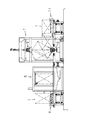
次に、本発明の特徴部分に関して説明する。図5〜図9は本発明の第1実施例の要部を示したものであり、図5は一部断面して示した正面図、図6はその平面図である。また、図7は第1実施例における駆動手段を要部のみ示した正面図、図8はパレットを傾斜させた状態を示した正面図、図9はパレットの遠心脱水時の保持状態を要部のみ示した正面図である。図5に示したように、本実施例では、チェーンコンベヤ等からなる搬入コンベヤ19により遠心脱水室へ搬入されるパレット1の進行方向前方の下部の角部を保持する下方の保持手段20を設け、この保持手段20によりパレット1を保持するとともに角部を支点に進行方向側へ回動して傾斜させる方式を採用した。保持手段20は、図6に示したように内側にパレット1の挿入可能な間隔を隔てて設置される側壁部21,22と、それらの側壁部21,22間に回転可能に支持され、図5に示したようにパレット1の前方の辺部に当接する当接片23と、下方の辺部に当接する当接片24を備える。側壁部21,22は、軸受部25を介して回転のみ可能に支持された回転駆動軸26の上端部に配設した取付部材27に対して支軸28により揺動可能に軸支している。なお、この支軸28は、側壁部21,22に対しては固着状態にあり、取付部材27に対しては回転可能に支持されている。また、その支軸28の中間部は、断面略半円状に形成するなどしてパレット1の角部が支軸28の中心まで挿入し得るように構成している。さらに、図示のように、当接片23,24の外面は、バネ等からなる緩衝用の弾性部材29,30を介して側壁部21,22に固定された支持部材31,32に連結支持されている。そして、当接片23,24間にパレット1が未搬入で弾性部材29,30が圧縮変形する前の状態では、当接片23,24間の内角が直角よりやや小さくなるように設定され、当接片23,24間にパレット1が搬入された場合に、当接片23,24間の内角が少し拡開されて弾性部材29,30の弾性力によりガタのない的確な支持が確保されるように構成している。
【0012】
さらに、前記支持部材31,32の下方には、回転駆動軸26に沿って昇降可能な取付板33を配設し、この取付板33の上昇位置において支持部材31,32の下面に弾接するように、取付板33上にバネ等からなる弾性部材34,35を配設した。なお、取付板33は、スラストベアリング36を介在して昇降ガイド部材37,38に沿って昇降可能に構成された昇降部材39上に設置され、図示しない昇降用シリンダやモータにより駆動される昇降用の送りネジ機構等の昇降用駆動機構により昇降するように構成されている。また、図6及び図7に示したように、側壁部21,22に対して固着状態にある前記支軸28の外部への突出部にはギヤ40を固着し、このギヤ40に対して傾斜用モータ41により駆動される駆動ギヤ42を係脱可能に構成した。すなわち、駆動ギヤ42を、支軸43に固着され該支軸を中心に揺動可能に構成された係脱レバー44の先端部に取付け、同様に前記支軸43に固着された駆動レバー45を揺動用シリンダ46により揺動することにより、前記ギヤ40に対して駆動ギヤ42を歯合させたり、外したり選択できるように構成した。なお、図5に示した回転駆動軸26の下端部に固着されたギヤ47には、図6に示したように、チェーンやタイミングベルト等からなる無端伝動帯48を介して遠心脱水用モータ49の出力軸に固着された駆動ギヤ50に接続されている。なお、図中、51は搬出コンベヤである。
【0013】
しかして、図5に示したように、搬入コンベヤ19により遠心脱水室にパレット1が搬入されると、その進行方向前方の辺部が垂直に立設した待機状態にある当接片23に当接して停止する。この場合、当接片23の位置に関する設定により、パレット1の進行方向前方の下部の角部が、図示のように支軸28の中心部にほぼ一致した位置で停止する。しかる後、図7に示したように駆動ギヤ42がギヤ40に歯合した状態にある場合には直ちに、歯合状態にない場合には揺動用シリンダ46により駆動レバー45を揺動して駆動ギヤ42をギヤ40に歯合させた上、傾斜用モータ41を駆動して駆動ギヤ42とギヤ40との歯合を介して前記支軸28を回動し、側壁部21,22を回動することにより、図8に示したパレット1が傾斜した傾斜状態に移行させる。
【0014】
そして、以上のように、パレット1が図8に示した傾斜状態に移行するに際しては、その移行と同時あるいは移行後に、図示のように昇降ガイド部材37,38に沿って昇降可能に構成された昇降部材39を図示しない昇降用駆動機構により上昇させ、取付板33上に配設した弾性部材34,35を前記支持部材31,32の下面に当接させて、パレット1の傾斜状態を保持する。この場合、前記支持部材31,32の下面に弾性部材34,35の上端部が係合する係合用突起を設けることにより、弾性部材34,35による、より安定的な弾接支持が可能である。しかる後、必要に応じて傾斜用モータ41を駆動してパレット1を図9の傾斜状態にまで傾斜させた上、上方の保持手段52を下降させてパレット1の上方の角部を嵌合保持する。因みに、図8の傾斜状態により上方の保持手段52を下降するだけで、パレット1の上方の角部が保持手段52内に誘導されて嵌合し得る場合には、傾斜用モータ41の駆動による前記傾斜操作は不要である。保持手段52は回転自在に構成されており、パレット1の上方の角部は回転自在に保持される。
【0015】
以上のように、パレット1の上方の角部が保持手段52により回転自在に保持された場合には、前記揺動用シリンダ46により駆動レバー45を介して係脱レバー44を揺動して駆動ギヤ42をギヤ40から離間して歯合関係を解除する。しかる後、遠心脱水用モータ49を始動すれば、その出力軸に固着された駆動ギヤ50に無端伝動帯48を介して接続されたギヤ47が回転を開始し、回転駆動軸26を経て下方の保持手段20が回転駆動され、パレット1が高速回転して遠心脱水が実行されることになる。そして、遠心脱水が終了した場合には、前記揺動用シリンダ46により駆動レバー45を介して係脱レバー44を揺動して駆動ギヤ42をギヤ40に歯合させ、これと前後してパレット1の上方の角部から保持手段52を離脱させた上、傾斜用モータ41を駆動してパレット1を搬出コンベヤ51側に傾斜させ、パレット1をその搬出コンベヤ51に移載して搬出することになる。パレット1の搬出後は、傾斜用モータ41の逆回転等により駆動ギヤ42及びギヤ40を逆回転させて、空の保持手段20を図5の状態に戻すことにより元の待機状態に復帰し、必要に応じて更に以上の動作を繰返すことになる。
【0016】
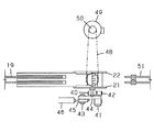
図10は本発明の第2実施例の要部を概略的に示した概略正面図であり、図11はその平面図である。本実施例の場合には、図10に示したようにL字状に形成した当接片53と当接片54から構成され、それらの当接片53,54の根元部分の水平方向の間隔を図11に示したように拡大して空間部を形成した傾斜手段55と、その当接片53,54の根元部分に形成された空間部に設置され、パレット1の下方の角部を嵌合保持する下方の保持手段56を備える点で特徴を有する。すなわち、本実施例では、パレット1を傾斜させる傾斜手段55と、パレット1の下方の角部を嵌合保持する下方の保持手段56とを別々に構成した点で特徴を有する。図11に示したように、当接片53,54の根元部分は、それぞれ支柱57,58に回転可能に支持し、一方の支柱57の外側へ突出する支軸にギヤ59を固着して、このギヤ59に図示しない傾斜用モータの出力軸に固着された駆動ギヤを歯合させた。搬入コンベヤ60により遠心脱水室に搬入されたパレット1は、当接片53,54により支持して、傾斜用モータによりギヤ59を回動することにより図10のように傾斜させる。
【0017】
しかる後、本実施例の場合には、図11に示したように、当接片53,54の根元部分に形成された空間部に設置された下方の保持手段56を支持する昇降支持板61を昇降用モータ62,63により回転される図示しない送りネジ機構等を介して上昇させることにより、下方の保持手段56を当接片53,54の間を通して図10に示したように上昇させるとともに、上方の保持手段64を下降させてパレット1の上下の角部を保持する。そして、パレット1の上下の角部を下方の保持手段56と上方の保持手段64とにより保持できた場合には、遠心脱水用モータ65を始動して、無端伝動帯66を介して下方の保持手段56を回転駆動することにより、パレット1を高速回転して遠心脱水を実行することになる。この遠心脱水が終了した場合には、上方の保持手段64を上昇させてパレット1の上方の角部から離脱させた上、昇降支持板61の下降を介して下方の保持手段56を下降させ、パレット1を前記傾斜手段55に移載する。しかる後、前記ギヤ59を介して傾斜手段55を搬出コンベヤ67側に傾斜させて、パレット1を搬出コンベヤ67に移載した後、前記ギヤ59を介して空の傾斜手段55を逆に搬入コンベヤ60側へ傾斜させることにより待機状態に復帰し、必要に応じて更に以上の動作を繰返すことになる。
【0018】
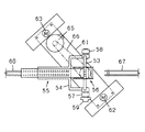
図12は本発明の第3実施例の要部を示した正面図である。図示のように、本実施例の場合には、搬入コンベヤ68と搬出コンベヤ69との間の中央部にパレット1の下方の角部を嵌合保持する下方の保持手段70を送りネジ機構等を用いた昇降機構71を介して昇降可能に配設するとともに、その両側にそれぞれギヤ72〜75を介して揺動可能に構成された当接片76,77を配設した点で特徴を有する。なお、図中、78,79は保持手段70を支持した昇降支持部材80のガイド軸である。しかして、搬入コンベヤ68を介してパレット1が遠心脱水室に搬入されると、実線で示した待機状態の当接片76にパレット1の進行方向前方の辺部が当接して所定位置に停止する。このパレット1の停止位置は、その進行方向前方の辺部が下方の保持手段70のほぼ中央に位置するように当接片76の傾斜角を介して設定する。そして、パレット1が所定位置に停止した場合には、ギヤ72〜75を介して図示しない個々の駆動モータにより当接片76,77の双方を二点鎖線で示したように傾斜させると、パレット1も二点鎖線で示したように傾斜して、下方の角部が下方の保持手段70内に嵌入して保持される。
【0019】
しかる後、必要に応じて下方の保持手段70を昇降機構71により支障のない高さに上昇させるとともに、パレット1の上方の角部を図示しない上方の保持手段内に嵌合保持することにより回転自在に保持する。この上下の保持手段によるパレット1の保持に際しては、当接片76,77の傾斜角を個々に調整することによりパレット1の傾斜角を調整することが可能である。そして、上下の保持手段によるパレット1の保持が完了した場合には、当接片76,77を両側に水平に倒して邪魔にならないように退避させた上、図示しない回転駆動機構により下方の保持手段70を回転駆動することにより、パレット1が高速回転して遠心脱水が実行されることになる。このパレット1の遠心脱水が終了した場合には、上方の保持手段をパレット1の上方の角部から離脱させ、下方の保持手段70を所定位置に下降させた上、当接片76,77の傾斜角を個々に調整しながら、パレット1を搬出コンベヤ69側へ傾斜させて移載した後、当接片76,77をそれぞれ実線で示した状態に戻すことにより待機状態に復帰し、必要に応じて更に以上の動作を繰返すことになる。
【0020】
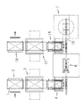
次に、脱水終了時にパレット1を搬入時と異なる角度に停止させて搬出するように構成して、パレット1の角部を保持する保持手段を介して搬入コンベヤと搬出コンベヤとを異なる方向に配設した場合に関して説明する。図13〜図15はその要部のレイアウトに関する配置例を示した概略平面配置図である。図13の配置例の場合には、パレット1は、フォークリフト等の搬送手段により搬入部81に搬入され、その搬入部81において適宜のコンベヤ上に適数枚の積層状態に載置した上、隣接する段ばらし部82へ搬送され、下から2段目のパレット1に昇降用フォークを挿入して2段目以上を持上げて、最下部のパレット1が一枚ずつ起立手段83に搬送される。起立手段83に搬送されたパレット1は、その一辺を底部として載置面が垂直になるように起され、搬入コンベヤ84上に起立状態で載置される。搬入コンベヤ84上に載置されたパレット1は載置面が搬送方向と一致するように起立した状態のまま洗浄室85へ搬送され洗浄が実施される。しかる後、洗浄済みのパレット1は起立状態のまま遠心脱水室86に搬送され遠心脱水が実施される。本例では、この遠心脱水が終了してパレットを停止する際には、適宜の部位に設置した光電センサやパレット1の保持手段の回転駆動軸等に設置したロータリエンコーダなどによりパレット1の角度を検出して、搬入方向と直交する方向で載置面となる表面が紙面右側となるように停止制御する。そして、搬入方向と直交する方向に停止されたパレット1は、一辺を底部とする起立状態に戻して搬入コンベヤ84と直交する方向に配設された搬出コンベヤ87上に移載される。この場合、2方差しパレットでは、フォーク差込み孔が水平方向の状態で搬入コンベヤ84から遠心脱水室86に搬入され、搬出時にも同様にフォーク差込み孔が水平方向の状態で搬出コンベヤ87上へ移載される。搬出コンベヤ87上に移載された脱水済みのパレット1は、転倒手段88により水平状態に転倒されて適宜のコンベヤ上に載置され、隣接する段積み部89へ1枚ずつ搬送され、その段積み部89において既に積層済みのパレット1を持上げて最下部へ挿入することにより順次所定の段数に積重ねられ、搬出部90からフォークリフト等の搬送手段により搬出されることになる。この配置例の場合には、搬入コンベヤ84の搬送方向を逆転することなく、遠心脱水室86や洗浄室85に隣接するスペースを有効に使用することができる。
【0021】
図14の配置例は、図13の配置例の変形例であり、前記遠心脱水室86からの搬出コンベヤ91を搬入コンベヤ84に対して逆の方向へ直交するように配設し、この搬出コンベヤ91の下流側に転倒手段92、方向変換部93、段積み部94、搬出部95をそれぞれ接続したものである。図示のように、本配置例の場合には、搬入部81と搬出部95とを接近した場所に設置できる点で特徴を有する。さらに、図15の配置例の場合は、図13の配置例と図14の配置例とを組合わせたものであり、図示のように前記搬入コンベヤ84に対して左右に直交する方向に搬出コンベヤ87と搬出コンベヤ91を接続し、さらにそれらの搬出コンベヤ87,91に対して前記下流側の各構成部を接続したものである。本配置例の場合には、パレット1のサイズ等により左右の搬出コンベヤ87と搬出コンベヤ91に振分けて搬出することも可能である。
【0022】
【発明の効果】
本発明によれば、搬入コンベヤにより表裏面を搬送方向に一致させた状態で搬入されるパレットを該搬入コンベヤの一端に配設した前記傾斜手段により前方下部の角部の回りに回動して一つの角部が底部となるように傾斜させ、その傾斜状態のパレットの一対の角部を、少なくとも水平方向の位置変更を伴うことなく、同じく搬入コンベヤの一端に配設した前記保持手段により保持して回転するように構成したので、パレットの回転部への搬入搬出は、搬入コンベヤを経てその一端に配設した前記傾斜手段へ直接的に移載したり、その傾斜手段から直接的に搬出コンベヤへ移載することにより可能なことから、対象パレットの搬入搬出が大幅に簡素化される。また、前記傾斜手段によりパレットを傾斜させた位置において、水平方向の位置変更を伴うことなく、そのまま前記保持手段により前記パレットの一対の角部を保持して回転するように構成したので、装置としての運転効率の向上やレイアウト上の省スペース化にきわめて有効である。さらに、脱水終了時にパレットを搬入時と異なる角度に停止させて搬出するように構成することにより、パレットの角部を保持する保持手段を介して搬入コンベヤと搬出コンベヤとを異なる方向に配設することも可能となり、レイアウト上の自由度が向上される。
【図面の簡単な説明】
【図1】 本発明の要部のレイアウトに関する第1配置例を示した概略平面配置図である。
【図2】 同配置例を正面からみた正面配置図である。
【図3】 本発明の要部のレイアウトに関する第2配置例を示した概略平面配置図である。
【図4】 同配置例を正面からみた正面配置図である。
【図5】 本発明の第1実施例の要部を示した正面図である。
【図6】 同実施例の平面図である。
【図7】 同実施例における駆動手段を要部のみ示した正面図である。
【図8】 同実施例においてパレットを傾斜させた状態を示した正面図である。
【図9】 同実施例におけるパレットの遠心脱水時の保持状態を要部のみ示した正面図である。
【図10】 本発明の第2実施例の要部を概略的に示した概略正面図である。
【図11】 同実施例の平面図である。
【図12】 本発明の第3実施例の要部を示した正面図である。
【図13】 本発明の要部のレイアウトに関する他の配置例を示した概略平面配置図である。
【図14】 本発明の要部のレイアウトに関する他の配置例を示した概略平面配置図である。
【図15】 本発明の要部のレイアウトに関する他の配置例を示した概略平面配置図である。
【符号の説明】
1…パレット、2…搬入部、3…段ばらし部、4…起立手段、5…搬入コンベヤ、6…洗浄室、7…遠心脱水室、8,9…保持手段、10…搬出コンベヤ、11…転倒手段、12…方向変換部、13…段積み部、14…搬出部、15…搬入搬出コンベヤ、16…転倒手段、17…段積み部、18…搬出部、19…搬入コンベヤ、20…保持手段、21,22…側壁部、23,24…当接片、25…軸受部、26…回転駆動軸、27…取付部材、28…支軸、29,30…弾性部材、31,32…支持部材、33…取付板、34,35…弾性部材、36…スラストベアリング、37,38…昇降ガイド部材、39…昇降部材、40…ギヤ、41…傾斜用モータ、42…駆動ギヤ、43…支軸、44…係脱レバー、45…駆動レバー、46…揺動用シリンダ、47…ギヤ、48…無端伝動帯、49…遠心脱水用モータ、50…駆動ギヤ、51…搬出コンベヤ、52…保持手段、53,54…当接片、55…傾斜手段、56…保持手段、57,58…支柱、59…ギヤ、60…搬入コンベヤ、61…昇降支持板、62,63…昇降用モータ、64…保持手段、65…遠心脱水用モータ、66…無端伝動帯、67…搬出コンベヤ、68…搬入コンベヤ、69…搬出コンベヤ、70…保持手段、71…昇降機構、72〜75…ギヤ、76,77…当接片、78,79…ガイド軸、80…昇降支持部材、81…搬入部、82…段ばらし部、83…起立手段、84…搬入コンベヤ、85…洗浄室、86…遠心脱水室、87…搬出コンベヤ、88…転倒手段、89…段積み部、90…搬出部、91…搬出コンベヤ、92…転倒手段、93…方向変換部、94…段積み部、95…搬出部[0001]
BACKGROUND OF THE INVENTION
The present invention relates to a centrifugal dewatering device for a pallet for centrifugally dehydrating a washed liquid or the like adhering to a rectangular workpiece (hereinafter simply referred to as a pallet) such as a pallet or a tray container similar to the pallet.
[0002]
[Prior art]
With regard to this kind of pallet dewatering device, the pallets stacked in a horizontal state on a magazine or the like are taken out one by one and washed in an upright state with the pallet mounting surface upright, and then after the washing. 2. Description of the Related Art Conventionally, a pallet is rotated in a standing state, subjected to centrifugal dehydration treatment, returned to a horizontal state, stacked and carried out (Patent Document 1). By the way, in this prior art, since the pallet is rotated in an upright state, the liquid remaining in the recess formed on the pallet can be effectively removed, but the center of rotation tends to shift when the pallet is held. For this reason, there is a technical problem that the risk of unbalance increases if the rotation is continued. Under such circumstances, in the case of the above-described prior art, the holder tends to be complicated and large in order to hold the pallet firmly. In general, the number of types of pallets handled is very large, but it is also difficult to use pallets of different sizes on the same device. Therefore, the present applicant has proposed that the pallet is centrifugally dehydrated with a pair of corners on the diagonal line aligned with the rotation axis (Patent Document 2). Here, the diagonal of the pallet means a square or rectangular diagonal when the pallet is viewed in plan. In the case of this dehydration method, a pair of corners on the diagonal line of the pallet are rotated at a high speed by matching the rotation axis, so that the center of rotation of the pallet is shifted as in the prior art, and there is a risk of unbalance. The technical problem that occurs is solved. Furthermore, since the pair of corners on the diagonal line of the pallet is supported, it is possible to easily cope with pallets of different sizes. However, in the case of this dehydration method, it is necessary to incline and rotate the pallet in order to align the pair of corners on the diagonal line of the pallet with the rotation axis. Carrying out has become complicated, which has had an impact on efficient operation.
[0003]
[Patent Document 1]
Japanese Utility Model Publication No. 6-52973
[Patent Document 2]
JP 2002-333272 A
[0004]
[Problems to be solved by the invention]
In view of the conventional technical situation as described above, the present invention inclines the pallet while inheriting the advantages of the dewatering method in which centrifugal dewatering is performed by matching the pair of corners on the diagonal line of the pallet with the rotation axis. To improve the linkage between the tilting mechanism for rotating the pallet and the rotating mechanism for rotating the pallet, thereby simplifying the loading and unloading of the pallet. The purpose is to save space.
[0005]
[Means for Solving the Problems]
In order to solve the above-mentioned problem, in the invention of
[0006]
According to a fifth aspect of the present invention, there is provided a pallet centrifugal dewatering apparatus provided with a holding means for performing centrifugal dewatering by holding a pair of corners on a diagonal line of the pallet so as to coincide with the rotation axis. Transport with one side at the bottom and the front and back sides aligned with the transport direction And a conveyor that stops at a different angle after loading. Be Remove the pallet from the holding means The one side is the bottom and the front and back surfaces are transported in the transport direction. The transport direction is different from the carry-in conveyor. Unloading conveyor Ya The technical means of providing was adopted. According to the present invention, the carry-in conveyor and the carry-out conveyor can be arranged at different angles via the holding means for performing centrifugal dehydration. For example, The carry-in conveyor and the carry-out conveyor may be arranged so that their conveyance directions are orthogonal to each other (claims). 6 ). When the pallet is carried from the carry-in conveyor to the holding means, the pallet with one side at the bottom is changed to a state where one corner is the bottom, and when the pallet is carried from the holding means to the carry-out conveyor, Inclination means may be provided for changing from a state in which one corner is a bottom to a state in which one side is a bottom. 7 ).
[0007]
DETAILED DESCRIPTION OF THE INVENTION
The present invention can be widely applied to the removal of liquid adhering to a square or rectangular pallet. Generally, in the case of a resin pallet, a pallet having a weight of about 10 to 30 kg and a thickness of about 130 mm to 150 mm is used, but the present invention is not limited to these forms and can be widely applied. In addition, there are two-way pallet and four-way pallet for the fork insertion form, but it goes without saying that it can be applied to both forms. Furthermore, it can be easily adapted to pallets with different vertical and horizontal sizes and aspect ratios. In addition, regarding the carrying-out direction when carrying out the dehydrated pallet from the rotating part, it may be set so as to return to the same side as the carrying-in side with respect to the rotating part, and opposite to the carrying-in side across the rotating part. You may set so that it may carry out to the side of this, and you may set so that it may carry out in the orthogonal direction. Moreover, you may comprise so that an inclination means may serve as a holding means below. Further, it is possible to arrange the cleaning nozzle and the centrifugal dewatering unit in the same chamber by arranging the cleaning nozzle around the pallet that is rotationally driven.
[0008]
【Example】
Hereinafter, embodiments of the present invention will be described with reference to the drawings. FIG. 1 is a schematic plan view showing a first arrangement example relating to the layout of the main part of the present invention, and FIG. 2 is a front view seen from the front. The
[0009]
The cleaned
[0010]
FIG. 3 is a schematic plan view showing a second arrangement example relating to the layout of the main part of the present invention, and FIG. 4 is a front view seen from the front. As shown in the figure, in the case of this arrangement example, a carry-in / out conveyor that serves as a carry-in conveyor for the
[0011]
Next, the characteristic part of the present invention will be described. 5 to 9 show the main part of the first embodiment of the present invention. FIG. 5 is a partially sectional front view, and FIG. 6 is a plan view thereof. 7 is a front view showing only a main part of the driving means in the first embodiment, FIG. 8 is a front view showing a state where the pallet is inclined, and FIG. 9 is a main part showing a holding state during centrifugal dehydration of the pallet. It is the front view which showed only. As shown in FIG. 5, in this embodiment, the lower side in the forward direction of the
[0012]
Further, a mounting
[0013]
Thus, as shown in FIG. 5, when the
[0014]
As described above, when the
[0015]
As described above, when the upper corner portion of the
[0016]
FIG. 10 is a schematic front view schematically showing the main part of the second embodiment of the present invention, and FIG. 11 is a plan view thereof. In the case of the present embodiment, as shown in FIG. 10, it is composed of an abutting
[0017]
Thereafter, in the case of the present embodiment, as shown in FIG. 11, ascending / descending
[0018]
FIG. 12 is a front view showing the main part of the third embodiment of the present invention. As shown in the figure, in the case of the present embodiment, a lower holding means 70 for fitting and holding the lower corner of the
[0019]
Thereafter, if necessary, the lower holding means 70 is raised to an unobstructed height by the elevating
[0020]
Next, when dehydration is completed, the
[0021]
The arrangement example of FIG. 14 is a modification of the arrangement example of FIG. 13, and the carry-out
[0022]
【The invention's effect】
According to the present invention, the carry-in conveyor With the front and back sides aligned with the transport direction The pallet to be carried in by the tilting means disposed at one end of the carry-in conveyor Rotate around the lower corner of the front Inclined so that one corner is the bottom, and the pair of corners of the tilted pallet is held by the holding means arranged at one end of the carry-in conveyor at least without changing the position in the horizontal direction. Since the pallet is configured to rotate, loading / unloading of the pallet to / from the rotating part is carried directly to the tilting means disposed at one end thereof via the carry-in conveyor, or directly from the tilting means. Since it is possible by transferring to the conveyor, the loading and unloading of the target pallet is greatly simplified. Further, at the position where the pallet is inclined by the inclination means, without a horizontal position change, As it is Since the holding means holds and rotates the pair of corners of the pallet, it is extremely effective in improving the operation efficiency of the apparatus and saving the layout space. In addition, when the dehydration is completed, the pallet is stopped at an angle different from that at the time of carry-in and carried out, whereby the carry-in conveyor and the carry-out conveyor are arranged in different directions via holding means for holding the corners of the pallet. This also improves the degree of freedom in layout.
[Brief description of the drawings]
FIG. 1 is a schematic plan view showing a first arrangement example related to a layout of a main part of the present invention.
FIG. 2 is a front view of the same arrangement example as viewed from the front.
FIG. 3 is a schematic plan view showing a second arrangement example regarding the layout of the main part of the present invention.
FIG. 4 is a front view of the same arrangement example as viewed from the front.
FIG. 5 is a front view showing the main part of the first embodiment of the present invention.
FIG. 6 is a plan view of the same embodiment.
FIG. 7 is a front view showing only the main part of the driving means in the embodiment.
FIG. 8 is a front view showing a state where the pallet is inclined in the embodiment.
FIG. 9 is a front view showing only a main part of the pallet holding state during centrifugal dewatering in the same embodiment.
FIG. 10 is a schematic front view schematically showing a main part of a second embodiment of the present invention.
FIG. 11 is a plan view of the same embodiment.
FIG. 12 is a front view showing a main part of a third embodiment of the present invention.
FIG. 13 is a schematic plan layout diagram illustrating another layout example related to the layout of the main part of the present invention.
FIG. 14 is a schematic plan view showing another arrangement example related to the layout of the main part of the present invention.
FIG. 15 is a schematic plan view showing another arrangement example related to the layout of the main part of the present invention.
[Explanation of symbols]
DESCRIPTION OF
Claims (7)
Priority Applications (1)
| Application Number | Priority Date | Filing Date | Title |
|---|---|---|---|
| JP2003168527A JP3961988B2 (en) | 2003-06-12 | 2003-06-12 | Pallet centrifugal dehydrator |
Applications Claiming Priority (1)
| Application Number | Priority Date | Filing Date | Title |
|---|---|---|---|
| JP2003168527A JP3961988B2 (en) | 2003-06-12 | 2003-06-12 | Pallet centrifugal dehydrator |
Publications (2)
| Publication Number | Publication Date |
|---|---|
| JP2005003295A JP2005003295A (en) | 2005-01-06 |
| JP3961988B2 true JP3961988B2 (en) | 2007-08-22 |
Family
ID=34093944
Family Applications (1)
| Application Number | Title | Priority Date | Filing Date |
|---|---|---|---|
| JP2003168527A Expired - Fee Related JP3961988B2 (en) | 2003-06-12 | 2003-06-12 | Pallet centrifugal dehydrator |
Country Status (1)
| Country | Link |
|---|---|
| JP (1) | JP3961988B2 (en) |
Cited By (2)
| Publication number | Priority date | Publication date | Assignee | Title |
|---|---|---|---|---|
| CN102261823A (en) * | 2011-06-18 | 2011-11-30 | 津伦(天津)精密机械股份有限公司 | Inclined liquid removal machine |
| CN109059512A (en) * | 2018-07-26 | 2018-12-21 | 蚌埠淮畔精密机械有限公司 | A kind of glass drying device |
Families Citing this family (3)
| Publication number | Priority date | Publication date | Assignee | Title |
|---|---|---|---|---|
| JP4568251B2 (en) * | 2006-06-08 | 2010-10-27 | 株式会社カネヤス | Dehydrator capable of handling multiple types of pallets and cleaning equipment using the same |
| JP4781936B2 (en) * | 2006-08-08 | 2011-09-28 | シブヤマシナリー株式会社 | Pallet centrifugal dehydrator |
| KR101470195B1 (en) * | 2013-07-25 | 2014-12-05 | 양희준 | Horizontal form multi stage loading type palette washing device and washing method |
-
2003
- 2003-06-12 JP JP2003168527A patent/JP3961988B2/en not_active Expired - Fee Related
Cited By (3)
| Publication number | Priority date | Publication date | Assignee | Title |
|---|---|---|---|---|
| CN102261823A (en) * | 2011-06-18 | 2011-11-30 | 津伦(天津)精密机械股份有限公司 | Inclined liquid removal machine |
| CN102261823B (en) * | 2011-06-18 | 2015-06-24 | 津伦(天津)精密机械股份有限公司 | Inclined liquid removal machine |
| CN109059512A (en) * | 2018-07-26 | 2018-12-21 | 蚌埠淮畔精密机械有限公司 | A kind of glass drying device |
Also Published As
| Publication number | Publication date |
|---|---|
| JP2005003295A (en) | 2005-01-06 |
Similar Documents
| Publication | Publication Date | Title |
|---|---|---|
| CN101246813B (en) | Substrate processing apparatus | |
| KR20060086794A (en) | Conveyor system for glass substrate and the like | |
| JP3961988B2 (en) | Pallet centrifugal dehydrator | |
| CN208048496U (en) | logistics shelf | |
| JP4009316B2 (en) | Pallet cleaning method and apparatus | |
| CN112357489A (en) | Movable box turnover device | |
| JP3999529B2 (en) | Pallet cleaning device | |
| JP4386259B2 (en) | Pallet delivery device in pallet centrifugal dehydrator | |
| JP2691890B2 (en) | Concrete product reversing machine | |
| JP3220042B2 (en) | Concrete product reversing machine | |
| JP4383714B2 (en) | Pallet transfer method and apparatus | |
| CN219294139U (en) | Material conveying mechanism of circular cutter machine | |
| JP3875115B2 (en) | Pallet centrifugal dehydrator | |
| CN220617382U (en) | Tray overturning machine for dumping products | |
| JP4515649B2 (en) | Substrate angle conversion device | |
| CN216888990U (en) | Steering transmission mechanism and equipment | |
| CN214166348U (en) | Movable box turnover device | |
| CN213894173U (en) | Automatic material conveying equipment | |
| JP7307756B2 (en) | Tableware reversing device, tray transport reversing system and tray back system | |
| CN214086202U (en) | Tray type elevator | |
| JP2003206020A (en) | Article attitude changing device | |
| JP3041580U (en) | Conveyor line transfer attitude control device | |
| CN117945117A (en) | Curved block continuous overturning and charging device and use method | |
| JP4148467B2 (en) | Plate-shaped member supply device and discharge device | |
| JPH0637231U (en) | Wheel reversing transfer device |
Legal Events
| Date | Code | Title | Description |
|---|---|---|---|
| A621 | Written request for application examination |
Free format text: JAPANESE INTERMEDIATE CODE: A621 Effective date: 20050927 |
|
| A131 | Notification of reasons for refusal |
Free format text: JAPANESE INTERMEDIATE CODE: A131 Effective date: 20070214 |
|
| A521 | Request for written amendment filed |
Free format text: JAPANESE INTERMEDIATE CODE: A523 Effective date: 20070410 |
|
| TRDD | Decision of grant or rejection written | ||
| A01 | Written decision to grant a patent or to grant a registration (utility model) |
Free format text: JAPANESE INTERMEDIATE CODE: A01 Effective date: 20070515 |
|
| A61 | First payment of annual fees (during grant procedure) |
Free format text: JAPANESE INTERMEDIATE CODE: A61 Effective date: 20070517 |
|
| R150 | Certificate of patent or registration of utility model |
Ref document number: 3961988 Country of ref document: JP Free format text: JAPANESE INTERMEDIATE CODE: R150 Free format text: JAPANESE INTERMEDIATE CODE: R150 |
|
| FPAY | Renewal fee payment (event date is renewal date of database) |
Free format text: PAYMENT UNTIL: 20100525 Year of fee payment: 3 |
|
| FPAY | Renewal fee payment (event date is renewal date of database) |
Free format text: PAYMENT UNTIL: 20110525 Year of fee payment: 4 |
|
| FPAY | Renewal fee payment (event date is renewal date of database) |
Free format text: PAYMENT UNTIL: 20120525 Year of fee payment: 5 |
|
| FPAY | Renewal fee payment (event date is renewal date of database) |
Free format text: PAYMENT UNTIL: 20130525 Year of fee payment: 6 |
|
| S111 | Request for change of ownership or part of ownership |
Free format text: JAPANESE INTERMEDIATE CODE: R313115 |
|
| R350 | Written notification of registration of transfer |
Free format text: JAPANESE INTERMEDIATE CODE: R350 |
|
| LAPS | Cancellation because of no payment of annual fees |