JP3961745B2 - Misfire detection device for internal combustion engine - Google Patents
Misfire detection device for internal combustion engine Download PDFInfo
- Publication number
- JP3961745B2 JP3961745B2 JP2000187122A JP2000187122A JP3961745B2 JP 3961745 B2 JP3961745 B2 JP 3961745B2 JP 2000187122 A JP2000187122 A JP 2000187122A JP 2000187122 A JP2000187122 A JP 2000187122A JP 3961745 B2 JP3961745 B2 JP 3961745B2
- Authority
- JP
- Japan
- Prior art keywords
- internal combustion
- combustion engine
- misfire
- determination level
- rotational speed
- Prior art date
- Legal status (The legal status is an assumption and is not a legal conclusion. Google has not performed a legal analysis and makes no representation as to the accuracy of the status listed.)
- Expired - Fee Related
Links
Images


Description
【0001】
【発明の属する技術分野】
本発明は、内燃機関に発生する失火を検出する内燃機関の失火検出装置に関するものである。
【0002】
【従来の技術】
従来、内燃機関の失火検出の実行に際し、通常、内燃機関の失火検出用の判定レベルとしては、機関回転速度及び負荷をパラメータとする二次元マップに基づき補間され設定されている。この設定された判定レベルを用いて内燃機関に発生する失火が検出されている。
【0003】
【発明が解決しようとする課題】
ところで、内燃機関の機関回転速度及び負荷が同じであっても、正確に失火検出でき、かつ、誤検出を生じない判定レベルとして、内燃機関の運転状態に応じてその要求値が異なることがあった。
【0004】
例えば、排気ガスを浄化する三元触媒を早期に活性化するための触媒早期暖機制御中とその制御中でない通常の運転状態とでは、内燃機関の機関回転速度及び負荷が同じであるにもかかわらず燃焼状態が異なっており、要求される失火検出のための判定レベルは同じではない。このため、通常の運転状態で適合されたマップに基づき、そのときの機関回転速度及び負荷で補間され設定された判定レベルを用い、触媒早期暖機制御中に失火検出を行うと誤検出または誤判定が発生するという不具合があった。
【0005】
そこで、この発明はかかる不具合を解決するためになされたもので、内燃機関の運転状態に応じて正確に失火検出可能な内燃機関の失火検出装置の提供を課題としている。
【0006】
【課題を解決するための手段】
請求項1の内燃機関の失火検出装置によれば、内燃機関の失火を判定するための判定レベルが、内燃機関の通常の運転状態で設定される値に比して、それ以外の特定の運転状態として内燃機関の燃焼状態に影響を及ぼす触媒早期暖機制御中に設定される値が小さく設定され、機関回転速度の平均回転速度変化量の大きな変動のみを捉えるように、それぞれ対応して設定されている。これにより、内燃機関の所定の運転状態に対応する判定レベルとそのときの平均回転速度変化量とが比較できるため、内燃機関の通常の運転状態に限らず内燃機関の燃焼状態に影響を及ぼすような触媒早期暖機制御中であっても失火の有無が正確に判定される。
【0008】
【発明の実施の形態】
以下、本発明の実施の形態を実施例に基づいて説明する。
【0009】
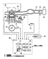
図1は本発明の実施の形態の一実施例にかかる内燃機関の失火検出装置の全体構成を示す概略図である。
【0010】
図1において、10は4サイクルV型6気筒(#1気筒〜#6気筒)からなる内燃機関であり、11はエアクリーナ12から導入される吸入空気を内燃機関10側に供給する吸気通路である。13は吸気通路11内に導入される吸気量GN〔g/rev〕を検出するエアフローメータ等の吸気量センサである。
【0011】
21は内燃機関10のクランク軸16に配設され、所定クランク角毎に信号を出力し機関回転速度NE〔rpm〕を求めるための回転速度センサであり、23はディストリビュータ22に内蔵され、特定気筒を判別するための信号を出力、例えば、#1気筒のピストン17が最も上昇した時点である圧縮TDC(Top Dead Center:上死点)毎の基準位置Gを検出する基準位置センサである。24は内燃機関10の冷却水路に配設され、冷却水温THW〔℃〕を検出する水温センサである。
【0012】
30は吸気量センサ13からの吸気量GN信号、回転速度センサ21からの機関回転速度NE信号、基準位置センサ23からの基準位置G、水温センサ24からの冷却水温THW信号、その他の各種センサ信号を入力し、燃料系及び点火系における最適な制御量を演算し、インジェクタ(燃料噴射弁)26及びイグナイタ27等を的確に制御するための制御信号を出力するECU(Electronic Control Unit:電子制御ユニット)である。
【0013】
ECU30は、周知の各種演算処理を実行する中央処理装置としてのCPU31、制御プログラムを格納したROM32、各種データを格納するRAM33、B/U(バックアップ)RAM34、入出力回路35及びそれらを接続するバスライン36等からなる論理演算回路として構成されている。なお、29はECU30によって失火発生と判断されたときに、失火発生を運転者等に知らせるための警告ランプである。
【0014】
次に、本発明の実施の形態の一実施例にかかる内燃機関の失火検出装置で使用されているECU30内のCPU31における失火有無判定の処理手順を示す図2のフローチャートに基づき、図3乃至図6を参照して説明する。なお、この失火有無判定ルーチンは所定クランク角、例えば、30〔°CA(Crank Angle)〕毎の割込にて繰返し実行される。
【0015】
ここで、図3は内燃機関10の通常の運転状態における失火有無を判定するための判定レベルを算出するマップであり、図4は内燃機関10の通常の運転状態における点火回数〔回〕毎の平均回転速度変化量Δω〔rpm〕と失火有無を判定するための判定レベルREF1との関係を示す特性図であり、図4(a)は失火なし時、図4(b)は失火有り時を示す。また、図5は内燃機関10の特定の運転状態として触媒早期暖機制御中における失火有無を判定するための判定レベルを算出するマップであり、図6は内燃機関10の触媒早期暖機制御中における点火回数〔回〕毎の平均回転速度変化量Δω〔rpm〕と失火有無を判定するための判定レベルREF2との関係を示す特性図であり、図6(a)は失火なし時、図6(b)は失火有り時を示す。
【0016】
図2において、まず、ステップS101では、前回の割込時刻と今回の割込時刻との偏差からクランク軸16が30〔°CA〕回転するのに要する今回の時間T30i が算出される。次にステップS102に移行して、今回の割込タイミングが#1気筒〜#6気筒のうち何れか1つの気筒における圧縮TDCであるかが判定される。ステップS102の判定条件が成立せず、即ち、今回の割込タイミングが圧縮TDCでないときには何もすることなく本ルーチンを終了する。
【0017】
一方、ステップS102の判定条件が成立、即ち、今回の割込タイミングが#1気筒の圧縮TDCであるときにはステップS103に移行し、ステップS101で算出された今回の時間T30i と、前回、前々回及び3回前の実行時にそれぞれ算出された時間T30i-1 ,T30i-2 ,T30i-3 との全4回分のデータが累計され、クランク軸16が120〔°CA〕回転するのに要する時間T120i が算出される。
【0018】
次にステップS104に移行して、ステップS103で算出されたクランク軸16が120〔°CA〕回転するのに要する時間T120i の逆数にて、内燃機関10の今回の平均回転速度ωn が算出される。次にステップS105に移行して、今回の平均回転速度変化量Δωn が次式(1)にて算出される。ここで、ωn-1 は前回、ωn-3 は3回前、ωn-4 は4回前の実行時にそれぞれ算出された平均回転速度である。また、(ωn-1 −ωn )は膨張(爆発)行程が連続する気筒における最新の回転速度変化量であり、(ωn-4 −ωn-3 )は膨張(爆発)行程が連続する気筒における360〔°CA〕前の回転速度変化量である。
【0019】
【数1】
Δωn =(ωn-1 −ωn )−(ωn-4 −ωn-3 ) ・・・(1)
【0020】
次にステップS106に移行して、内燃機関10の特定の運転状態として触媒早期暖機制御中であるかが判定される。ステップS106の判定条件が成立せず、即ち、触媒早期暖機制御中でなく通常の運転状態であるときにはステップS107に移行し、図3に示すように、例えば、機関回転速度NE=1500〔rpm〕及び負荷としての吸気量GN=0.8〔g/rev〕に対応するマップ値、即ち、通常の運転状態における失火有無を判定するための判定レベルREF1が補間演算にて算出される。
【0021】
ここで、図4を参照して、図3の内燃機関10の通常の運転状態における失火有無を判定するための判定レベルREF1を算出するためのマップ値の設定について説明する。
【0022】
図4(a)に示す内燃機関10の通常の運転状態で失火なし時では、平均回転速度変化量Δωの変動は小さい。これに対して、図4(b)に示すように、内燃機関10の通常の運転状態で失火有り時では、平均回転速度変化量Δωの変動が失火気筒に対応する所定のタイミングにて極端に大きく現われる。したがって、内燃機関10の通常の運転状態においては、平均回転速度変化量Δωの大きな変動のみを捉えるよう、図4(b)に一点鎖線にて示す判定レベルREF1(=200〔rpm〕)が設定される。
【0023】
次にステップS108に移行して、今回の平均回転速度変化量Δωn がステップS107で算出された判定レベルREF1を越えているかが判定される。ステップS108の判定条件が成立せず、即ち、今回の平均回転速度変化量Δωn が判定レベルREF1以下と小さいときにはステップS109に移行し、通常の運転状態で失火なしと確定され本ルーチンを終了する。
【0024】
一方、ステップS106の判定条件が成立、即ち、触媒早期暖機制御中であるときにはステップS110に移行し、図5に示すように、例えば、機関回転速度NE=1500〔rpm〕及び負荷としての吸気量GN=0.8〔g/rev〕に対応するマップ値、即ち、触媒早期暖機制御中における失火有無を判定するための判定レベルREF2が補間演算にて算出される。
【0025】
ここで、図6を参照して、図5の内燃機関10の触媒早期暖機制御中における失火有無を判定するための判定レベルREF2を算出するためのマップ値の設定について説明する。
【0026】
図6(a)に示す内燃機関10の触媒早期暖機制御中で失火なし時では、上述の図4(a)に示す通常の運転状態で失火なし時に比べて、平均回転速度変化量Δωの変動はやや大きくなることが分かる。これに対して、図6(b)に示す内燃機関10の触媒早期暖機制御中で失火有り時では、平均回転速度変化量Δωの変動が失火気筒に対応する所定のタイミングにて明らかに大きく現われる。したがって、内燃機関10の触媒早期暖機制御中においては、平均回転速度変化量Δωの大きな変動のみを捉えるよう、図6(b)に一点鎖線にて示す判定レベルREF2(=100〔rpm〕)が設定される。
【0027】
次にステップS111に移行して、今回の平均回転速度変化量Δωn がステップS110で算出された判定レベルREF2を越えているかが判定される。ステップS111の判定条件が成立、即ち、今回の平均回転速度変化量Δωn が判定レベルREF2を越え大きいときにはステップS112に移行し、触媒早期暖機制御中で失火有りと確定され本ルーチンを終了する。
【0028】
なお、ステップS108の判定条件が成立、即ち、今回の平均回転速度変化量Δωn が判定レベルREF1を越え大きいときにはステップS112に移行し、内燃機関10の通常の運転状態で失火有りと確定され本ルーチンを終了する。また、ステップS111の判定条件が成立せず、即ち、今回の平均回転速度変化量Δωn が判定レベルREF2以下と小さいときにはステップS113に移行し、内燃機関10の触媒早期暖機制御中で失火なしと確定され本ルーチンを終了する。
【0029】
このように、本実施例の内燃機関の失火検出装置は、内燃機関10の機関回転速度NEを検出する回転速度検出手段としての回転速度センサ21と、回転速度センサ21で検出される機関回転速度NEの平均回転速度変化量Δωを算出するECU30内のCPU31にて達成される変化量演算手段と、内燃機関10の通常の運転状態、またはそれ以外の特定の運転状態における平均回転速度変化量Δωに対し、それぞれ失火を判定するための判定レベルREF1,REF2を設定するECU30内のCPU31にて達成される判定レベル設定手段と、前記変化量演算手段で算出された平均回転速度変化量Δωを前記判定レベル設定手段で設定された内燃機関10の所定の運転状態に対応する判定レベルと比較し、内燃機関10における失火の有無を判定するECU30内のCPU31にて達成される失火判定手段とを具備し、特定の運転状態が内燃機関10の燃焼状態に影響を及ぼす触媒早期暖機制御中であり、前記判定レベル設定手段により設定される判定レベルREF1,REF2が前記変化量演算手段により算出される機関回転速度NEの平均回転速度変化量Δωの大きな変動のみを捉えるように設定されるものである。
【0030】
つまり、内燃機関10の失火を判定するための判定レベルREF1,REF2が、内燃機関10の通常の運転状態、またはそれ以外の特定の運転状態として内燃機関10の燃焼状態に影響を及ぼす触媒早期暖機制御中における機関回転速度NEの平均回転速度変化量Δωの大きな変動のみを捉えるように、それぞれ予め設定されている。これにより、内燃機関10の所定の運転状態に対応する判定レベルとそのときの平均回転速度変化量Δωとが比較できるため、内燃機関10の通常の運転状態に限らず内燃機関10の燃焼状態に影響を及ぼすような触媒早期暖機制御中であっても失火の有無を正確に判定することができる。
【0032】
ところで、上記実施例では、内燃機関10の特定の運転状態として触媒早期暖機制御中について述べたが、本発明を実施する場合には、これに限定されるものではなく、その他、内燃機関10の燃焼状態に影響を及ぼす運転状態に対応して失火有無を判定するための判定レベルを個々に設定することで、失火の有無を正確に判定することができる。
【図面の簡単な説明】
【図1】 図1は本発明の実施の形態の一実施例にかかる内燃機関の失火検出装置の全体構成を示す概略図である。
【図2】 図2は本発明の実施の形態の一実施例にかかる内燃機関の失火検出装置で使用されているECU内のCPUにおける失火有無判定の処理手順を示すフローチャートである。
【図3】 図3は図2の内燃機関の通常の運転状態における失火有無を判定するための判定レベルを算出するマップである。
【図4】 図4は図3のマップにおける失火有無を判定するための判定レベルと点火回数毎の平均回転速度変化量との関係を示す特性図である。
【図5】 図5は図2の内燃機関の触媒早期暖機制御中における失火有無を判定するための判定レベルを算出するマップである。
【図6】 図6は図5のマップにおける失火有無を判定するための判定レベルと点火回数毎の平均回転速度変化量との関係を示す特性図である。
【符号の説明】
10 内燃機関
21 回転速度センサ(回転速度検出手段)
30 ECU(電子制御ユニット)
31 CPU[0001]
BACKGROUND OF THE INVENTION
The present invention relates to a misfire detection apparatus for an internal combustion engine that detects misfire occurring in the internal combustion engine.
[0002]
[Prior art]
Conventionally, when performing misfire detection of an internal combustion engine, the determination level for detecting misfire of the internal combustion engine is usually set by interpolation based on a two-dimensional map using engine speed and load as parameters. Misfire that occurs in the internal combustion engine is detected using the set determination level.
[0003]
[Problems to be solved by the invention]
By the way, even if the engine speed and load of the internal combustion engine are the same, the required value may differ depending on the operating state of the internal combustion engine as a determination level that can accurately detect misfire and does not cause erroneous detection. It was.
[0004]
For example, the engine rotational speed and load of the internal combustion engine are the same during the early catalyst warm-up control for early activation of the three-way catalyst for purifying exhaust gas and in the normal operating state during which the control is not being performed. Regardless, the combustion state is different and the required judgment level for misfire detection is not the same. For this reason, if misfire detection is performed during early catalyst warm-up control using a determination level that is set by interpolation based on the engine speed and load at that time, based on a map that has been adapted under normal operating conditions, a false or false error is detected. There was a problem that judgment occurred.
[0005]
Accordingly, the present invention has been made to solve such a problem, and an object thereof is to provide a misfire detection device for an internal combustion engine capable of accurately detecting misfire according to the operating state of the internal combustion engine.
[0006]
[Means for Solving the Problems]
According to the misfire detection apparatus for an internal combustion engine according to
[0008]
DETAILED DESCRIPTION OF THE INVENTION
Hereinafter, embodiments of the present invention will be described based on examples.
[0009]
FIG. 1 is a schematic diagram showing an overall configuration of a misfire detection apparatus for an internal combustion engine according to an example of an embodiment of the present invention.
[0010]
In FIG. 1,
[0011]
A
[0012]
[0013]
The
[0014]
Next, FIG. 3 thru | or FIG. 3-FIG. 3 based on the flowchart of FIG. 2 which shows the process sequence of the misfire presence determination in CPU31 in ECU30 used with the misfire detection apparatus of the internal combustion engine concerning one Example of embodiment of this invention. This will be described with reference to FIG. This misfire presence / absence determination routine is repeatedly executed with an interruption every predetermined crank angle, for example, 30 [° CA (Crank Angle)].
[0015]
Here, FIG. 3 is a map for calculating a determination level for determining the presence or absence of misfire in the normal operation state of the
[0016]
In FIG. 2, first, in step S101, the current time T30i required for the
[0017]
On the other hand, when the determination condition of step S102 is satisfied, that is, when the current interrupt timing is the compression TDC of the # 1 cylinder, the process proceeds to step S103, the current time T30i calculated in step S101, the previous time, the last time, and 3 The data for all four times of the times T30i-1, T30i-2 and T30i-3 calculated at the time of the previous execution are accumulated, and the time T120i required for the
[0018]
Next, the process proceeds to step S104, and the current average rotational speed ωn of the
[0019]
[Expression 1]
Δωn = (ωn-1−ωn) − (ωn−4−ωn-3) (1)
[0020]
Next, the routine proceeds to step S106, where it is determined whether the catalyst early warm-up control is being performed as a specific operation state of the
[0021]
Here, with reference to FIG. 4, the setting of the map value for calculating the determination level REF1 for determining the presence or absence of misfire in the normal operating state of the
[0022]
When the
[0023]
Next, the routine proceeds to step S108, where it is determined whether or not the current average rotational speed change amount Δωn exceeds the determination level REF1 calculated in step S107. If the determination condition in step S108 is not satisfied, that is, if the current average rotational speed change amount Δωn is as small as the determination level REF1 or less, the process proceeds to step S109, and it is determined that there is no misfire in the normal operation state, and this routine is terminated.
[0024]
On the other hand, when the determination condition of step S106 is satisfied, that is, when the catalyst early warm-up control is being performed, the routine proceeds to step S110, and as shown in FIG. 5, for example, the engine rotational speed NE = 1500 [rpm] and the intake air as a load A map value corresponding to the amount GN = 0.8 [g / rev], that is, a determination level REF2 for determining the presence or absence of misfire during the early catalyst warm-up control is calculated by interpolation.
[0025]
Here, with reference to FIG. 6, the setting of the map value for calculating the determination level REF2 for determining the presence or absence of misfire during the early catalyst warm-up control of the
[0026]
In the early warm-up control of the
[0027]
Next, the process proceeds to step S111, where it is determined whether the current average rotational speed change amount Δωn exceeds the determination level REF2 calculated in step S110. When the determination condition of step S111 is satisfied, that is, when the current average rotational speed change amount Δωn exceeds the determination level REF2, the routine proceeds to step S112, where it is determined that misfire has occurred during the early catalyst warm-up control, and this routine ends.
[0028]
If the determination condition of step S108 is satisfied, that is, if the current average rotational speed change amount Δωn exceeds the determination level REF1, the routine proceeds to step S112, where it is determined that misfire has occurred in the normal operating state of the
[0029]
As described above, the misfire detection apparatus for an internal combustion engine according to the present embodiment includes the
[0030]
That is, the determination levels REF1 and REF2 for determining misfire of the
[0032]
By the way, in the said Example, although the catalyst early warming-up control was described as a specific driving | running state of the
[Brief description of the drawings]
FIG. 1 is a schematic diagram showing an overall configuration of a misfire detection apparatus for an internal combustion engine according to an example of an embodiment of the present invention.
FIG. 2 is a flowchart showing a misfire presence / absence determination processing procedure in a CPU in an ECU used in an internal combustion engine misfire detection apparatus according to an embodiment of the present invention;
FIG. 3 is a map for calculating a determination level for determining the presence or absence of misfire in the normal operating state of the internal combustion engine of FIG. 2;
4 is a characteristic diagram showing a relationship between a determination level for determining the presence or absence of misfire in the map of FIG. 3 and an average rotational speed change amount for each number of ignitions.
FIG. 5 is a map for calculating a determination level for determining the presence or absence of misfire during the early catalyst warm-up control of the internal combustion engine of FIG. 2;
6 is a characteristic diagram showing a relationship between a determination level for determining the presence or absence of misfire in the map of FIG. 5 and an average rotational speed change amount for each number of ignitions.
[Explanation of symbols]
10
30 ECU (Electronic Control Unit)
31 CPU
Claims (1)
前記回転速度検出手段で検出される前記機関回転速度の平均回転速度変化量を算出する変化量演算手段と、
前記内燃機関の通常の運転状態またはそれ以外の特定の運転状態における前記平均回転速度変化量に対応し、それぞれ失火を判定するための判定レベルを設定する判定レベル設定手段と、
前記変化量演算手段で算出された前記平均回転速度変化量を前記判定レベル設定手段で設定された前記内燃機関の所定の運転状態に対応する前記判定レベルと比較し、前記内燃機関における失火の有無を判定する失火判定手段とを具備し、
前記特定の運転状態は、前記内燃機関の燃焼状態に影響を及ぼす触媒早期暖機制御中であり、前記判定レベル設定手段により設定される判定レベルは、通常の運転状態で設定される判定レベルに比して小さな値であって、前記変化量演算手段により算出される前記機関回転速度の平均回転速度変化量の大きな変動のみを捉えるように設定されることを特徴とする内燃機関の失火検出装置。Rotation speed detection means for detecting the engine rotation speed of the internal combustion engine;
A change amount calculation means for calculating an average rotation speed change amount of the engine rotation speed detected by the rotation speed detection means;
A determination level setting means for setting a determination level for determining misfire, corresponding to the amount of change in the average rotational speed in a normal operation state of the internal combustion engine or a specific operation state other than the normal operation state;
The amount of change in the average rotation speed calculated by the change amount calculation means is compared with the determination level corresponding to a predetermined operating state of the internal combustion engine set by the determination level setting means, and whether or not misfire has occurred in the internal combustion engine Misfire determination means for determining
The specific operating state is during early catalyst warm-up control that affects the combustion state of the internal combustion engine, and the determination level set by the determination level setting means is a determination level set in a normal operating state. A misfire detection device for an internal combustion engine, which is set to capture only a large fluctuation in an average rotational speed change amount of the engine rotational speed calculated by the change amount calculation means , which is a smaller value .
Priority Applications (1)
| Application Number | Priority Date | Filing Date | Title |
|---|---|---|---|
| JP2000187122A JP3961745B2 (en) | 2000-06-22 | 2000-06-22 | Misfire detection device for internal combustion engine |
Applications Claiming Priority (1)
| Application Number | Priority Date | Filing Date | Title |
|---|---|---|---|
| JP2000187122A JP3961745B2 (en) | 2000-06-22 | 2000-06-22 | Misfire detection device for internal combustion engine |
Publications (2)
| Publication Number | Publication Date |
|---|---|
| JP2002004936A JP2002004936A (en) | 2002-01-09 |
| JP3961745B2 true JP3961745B2 (en) | 2007-08-22 |
Family
ID=18687157
Family Applications (1)
| Application Number | Title | Priority Date | Filing Date |
|---|---|---|---|
| JP2000187122A Expired - Fee Related JP3961745B2 (en) | 2000-06-22 | 2000-06-22 | Misfire detection device for internal combustion engine |
Country Status (1)
| Country | Link |
|---|---|
| JP (1) | JP3961745B2 (en) |
Families Citing this family (6)
| Publication number | Priority date | Publication date | Assignee | Title |
|---|---|---|---|---|
| JP4525538B2 (en) * | 2005-02-24 | 2010-08-18 | トヨタ自動車株式会社 | Misfire determination device and misfire determination method for internal combustion engine |
| JP4442568B2 (en) * | 2006-01-27 | 2010-03-31 | トヨタ自動車株式会社 | Misfire determination device and misfire determination method for internal combustion engine |
| JP6137705B2 (en) | 2015-02-02 | 2017-05-31 | 株式会社Subaru | Misfire detection device |
| JP6624326B1 (en) | 2019-03-29 | 2019-12-25 | トヨタ自動車株式会社 | Misfire detection device for internal combustion engine, misfire detection system for internal combustion engine, data analysis device, control device for internal combustion engine, misfire detection method for internal combustion engine, and reception execution device |
| JP6624324B1 (en) | 2019-03-29 | 2019-12-25 | トヨタ自動車株式会社 | Misfire detection device for internal combustion engine, misfire detection system for internal combustion engine, data analysis device, control device for internal combustion engine, misfire detection method for internal combustion engine, and reception execution device |
| JP7322852B2 (en) * | 2020-10-09 | 2023-08-08 | トヨタ自動車株式会社 | Misfire detection device for internal combustion engine |
-
2000
- 2000-06-22 JP JP2000187122A patent/JP3961745B2/en not_active Expired - Fee Related
Also Published As
| Publication number | Publication date |
|---|---|
| JP2002004936A (en) | 2002-01-09 |
Similar Documents
| Publication | Publication Date | Title |
|---|---|---|
| EP0354497B1 (en) | Combustion fault detection apparatus and control system for internal combustion engine | |
| JP4946889B2 (en) | Misfire detection device for internal combustion engine | |
| US4962740A (en) | Fuel controller for internal combustion engine | |
| JP2008121534A (en) | Abnormality diagnostic device of internal combustion engine | |
| JPH04365958A (en) | Misfire detecting device for internal combustion engine | |
| JPH0586956A (en) | Missfire detecting device for internal combustion engine | |
| JP2002047996A (en) | Misfire detector for internal combustion engine | |
| JP2009121303A (en) | Misfire detecting apparatus for internal combustion engine | |
| US20120255531A1 (en) | Inter-cylinder air/fuel ratio imbalance abnormality detection apparatus and inter-cylinder air/fuel ratio imbalance abnormality detection method for multicylinder internal combustion engine | |
| US6732042B2 (en) | Apparatus and method for detecting misfire in internal combustion engine | |
| JP3961745B2 (en) | Misfire detection device for internal combustion engine | |
| JP4827022B2 (en) | Misfire detection device for internal combustion engine | |
| US20040193360A1 (en) | Control system for correcting a torque variation of an engine | |
| JP2636565B2 (en) | Anomaly detection device | |
| JP2001107799A (en) | Misfire detection device of internal combustion engine | |
| JP2000291485A (en) | Misfire detecting device for engine | |
| JP2001289111A (en) | Misfire detector for engine | |
| JPH08144837A (en) | Misfire detection device | |
| JPH0533717A (en) | Misfire-fire detection device for multi-cylinder internal combustion engine | |
| JP4186350B2 (en) | Combustion state detection device for internal combustion engine | |
| JP4345853B2 (en) | Abnormality diagnosis device for intake system sensor | |
| JPH0949454A (en) | Combustion condition detecting device for internal combustion engine | |
| JP2749138B2 (en) | Combustion abnormality detection device for internal combustion engine | |
| JP4172870B2 (en) | Multi-cylinder engine misfire control system | |
| JP2000064901A (en) | Misfire detector foe internal combustion engine |
Legal Events
| Date | Code | Title | Description |
|---|---|---|---|
| A02 | Decision of refusal |
Free format text: JAPANESE INTERMEDIATE CODE: A02 Effective date: 20040323 |
|
| A521 | Request for written amendment filed |
Free format text: JAPANESE INTERMEDIATE CODE: A523 Effective date: 20040524 |
|
| A911 | Transfer to examiner for re-examination before appeal (zenchi) |
Free format text: JAPANESE INTERMEDIATE CODE: A911 Effective date: 20040527 |
|
| A912 | Re-examination (zenchi) completed and case transferred to appeal board |
Free format text: JAPANESE INTERMEDIATE CODE: A912 Effective date: 20040730 |
|
| A61 | First payment of annual fees (during grant procedure) |
Free format text: JAPANESE INTERMEDIATE CODE: A61 Effective date: 20070517 |
|
| R150 | Certificate of patent or registration of utility model |
Free format text: JAPANESE INTERMEDIATE CODE: R150 Ref document number: 3961745 Country of ref document: JP Free format text: JAPANESE INTERMEDIATE CODE: R150 |
|
| FPAY | Renewal fee payment (event date is renewal date of database) |
Free format text: PAYMENT UNTIL: 20110525 Year of fee payment: 4 |
|
| FPAY | Renewal fee payment (event date is renewal date of database) |
Free format text: PAYMENT UNTIL: 20120525 Year of fee payment: 5 |
|
| FPAY | Renewal fee payment (event date is renewal date of database) |
Free format text: PAYMENT UNTIL: 20120525 Year of fee payment: 5 |
|
| FPAY | Renewal fee payment (event date is renewal date of database) |
Free format text: PAYMENT UNTIL: 20130525 Year of fee payment: 6 |
|
| FPAY | Renewal fee payment (event date is renewal date of database) |
Free format text: PAYMENT UNTIL: 20140525 Year of fee payment: 7 |
|
| R250 | Receipt of annual fees |
Free format text: JAPANESE INTERMEDIATE CODE: R250 |
|
| R250 | Receipt of annual fees |
Free format text: JAPANESE INTERMEDIATE CODE: R250 |
|
| R250 | Receipt of annual fees |
Free format text: JAPANESE INTERMEDIATE CODE: R250 |
|
| R250 | Receipt of annual fees |
Free format text: JAPANESE INTERMEDIATE CODE: R250 |
|
| R250 | Receipt of annual fees |
Free format text: JAPANESE INTERMEDIATE CODE: R250 |
|
| LAPS | Cancellation because of no payment of annual fees |