JP3954683B2 - Sewage treatment equipment - Google Patents
Sewage treatment equipment Download PDFInfo
- Publication number
- JP3954683B2 JP3954683B2 JP06508697A JP6508697A JP3954683B2 JP 3954683 B2 JP3954683 B2 JP 3954683B2 JP 06508697 A JP06508697 A JP 06508697A JP 6508697 A JP6508697 A JP 6508697A JP 3954683 B2 JP3954683 B2 JP 3954683B2
- Authority
- JP
- Japan
- Prior art keywords
- tank
- voltage
- electrodes
- electrode
- unit
- Prior art date
- Legal status (The legal status is an assumption and is not a legal conclusion. Google has not performed a legal analysis and makes no representation as to the accuracy of the status listed.)
- Expired - Lifetime
Links
Images


Classifications
-
- C—CHEMISTRY; METALLURGY
- C02—TREATMENT OF WATER, WASTE WATER, SEWAGE, OR SLUDGE
- C02F—TREATMENT OF WATER, WASTE WATER, SEWAGE, OR SLUDGE
- C02F1/00—Treatment of water, waste water, or sewage
- C02F1/46—Treatment of water, waste water, or sewage by electrochemical methods
- C02F1/461—Treatment of water, waste water, or sewage by electrochemical methods by electrolysis
-
- C—CHEMISTRY; METALLURGY
- C02—TREATMENT OF WATER, WASTE WATER, SEWAGE, OR SLUDGE
- C02F—TREATMENT OF WATER, WASTE WATER, SEWAGE, OR SLUDGE
- C02F2201/00—Apparatus for treatment of water, waste water or sewage
- C02F2201/46—Apparatus for electrochemical processes
- C02F2201/461—Electrolysis apparatus
- C02F2201/46105—Details relating to the electrolytic devices
- C02F2201/4612—Controlling or monitoring
- C02F2201/46125—Electrical variables
- C02F2201/46135—Voltage
-
- C—CHEMISTRY; METALLURGY
- C02—TREATMENT OF WATER, WASTE WATER, SEWAGE, OR SLUDGE
- C02F—TREATMENT OF WATER, WASTE WATER, SEWAGE, OR SLUDGE
- C02F2303/00—Specific treatment goals
- C02F2303/14—Maintenance of water treatment installations
-
- Y—GENERAL TAGGING OF NEW TECHNOLOGICAL DEVELOPMENTS; GENERAL TAGGING OF CROSS-SECTIONAL TECHNOLOGIES SPANNING OVER SEVERAL SECTIONS OF THE IPC; TECHNICAL SUBJECTS COVERED BY FORMER USPC CROSS-REFERENCE ART COLLECTIONS [XRACs] AND DIGESTS
- Y02—TECHNOLOGIES OR APPLICATIONS FOR MITIGATION OR ADAPTATION AGAINST CLIMATE CHANGE
- Y02W—CLIMATE CHANGE MITIGATION TECHNOLOGIES RELATED TO WASTEWATER TREATMENT OR WASTE MANAGEMENT
- Y02W10/00—Technologies for wastewater treatment
- Y02W10/10—Biological treatment of water, waste water, or sewage
Landscapes
- Chemical & Material Sciences (AREA)
- Chemical Kinetics & Catalysis (AREA)
- Electrochemistry (AREA)
- General Chemical & Material Sciences (AREA)
- Life Sciences & Earth Sciences (AREA)
- Hydrology & Water Resources (AREA)
- Engineering & Computer Science (AREA)
- Environmental & Geological Engineering (AREA)
- Water Supply & Treatment (AREA)
- Organic Chemistry (AREA)
- Water Treatment By Electricity Or Magnetism (AREA)
- Activated Sludge Processes (AREA)
- Removal Of Specific Substances (AREA)
- Purification Treatments By Anaerobic Or Anaerobic And Aerobic Bacteria Or Animals (AREA)
Description
【0001】
【発明の属する技術分野】
本発明は汚水処理装置に関し、さらに詳しくは、屎尿廃水と生活廃水との混合した汚水からリン酸を除去するための合併処理浄化槽などの汚水処理装置に関する。
【0002】
【従来の技術】
この種の汚水処理装置としては、特開平7−108296号(C02F 3/30)公報に開示されたものが知られている。この公報に記載された装置は、嫌気濾床槽または沈殿分離槽と、ばっ気槽と、沈殿槽と、消毒槽とを、この順に配置した汚水処理装置において、ばっ気槽内の汚水をポンプによって汲み上げ、鉄溶解装置を介して嫌気濾床槽または沈殿分離槽に戻すようにした汚水処理装置である。
【0003】
ここでの鉄溶解装置としては、繊維状または綿状の鉄材を電極として、1〜100Vの直流または交流の電圧を印加し、印加電圧により鉄イオンの溶出量を調節するようにしたものが用いられている。
【0004】
【発明が解決しようとする課題】
鉄を溶出していけば鉄が消耗されていくため、鉄の補充をする必要がある。しかし、汚水処理装置(浄化槽)は概ね屋外で地中に埋められているため、鉄の有無の点検のためには屋外に出て、浄化槽から鉄電極を地上まで引き出すかまたは浄化槽の中を覗きこまなければならず面倒である。かといって点検せずにすますと、鉄溶解装置における電極としての鉄がなくなってリン酸を除去しないことになり、浄化槽が本来のリン除去の目的を果たさなくなるという問題がある。
【0005】
本発明は、このような実情に鑑みてなされたものであり、安定した電極の溶解を行い、また電極の取り換えのために電極の消耗度が簡単に判る汚水処理装置を提供することを目的とする。
【0006】
【課題を解決するための手段】
本発明の1つの観点によれば、汚水中のリン酸を除去するための鉄イオンまたはアルミニウムイオンを溶出させる少なくとも一対の電極と、該電極間に定電流を印加する給電手段とを備え、電極間電圧の変化から電極の消耗状態を検知する検知部が設けられていることを特徴とする汚水処理装置が提供される。
【0007】
電極は、少なくとも一対配され、電気分解により鉄イオンまたはアルミニウムイオンを溶出する。これらのイオンは、汚水中のリン酸(オルトリン酸)と反応して、難溶性リン化合物(Fe(OH)x(PO4)yまたはAl(OH)x(PO4)y)となって凝集し沈殿する。電極間には電気分解のための電流が印加される。
【0008】
一対の電極は例えば、両方とも鉄及びアルミニウムのうちの1つから、または一方が鉄及びアルミニウムのうちの1つから他方が不溶性金属から構成される。前者の場合は、所望により電極の極性反転を行うことで、電極からのイオン溶出が起こらなくなる電極の不動態化を防止することができる。また、後者の場合は、鉄及びアルミニウムのうちの1つから構成された電極を陽極とし、不溶性金属から構成された電極を陰極とする。ここで、不溶性金属から構成された電極としては、例えば銀や白金などの電極がある。
【0009】
本発明に係る脱リン処理装置にはさらに、特徴ある検知部が設けられている。この検知部は、定電流下での電極間電圧の変化から、換言すれば、定電流電気分解による電極間電圧の変化から、電気分解の進行に伴う電極の消耗状態を検知する。
【0010】
すなわち、電気分解の進行に伴って電極からイオンが溶出し続ける結果、電極はその表面積が徐々に減少していく。このとき、単位時間当たりの溶出イオン量を一定にするために電気分解は定電流により行われている。このため、電極が消耗してその表面積が減少していくと、電極間電圧は徐々に上昇していく。
【0011】
そして、電極の表面積が一定の値にまで減少すると、電極間電圧がかなり高い値まで上昇しており感電のおそれがある上、必要量のイオン溶出が起こらなくなるおそれがある。そこで、検知部を設けることにより、電極の消耗状態を定電流電気分解による電極間電圧の変化、すなわち電極間電圧の上昇度から検知するようにしたのである。検知部としては例えば、両電極間に接続された電圧センサなどが用いられる。
【0012】
本発明に係る脱リン処理装置は、好ましくは、電極の交換時期を報知するための報知部をさらに備え、検知部により検知した電極間電圧が所定値になると報知部が前記報知を行うように構成されている。
【0013】
そのように構成されていると、電極間電圧が所定値になったことを検知部が検知し、その検知結果が所望により設けられた制御部に入力され、次いで、制御部が報知部に電極の交換時期を報知するような指示を出力して使用者に知らせる。この汚水処理装置の使用者から連絡を受けた管理者(施工業者や保守管理業者など)が電極を交換することで、適切なイオン溶出を継続することができる。
【0014】
報知部は例えば、LEDランプなどの視覚的報知部やブザーなどの聴覚的報知部の両方または一方からなる。
【0015】
制御部による制御の一例は、検知部により検知した電極間電圧を25V(所定電圧)未満にするような制御を行うものである。前記のように、定電流電気分解の進行に伴って電極の表面積が一定の値にまで消耗すると、電極間電圧がかなり高い値まで上昇しており感電のおそれがある上、必要量のイオン溶出が起こらなくなるおそれがある。そこで、電極間電圧が25V以上になるとこれらのおそれが起きるとみなして、制御部が同電圧を25V未満に制御するようにしたのである。
【0016】
このような制御は例えば、電極間電圧が上昇して25V以上になると、制御部が、電源OFFを指示して感電を防止することができる。また、電極間電圧が25V近傍まで上昇すると、定電流電気分解に代えて定電圧電気分解を行うよう指示し、定電流電気分解を止め電極間電圧を25V未満の所定値に保って電気分解をすることで、脱リン性能低下を抑制することができる。
【0017】
本発明の他の観点によれば、前記の各種の脱リン処理装置が組み込まれた汚水処理装置が提供される。例えば、脱リン処理装置が合併処理浄化槽の生物膜濾過槽(ばっき槽)やこれに隣接する次の処理水槽(沈殿槽)の上部などに配され、処理水槽から夾雑物除去槽(第1嫌気濾床槽)へ戻される処理水からリン酸を除去するように構成された合併処理浄化槽が提供される。
【0018】
【発明の実施の形態】
以下、本発明の1つの実施の形態を図面に基づいて説明する。なお、これによって本発明が限定されるものではない。
【0019】
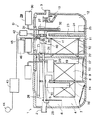
図1及び図2に示すように、本発明の1つの実施の形態に係る脱リン処理装置Dは、流量調整機能のある汚水処理装置としての小型合併処理浄化槽1に組み込まれて用いられている。
【0020】
この浄化槽1の内部は、屎尿廃水と生活廃水との混合した汚水が流入する流入管2の側から、汚水処理ずみの水を外部へ放流する放流管3の側にかけて、汚水浄化処理の工程順に応じて複数の槽が区画形成された槽構造にされている。
【0021】
4は流入管2側の最前部に区画形成された夾雑物除去槽である。この夾雑物除去槽4では、屎尿廃水や生活廃水の中に混入されており浄化処理できない夾雑物を沈殿分離させて除去する。
【0022】
夾雑物除去槽4の流入管2側には流入ガイド5が区画形成されている。この流入ガイド5と流入管2との間には、流入水を夾雑物除去槽4の下方へ向かって案内する角筒状あるいは円筒状の降流通路6が形成されている。
【0023】
また、夾雑物除去槽4には嫌気性微生物の濾床である嫌気濾床7が設けられており、その嫌気濾床7に微生物を棲息させることで嫌気処理を行うようにされている。嫌気濾床7は、流入水や逆洗廃水が一時的に流入した際の水流によって沈殿物が巻き上げられ浮遊物質となって次の槽へ流出するのを抑えて、次の槽の負荷を下げることができる。
【0024】
8は夾雑物除去槽4に隣接して区画形成された次の嫌気濾床槽である。この嫌気濾床槽8では、嫌気濾床9に嫌気性微生物を棲息させることで嫌気処理を行うようにされている。
【0025】
10は嫌気濾床槽8に隣接して区画形成された次の生物膜濾過槽である。この生物膜濾過槽10には好気性微生物の濾床である好気濾床11が設けられており、その好気濾床11に好気性微生物を棲息させることで好気処理を行うようにされている。
【0026】
12は生物膜濾過槽11に隣接して区画形成された次の処理水槽である。この処理水槽12では、生物膜濾過槽11で好気処理され、濾過されて移流してきた処理水を静置貯蔵する。
【0027】
13は処理水槽12の上部に区画形成された消毒槽である。この消毒槽13は通常、処理水槽12で処理された後の上澄み水を消毒処理して、放流管3から外部へ排出するようにされている。
【0028】
夾雑物除去槽4と嫌気濾床槽8とは垂直な隔壁14で仕切られている。この隔壁14の上部には、隔壁14を貫通する移流口15が開口形成されている。そして、この移流口15に角筒状あるいは円筒状の移流管16が嵌められている。この移流管16は、その下端が夾雑物処理槽4の嫌気濾床7の下部に位置しており、清掃口を兼ねている。
【0029】
嫌気濾床槽8と次の生物膜濾過槽10とは中間隔壁17で仕切られている。この中間隔壁17の嫌気濾床槽8側には上昇流通路18が固定状に設けられている。夾雑物除去槽4から移流管16を通って嫌気濾床槽8へ移流してきた汚水は、嫌気濾床9を下降流で通過した後、上昇流通路18を通って上昇する。
【0030】
上昇流通路18の上部には定量ポンプ19の取水口20が設けられている。定量ポンプ19は嫌気濾床槽8から生物膜濾過槽10へ一定量の汚水を移送する。すなわち、汚水は取水口20から定量ポンプ19内に取り込まれて次の生物膜濾過槽10へ一定量送り込まれる。
【0031】
嫌気濾床槽8における嫌気濾床9で、ある程度の浮遊物質(SS)が捕捉される。捕捉されたSSは、徐々に嫌気分解されて溶解性のものになっていったり、嫌気濾床槽8の底に汚泥として貯留されたりする。また、嫌気濾床9では有機性の窒素がアンモニア性の窒素に嫌気分解される。
【0032】
生物膜濾過槽10の底部付近には、散気装置21の散気管22が横設状態に配されている。この散気装置21は、その散気管22から空気を吹き出すことで、生物膜濾過槽10の好気濾床11に棲息する好気性微生物に対する酸素供給機能を果す。
【0033】
生物膜濾過槽10における好気濾床11には濾材が配置してあり、この濾材に付着した微生物が、BOD成分等を分解したりSS化したりして濾材に捕捉する。生物膜濾過槽10は物理的な濾過作用も有しており、ここでもSSを捕捉する。また、生物膜濾過槽10では、窒素を硝酸に変える硝酸菌や亜硝酸菌の働きでアンモニア性窒素を硝酸性窒素に変える。
【0034】
生物膜濾過槽10と次の処理水槽12との間には隔壁23が設けられている。そして、この隔壁23を通して生物膜濾過槽10と処理水槽12とをつなぐU字管24が設けられている。このU字管24は、隔壁23の上部で屈曲されており、生物膜濾過槽10の底部寄り箇所と処理水槽12の底部とに開口している。
【0035】
処理水槽12の底部には、U字管24の開口部に連なるポンプ25が設置されている。そして、好気濾床11にSSが溜まり生物膜濾過槽10の洗浄が必要なときに、このポンプ25を作動させて処理水槽12に溜まった処理水を通常の流れとは逆に生物膜濾過槽10へ流すことで、好気濾床11を洗う。その逆洗水は生物膜濾過槽10から夾雑物除去槽7へ返送管を通じて返送される。
【0036】
処理水槽12の上部から夾雑物除去槽4の上部にかけて、処理水中の上澄み水を常時返送するための循環路26が設けられている。この循環路26には、処理水槽12から水の流れの順に、分水計量装置27、脱リン処理装置D、夾雑物除去槽への流入口28が設けられている。
【0037】
処理水槽12における処理水中の上澄み水は、エアリフトポンプ29を用いて処理水槽12の中間部から汲み上げられ、分水計量装置27、脱リン処理装置Dを経た後に、循環路26を介して夾雑物除去槽4の降流通路6の上部に戻される。エアリフトポンプ29は槽外のブロア30、エアリフト用給気管31、リフト管32から構成されている。
【0038】
槽外のブロア30からエアリフト用給気管31へ給気すると、処理水槽12の処理水は、リフト管32の下端開口部から引き込まれ、そのエアリフト作用によって管内を上昇し、分水計量装置27に送られる。
【0039】
分水計量装置27は処理水槽12の上部に設置され、正・背面板部と左右の側面板部と底板部とから矩形箱状の有底構造に一体形成されている。この箱内部は、流入室33と、分水室35・36と、両者の間の中間室34とに区画されている。
【0040】
流入室33には、エアリフトポンプ29からの流入水を流入させる流入管が設置されている。流入室33と中間室34とは、下部側を連通可能に開口形成した隔壁で仕切られ、流入室33に流入した処理水を潜流させて中間室34へ移流させるようにしている。
【0041】
分水室35・36は、第1分水室35と第2分水室36との2室に区分されている。そして、第1分水室35と中間室34との隔壁は、下端が底板に固定され上端がV字状に開放されている。第2分水室36と中間室34との隔壁は、下端が底板に固定され上端が凹字状に開放されている。そして、この凹字状に開放された隔壁には、その開放寸法を調節することのできる溢流堰板が取り付けられている。
【0042】
第1分水室35には、処理水を循環路26へ流出させるための流出管37が接続され、第2分水室36には、処理水を生物膜濾過槽10へ流出させるための流出管38が接続されている。したがって、流入室33に流入した処理水は、中間室34を経て、溢流堰板の高さ調整により、2つの分水室35・36で循環路26と生物膜濾過槽10とへ分水される。
【0043】
脱リン処理装置Dは、溶出槽39と、この溶出槽39に配された長方形板状の4組の鉄電極40・41と、これらの電極40・41間に電流を印加する直流電源42と、制御部43と、スイッチ44とを備えている。なお、電極40・41は陽極も陰極もともに鉄が用いられている。
【0044】
溶出槽39には、流出管37から流出した処理水が溜められる。4組の鉄電極40・41は、電気分解によりリン酸と反応する鉄イオンを溶出させる。制御部43は、これらの電極40・41間に印加する電流の制御を行うことにより溶出槽39での前記イオンの溶出量を制御する。
【0045】
溶出槽39は、生物膜濾過槽10の上部に設けられており、正・背面板部と左右の側面板部と底板部とから矩形箱状の有底構造に一体形成されている。正・背面板部にはそれぞれ、流入管部と流出管部が設けられている。
【0046】
図3にも示すように、溶出槽39には、4つの電極ユニット47と、これらの電極ユニット47にばっ気を行うためのばっ気管45と、このばっ気管45に給気するために槽外に配置されたブロア46とが取り付けられている。各電極ユニット47は、一組の電極40・41を所定間隔で対向状に配して、それらの上部を保持具48に固定してなるものである。
【0047】
図4に基づいてより詳しく説明すると、保持具48は、一組の電極40・41及び端子が取り付けられた下部保持具49と、この下部保持具49の上に被せ嵌められる上部保持具50とからなる。下部保持具49と上部保持具50とは、下部保持具49に設けられた2つの嵌合孔49aに、上部保持具50に設けられた2つの嵌合爪50aがそれぞれ嵌められて一体化される。
【0048】
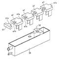
各電極ユニット47の保持具48には、連結用凸部47aと連結用凹部47bとが設けられている。そして、図5及び図6に示すように、1つの電極ユニット47の凸部47aを隣りの1つの電極ユニット47の凹部47bに嵌めるとともに、一端側の電極ユニット47の凹部47bに凸状部材51の凸部51aを、他端側の電極ユニット47の凸部47aを凹状部材52の凹部52aに嵌めて溶出槽39にセットすることで、所望数の電極ユニット47の列を得ることができる。
【0049】
この溶出槽39における鉄の溶解は、不動態化(鉄が溶解しなくなる現象)を防ぐために、直流極性反転(DC−PR)方式で定電流電気分解法を用いて行っている。
【0050】
不動態化は陽極で起こり、ある種の酸化被膜が電極表面を覆うために起こると考えられているが、陰極では水素ガスが発生して電極表面を常に洗浄しているので、極性反転により対向両電極とも陰極になる機会を与えることにより、不動態化を起こりにくくできる。また、極性反転するので、両電極が均等に溶けるようになり電極を同時交換できる。この極性反転時間は1時間以上に設定するのが好ましい。これが短かすぎると、例えば5秒間隔で極性を切り換えると、電流を流しても鉄は溶解しなくなる。
【0051】
また、電気分解はDC−パルス定電流電気分解法で行ってもよい。この場合は一方(陰極)を銀や白金などの金属からなる不溶性電極として、もう一方(陽極)に鉄やアルミニウムの電極を配置する。不動態化の対策としては、時々高い電圧を印加するパルス衝撃による。
【0052】
電極ユニット47の列の下部に横設されたばっ気管45には槽外に配置されたブロア46から空気が供給されており、処理水中の溶存酸素が減っていくのを補うようになっている。
【0053】
すなわち、鉄が溶解すると2価の鉄イオンFe2+としてイオン化するが、オルトリン酸PO4 3-と反応するためには3価の鉄イオンFe3+になる必要がある。Fe2+からFe3+にするには酸化することが必要で、これは処理水中の溶存酸素を利用して行われる。溶存酸素がなくなれば、溶け出した鉄はFe2+のままであり、オルトリン酸PO4 3-と反応しなくなる。そこで、ばっ気管45からのばっ気を行うことで処理水中の溶存酸素を補うようにしている。
【0054】
溶出槽39では電極40・41から鉄イオンFe2+が溶解し、ばっ気管45により酸素を処理水中に供給する。Fe2+は、溶存酸素を利用して酸化処理されてFe3+になりながら夾雑物除去槽4へ送られ、オルトリン酸PO4 3-と反応して難溶性のリン酸鉄塩Fe(OH)x (PO4 )y となる。そして、このリン酸鉄塩Fe(OH)x (PO4 )y は、夾雑物除去槽4に存在するSS分を核にして凝集し、大きなフロックになり、沈殿して槽底部に堆積する。
【0055】
夾雑物除去槽4の槽底部に堆積した、リン酸鉄を含む夾雑物は、夾雑物除去槽4の嫌気濾床7のない部分から、バキュームカーにより定期的に(通常、1年当たり1回程度の割合で)汲み出される。夾雑物除去槽4の嫌気濾床7を構成する濾材は、移流管16を利用して内側から、嫌気濾床7のない部分を利用して外側から、洗うことができる。
【0056】
DC−PR電気分解などの電源42は槽外に設置されている。この電源42は制御部43により制御される。電源42と電極40・41との間には、図7に示すように、電極間電圧の変化を検知する検知部としての電圧センサ53が並列に配されている。なお、鉄イオンの溶出は理論上ファラデーの法則に従い、電流によって決まるため、電極に定電流を印加している。
【0057】
電解を行って鉄を溶出させていくと、電極40・41は溶けて徐々に小さくなっていくが、電極40・41に定電流を印加しているので、鉄の溶出に伴って電極40・41に印加される電圧は上昇する。
【0058】
この電圧上昇により電極間電圧が所定値になったことを電圧センサ53が検知すると、制御部43が槽外に設けられた視覚的報知部としての電極消耗報知ランプ(図示略)を点灯させて、電極40・41の交換時期を報知するとともに、電圧の上昇を防止するため、電極40・41に定電圧を印加する。
【0059】
このときの電圧の所定値を20V程度に設定しておけば、人体に対して感電などの危険が少なくなる。
【0060】
使用者が管理者にメンテナンスの依頼をしてから電極交換をするまでの間は、鉄電極40・41に定電圧を印加しており、鉄電極40・41の表面積が溶解によって減少するにつれて、そこに流れる電流が減少し、ファラデーの法則に沿って鉄の溶出量が減少するが、リン除去性能低下を抑制することができる。
【0061】
また、電極間電圧が20Vになれば、電極消耗報知ランプを点灯させて定電流印加を継続し、25Vまで上昇すれば25Vより低い定電圧を電極40・41に印加する構成としてもよい。さらに、電極間電圧が20Vになれば、電極消耗報知ランプを点灯させて定電流印加を継続し、25Vまで上昇すれば電源をOFFにする構成としてもよい。
【0062】
以上のように構成された脱リン処理装置Dを用いて所定の直流定電流電気分解を行ったときの、電極40・41の端子間電圧(電極間電圧)(V)と電極消費率(電極の表面積の減少割合)(%)との関係を図8に示す。
【0063】
図8からわかるように、端子間電圧が20Vまで上昇したときの電極消費率は約62.5%であり、端子間電圧が25Vまで上昇したときの電極消費率は約71%であった。
【0064】
次に、この脱リン処理装置Dに付加されるのが好ましい要素及びその機能について説明する。
【0065】
浄化槽の選定に関する現行規則では、浄化槽の大きさは実際に流入する水量・水質によって決めるられるのではなく、「建築物の用途別による屎尿浄化槽の処理対象人員算定基準=JIS A 3302」によって決められる。
【0066】
すなわち、浄化槽の処理対象人員算定基準は

このJISの人員算定方法では実態にそぐわない面が多い。例えば、建物の床面積が220m2を超える場合には、実際は2人しか住んでいなくとも10人槽が必要となる。
【0068】
このような場合に、JISの算定基準で求めた人員に応じて鉄を溶出させるようにすると、必要量以上の鉄が溶出する。鉄は、リン酸と反応する他に水酸基OH-と反応して水酸化第二鉄の形でも難溶性の塩になり、汚泥として堆積される。このため、鉄を過剰に溶かすと、この水酸化第二鉄の汚泥が増えて汚泥引き抜き回数(浄化槽清掃回数)が増加する等の問題を引き起こすことになったり、鉄溶出のために必要以上の電気量を消費することになったりして、不経済になる。
【0069】
そこで、実際の使用人数に合わせて鉄の溶出量を制御するスイッチを設けるようにする。これにより、鉄が過剰に溶出して水酸化第二鉄の汚泥量が増えて汚泥引き抜き回数が増加するのを防止するとともに、電気代の節約を図ることができる。また、合併処理浄化槽1に流入する汚水の流入量に応じて鉄の溶出量を自動調整するようにしてもよい。
【0070】
【発明の効果】
請求項1の発明によれば、電気分解の進行に伴う電極の消耗状態を定電流電気分解による電極間電圧の変化で検知する検知部が設けられているので、電極の取り換えのために電極の消耗度が簡単に判るという効果を奏する。
【0071】
請求項2の発明によれば、電極の交換時期を報知するための報知部をさらに備え、検知部により検知した電極間電圧が所定値になると報知部が前記報知を行うので、使用者に電極の交換時機を知らせることができる。
【0072】
請求項3の発明によれば、報知部が視覚的報知部及び聴覚的報知部のうちの少なくとも一方からなるので、請求項2の発明が奏する前記効果を簡単で安価な部材により確保することができる。
【0073】
請求項4の発明によれば、制御部が検知部により検知した電極間電圧を所定電圧未満にするような制御を行うので、請求項1の発明が奏する前記効果に加えて、感電のおそれを防止することができる。
【0074】
請求項5の発明によれば、電極間電圧が上昇して所定電圧になると制御部が電源OFFを指示するので、感電のおそれを防止することができる。
【0075】
請求項6の発明によれば、電極間電圧が上昇して所定電圧になると制御部が定電流電気分解に代えて定電圧電気分解を行うよう指示するので、請求項4の発明が奏する前記効果に加えて、定電流電気分解を止め電極間電圧を所定値に保って電気分解をすることで脱リン性能低下を抑制することができる。
【図面の簡単な説明】
【図1】 本発明の1つの実施の態様に係る脱リン処理装置が組み込まれた小型合併処理浄化槽の垂直縦断面図である。
【図2】図1の小型合併処理浄化槽の水平断面図である。
【図3】図1の脱リン処理装置の一部を拡大した垂直横断面図である。
【図4】図1の脱リン処理装置の一部を構成する電極ユニットの分解斜視図である。
【図5】図4の電極ユニットを4つ、溶出槽にセットする途中の状態を示す斜視図である。
【図6】図4の電極ユニットを4つ、溶出槽にセットした状態を示す斜視図である。
【図7】図1の脱リン処理装置の電気回路図である。
【図8】図1の脱リン処理装置を用いて所定の直流定電流電気分解を行ったときの、電極の端子間電圧(V)と電極消費率(%)との関係を示すグラフである。
【符号の説明】
39 溶出槽
40 電極
41 電極
42 電源
43 制御部
44 スイッチ
47 電極ユニット
53 電圧センサ(検知部)[0001]
BACKGROUND OF THE INVENTION
The present invention relates to a sewage treatment apparatus, and more particularly to a sewage treatment apparatus such as a combined treatment septic tank for removing phosphoric acid from sewage mixed with manure wastewater and domestic wastewater.
[0002]
[Prior art]
As this kind of sewage treatment apparatus, the one disclosed in JP-A-7-108296 (
[0003]
As the iron dissolving apparatus here, a fiber or cotton-like iron material is used as an electrode, and a DC or AC voltage of 1 to 100 V is applied, and the elution amount of iron ions is adjusted by the applied voltage. It has been.
[0004]
[Problems to be solved by the invention]
If iron is eluted, iron is consumed, so it is necessary to replenish iron. However, since the sewage treatment equipment (septic tank) is mostly buried outdoors in the ground, go out outdoors to check for the presence of iron and pull the iron electrode from the septic tank to the ground or look inside the septic tank. It has to be troublesome. However, if the inspection is not carried out, the iron as an electrode in the iron dissolving apparatus is lost and phosphoric acid is not removed, so that there is a problem that the septic tank does not fulfill its original purpose of removing phosphorus.
[0005]
The present invention has been made in view of such circumstances, and an object of the present invention is to provide a sewage treatment apparatus that stably dissolves an electrode and that can easily determine the degree of electrode wear for electrode replacement. To do.
[0006]
[Means for Solving the Problems]
According to one aspect of the present invention, the electrode includes at least a pair of electrodes for eluting iron ions or aluminum ions for removing phosphoric acid in sewage , and a power supply means for applying a constant current between the electrodes. There is provided a sewage treatment apparatus characterized in that a detection unit for detecting a consumption state of an electrode from an inter-voltage change is provided.
[0007]
At least a pair of electrodes are arranged, and iron ions or aluminum ions are eluted by electrolysis. These ions are reacted with phosphoric acid in wastewater (orthophosphoric acid), a poorly soluble phosphorus compound (Fe (OH) x (PO 4) y or Al (OH) x (PO 4 ) y) aggregation And precipitate. A current for electrolysis is applied between the electrodes.
[0008]
The pair of electrodes, for example, are both constructed from one of iron and aluminum, or one from one of iron and aluminum and the other from an insoluble metal. In the former case, it is possible to prevent the electrode from being passivated by preventing the ion elution from the electrode by reversing the polarity of the electrode as desired. In the latter case, an electrode composed of one of iron and aluminum is used as an anode, and an electrode composed of an insoluble metal is used as a cathode. Here, as an electrode comprised from the insoluble metal, there exist electrodes, such as silver and platinum, for example.
[0009]
The dephosphorization processing apparatus according to the present invention is further provided with a characteristic detector. This detection unit detects the consumption state of the electrode as the electrolysis progresses from the change in the interelectrode voltage under a constant current, in other words, from the change in the interelectrode voltage due to constant current electrolysis.
[0010]
That is, as the electrolysis progresses, ions continue to elute from the electrode, and as a result, the surface area of the electrode gradually decreases. At this time, the electrolysis is performed with a constant current in order to make the amount of eluted ions per unit time constant. For this reason, when the electrode is consumed and its surface area decreases, the voltage between the electrodes gradually increases.
[0011]
When the surface area of the electrode decreases to a certain value, the voltage between the electrodes rises to a considerably high value, which may cause an electric shock, and there is a possibility that a necessary amount of ion elution will not occur. Therefore, by providing a detection unit, the consumption state of the electrode is detected from the change in the voltage between the electrodes due to constant current electrolysis, that is, the degree of increase in the voltage between the electrodes. For example, a voltage sensor connected between both electrodes is used as the detection unit.
[0012]
The dephosphorization processing apparatus according to the present invention preferably further includes a notifying unit for notifying the replacement timing of the electrodes, so that the notifying unit performs the notification when the voltage between the electrodes detected by the detecting unit reaches a predetermined value. It is configured.
[0013]
With this configuration, the detection unit detects that the voltage between the electrodes has reached a predetermined value, and the detection result is input to a control unit provided as desired. An instruction for notifying the replacement time is output to inform the user. An administrator (a contractor, a maintenance manager, etc.) who has received a communication from the user of the sewage treatment apparatus can replace the electrodes to continue appropriate ion elution.
[0014]
The notification unit includes, for example, both or one of a visual notification unit such as an LED lamp and an auditory notification unit such as a buzzer.
[0015]
An example of the control by the control unit is to perform control such that the interelectrode voltage detected by the detection unit is less than 25 V (predetermined voltage). As described above, when the surface area of the electrode is consumed to a certain value as the constant current electrolysis progresses, the voltage between the electrodes rises to a considerably high value, and there is a risk of electric shock, and the required amount of ions is eluted. May not occur. In view of this, when the voltage between the electrodes is 25 V or more, it is considered that these fears occur, and the control unit controls the voltage to be less than 25 V.
[0016]
For example, when the voltage between the electrodes rises to 25 V or more, the control unit can prevent the electric shock by instructing to turn off the power. In addition, when the voltage between the electrodes rises to around 25V, an instruction is given to perform constant voltage electrolysis instead of constant current electrolysis, and the constant current electrolysis is stopped and the electrode voltage is maintained at a predetermined value less than 25V. By doing so, a dephosphorization performance fall can be suppressed.
[0017]
According to another aspect of the present invention, there is provided a sewage treatment apparatus incorporating the various dephosphorization treatment apparatuses. For example, a dephosphorization processing device is arranged in the upper part of the biofilm filtration tank (bacterial tank) of the merged processing septic tank or the next processing water tank (precipitation tank) adjacent to this, and the contaminant removal tank (first) There is provided a combined treatment septic tank configured to remove phosphoric acid from the treated water returned to the anaerobic filter bed tank).
[0018]
DETAILED DESCRIPTION OF THE INVENTION
Hereinafter, one embodiment of the present invention will be described with reference to the drawings. Note that the present invention is not limited thereby.
[0019]
As shown in FIGS. 1 and 2, a dephosphorization processing device D according to one embodiment of the present invention is incorporated and used in a small combined treatment septic tank 1 as a sewage treatment device having a flow rate adjusting function. .
[0020]
The inside of the septic tank 1 is arranged in the order of the sewage purification process from the side of the
[0021]
[0022]
An
[0023]
The
[0024]
[0025]
[0026]
[0027]
[0028]
The
[0029]
The anaerobic
[0030]
A
[0031]
A certain amount of suspended matter (SS) is trapped in the
[0032]
In the vicinity of the bottom of the
[0033]
A filter medium is disposed in the
[0034]
A
[0035]
A
[0036]
A
[0037]
The supernatant water of the treated water in the treated
[0038]
When air is supplied from the
[0039]
The
[0040]
The
[0041]
The
[0042]
The
[0043]
The dephosphorization processing apparatus D includes an
[0044]
In the
[0045]
The
[0046]
As shown in FIG. 3, the
[0047]
Referring to FIG. 4 in more detail, the
[0048]
The
[0049]
The dissolution of iron in the
[0050]
Passivation occurs at the anode, and it is thought that some kind of oxide film covers the electrode surface, but at the cathode, hydrogen gas is generated and the electrode surface is constantly washed. Passivation can be made difficult to occur by giving both electrodes the opportunity to become cathodes. Further, since the polarity is reversed, both electrodes can be melted evenly and the electrodes can be exchanged simultaneously. The polarity inversion time is preferably set to 1 hour or longer. If this is too short, for example, if the polarity is switched at intervals of 5 seconds, the iron will not dissolve even if a current is passed.
[0051]
Electrolysis may be performed by a DC-pulse constant current electrolysis method. In this case, one (cathode) is an insoluble electrode made of metal such as silver or platinum, and the other (anode) is an iron or aluminum electrode. As a countermeasure for passivation, pulse shock is sometimes applied to apply a high voltage.
[0052]
Air is supplied from a
[0053]
That is, when iron is dissolved, it is ionized as a divalent iron ion Fe 2+ , but it needs to be a trivalent iron ion Fe 3+ in order to react with orthophosphoric acid PO 4 3− . To convert from Fe 2+ to Fe 3+ , it is necessary to oxidize, and this is performed using dissolved oxygen in the treated water. When the dissolved oxygen disappears, the dissolved iron remains Fe 2+ and does not react with the orthophosphoric acid PO 4 3− . Therefore, the aeration from the
[0054]
In the
[0055]
Contaminants containing iron phosphate deposited on the bottom of the
[0056]
A
[0057]
When iron is eluted by electrolysis, the
[0058]
When the
[0059]
If the predetermined value of the voltage at this time is set to about 20 V, the risk of electric shock or the like is reduced for the human body.
[0060]
From when the user requests maintenance to the administrator until the electrode is replaced, a constant voltage is applied to the
[0061]
Further, when the voltage between the electrodes becomes 20V, the electrode consumption notification lamp is turned on to continue the constant current application, and when the voltage rises to 25V, a constant voltage lower than 25V may be applied to the
[0062]
The voltage between terminals (voltage between electrodes) (V) and the electrode consumption rate (electrodes) of the
[0063]
As can be seen from FIG. 8, the electrode consumption rate when the inter-terminal voltage increased to 20V was about 62.5%, and the electrode consumption rate when the inter-terminal voltage increased to 25V was about 71%.
[0064]
Next, elements and functions that are preferably added to the dephosphorization processing apparatus D will be described.
[0065]
According to the current rules regarding the selection of septic tanks, the size of the septic tank is not determined by the actual amount of water flowing in or the quality of water, but is determined by the “Calculation criteria for human waste septic tank treatment by type of building = JIS A 3302”. .
[0066]
In other words, the standard for calculating the number of people subject to septic tank processing is
This JIS personnel calculation method has many aspects that do not match the actual situation. For example, if the floor area of a building exceeds 220 m 2 , a 10-person tank is required even if only two people actually live.
[0068]
In such a case, if iron is eluted according to the personnel determined by the calculation standard of JIS, more iron than necessary is eluted. In addition to reacting with phosphoric acid, iron reacts with hydroxyl OH - to form a sparingly soluble salt in the form of ferric hydroxide, and is deposited as sludge. For this reason, if iron is dissolved excessively, this ferric hydroxide sludge increases, causing problems such as an increase in the number of sludge extractions (the number of times the septic tank is cleaned), or more than necessary for elution of iron. It will be uneconomical because it consumes electricity.
[0069]
Therefore, a switch for controlling the iron elution amount according to the actual number of users is provided. As a result, it is possible to prevent excessive elution of iron and increase the amount of ferric hydroxide sludge and increase the number of sludge extractions, and save electricity costs. Moreover, you may make it adjust the elution amount of iron automatically according to the inflow amount of the sewage which flows in into the merger processing septic tank 1.
[0070]
【The invention's effect】
According to the first aspect of the present invention, there is provided the detection unit for detecting the consumption state of the electrode as the electrolysis proceeds by the change in the voltage between the electrodes due to the constant current electrolysis. There is an effect that the degree of wear can be easily understood.
[0071]
According to the second aspect of the present invention, the apparatus further includes a notifying unit for notifying the replacement time of the electrode, and the notifying unit notifies the user when the voltage between the electrodes detected by the detecting unit reaches a predetermined value. You can be informed of when to change.
[0072]
According to the invention of
[0073]
According to the invention of
[0074]
According to the invention of
[0075]
According to the invention of
[Brief description of the drawings]
FIG. 1 is a vertical longitudinal sectional view of a small merged treatment septic tank incorporating a dephosphorization processing apparatus according to one embodiment of the present invention.
2 is a horizontal cross-sectional view of the small merged treatment septic tank of FIG. 1;
FIG. 3 is an enlarged vertical cross-sectional view of a part of the dephosphorization processing apparatus of FIG. 1;
4 is an exploded perspective view of an electrode unit constituting a part of the dephosphorization processing apparatus of FIG. 1. FIG.
FIG. 5 is a perspective view showing a state in the middle of setting four electrode units of FIG. 4 in the elution tank.
6 is a perspective view showing a state where four electrode units of FIG. 4 are set in an elution tank. FIG.
FIG. 7 is an electric circuit diagram of the dephosphorization processing apparatus of FIG. 1;
8 is a graph showing the relationship between electrode terminal voltage (V) and electrode consumption rate (%) when predetermined DC constant current electrolysis is performed using the dephosphorization apparatus of FIG. 1. FIG. .
[Explanation of symbols]
39
Claims (5)
電極間電圧の変化から電極の消耗状態を検知する検知部が設けられているとともに、
制御部をさらに備え、その制御部が、検知部により検知した電極間電圧を所定電圧未満にするような制御を行うことを特徴とする汚水処理装置。Comprising at least a pair of electrodes for eluting iron ions or aluminum ions for removing phosphoric acid in sewage, and a power feeding means for applying a constant current between the electrodes,
A detection unit that detects the consumption state of the electrode from the change in the voltage between the electrodes is provided ,
A sewage treatment apparatus , further comprising a control unit, wherein the control unit performs control such that an interelectrode voltage detected by the detection unit is less than a predetermined voltage .
Priority Applications (4)
| Application Number | Priority Date | Filing Date | Title |
|---|---|---|---|
| JP06508697A JP3954683B2 (en) | 1997-03-18 | 1997-03-18 | Sewage treatment equipment |
| TW87102671A TW425377B (en) | 1997-03-18 | 1998-02-23 | Waste water treatment equipment |
| CN98100883A CN1120809C (en) | 1997-03-18 | 1998-03-04 | Wastewater treating apparatus |
| KR1019980008025A KR100253757B1 (en) | 1997-03-18 | 1998-03-11 | Sewage treatment apparatus |
Applications Claiming Priority (1)
| Application Number | Priority Date | Filing Date | Title |
|---|---|---|---|
| JP06508697A JP3954683B2 (en) | 1997-03-18 | 1997-03-18 | Sewage treatment equipment |
Publications (2)
| Publication Number | Publication Date |
|---|---|
| JPH10258288A JPH10258288A (en) | 1998-09-29 |
| JP3954683B2 true JP3954683B2 (en) | 2007-08-08 |
Family
ID=13276787
Family Applications (1)
| Application Number | Title | Priority Date | Filing Date |
|---|---|---|---|
| JP06508697A Expired - Lifetime JP3954683B2 (en) | 1997-03-18 | 1997-03-18 | Sewage treatment equipment |
Country Status (4)
| Country | Link |
|---|---|
| JP (1) | JP3954683B2 (en) |
| KR (1) | KR100253757B1 (en) |
| CN (1) | CN1120809C (en) |
| TW (1) | TW425377B (en) |
Families Citing this family (10)
| Publication number | Priority date | Publication date | Assignee | Title |
|---|---|---|---|---|
| KR100372554B1 (en) * | 1999-07-13 | 2003-03-07 | 황재석 | Improved apparatus for disposal of sewage, waste water and night soil of livestock by constant-current electrolytic analysis |
| JP4421049B2 (en) * | 2000-02-02 | 2010-02-24 | 三洋電機株式会社 | Drain electrode holder |
| JP3685689B2 (en) * | 2000-07-31 | 2005-08-24 | 三洋電機株式会社 | Sewage treatment device and detection method of exchange time of ion supply electrode pair |
| JP4520053B2 (en) * | 2001-01-23 | 2010-08-04 | 三洋電機株式会社 | Sewage treatment equipment |
| JP4520054B2 (en) * | 2001-01-23 | 2010-08-04 | 三洋電機株式会社 | Installation method of sewage treatment equipment |
| JP4548963B2 (en) * | 2001-03-29 | 2010-09-22 | 三洋電機株式会社 | Sewage treatment electrolyzer |
| CN111056710B (en) * | 2019-12-28 | 2022-06-14 | 西安建筑科技大学 | Sewage advanced treatment and resource recovery system and method for anaerobic ectopic electric release iron membrane bioreactor |
| TWI722800B (en) * | 2020-02-20 | 2021-03-21 | 彭梓育 | Aeration tube |
| EP3882219A1 (en) * | 2020-03-19 | 2021-09-22 | Europhat Sverige AB | Electrolysis phosphate precipitation module |
| CN115784529B (en) * | 2022-12-23 | 2023-08-18 | 浙江海拓环境技术有限公司 | Recycling treatment method of iron phosphate production wastewater |
-
1997
- 1997-03-18 JP JP06508697A patent/JP3954683B2/en not_active Expired - Lifetime
-
1998
- 1998-02-23 TW TW87102671A patent/TW425377B/en not_active IP Right Cessation
- 1998-03-04 CN CN98100883A patent/CN1120809C/en not_active Expired - Fee Related
- 1998-03-11 KR KR1019980008025A patent/KR100253757B1/en not_active IP Right Cessation
Also Published As
| Publication number | Publication date |
|---|---|
| JPH10258288A (en) | 1998-09-29 |
| KR100253757B1 (en) | 2000-04-15 |
| CN1120809C (en) | 2003-09-10 |
| CN1193608A (en) | 1998-09-23 |
| TW425377B (en) | 2001-03-11 |
| KR19980080108A (en) | 1998-11-25 |
Similar Documents
| Publication | Publication Date | Title |
|---|---|---|
| JP3954683B2 (en) | Sewage treatment equipment | |
| JP3696001B2 (en) | Sewage treatment equipment | |
| JP3485820B2 (en) | Sewage treatment equipment | |
| JP3883645B2 (en) | Dephosphorization processing equipment | |
| JP3802185B2 (en) | Sewage treatment equipment | |
| JPH10263586A (en) | Sewage treating device | |
| JP3802184B2 (en) | Sewage treatment equipment | |
| JPH10192869A (en) | Wastewater treatment apparatus | |
| JP3802186B2 (en) | Sewage treatment equipment | |
| JP4520054B2 (en) | Installation method of sewage treatment equipment | |
| JPH10258287A (en) | Waste water treatment apparatus | |
| JP4026920B2 (en) | Sewage treatment equipment | |
| JP2001047051A (en) | Water treatment device | |
| JP3895860B2 (en) | Sewage treatment equipment | |
| JP2002273448A (en) | Sewage treatment equipment | |
| JP3948823B2 (en) | Sewage treatment equipment | |
| JPH11188365A (en) | Sewage treatment apparatus | |
| JPH11104663A (en) | Sewage treatment apparatus | |
| JP3819528B2 (en) | Sewage treatment equipment | |
| JP2000317477A (en) | Sewage treating device | |
| JPH11128926A (en) | Sewage treatment apparatus | |
| JP3938996B2 (en) | Sewage treatment equipment | |
| JPH1190466A (en) | Sewage treatment apparatus | |
| JPH10258283A (en) | Waste water treatment device | |
| JPH11267682A (en) | Device of treating waste water containing phosphate ions |
Legal Events
| Date | Code | Title | Description |
|---|---|---|---|
| A977 | Report on retrieval |
Free format text: JAPANESE INTERMEDIATE CODE: A971007 Effective date: 20050628 |
|
| A131 | Notification of reasons for refusal |
Free format text: JAPANESE INTERMEDIATE CODE: A131 Effective date: 20050719 |
|
| A521 | Written amendment |
Free format text: JAPANESE INTERMEDIATE CODE: A523 Effective date: 20050914 |
|
| TRDD | Decision of grant or rejection written | ||
| A01 | Written decision to grant a patent or to grant a registration (utility model) |
Free format text: JAPANESE INTERMEDIATE CODE: A01 Effective date: 20070403 |
|
| A61 | First payment of annual fees (during grant procedure) |
Free format text: JAPANESE INTERMEDIATE CODE: A61 Effective date: 20070427 |
|
| FPAY | Renewal fee payment (event date is renewal date of database) |
Free format text: PAYMENT UNTIL: 20110511 Year of fee payment: 4 |
|
| FPAY | Renewal fee payment (event date is renewal date of database) |
Free format text: PAYMENT UNTIL: 20120511 Year of fee payment: 5 |
|
| FPAY | Renewal fee payment (event date is renewal date of database) |
Free format text: PAYMENT UNTIL: 20130511 Year of fee payment: 6 |
|
| FPAY | Renewal fee payment (event date is renewal date of database) |
Free format text: PAYMENT UNTIL: 20130511 Year of fee payment: 6 |
|
| EXPY | Cancellation because of completion of term |