【0001】
【発明の属する技術分野】
本発明は脱リン処理装置に関し、さらに詳しくは、合併処理浄化槽などの汚水処理装置に組み込まれ、屎尿廃水と生活廃水との混合した汚水からリン酸を除去するための脱リン処理装置に関する。
【0002】
【従来の技術】
この種の脱リン処理装置としては、特開平7−108296号(C02F 3/30)公報や特開平3−89998号(C02F 3/12,1/58,11/00)公報に開示されたものが知られている。
【0003】
前者は、嫌気濾床槽または沈殿分離槽と、ばっ気槽と、沈殿槽と、消毒槽とを、この順に配置した汚水処理装置において、ばっ気槽内の汚水をポンプによって汲み上げ、鉄溶解装置を介して嫌気濾床槽または沈殿分離槽に戻すようにしたものである。
【0004】
後者は、流量調整槽または沈殿分離槽などの液受槽と、生物処理槽と、汚泥濃縮槽とを備え、生物処理槽から液受槽に至る経路の少なくとも1箇所に、不溶性リン酸塩形成金属とそれよりも貴なる金属を導通状態に配置し、あるいは不溶性リン酸塩形成金属を一対以上配置するとともにそれらの間に電圧を印加して、電気化学的に不溶性リン酸形成金属イオンを液中(汚水中)に供給してリンを除去するようにした装置である。
【0005】
【発明が解決しようとする課題】
これらにあっては、汚水中のリン酸量が一定である場合でも汚水中に含まれる成分によってリン酸の除去率が大きく変動し、安定した脱リン処理を行うことが困難であるという問題がある。
【0006】
本発明者らは、その原因を種々検討し研究を重ねた結果、リン酸の除去率は汚水中のカルシウムイオンまたはマグネシウムイオンの濃度と密接な関係があることに気づいた。すなわち、汚水中のカルシウムイオンまたはマグネシウムイオンの濃度が一定濃度より低い場合には、前記鉄溶解装置で溶解した鉄イオンや前記不溶性リン酸形成金属イオンと汚水中のリン酸との反応が低下し、リン酸の除去率が大幅に低下することに気づいた。
【0007】
本発明は、このような実情に鑑みてなされたものであり、汚水中のカルシウムイオンまたはマグネシウムイオンの濃度を検出して、安定した脱リン処理を行う上でその検出濃度を1つの指標にすることができる脱リン除去装置を提供することを目的とする。
【0008】
【課題を解決するための手段】
本発明によれば、汚水中のリン酸を除去するための鉄イオンまたはアルミニウムイオンを溶出させる少なくとも一対の電極と、該電極間に供給する電流の制御を行うための制御部とを備え、汚水の前記電極に対して上流側に、汚水中のカルシウムイオン及び/またはマグネシウムイオンの濃度を検出するためのイオン濃度検出部が設けられていることを特徴とする脱リン処理装置が提供される。
【0009】
電極は、少なくとも一対配され、電気分解により鉄イオンまたはアルミニウムイオンを溶出する。これらのイオンは、汚水中のリン酸(オルトリン酸)と反応して、難溶性リン化合物(Fe(OH)x(PO4)yまたはAl(OH)x(PO4)y)となって凝集し沈殿する。電極間には電気分解のための電流が供給される。所望により設けられる制御部は、電極間に供給する電流の制御を行うことにより、前記イオンの溶出量を制御する。
【0010】
一対の電極は例えば、両方とも鉄及びアルミニウムのうちの1つから、または一方が鉄及びアルミニウムのうちの1つから他方が不溶性金属から構成される。前者の場合は、所望により電極の極性反転を行うことで、電極からのイオン溶出が起こらなくなる電極の不動態化を防止することができる。また、後者の場合は、鉄及びアルミニウムのうちの1つから構成された電極を陽極とし、不溶性金属から構成された電極を陰極とする。ここで、不溶性金属から構成された電極としては、例えば銀や白金などの電極がある。
【0011】
本発明に係る脱リン処理装置にはさらに、制御部とイオン濃度検出部が設けられている。
【0012】
制御部は少なくとも、電極間に供給する電流の制御を行うが、所望により他の制御も行うように構成されてもよい。
【0013】
イオン濃度検出部は汚水の電極に対して上流側に設けられ、汚水中のカルシウムイオン及び/またはマグネシウムイオンの濃度を検出する。このようなイオン濃度検出部としては例えば、汚水を一時的に溜めるための検出槽と、この検出槽に配されたカルシウムイオン選択性電極及び/またはマグネシウムイオン選択性電極とを構成要素としてフローセル型イオンセンサが用いられる。
【0014】
このイオン濃度検出部により検出されたカルシウムイオン及び/またはマグネシウムイオンの濃度は、例えば、安定した脱リン処理を行う上で1つの指標にされる。すなわち、制御部が、検出されたイオンの濃度に応じて、溶出槽の汚水中へ溶出させる鉄イオンまたはアルミニウムイオンの量を変化させる、というように利用される。
【0015】
制御部がそのように構成されている場合は、鉄イオンまたはアルミニウムイオンの溶出量を調節することができるので、カルシウムイオンまたはマグネシウムイオンの濃度に関係なく、リン酸の除去率を所望値にすることが可能になる。
【0016】
本発明に係る脱リン処理装置は、電極間電圧が25V以上になると制御部が電源OFFの指示を行うように構成されているのがいっそう好ましい。このように構成されている場合は、電極の表面積が消耗することに伴って電極間電圧がかなり高い値まで上昇して感電するというおそれを防止することができる。
【0017】
本発明に係る脱リン処理装置は、電極間電圧が25V以上になることで電源OFFになったことを報知するための報知部をさらに備えているのが好ましい。この報知部としては、LEDランプなどの視覚的報知部やブザーなどの聴覚的報知部の両方または一方からなる。
【0018】
このように構成されている場合は、制御部が報知部に電源OFFの報知をするような指示を出力して脱リン処理装置の使用者に知らせる。この使用者から連絡を受けた管理者(施工業者や保守管理業者など)が電極を点検しその取り換えや保守などをすることで、イオン溶出を継続することができる。
【0019】
【発明の実施の形態】
以下、本発明の1つの実施の形態を図面に基づいて説明する。なお、これによって本発明が限定されるものではない。
【0020】
図1に示すように、本発明の1つの実施の形態に係る脱リン処理装置Dは、小型合併処理浄化槽1に組み込まれて用いられている。
【0021】
この浄化槽1の内部は、屎尿廃水と生活廃水との混合した汚水が流入する流入管2の側から、汚水処理ずみの水を外部へ放流する放流管3の側にかけて、汚水浄化処理の工程順に応じて複数の槽が区画形成された槽構造にされている。
【0022】
4は流入管2側の最前部に区画形成された夾雑物除去槽である。この夾雑物除去槽4では、屎尿廃水や生活廃水の中に混入されていて浄化処理できない夾雑物を沈殿分離させて除去する。
【0023】
夾雑物除去槽4の流入管2側には流入ガイド5が区画形成されている。この流入ガイド5と流入管2との間には、流入水を夾雑物除去槽4の下方へ向かって案内する角筒状あるいは円筒状の降流通路6が形成されている。
【0024】
また、夾雑物除去槽4には嫌気性微生物の濾床である嫌気濾床7が設けられており、その嫌気濾床7に微生物を棲息させることで嫌気処理を行うようにされている。嫌気濾床7は、流入水や逆洗廃水が一時的に流入した際の水流によって沈殿物が巻き上げられて浮遊物質となって次の槽へ流出するのを抑えて、次の槽の負荷を下げることができる。
【0025】
8は夾雑物除去槽4に隣接して区画形成された次の嫌気濾床槽である。この嫌気濾床槽8では、嫌気濾床9に嫌気性微生物を棲息させることで嫌気処理を行うようにされている。
【0026】
10は嫌気濾床槽8に隣接して区画形成された次の好気濾床槽である。この好気濾床槽10には好気性微生物の濾床である好気濾床11が設けられており、その好気濾床11に好気性微生物を棲息させることで好気処理を行うようにされている。
【0027】
12は好気濾床槽10に隣接して区画形成された次の沈殿槽である。この沈殿槽12では、好気濾床槽10で好気処理され、濾過されて移流してきた処理水を静置貯蔵する。
【0028】
13は沈殿槽12の上部に区画形成された消毒槽である。この消毒槽13は通常、沈殿槽12で処理された後の上澄み水を消毒処理して、放流管3から外部へ排出するようにされている。
【0029】
夾雑物除去槽4と嫌気濾床槽8とは垂直な隔壁14で仕切られている。この隔壁14の上部には、隔壁14を貫通する移流口15が開口形成されている。そして、この移流口15に角筒状あるいは円筒状の移流管16が嵌められている。この移流管16は、その下端が夾雑物処理槽4の嫌気濾床7の下部に位置しており、清掃口を兼ねている。
【0030】
嫌気濾床槽8と次の好気濾床槽10とは中間隔壁17で仕切られている。この中間隔壁17の嫌気濾床槽8側には上昇流通路18が固定状に設けられている。夾雑物除去槽4から移流管16を通って嫌気濾床槽8へ移流してきた汚水は、嫌気濾床9を下降流で通過した後、上昇流通路18を通って上昇し、好気濾床槽10に流入する。
【0031】
嫌気濾床槽8における嫌気濾床9で、ある程度の浮遊物質(SS)が捕捉される。捕捉されたSSは、徐々に嫌気分解されて溶解性のものになっていったり、嫌気濾床槽8の底に汚泥として貯留されたりする。また、嫌気濾床9では有機性の窒素がアンモニア性の窒素に嫌気分解される。
【0032】
好気濾床槽10の底部付近には、散気装置21の散気管22が横設状態に配されている。この散気装置21は、その散気管22から空気を吹き出すことで、好気濾床槽10の好気濾床11に棲息する好気性微生物に対する酸素供給機能を果す。
【0033】
好気濾床槽10における好気濾床11には濾材が配置してあり、この濾材に付着した微生物が、BOD成分等を分解したりSS化したりして濾材に捕捉する。好気濾床槽10は物理的な濾過作用も有しており、ここでもSSを捕捉する。また、好気濾床槽10では、窒素を硝酸に変える硝酸菌や亜硝酸菌の働きでアンモニア性窒素を硝酸性窒素に変える。
【0034】
好気濾床槽10と次の沈殿槽12との間には隔壁23が設けられている。この隔壁23の下部には連通部24が設けられている。そして、この連通部24により、好気濾床槽10と沈殿槽12とは連通している。
【0035】
沈殿槽12では、連通部24を通して好気濾床槽10から流入した処理水が沈殿物と上澄み水とに分離される。沈殿槽12の底部は、そこに堆積した沈殿物を連通部24を通して好気濾床槽10へ戻すために、一定角度で傾斜した構造にされている。
【0036】
好気濾床槽10の底部と夾雑物除去槽4の上部とは、垂直部25aと水平部25bとからなるL字状の第1返送管25により連通している。第1返送管25の垂直部25aの内側には第1給気管31aが配されている。
【0037】
この第1給気管31aは、エアリフトポンプ29を構成する槽外のブロア30に、エアリフト用給気管31を介して接続されている。そして、ブロア30から供給された空気を第1給気管31aから吹き出すことにより、好気濾床槽10の底部に堆積した汚泥を第1返送管25に吸い込んで、夾雑物除去槽4へ戻すようになっている。
【0038】
一方、沈殿槽12における処理水中の上澄み水は、リフト管32の内部に配されかつ給気管31に連通する第2給気管31bから吹き出される空気によって、リフト管32から汲み上げられる。なお、第1給気管31aと第2給気管31bとは切換弁により、いずれか一方に切り換えできるようにされている。
【0039】
沈殿槽12の上部から夾雑物除去槽4の上部にかけて、処理水中の上澄み水を常時返送するための循環路26が設けられている。この循環路26には、沈殿槽12から水の流れの順に、分水計量装置27、脱リン処理装置D、夾雑物除去槽への流入口28が設けられている。そして、リフト管32から汲み上げられた前記上澄み水は、分水計量装置27、脱リン処理装置Dを経た後に、循環路26を介して夾雑物除去槽4の降流通路6の上部に戻される。
【0040】
分水計量装置27は沈殿槽12の上部に設置され、正・背面板部と左右の側面板部と底板部とから矩形箱状の有底構造に一体形成されている。この箱内部は、流入室と、分水室と、両者の間の中間室とに区画されている。
【0041】
流入室には、エアリフトポンプ29のリフト管32から汲み上げられた前記上澄み水を流入させる流入管が設置されている。流入室と中間室とは、下部側を連通可能に開口形成した隔壁で仕切られ、流入室に流入した処理水を潜流させて中間室へ移流させるようにしている。
【0042】
分水室は、第1分水室と第2分水室との2室に区分されている。そして、第1分水室と中間室との隔壁は、下端が底板に固定され上端がV字状に開放されている。第2分水室と中間室との隔壁は、下端が底板に固定され上端が凹字状に開放されている。そして、この凹字状に開放された隔壁には、その開放寸法を調節することのできる溢流堰板が取り付けられている。
【0043】
第1分水室には、処理水を循環路26へ流出させるための流出管37が接続され、第2分水室には、処理水を好気濾床槽10へ流出させるための流出管が接続されている。したがって、流入室に流入した処理水は、中間室を経て、溢流堰板の高さ調整により、2つの分水室で循環路26と好気濾床槽10とへ分水される。
【0044】
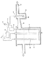
図2に拡大して示すように、脱リン処理装置Dは、溶出槽39と、この溶出槽39の内部にほぼ鉛直に配された長方形板状の1組(一対)の鉄電極40・41と、これらの電極40・41間に電流を供給する電気分解用の直流電源42と、制御部43と、スイッチ44と、ばっ気管45と、ばっ気用ブロア46とを備えている。なお、電極40・41は陽極も陰極もともに鉄が用いられている。
【0045】
溶出槽39には、流出管37から流出し、後述の検出槽49と流入管48とを通って流入した処理水が溜められる。1組の鉄電極40・41は、電気分解によりリン酸と反応する鉄イオンを溶出させる。制御部43は、これらの電極40・41間に供給する電流の制御を行うことにより溶出槽39での前記イオンの溶出量を制御する。制御部43はまた、電極40・41間の電圧が25V以上になると電源42のOFFとブロア46のOFFとを指示する。
【0046】
ばっ気管45は溶出槽39内に配されており、電極40・41にばっ気を行うことにより、電極40・41の表面を洗浄しあるいは溶出槽39における処理水の攪拌を行う。ばっ気用ブロア46は溶出槽39外に配されており、ばっ気管45に給気を行う。
【0047】
溶出槽39は、好気濾床槽10の上部に設けられており、正・背面板部と左右の側面板部と底板部とから矩形箱状の有底構造に一体形成されている。正・背面板部にはそれぞれ、流入管部と流出管部が設けられている。
【0048】
図2に示すように、溶出槽39のすぐ上流側にはイオン濃度検出部としてのフローセル型イオンセンサ47が設けられている。このイオンセンサ47は、溶出槽39へ流入する前の処理水中のカルシウムイオン濃度を検出するためものである。そして、イオンセンサ47は、流入管48を介して溶出槽39に連なりかつ溶出槽39へ流入する前の処理水を一時的に溜めるための検出槽49と、この検出槽49に配されたカルシウムイオン選択性電極50とを構成要素として含む。
【0049】
制御部43はさらに、イオンセンサ47により検出されたカルシウムイオン濃度に応じて、電極40・41間に供給する電流を制御し、溶出槽39の処理水中へ溶出させる鉄イオンの量を変化させる。
【0050】
脱リン処理装置Dにはさらに、LEDランプからなる視覚的報知部51が設けられている。この報知部51は、電極40・41間の電圧が25V以上になることで電源42がOFFになったことを報知するためのものである。
【0051】
このように構成された脱リン処理装置Dにおいて、制御部43はイオンセンサ47により検出されたカルシウムイオン濃度に応じて、溶出槽39の処理水中へ溶出させる鉄イオンの量を変化させる。そして、電極40・41間の電圧が25V以上になると、制御部43が、電源42のOFFを指示するとともに報知部51に報知の指示を与えて脱リン処理装置Dの使用者に知らせる。
【0052】
この使用者から連絡を受けた管理者(施工業者や保守管理業者など)が電極40・41を点検しその取り換えや保守などをすることで、適切なイオン溶出を継続することができる。
【0053】
図3に基づいてさらに詳しく説明する。溶出槽39の処理水収容容積は500ミリリットルである。この溶出槽39へ流入する処理水の流量を0.5リットル/分とし、リン酸イオン濃度を15mg/リットル(全リン濃度T−Pでは5mg/リットル)として行う。処理水が検出槽49へ流入すると、電極40・41とばっ気用ブロア46とに通電が行われる(START)。
【0054】
そして、イオンセンサ47により、検出槽49における処理水中のカルシウムイオン濃度が測定される。測定されたカルシウムイオン濃度が2mg/l(リットル)を超えていれば(Caイオン濃度≦2mg/lでなければ)、鉄イオン溶出量を抑制する(通常運転)。すなわち、モル比がFe/P=1.5になるように電極40・41に電流(定電流)を381mA流す。このとき、電極40・41の極性は30分ごとに反転させる。
【0055】
このようにすることで、電気代を節約することができるとともに、電極40・41の消耗を抑制して、溶出槽39から流出した処理水のリン除去率を90%以上にすることができた。
【0056】
一方、測定されたカルシウムイオン濃度が2mg/l以下であれば(Caイオン濃度≦2mg/lであれば)、特別運転を行う。すなわち、モル比がFe/P=5.0になるように電極40・41に電流(定電流)を約1.3A流す。このときも電極40・41の極性は30分ごとに反転させる。
【0057】
このようにすることで、溶出槽39から流出した処理水のリン除去率を90%以上にすることができた。
【0058】
通常運転の場合も特別運転の場合も、一定時間経過後に電極40・41間の電圧すなわち電解電圧が測定される。
【0059】
この電圧測定値が25V未満のときには、検出槽49における処理水中の次のカルシウムイオン濃度測定が行われる。一方、25V以上のときには、制御部43が電源42のOFFとブロア46のOFFとを指示する。制御部43はまた、報知部49に指示を与えることで、LEDランプを点灯させて使用者に知らせる(警告)。
【0060】
溶出槽39では電極40・41から鉄イオンFe2+が溶解し、ばっ気管45により酸素を処理水中に供給する。Fe2+は、溶存酸素を利用して酸化処理されてFe3+になりながら夾雑物除去槽4へ送られ、オルトリン酸PO4 3-と反応して難溶性のリン酸鉄塩Fe(OH)x (PO4 )y となる。そして、このリン酸鉄塩Fe(OH)x (PO4 )y は、夾雑物除去槽4に存在するSS分を核にして凝集し、大きなフロックになり、沈殿して槽底部に堆積する。
【0061】
夾雑物除去槽4の槽底部に堆積した、脱リン汚泥分を含む夾雑物は、夾雑物除去槽4の嫌気濾床7のない部分から、バキュームカーにより定期的に(通常、1年当たり1回程度の割合で)汲み出される。
【0062】
【発明の効果】
請求項1記載の発明によれば、イオン濃度検出部により検出されたカルシウムイオン及び/またはマグネシウムイオンの濃度を、例えば、安定した脱リン処理を行う上で1つの指標にすることが可能になる。
【0063】
請求項2記載の発明によれば、制御部が、イオン濃度検出部により検出されたカルシウムイオン及び/またはマグネシウムイオンの濃度に応じて、電極間に供給する電流の制御を行う。したがって、カルシウムイオン及び/またはマグネシウムイオンの濃度に応じて、鉄イオンまたはアルミニウムイオンの溶出量を調節することができ、電気代を節約することができるとともに、電極の消耗を抑制して、リン酸の除去率を所望値にすることが可能になる。
【0064】
請求項3記載の発明によれば、電極間電圧が25V以上になると制御部が電源OFFの指示を行うようにされているので、電極の表面積が消耗することに伴って電極間電圧が上昇して感電するというおそれを防止することができる。
【0065】
請求項4記載の発明によれば、電源OFFになったことを報知するための報知部をさらに備え、この報知部が視覚的報知部及び聴覚的報知部のうちの少なくとも一方からなるので、制御部が報知部に電源OFFの報知をするような指示を出力して脱リン処理装置の使用者に知らせ、この使用者から連絡を受けた管理者が電極を点検しその取り換えや保守などをすることで、イオン溶出を継続することができる。
【図面の簡単な説明】
【図1】 本発明の1つの実施の態様に係る脱リン処理装置が組み込まれた小型合併処理浄化槽の垂直縦断面図である。
【図2】図1の脱リン処理装置の一部を拡大した垂直横断面図である。
【図3】図1の脱リン処理装置の動作を説明するフローチャートである。
【符号の説明】
39 溶出槽
40 電極
41 電極
42 電源
43 制御部
47 イオンセンサ(イオン濃度検出部)
49 検出槽
50 カルシウムイオン選択性電極
51 報知部[0001]
BACKGROUND OF THE INVENTION
The present invention relates to a dephosphorization processing apparatus, and more particularly, to a dephosphorization processing apparatus that is incorporated in a sewage treatment apparatus such as a combined treatment septic tank and removes phosphoric acid from sewage mixed with manure wastewater and domestic wastewater.
[0002]
[Prior art]
As this kind of dephosphorization processing apparatus, those disclosed in Japanese Patent Application Laid-Open No. 7-108296 (C02F 3/30) and Japanese Patent Application Laid-Open No. 3-89998 (C02F 3/12, 1/58, 11/00) It has been known.
[0003]
The former is an anaerobic filter bed or sedimentation separation tank, an aeration tank, a sedimentation tank, and a disinfection tank arranged in this order. It is made to return to an anaerobic filter bed tank or a precipitation separation tank.
[0004]
The latter includes a liquid receiving tank such as a flow rate adjusting tank or a sedimentation separation tank, a biological treatment tank, and a sludge concentration tank, and an insoluble phosphate-forming metal and at least one place on the path from the biological treatment tank to the liquid receiving tank. A noble metal is placed in a conductive state, or a pair of insoluble phosphate-forming metals is placed, and a voltage is applied between them to electrochemically insoluble phosphate-forming metal ions in liquid ( It is a device that removes phosphorus by supplying to wastewater.
[0005]
[Problems to be solved by the invention]
In these cases, even when the amount of phosphoric acid in the sewage is constant, the removal rate of phosphoric acid greatly varies depending on the components contained in the sewage, and it is difficult to perform a stable dephosphorization treatment. is there.
[0006]
As a result of various investigations and studies of the cause, the present inventors have found that the removal rate of phosphoric acid is closely related to the concentration of calcium ions or magnesium ions in wastewater. That is, when the concentration of calcium ions or magnesium ions in the sewage is lower than a certain concentration, the reaction between the iron ions dissolved in the iron dissolving device or the insoluble phosphate forming metal ions and phosphoric acid in the sewage decreases. I noticed that the removal rate of phosphoric acid was greatly reduced.
[0007]
The present invention has been made in view of such circumstances, and detects the concentration of calcium ions or magnesium ions in sewage and uses the detected concentration as one index for stable dephosphorization. It is an object of the present invention to provide a dephosphorization removal apparatus that can perform the above-described process.
[0008]
[Means for Solving the Problems]
According to the present invention comprises at least a pair of electrodes to elute iron ions or aluminum ions for removing phosphoric acid in wastewater, and a control unit for controlling the current supplied between the electrodes, wastewater An ion concentration detector for detecting the concentration of calcium ions and / or magnesium ions in sewage is provided upstream of the electrode .
[0009]
At least a pair of electrodes are arranged, and iron ions or aluminum ions are eluted by electrolysis. These ions are reacted with phosphoric acid in wastewater (orthophosphoric acid), a poorly soluble phosphorus compound (Fe (OH) x (PO 4) y or Al (OH) x (PO 4 ) y) aggregation And precipitate. A current for electrolysis is supplied between the electrodes. A control unit provided as desired controls the amount of ions eluted by controlling the current supplied between the electrodes.
[0010]
The pair of electrodes, for example, are both constructed from one of iron and aluminum, or one from one of iron and aluminum and the other from an insoluble metal. In the former case, it is possible to prevent the electrode from being passivated by preventing the ion elution from the electrode by reversing the polarity of the electrode as desired. In the latter case, an electrode composed of one of iron and aluminum is used as an anode, and an electrode composed of an insoluble metal is used as a cathode. Here, as an electrode comprised from the insoluble metal, there exist electrodes, such as silver and platinum, for example.
[0011]
The dephosphorization processing apparatus according to the present invention further includes a control unit and an ion concentration detection unit.
[0012]
The control unit controls at least the current supplied between the electrodes, but may be configured to perform other control as desired.
[0013]
The ion concentration detection unit is provided on the upstream side of the sewage electrode, and detects the concentration of calcium ions and / or magnesium ions in the sewage. As such an ion concentration detection unit, for example, a flow cell type having a detection tank for temporarily collecting sewage and a calcium ion selective electrode and / or a magnesium ion selective electrode arranged in the detection tank as constituent elements An ion sensor is used.
[0014]
The concentration of calcium ions and / or magnesium ions detected by the ion concentration detector is used as one index for performing a stable dephosphorization process, for example. That is, the control unit is used so as to change the amount of iron ions or aluminum ions to be eluted into the sewage in the elution tank according to the detected ion concentration.
[0015]
When the control unit is configured as such, the elution amount of iron ions or aluminum ions can be adjusted, so that the phosphate removal rate is set to a desired value regardless of the concentration of calcium ions or magnesium ions. It becomes possible.
[0016]
More preferably, the dephosphorization processing apparatus according to the present invention is configured such that when the voltage between the electrodes becomes 25 V or more, the control unit instructs to turn off the power. In the case of such a configuration, it is possible to prevent the possibility of electric shock due to the voltage between the electrodes rising to a considerably high value as the electrode surface area is consumed.
[0017]
It is preferable that the dephosphorization processing apparatus according to the present invention further includes an informing unit for informing that the power has been turned off when the interelectrode voltage becomes 25 V or more. The notification unit includes both or one of a visual notification unit such as an LED lamp and an auditory notification unit such as a buzzer.
[0018]
In the case of such a configuration, the control unit outputs an instruction for notifying the notification unit of power OFF and notifies the user of the dephosphorization processing apparatus. Elution of ions can be continued by a manager (constructor, maintenance manager, etc.) who has been contacted by the user inspecting the electrode and replacing or maintaining it.
[0019]
DETAILED DESCRIPTION OF THE INVENTION
Hereinafter, one embodiment of the present invention will be described with reference to the drawings. Note that the present invention is not limited thereby.
[0020]
As shown in FIG. 1, the dephosphorization processing apparatus D which concerns on one embodiment of this invention is integrated and used for the small merger processing septic tank 1. As shown in FIG.
[0021]
The inside of the septic tank 1 is arranged in the order of the sewage purification process from the side of the inflow pipe 2 into which sewage mixed with human wastewater and domestic wastewater flows to the side of the discharge pipe 3 that discharges sewage-treated water to the outside. Accordingly, a tank structure is formed in which a plurality of tanks are partitioned.
[0022]
Reference numeral 4 denotes a contaminant removal tank that is partitioned and formed in the forefront portion on the inflow pipe 2 side. In this foreign matter removal tank 4, foreign matter that is mixed in human wastewater or domestic wastewater and cannot be purified is precipitated and separated.
[0023]
An inflow guide 5 is defined on the inflow pipe 2 side of the contaminant removal tank 4. Between the inflow guide 5 and the inflow pipe 2, a rectangular or cylindrical downflow passage 6 that guides the inflow water toward the lower side of the contaminant removal tank 4 is formed.
[0024]
The contaminant removal tank 4 is provided with an anaerobic filter bed 7 which is a filter bed for anaerobic microorganisms, and anaerobic treatment is performed by causing the anaerobic filter bed 7 to inhabit the microorganisms. The anaerobic filter bed 7 suppresses the sediment from being rolled up by the water flow when inflow water or backwash wastewater flows in temporarily, and flowing out to the next tank as a floating substance, thereby reducing the load on the next tank. Can be lowered.
[0025]
Reference numeral 8 denotes a next anaerobic filter bed tank formed adjacent to the contaminant removal tank 4. In the anaerobic filter bed tank 8, anaerobic treatment is performed by causing the anaerobic filter bed 9 to inhabit anaerobic microorganisms.
[0026]
Reference numeral 10 denotes a next aerobic filter bed tank formed adjacent to the anaerobic filter bed tank 8. The aerobic filter bed 10 is provided with an aerobic filter bed 11 which is a filter bed of aerobic microorganisms, and aerobic treatment is performed by causing the aerobic microorganisms to inhabit the aerobic filter bed 11. Has been.
[0027]
Reference numeral 12 denotes a next sedimentation tank formed adjacent to the aerobic filter bed tank 10. In the settling tank 12, the treated water that has been aerobically treated in the aerobic filter bed tank 10, filtered, and transferred is stored stationary.
[0028]
Reference numeral 13 denotes a disinfection tank that is partitioned on the settling tank 12. The sterilization tank 13 is usually configured to sterilize the supernatant water that has been processed in the settling tank 12 and discharge it from the discharge pipe 3 to the outside.
[0029]
The contaminant removal tank 4 and the anaerobic filter bed tank 8 are partitioned by a vertical partition 14. An advection port 15 penetrating the partition wall 14 is formed in the upper part of the partition wall 14. The advection port 15 is fitted with a rectangular or cylindrical advection tube 16. The lower end of the advection pipe 16 is located below the anaerobic filter bed 7 of the foreign matter treatment tank 4 and also serves as a cleaning port.
[0030]
The anaerobic filter bed tank 8 and the next aerobic filter bed tank 10 are partitioned by an intermediate partition wall 17. An upflow passage 18 is fixedly provided on the anaerobic filter bed 8 side of the intermediate partition wall 17. The sewage that has been transferred from the contaminant removal tank 4 through the advection pipe 16 to the anaerobic filter bed tank 8 passes through the anaerobic filter bed 9 in a descending flow, then rises through the upflow passage 18, and becomes an aerobic filter bed. It flows into the tank 10.
[0031]
A certain amount of suspended matter (SS) is trapped in the anaerobic filter bed 9 in the anaerobic filter bed tank 8. The captured SS is gradually anaerobically decomposed to become soluble, or stored as sludge at the bottom of the anaerobic filter bed tank 8. In the anaerobic filter bed 9, organic nitrogen is anaerobically decomposed into ammonia nitrogen.
[0032]
In the vicinity of the bottom of the aerobic filter bed tank 10, an air diffuser 22 of the air diffuser 21 is arranged horizontally. The air diffuser 21 performs an oxygen supply function for aerobic microorganisms that inhabit the aerobic filter bed 11 of the aerobic filter bed tank 10 by blowing air from the diffuser tube 22.
[0033]
The aerobic filter bed 11 in the aerobic filter bed tank 10 is provided with a filter medium, and microorganisms attached to the filter medium decompose the BOD component or the like or convert it into SS and trap it on the filter medium. The aerobic filter bed tank 10 also has a physical filtering action, and again captures SS. Further, in the aerobic filter bed tank 10, ammonia nitrogen is changed to nitrate nitrogen by the action of nitrate bacteria and nitrite bacteria that change nitrogen to nitric acid.
[0034]
A partition wall 23 is provided between the aerobic filter bed tank 10 and the next settling tank 12. A communication portion 24 is provided below the partition wall 23. And the aerobic filter bed tank 10 and the sedimentation tank 12 are connected by this communication part 24.
[0035]
In the settling tank 12, the treated water flowing from the aerobic filter bed tank 10 through the communication portion 24 is separated into a precipitate and a supernatant water. The bottom of the sedimentation tank 12 is structured to be inclined at a constant angle in order to return the sediment deposited thereon to the aerobic filter bed tank 10 through the communication part 24.
[0036]
The bottom part of the aerobic filter bed tank 10 and the upper part of the contaminant removal tank 4 are communicated with each other by an L-shaped first return pipe 25 including a vertical part 25a and a horizontal part 25b. A first air supply pipe 31 a is arranged inside the vertical portion 25 a of the first return pipe 25.
[0037]
The first air supply pipe 31 a is connected to the blower 30 outside the tank constituting the air lift pump 29 via the air lift supply pipe 31. Then, the air supplied from the blower 30 is blown out from the first air supply pipe 31a, so that the sludge accumulated at the bottom of the aerobic filter bed tank 10 is sucked into the first return pipe 25 and returned to the contaminant removal tank 4. It has become.
[0038]
On the other hand, the supernatant water of the treated water in the settling tank 12 is pumped up from the lift pipe 32 by the air blown out from the second air supply pipe 31 b disposed inside the lift pipe 32 and communicating with the air supply pipe 31. The first supply pipe 31a and the second supply pipe 31b can be switched to either one by a switching valve.
[0039]
A circulation path 26 is provided from the upper part of the sedimentation tank 12 to the upper part of the contaminant removal tank 4 for constantly returning the supernatant water of the treated water. The circulation path 26 is provided with a diversion metering device 27, a dephosphorization processing device D, and an inlet 28 to the contaminant removal tank in the order of water flow from the settling tank 12. Then, the supernatant water pumped up from the lift pipe 32 is returned to the upper part of the downflow passage 6 of the contaminant removal tank 4 through the circulation path 26 after passing through the water separation measuring device 27 and the dephosphorization processing device D. .
[0040]
The diversion meter 27 is installed in the upper part of the settling tank 12, and is integrally formed into a rectangular box-shaped bottomed structure from the front and rear plate portions, the left and right side plate portions, and the bottom plate portion. The inside of the box is partitioned into an inflow chamber, a water diversion chamber, and an intermediate chamber between the two.
[0041]
In the inflow chamber, an inflow pipe through which the supernatant water pumped from the lift pipe 32 of the air lift pump 29 flows is installed. The inflow chamber and the intermediate chamber are partitioned by a partition wall formed so that the lower side can be communicated, and the treated water that has flowed into the inflow chamber is diverted and transferred to the intermediate chamber.
[0042]
The diversion chamber is divided into two chambers, a first diversion chamber and a second diversion chamber. The partition wall between the first water diversion chamber and the intermediate chamber has a lower end fixed to the bottom plate and an upper end opened in a V shape. The partition wall between the second water diversion chamber and the intermediate chamber has a lower end fixed to the bottom plate and an upper end opened in a concave shape. And the overflow dam plate which can adjust the open dimension is attached to the partition opened to this concave shape.
[0043]
The first diversion chamber is connected to an outflow pipe 37 for flowing the treated water to the circulation path 26, and the second diversion chamber is an outflow pipe for flowing the treated water to the aerobic filter bed tank 10. Is connected. Therefore, the treated water flowing into the inflow chamber is divided into the circulation path 26 and the aerobic filter bed tank 10 in the two water diversion chambers by adjusting the height of the overflow weir plate through the intermediate chamber.
[0044]
As shown in an enlarged view in FIG. 2, the dephosphorization processing apparatus D includes an elution tank 39 and a pair (one pair) of iron electrodes 40 and 41 in the shape of a rectangular plate arranged substantially vertically inside the elution tank 39. And a DC power source 42 for electrolysis for supplying a current between the electrodes 40 and 41, a controller 43, a switch 44, an aeration tube 45, and an aeration blower 46. The electrodes 40 and 41 use iron for both the anode and the cathode.
[0045]
In the elution tank 39, treated water flowing out from the outflow pipe 37 and flowing in through a detection tank 49 and an inflow pipe 48 described later is stored. One set of iron electrodes 40 and 41 elutes iron ions that react with phosphoric acid by electrolysis. The controller 43 controls the amount of ions eluted in the elution tank 39 by controlling the current supplied between the electrodes 40 and 41. The control unit 43 also instructs the power supply 42 to be turned off and the blower 46 to be turned off when the voltage between the electrodes 40 and 41 becomes 25 V or more.
[0046]
The aeration tube 45 is arranged in the elution tank 39, and the surfaces of the electrodes 40 and 41 are washed or the treated water in the elution tank 39 is agitated by aeration of the electrodes 40 and 41. The aeration blower 46 is disposed outside the elution tank 39 and supplies air to the aeration tube 45.
[0047]
The elution tank 39 is provided in the upper part of the aerobic filter bed tank 10, and is integrally formed in a rectangular box-shaped bottomed structure from the front and back plate portions, the left and right side plate portions, and the bottom plate portion. The front and back plate portions are each provided with an inflow pipe portion and an outflow pipe portion.
[0048]
As shown in FIG. 2, a flow cell type ion sensor 47 as an ion concentration detection unit is provided immediately upstream of the elution tank 39. This ion sensor 47 is for detecting the calcium ion concentration in the treated water before flowing into the elution tank 39. The ion sensor 47 is connected to the elution tank 39 through the inflow pipe 48 and temporarily stores the treated water before flowing into the elution tank 39, and the calcium disposed in the detection tank 49. An ion selective electrode 50 is included as a constituent element.
[0049]
The control unit 43 further controls the current supplied between the electrodes 40 and 41 in accordance with the calcium ion concentration detected by the ion sensor 47 to change the amount of iron ions eluted into the treated water in the elution tank 39.
[0050]
The dephosphorization processing apparatus D is further provided with a visual notification unit 51 made of an LED lamp. The notification unit 51 is for notifying that the power source 42 is turned off when the voltage between the electrodes 40 and 41 is 25 V or more.
[0051]
In the dephosphorization processing apparatus D configured as described above, the control unit 43 changes the amount of iron ions eluted into the treated water in the elution tank 39 according to the calcium ion concentration detected by the ion sensor 47. When the voltage between the electrodes 40 and 41 becomes 25 V or more, the control unit 43 instructs the user of the dephosphorization processing apparatus D by giving an instruction to notify the notifying unit 51 while turning off the power source 42.
[0052]
An administrator (a contractor, a maintenance manager, etc.) who has received a communication from the user inspects the electrodes 40 and 41 and replaces or maintains them, so that appropriate ion elution can be continued.
[0053]
This will be described in more detail with reference to FIG. The treated water storage volume of the elution tank 39 is 500 milliliters. The flow rate of the treated water flowing into the elution tank 39 is 0.5 liter / minute, and the phosphate ion concentration is 15 mg / liter (5 mg / liter for the total phosphorus concentration TP). When the treated water flows into the detection tank 49, the electrodes 40 and 41 and the aeration blower 46 are energized (START).
[0054]
Then, the ion sensor 47 measures the calcium ion concentration in the treated water in the detection tank 49. If the measured calcium ion concentration exceeds 2 mg / l (liter) (if Ca ion concentration ≦ 2 mg / l), the iron ion elution amount is suppressed (normal operation). That is, 381 mA of current (constant current) is passed through the electrodes 40 and 41 so that the molar ratio is Fe / P = 1.5. At this time, the polarities of the electrodes 40 and 41 are reversed every 30 minutes.
[0055]
By doing so, it was possible to save on electricity bills and to suppress the consumption of the electrodes 40 and 41 and to increase the phosphorus removal rate of the treated water flowing out from the elution tank 39 to 90% or more. .
[0056]
On the other hand, if the measured calcium ion concentration is 2 mg / l or less (if Ca ion concentration ≦ 2 mg / l), special operation is performed. That is, a current (constant current) of about 1.3 A is passed through the electrodes 40 and 41 so that the molar ratio is Fe / P = 5.0. At this time, the polarities of the electrodes 40 and 41 are reversed every 30 minutes.
[0057]
By doing in this way, the phosphorus removal rate of the treated water which flowed out from the elution tank 39 was able to be 90% or more.
[0058]
In both the normal operation and the special operation, the voltage between the electrodes 40 and 41, that is, the electrolytic voltage is measured after a predetermined time has elapsed.
[0059]
When this voltage measurement value is less than 25 V, the next calcium ion concentration measurement in the treated water in the detection tank 49 is performed. On the other hand, when the voltage is 25 V or higher, the control unit 43 instructs the power supply 42 to be turned off and the blower 46 to be turned off. The control unit 43 also gives an instruction to the notification unit 49 to turn on the LED lamp and notify the user (warning).
[0060]
In the elution tank 39, iron ions Fe 2+ are dissolved from the electrodes 40 and 41, and oxygen is supplied into the treated water through the aeration tube 45. Fe 2+ is oxidized using dissolved oxygen to form Fe 3+ and sent to the contaminant removal tank 4, reacts with orthophosphoric acid PO 4 3−, and is hardly soluble iron phosphate Fe (OH ) X (PO 4 ) y . The iron phosphate salt Fe (OH) x (PO 4 ) y aggregates with the SS present in the contaminant removal tank 4 as a nucleus, becomes a large floc, precipitates, and accumulates at the bottom of the tank.
[0061]
Contaminants including dephosphorized sludge accumulated at the bottom of the contaminant removal tank 4 are periodically removed from the portion of the contaminant removal tank 4 where there is no anaerobic filter bed 7 by a vacuum car (usually 1 per year). Pumped out at a rate of about once)
[0062]
【The invention's effect】
According to the first aspect of the invention, the concentration of calcium ions and / or magnesium ions detected by the ion concentration detector can be used as one index for performing, for example, stable dephosphorization. .
[0063]
According to invention of Claim 2, a control part controls the electric current supplied between electrodes according to the density | concentration of the calcium ion detected by the ion concentration detection part, and / or magnesium ion. Therefore, the elution amount of iron ions or aluminum ions can be adjusted according to the concentration of calcium ions and / or magnesium ions, and the electricity bill can be saved, and the consumption of the electrodes can be suppressed and phosphoric acid can be suppressed. The removal rate of can be set to a desired value.
[0064]
According to the third aspect of the present invention, when the inter-electrode voltage becomes 25 V or more, the control unit instructs to turn off the power. Therefore, the inter-electrode voltage increases as the electrode surface area is consumed. The risk of electric shock can be prevented.
[0065]
According to the fourth aspect of the present invention, the information processing apparatus further includes a notification unit for notifying that the power is turned off, and the notification unit includes at least one of the visual notification unit and the auditory notification unit. The unit outputs an instruction to notify the notification unit that the power is off and informs the user of the dephosphorization apparatus, and the administrator who has been contacted by the user checks the electrode and replaces or maintains it. Thus, ion elution can be continued.
[Brief description of the drawings]
FIG. 1 is a vertical longitudinal sectional view of a small merged treatment septic tank incorporating a dephosphorization processing apparatus according to one embodiment of the present invention.
2 is an enlarged vertical cross-sectional view of a part of the dephosphorization processing apparatus of FIG. 1;
FIG. 3 is a flowchart for explaining the operation of the dephosphorization processing apparatus of FIG. 1;
[Explanation of symbols]
39 Elution tank 40 Electrode 41 Electrode 42 Power supply 43 Control unit 47 Ion sensor (ion concentration detection unit)
49 Detection tank 50 Calcium ion selective electrode 51 Notification section