JP3954672B2 - Temperature management device and temperature management method using the same - Google Patents
Temperature management device and temperature management method using the same Download PDFInfo
- Publication number
- JP3954672B2 JP3954672B2 JP29115296A JP29115296A JP3954672B2 JP 3954672 B2 JP3954672 B2 JP 3954672B2 JP 29115296 A JP29115296 A JP 29115296A JP 29115296 A JP29115296 A JP 29115296A JP 3954672 B2 JP3954672 B2 JP 3954672B2
- Authority
- JP
- Japan
- Prior art keywords
- temperature
- color
- label
- connection portion
- camera head
- Prior art date
- Legal status (The legal status is an assumption and is not a legal conclusion. Google has not performed a legal analysis and makes no representation as to the accuracy of the status listed.)
- Expired - Fee Related
Links
Images


Description
【0001】
【発明の属する技術分野】
本発明は、設備の温度を管理するための装置に関し、特に電車線路に沿って配置されたトロリ線やき電線のような電路の接続部、一般商用電力の送電設備中の電路の接続部における接続不良を温度管理によって点検するのに適用して効果の大きい温度管理装置と、これを用いた温度管理方法に係るものである。
【0002】
【従来の技術】
従来、例えば電車線路に沿って配置されたき電線等の電路の接続部における接続不良を抵抗発熱に伴う温度を管理することによって点検することが行われている。この場合、温度測定手段として、赤外線温度計、示温ラベルの変色、形状記憶合金の変形を利用することが提案されている。
【0003】
【発明が解決しようとする課題】
電車線路のトロリ線やき電線のような電路の接続部には、電車の通過時にのみ電流が流れるから、抵抗発熱に伴う接続部の温度上昇があっても電車通過後には温度が低下してしまう。従って、電車線路に沿って配置された複数の電路の接続部における温度測定を赤外線温度計を用いて電車の通過にあわせて連続的に行うことは困難である。所定の温度になると変色する不可逆変色性の示温ラベルを接続部に貼付し、その変色を目視により点検する方法による場合には、特に接続部が高所に位置することが多いので、地上からの判別が困難で、梯子を用いて行う高所点検作業となれば多くの手数、労力と危険を伴うことになる。形状記憶合金の変形を目視により点検する方法による場合にも、示温ラベルと同様の問題があるし、温度の変化により元の形状に戻るので、赤外線温度計を用いる場合と同様、点検時間が大きく制限されるという問題がある。
従って、本発明は、示温ラベルのような示温変色部材の変色を正確に、しかも人手を用いず安全に検知することができる温度管理装置とこれを用いた温度管理方法を提供しようとするものである。
【0004】
【課題を解決するための手段】
この発明においては、トロリ線Tと、このトロリ線Tに沿って架設されたき電線Wとを具備する電車線路において、トロリ線Tに沿って所定の順番に並んで固定された複数の電路の接続部に付着された示温変色部材1と、この示温変色部材1を監視し、抵抗発熱により電路接続部の温度が所定値に達したときに示温変色部材1が示す設定色を検出して所定の電気信号を送出する色センサ6とを具備させて温度管理装置を構成する。色センサ6には、示温変色部材1を撮影するカラーカメラヘッド7と、このカメラヘッド7がとらえた示温変色部材1の設定色を検出して所定の電気信号を送出するコントローラ8とを具備させる。カラーカメラヘッド7は、き電線W上を移動する自走機2上に設置する。カラーカメラヘッド7は、各電路の接続部に付着された示温変色部材1を順次撮影し、コントローラ8から電気信号を送出し、これを各電路の接続部に対応して記憶装置に記憶する。従って、トロリ線Tのような電路の接続部T1,T2,・・・Tnにおける接続不良を抵抗発熱に伴う温度変化の機械的監視によって正確、迅速、安全に点検することができる。一般に夜間の短時間に行われる電車線路の点検に有効である。
【0005】
またこの発明は、電車線路の所定区間の起点から終点まで、電車線路に沿って配置された1番からn番の電路の接続部に夫々示温ラベル1を貼付するステップと、温度管理装置のコントローラ8に、検知すべき色情報を記憶させるステップと、き電線W上を移動する自走機2で所定区間の起点から終点まで移動しつつ、カラーカメラヘッド7で1番からn番までの接続部の示温ラベル1を順次撮影するステップと、カラーカメラヘッド7がとらえた各示温ラベル1の色情報をコントローラ8に受け、予め記憶させた検知すべき色情報と比較して各示温ラベル1毎に比較結果の電気信号を送出するステップと、コントローラ8から送出される電気信号を、各示温ラベル1に対応して記憶装置9に記憶するステップとを含む電車線路における電路接続部の温度管理方法を提供する。
【0014】
【発明の実施の形態】
図面を参照して本発明の実施の一形態を説明する。図1は本発明に係る温度管理装置の概略的平面図、図2は本発明に係る温度管理装置の概略的側面図、図3は本発明に係る温度管理方法のフローチャートである。
【0015】
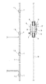
本実施形態においては、図1、図2に示すように、トロリ線T上に配置された複数の電路の接続部T1,T2,・・・Tnの接続不良を検出するために、これらの接続部T1,T2,・・・Tnを被温度管理部材とする。接続部T1,T2,・・・Tnの側面には、示温ラベル1が貼付されている。この示温ラベル1は、接続部T1,T2,・・・Tnの温度に応じて不可逆的に変色する。なお、示温ラベル1に代えて、同様の性質を持つ示温変色部材である示温塗料を塗布することができる。電車線路には、トロリ線Tに並行して、例えばき電線W、吊架線Mが張られている。これらを含む架空電線は、電車線と総称される。き電線W、吊架線M上にも、リード線Lとの接続部Cあるいは図示しないそれ自身の直線接続部を有する。これらの接続部C上にも同様の示温ラベル1が貼付されている。図において、き電線W上には自走機2が移動可能に取り付けられている。自走機2は、機体3上の前後部にき電線W上を転動するローラ4を設け、このローラ4をモータ5で駆動するようになっている。
【0016】
機体3上には、色センサ6が搭載されている。色センサ6は、カラーカメラヘッド7と、これに接続されたコントローラ8とを備えている。カラーカメラヘッド7は、機体3の下部に固定されており、側方のトロリ線Tに向けられている。コントローラ8は、機体3に固定されており、変色した示温ラベル1の設定色を検出して所定の電気信号を送出する。コントローラ8には、電気信号を記憶する記憶装置9が内蔵されている。記憶装置9にはICメモリカードのような外部記憶装置を用いることもできる。色センサ6は、自走機2により移動しながらトロリ線Tを連続して撮影していくことにより、接続部T1,T2,・・・Tnを順次監視し、所定の異常温度にある接続部T1,T2,・・・Tnの示温ラベル1が示す設定色をコントローラ8が検出して所定の電気信号に変換して、これを色情報として記憶装置9に記憶する。
【0017】
図3を参照して本発明の温度管理方法は、ステップS1で、トロリ線Tの所定区間の起点から終点まで、トロリ線T上の接続部T1,T2,・・・Tnに夫々示温ラベル1を貼付することを含んでいる。ステップS2では、色センサ6のコントローラ8に、検知すべき温度に対応する色を設定する。ステップS3では、自走機2をトロリ線Tに沿って所定区間の起点から終点までき電線W上を移動させながら、色センサ6でトロリ線Tを撮影し、トロリ線T上の接続部T1,T2,・・・Tnの示温ラベル1を含む画像情報を取り込む。ステップS4では、色センサ6のコントローラ8が画像中の各示温ラベル1の色を予め設定された検知すべき色と比較し、ステップS5,S6で各示温ラベル毎に比較結果を電気信号として送出する。ステップ7では、色センサ6のコントローラ8から送出される電気信号を、各示温ラベル1に対応して記憶装置9に記憶する。
このような処理を経て記憶装置に記憶されたトロリ線Tの接続部の温度情報は、接続部T1,T2,・・・Tnの接続不良の検出に利用することができる。
【0018】
なお、自走機2の移動距離を付随的に計測することにより接続不良個所の特定を確実にすることができるし、自走機2をき電線W、吊架線M等の他の電車線上で走行させることができ、この場合に、支持物等と干渉しないように適宜自走機2の構造を変更することができる。
また、本実施形態では、トロリ線T上の接続不良を検出するために温度管理を行うようにしたが、本発明はこれに限定されるものではなく、例えばカラーカメラヘッド7の向きを変更するなどしてき電線W、吊架線M等の他の電車線の接続部C上の示温ラベル1を撮影して同様の温度管理を行うことができるし、被温度管理部材が例えば変電所内の遮断器のような固定された設備である場合、被温度管理部材に貼付された示温ラベル1を常時定位置で固定的に撮影するように色センサ6を設置してもよい。
さらに、示温ラベル1の設定色を検出したら、直ちに警報を発する等の対応動作を行うようにできる。
本発明の他の実施形態として、一般の送電線上の複数の電路の接続部の接続不良を検出するために、これらの接続部を被温度管理部材とすることができる。この場合、並行する他の送電線上に自走機を取り付けることもできる。
【0019】
【発明の効果】
以上のように、本発明においては、被温度管理部材の温度を示温ラベル1のような示温変色部材の変色により、地上から手数、労力を伴わずに安全にしかも点検時間の制限を受けることなく検出することができ、特に電車線路のトロリ線やき電線の如き電路の接続部の接続不良を検出するのに最適であるという効果を有する。
【図面の簡単な説明】
【図1】本発明に係る温度管理装置の概略的平面図である。
【図2】温度管理装置の概略的側面図である。
【図3】温度管理方法のフローチャートである。
【符号の説明】
1 示温ラベル
2 自走機
6 色センサ
7 カラーカメラヘッド
8 コントローラ
9 記憶装置
T トロリ線
T1,T2,・・・Tn 接続部
W き電線[0001]
BACKGROUND OF THE INVENTION
TECHNICAL FIELD The present invention relates to an apparatus for managing the temperature of equipment, and in particular, connection at connection parts of electric circuits such as trolley wires and feeders arranged along a train line, and connection parts of electric circuits in general commercial power transmission equipment. The present invention relates to a temperature management device that is effective in applying defects to temperature inspection and a temperature management method using the same.
[0002]
[Prior art]
2. Description of the Related Art Conventionally, for example, a connection failure in a connection portion of an electric circuit such as a feeder line arranged along a train line is inspected by managing the temperature accompanying resistance heat generation. In this case, it has been proposed to use an infrared thermometer, a discoloration of the temperature indicating label, and a deformation of the shape memory alloy as the temperature measuring means.
[0003]
[Problems to be solved by the invention]
Since current flows only at the time of passing a train through a connection part of an electric circuit such as a trolley wire or feeder of a train track, the temperature drops after passing the train even if the temperature of the connection rises due to resistance heat generation. . Therefore, it is difficult to continuously measure the temperature at the connection portions of the plurality of electric circuits arranged along the train track using the infrared thermometer as the train passes. When attaching a temperature-indicating label with irreversible discoloration that changes color at a given temperature and visually checking the discoloration, the connection is often located at a high location. It is difficult to discriminate, and if it is a high place inspection work using a ladder, it will involve a lot of work, labor and danger. Even when using the method of visually inspecting the deformation of the shape memory alloy, there are the same problems as the temperature indication label, and the original shape is restored due to a change in temperature. There is a problem of being restricted.
Accordingly, the present invention is intended to provide a temperature management device capable of accurately detecting a discoloration of a temperature discoloration member such as a temperature label accurately and safely without using human hands, and a temperature management method using the same. is there.
[0004]
[Means for Solving the Problems]
In the present invention, in a train track that includes a trolley wire T and a feeder wire W installed along the trolley wire T, a plurality of electric circuits connected in a predetermined order along the trolley wire T are connected. The temperature change
[0005]
The present invention also includes a step of affixing a
[0014]
DETAILED DESCRIPTION OF THE INVENTION
An embodiment of the present invention will be described with reference to the drawings. FIG. 1 is a schematic plan view of a temperature management device according to the present invention, FIG. 2 is a schematic side view of the temperature management device according to the present invention, and FIG. 3 is a flowchart of the temperature management method according to the present invention.
[0015]
In this embodiment, as shown in FIGS. 1 and 2, in order to detect a connection failure of the connection portions T1, T2,... Tn of the plurality of electric circuits arranged on the trolley line T, these connections are detected. The parts T1, T2,... Tn are temperature management members. A
[0016]
A
[0017]
Referring to FIG. 3, in the temperature management method of the present invention, in step S1, the
The temperature information of the connection portion of the trolley wire T stored in the storage device through such processing can be used for detecting a connection failure of the connection portions T1, T2,.
[0018]
In addition, by measuring the moving distance of the self-propelled
In this embodiment, temperature management is performed to detect a connection failure on the trolley line T. However, the present invention is not limited to this, and the orientation of the
Furthermore, when the set color of the
As other embodiment of this invention, in order to detect the connection failure of the connection part of the some electric circuit on a general power transmission line, these connection parts can be used as a temperature management member. In this case, a self-propelled aircraft can be mounted on another parallel transmission line.
[0019]
【The invention's effect】
As described above, in the present invention, the temperature of the temperature-controlled member is discolored from the temperature discoloring member such as the
[Brief description of the drawings]
FIG. 1 is a schematic plan view of a temperature management device according to the present invention.
FIG. 2 is a schematic side view of a temperature management device.
FIG. 3 is a flowchart of a temperature management method.
[Explanation of symbols]
DESCRIPTION OF
Claims (4)
前記トロリ線に沿って所定の順番に並んで固定された複数の電路の接続部に付着された示温変色部材と、この示温変色部材を監視し、抵抗発熱により電路接続部の温度が所定値に達したときに示温変色部材が示す設定色を検出して所定の電気信号を送出する色センサとを具備し、この色センサは、前記示温変色部材を撮影するカラーカメラヘッドと、このカメラヘッドがとらえた示温変色部材の設定色を検出して所定の電気信号を送出するコントローラとを具備し、
前記カラーカメラヘッドは、前記き電線上を移動する自走機上に設置され、各電路の接続部に付着された示温変色部材を順次撮影するようになされ、前記コントローラから送出される電気信号が、各電路の接続部に対応して記憶装置に記憶されるようになされていることを特徴とする電車線路における電路接続部の温度管理装置。In a train track comprising a trolley wire and a feeder line installed along the trolley wire,
A temperature discoloration member attached to a connection portion of a plurality of electric circuits fixed in a predetermined order along the trolley wire, and the temperature discoloration member are monitored, and the temperature of the electric circuit connection portion reaches a predetermined value by resistance heating. A color sensor that detects a set color indicated by the temperature change color member and transmits a predetermined electrical signal when the temperature change color is reached, and the color sensor includes a color camera head for photographing the temperature change color member, and the camera head A controller for detecting a set color of the temperature-indicating color changing member and transmitting a predetermined electric signal;
The color camera head is installed on a self-propelled machine that moves on the feeder, is configured to sequentially photograph the temperature change color changing member attached to the connection portion of each electric circuit, and an electrical signal sent from the controller A temperature management device for an electric circuit connection portion in a train line, which is stored in a storage device corresponding to the connection portion of each electric circuit.
Priority Applications (1)
| Application Number | Priority Date | Filing Date | Title |
|---|---|---|---|
| JP29115296A JP3954672B2 (en) | 1996-10-14 | 1996-10-14 | Temperature management device and temperature management method using the same |
Applications Claiming Priority (1)
| Application Number | Priority Date | Filing Date | Title |
|---|---|---|---|
| JP29115296A JP3954672B2 (en) | 1996-10-14 | 1996-10-14 | Temperature management device and temperature management method using the same |
Publications (2)
| Publication Number | Publication Date |
|---|---|
| JPH10115560A JPH10115560A (en) | 1998-05-06 |
| JP3954672B2 true JP3954672B2 (en) | 2007-08-08 |
Family
ID=17765126
Family Applications (1)
| Application Number | Title | Priority Date | Filing Date |
|---|---|---|---|
| JP29115296A Expired - Fee Related JP3954672B2 (en) | 1996-10-14 | 1996-10-14 | Temperature management device and temperature management method using the same |
Country Status (1)
| Country | Link |
|---|---|
| JP (1) | JP3954672B2 (en) |
Families Citing this family (9)
| Publication number | Priority date | Publication date | Assignee | Title |
|---|---|---|---|---|
| JP2002215043A (en) * | 2001-01-15 | 2002-07-31 | Nippon Yusoki Co Ltd | Merchandise label and temperature management method |
| JP2009139101A (en) * | 2007-12-03 | 2009-06-25 | Nichiyu Giken Kogyo Co Ltd | Temperature control indicator and temperature control method using it |
| JP2009236582A (en) * | 2008-03-26 | 2009-10-15 | West Japan Railway Co | Temperature display means for railway electric facility |
| JP6330176B2 (en) * | 2014-06-12 | 2018-05-30 | 株式会社明電舎 | Line temperature monitoring device by image processing |
| JP6716930B2 (en) * | 2016-02-02 | 2020-07-01 | 株式会社明電舎 | Wire temperature monitoring device and method |
| JP7015173B2 (en) * | 2018-01-09 | 2022-02-15 | 日本信号株式会社 | Sensor system |
| JP6531310B1 (en) | 2018-04-17 | 2019-06-19 | 株式会社エコファースト | Monitoring system |
| KR102099782B1 (en) * | 2019-10-16 | 2020-04-10 | 주식회사 삼우씨엠건축사사무소 | Electrical wiring fixture in apartment buildings |
| CN112284563A (en) * | 2020-10-16 | 2021-01-29 | 江苏骠马智能工业设计研究有限公司 | Method for detecting temperature of power distribution cabinet by power inspection robot |
-
1996
- 1996-10-14 JP JP29115296A patent/JP3954672B2/en not_active Expired - Fee Related
Also Published As
| Publication number | Publication date |
|---|---|
| JPH10115560A (en) | 1998-05-06 |
Similar Documents
| Publication | Publication Date | Title |
|---|---|---|
| JP3954672B2 (en) | Temperature management device and temperature management method using the same | |
| CN101762327B (en) | Infrared temperature monitoring method and system of electrified railway contact network | |
| CN103471722B (en) | Intelligent mobile on-line temperature measuring system | |
| EP2546120B1 (en) | Method and stationery system for monitoring equipment of a railway vehicle | |
| CN205333126U (en) | Transformer substation valve room hangs rail and patrols and examines robot | |
| CN104034430B (en) | The temperature checking method and detecting system of automatic cruising imaging | |
| US20220057271A1 (en) | Apparatus for monitoring a switchgear | |
| CN108593706B (en) | Nondestructive testing system for material of winding of distribution transformer with two-end heating | |
| CN212624180U (en) | Intelligent inspection device | |
| CN111174917B (en) | Online temperature measurement camera shooting alarm system of electricity distribution room | |
| CN105680368B (en) | A kind of method for carrying out fault detect using unlimited continuation of the journey high-voltage maintenance aircraft | |
| CN104913851A (en) | On-line infrared temperature-measurement expert diagnosis system for electric equipment | |
| CN207528907U (en) | A kind of measurement instrument automatic monitoring device | |
| CN114279572B (en) | Automatic inspection system of electric cabinet based on infrared temperature measurement imaging | |
| CN110967117B (en) | Thermal imaging early warning system for power transmission line | |
| CN209559351U (en) | Off-line temperature detector applied to electronic welding element | |
| CN211061076U (en) | Online temperature measuring device for strain clamp of power transmission line | |
| CN201653380U (en) | Visual identification and heat distribution intelligence detecting system of motor car | |
| CN213336504U (en) | High voltage distribution cabinet wiring node temperature detection device | |
| JP2017138134A (en) | Wire temperature monitoring device and method | |
| CN108680598B (en) | Nondestructive testing method for material of distribution transformer winding with two ends heated | |
| CN112710238A (en) | Continuous casting billet length photographing and sizing device and method | |
| CN101823496B (en) | Motor car detecting method | |
| KR20150021619A (en) | Automatic Test Equipment for Insulators using Thermography | |
| JP2006131173A (en) | Electric train line monitoring system |
Legal Events
| Date | Code | Title | Description |
|---|---|---|---|
| A977 | Report on retrieval |
Free format text: JAPANESE INTERMEDIATE CODE: A971007 Effective date: 20050222 |
|
| A131 | Notification of reasons for refusal |
Free format text: JAPANESE INTERMEDIATE CODE: A131 Effective date: 20050323 |
|
| A521 | Written amendment |
Free format text: JAPANESE INTERMEDIATE CODE: A523 Effective date: 20050428 |
|
| A131 | Notification of reasons for refusal |
Free format text: JAPANESE INTERMEDIATE CODE: A131 Effective date: 20051004 |
|
| A521 | Written amendment |
Free format text: JAPANESE INTERMEDIATE CODE: A523 Effective date: 20051026 |
|
| TRDD | Decision of grant or rejection written | ||
| A01 | Written decision to grant a patent or to grant a registration (utility model) |
Free format text: JAPANESE INTERMEDIATE CODE: A01 Effective date: 20070404 |
|
| A61 | First payment of annual fees (during grant procedure) |
Free format text: JAPANESE INTERMEDIATE CODE: A61 Effective date: 20070427 |
|
| R150 | Certificate of patent or registration of utility model |
Free format text: JAPANESE INTERMEDIATE CODE: R150 |
|
| FPAY | Renewal fee payment (event date is renewal date of database) |
Free format text: PAYMENT UNTIL: 20100511 Year of fee payment: 3 |
|
| FPAY | Renewal fee payment (event date is renewal date of database) |
Free format text: PAYMENT UNTIL: 20110511 Year of fee payment: 4 |
|
| FPAY | Renewal fee payment (event date is renewal date of database) |
Free format text: PAYMENT UNTIL: 20120511 Year of fee payment: 5 |
|
| FPAY | Renewal fee payment (event date is renewal date of database) |
Free format text: PAYMENT UNTIL: 20120511 Year of fee payment: 5 |
|
| S533 | Written request for registration of change of name |
Free format text: JAPANESE INTERMEDIATE CODE: R313533 |
|
| FPAY | Renewal fee payment (event date is renewal date of database) |
Free format text: PAYMENT UNTIL: 20120511 Year of fee payment: 5 |
|
| R350 | Written notification of registration of transfer |
Free format text: JAPANESE INTERMEDIATE CODE: R350 |
|
| LAPS | Cancellation because of no payment of annual fees |