JP3951004B2 - Hydrostatic type axial piston machine - Google Patents
Hydrostatic type axial piston machine Download PDFInfo
- Publication number
- JP3951004B2 JP3951004B2 JP04891197A JP4891197A JP3951004B2 JP 3951004 B2 JP3951004 B2 JP 3951004B2 JP 04891197 A JP04891197 A JP 04891197A JP 4891197 A JP4891197 A JP 4891197A JP 3951004 B2 JP3951004 B2 JP 3951004B2
- Authority
- JP
- Japan
- Prior art keywords
- spool valve
- rotary spool
- axial piston
- piston machine
- swash plate
- Prior art date
- Legal status (The legal status is an assumption and is not a legal conclusion. Google has not performed a legal analysis and makes no representation as to the accuracy of the status listed.)
- Expired - Fee Related
Links
Images


Classifications
-
- F—MECHANICAL ENGINEERING; LIGHTING; HEATING; WEAPONS; BLASTING
- F04—POSITIVE - DISPLACEMENT MACHINES FOR LIQUIDS; PUMPS FOR LIQUIDS OR ELASTIC FLUIDS
- F04B—POSITIVE-DISPLACEMENT MACHINES FOR LIQUIDS; PUMPS
- F04B1/00—Multi-cylinder machines or pumps characterised by number or arrangement of cylinders
- F04B1/12—Multi-cylinder machines or pumps characterised by number or arrangement of cylinders having cylinder axes coaxial with, or parallel or inclined to, main shaft axis
- F04B1/26—Control
- F04B1/28—Control of machines or pumps with stationary cylinders
- F04B1/29—Control of machines or pumps with stationary cylinders by varying the relative positions of a swash plate and a cylinder block
- F04B1/295—Control of machines or pumps with stationary cylinders by varying the relative positions of a swash plate and a cylinder block by changing the inclination of the swash plate
Description
【0001】
【発明の属する技術分野】
本発明は、斜板構造のハイドロスタティック式のアキシャルピストン機械であって、斜板が設けられており、該斜板の傾斜位置が、作動圧によって負荷可能な少なくとも1つの調節ピストンによって調節可能であり、調節ピストンに通じる管路に、電気的に操作可能な作動弁が配置されている形式のものに関する。
【0002】
【従来の技術】
このような形式のアキシャルピストン機械は主に、ハイドロリック循環路においてハイドロポンプとして用いられる。このアキシャルピストン機械の作動中には、斜板の傾斜位置の変化によって行程量を種々異なる作動状態に適合可能であると有利であることが判明している。このためには、機械式、ハイドロリック式、又は電気的に制御可能且つ作動可能な、機械式又はハイドロリック式の位置調節装置が必要である。
【0003】
ハイドロリック式の位置調節装置は、作動圧によって負荷可能な少なくとも1つの調節ピストンを有しており、この調節ピストンは、斜板に係合していて、斜板の傾斜位置ひいては行程量を規定可能である。作動圧を生ぜしめるためには、調節ピストンに向けて案内された管路内に作動弁が配置されている。
【0004】
請求項1の上位概念によるアキシャルピストン機械の場合には、行程量調節の制御及びコントロールを改善するために、アキシャルピストン機械が電気的に作動可能に構成すると有利であることが判明している。このためには、電気的に作動可能な弁、通常は、比例磁石によって制御される比例弁が設けられたシステムが既知である。
【0005】
この調節の場合、比例磁石は電気的な制御信号を磁力に変換し、この磁力が、ばね力に抗して減圧弁を変位させる。減圧弁は圧力源に接続されていて、変位に関連して制御圧を生ぜしめる。制御圧は、ばね力で負荷可能な制御ピストンを変位させ、この制御ピストンの移動距離は、機械的な中間部材を介して、斜板に配置された作動弁に伝達される。従って制御ピストンは作動弁を機械式に作動させる。制御弁は供給圧から作動圧を生ぜしめ、この作動圧によって、ハイドロリック式の位置調節装置の調節ピストンが負荷される。従って斜板が位置調節される。位置調節距離は、機械装置を介して作動弁に戻され、この場合、制御ピストンの距離に関連して、斜板の所望の傾斜位置が達成された際に制御弁が再び閉鎖される。
【0006】
従って、電気的な制御信号によって斜板に旋回角度を生ぜしめるためには、このシステムの場合、信号鎖において5つの変換が必要である。これらの変換のうちのそれぞれの変換が誤差の偏差を伴っていて、構成部分を必要とする。ばね力によって負荷される構成部分には、更に摩擦が生じ、摩擦は、このシステムにおいてヒステリシスの形で作用する。作動弁を直接に斜板に配置することによって、供給圧管路及び調節ピストンに通じる管路のために高い構造上の手間がかかる。
【0007】
【発明が解決しようとする課題】
本発明の課題は、冒頭で述べた形式のハイドロスタティック式のアキシャルピストン機械を改良して、斜板の電気的・ハイドロリック式の調節が簡単な構造によって得られるような、ハイドロスタティック式のアキシャルピストン機械を提供することにある。
【0008】
【課題を解決するための手段】
この課題を解決するために本発明の構成では、作動弁が、作動圧によって負荷される調節ピストンを負荷可能な回転スプール弁として形成されていて、ステップモータによって作動可能であり、回転スプール弁が回転可能な制御軸を有しており、供給圧及びタンク圧によって負荷可能な少なくとも各1つの溝が設けられており、回転スプール弁が、制御軸の外周面を取り囲む回転可能なスリーブを有しており、溝が、タンク圧又は作動圧によって調節ピストンを負荷するために設けられており、回転スプール弁の回転可能な両構成部分のうちの一方が、ステップモータの出力軸に相対回動不能に結合されており、回転スプール弁の回転可能な別の構成部分が斜板と作用接続しているようにした。
【0009】
【発明の効果】
本発明によれば、最小限のハイドロリック式及び機械式の中間部材を用いて、電気的な制御信号が斜板の傾斜位置に変換される。
【0010】
電気的な制御信号は、作動圧を調節ピストン対して調節する作動弁を直接に作動させる。作動弁の変位は、この場合、調節ピストンにおいて斜板の所望の傾斜位置が得られるような作動圧を生ぜしめる。信号鎖は作動弁の直接の作動時に、電気的な制御信号から所望の斜板位置までに3つの変換しか必要としない。
【0011】
本発明の有利な構成は、制御弁がステップモータによって作動可能に構成されていることにある。ステップモータの制御のための電気的な信号は、この場合計数パルスから成っており、この計数パルスは、摩擦の影響とは無関係にステップモータの出力軸の角度位置内で形成される。
【0012】
この場合、作動弁が、調節ピストンを作動圧によって負荷する回転スプール弁として形成されていると有利である。ステップモータによって作動される回転スプール弁は、回転スプール弁の制御縁部において作動圧を形成するための簡単な可能性を提供する。
【0013】
更に、回転スプール弁が回転可能な制御軸を有していると有利である。この場合、供給圧及びタンク圧によって負荷可能な少なくとも各1つの溝が設けられており、回転スプール弁が、制御軸の外周面を取り囲む回転可能なスリーブを有しており、溝と調節ピストンをタンク圧又は作動圧によって負荷するための溝が設けられていると有利である。制御軸の、スリーブに対する回転角度の変化によって、回転スプール弁における制御縁部が形成されるので、調節ピストンに向けて作動圧が形成されるか、又は調節ピストンはタンク圧によって負荷される。
【0014】
調節ピストンはこの場合、復動式シリンダとして形成してもよく、又は、例えば斜板の旋回軸線の両側に配置された単動式の複数のシリンダが設けられていてもよい。前者の場合には、スリーブの溝が、シリンダのピストン室及びシリンダ室に接続されている。後者の場合には、各1つの溝が、シリンダのピストン室に接続している。回転スプール弁のこの構成では、更に、制御軸の機能とスリーブの機能とを交換してもよい。この場合、スリーブの溝に供給圧及びタンク圧を接続して、調節ピストンを負荷するための制御軸の溝が設けられる。
【0015】
この場合、回転スプール弁の回転可能な両構成部分のうちの一方がステップモータの出力軸に相対回動不能に結合されていると有利である。これにより電気的な入力信号は直接に回転スプール弁の回転角度に変換され、調節ピストンのための作動圧を生ぜしめる。
【0016】
回転スプール弁の回転可能な別の構成部分が斜板に係合していると有利である。この配置によって、ステップモータ軸の変位が斜板の傾斜位置と簡単に比較可能となる。従って、回転スプール弁内の両構成部分の回転角度に関して差異がある場合は、調節ピストンだけが作動圧によって負荷可能である。
【0017】
本発明の別の構成では、ステップモータの出力軸又は、回転スプール弁の、出力軸に相対回動不能に結合された構成部分は、出力軸をゼロ位置にもたらす装置と作用接続している。このことによって、ステップモータの出力軸及びこれに対応する回転スプール弁の構成部分は、例えば停電時にゼロ位置に戻され、従って斜板がゼロ位置へと旋回する。
【0018】
特に、ステップモータの出力軸又は、回転スプール弁の、出力軸に相対回動不能に結合された構成部分が、出力軸の回転角度及び/又はゼロ位置を監視する装置と作用接続していると有利である。このことによって、ステップモータが電気的な計数パルスを回転スプール弁における回転運動に変換しない場合に、出力軸の回転角度及び/又はゼロ位置を監視することが可能になる。従って、セイフティー・ルーティン(Sicherheitsroutinen)においてゼロ位置を常に修正することができる。
【0019】
本発明の有利な別の構成では、回転スプールの、斜板と作用接続する回転可能な構成部分と斜板との間に機械的な伝動装置が配置されている。この配置によって、ステップモータの出力軸の回転角度と斜板の傾斜位置との間の伝達比を変化させることができる。例えば、斜板の傾斜位置と回転スプール弁の回転角度との間の伝達比が機械的な伝動装置で選択される場合には、斜板における所望の変位が、回転スプール弁の、対応して大きくなる回転角度に反映される。このことによって、高い精度で斜板の迅速な調節を行うことができる。更に、回転スプール弁及びステップモータの寸法が、場合によっては減じられる。
【0020】
本発明の有利な実施例では、ステップモータの出力軸は回転スプール弁の回転可能な制御軸に相対回動不能に結合されており、回転スプール弁のスリーブは斜板に係合している。この構成によって、アキシャルピストン機械の調節装置の構造が簡単になる。
【0021】
更に、この場合、回転スプール弁とステップモータとが軸方向機械のケーシングに斜板から分離されて配置されていてもよく、このことによって、制御圧力管路のための構造上の手間と、調節ピストンに通じる管路の構造上の手間とが著しく減じられる。この場合、回転スプール弁はステップモータと共に、回転スプール弁の長手方向軸線をアキシャルピストン機械の回転軸線に対して直角にして、場合によっては斜板の旋回軸線に整合させるか又はこの旋回軸線に対して平行になるようにケーシングに配置することができる。
【0022】
本発明の有利な別の構成は、ステップモータが回転スプール弁と共に、アキシャルピストン機械の回転軸線に対して平行に配置されていることにある。この配置は、特に有利であることが判明した。なぜならば、このことによって、構造スペース、特にアキシャルピストン機械の構造高さが減じられるからである。
【0023】
【発明の実施の形態】
以下に、本発明の実施の形態を図面につき詳しく説明する。
【0024】
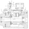
図1は、本発明による電気的に作動可能な作動弁2を備えたアキシャルピストン機械1を示している。回転スプール弁3として形成された作動弁は、本発明によればステップモータ4によって作動可能である。斜板5は、斜板の旋回軸線の両側に配置された複数の調節ピストン6によって傾斜位置で調節可能である。
【0025】
回転スプ−ル弁3は回転可能な制御軸7と、制御軸7の外周面を取り囲む回転可能なスリーブ8とを有している。制御軸7には溝9が設けられており、溝9は、スリーブ8に配置された環状の溝10と供給圧管路11とを介して、図示されていない補助ポンプによって提供される供給圧によって負荷可能である。溝9に対して軸方向でずらされた溝12は、スリーブ8に配置された環状の溝13と管路14とによって、アキシャルピストン機械のケーシングに接続されている。
【0026】
スリーブ8には更に環状の2つの溝15,16が位置しており、これらの溝15,16は、制御軸7に配置された溝9,12に接続することができ、各1つの管路17,18によって調節ピストン6に接続されている。
【0027】
ステップモータ4の出力軸19は、図示の実施例では回転スプール弁3の制御軸7に相対回動不能に結合されている。
【0028】
斜板5には構成部分20が配置されており、この構成部分20はスリーブ8に相対回動不能に結合されている。回転スプール弁3とステップモータ2とは、アキシャルピストン機械のケーシングに配置されている。
【0029】
図1に示した実施例の場合には、回転スプール弁3は、ステップモータ4と回転スプール弁3との長手方向軸線21がアキシャルピストン機械1の回転軸線22に対して直角に延びて、斜板5の旋回軸線に整合するように配置されている。ステップモータ4によって回転スプール弁3において調節される回転角度は、この構成の場合、斜板5の旋回軸線に対する旋回角度に対応している。
【0030】
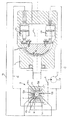
図2に示した本発明の構成は、ステップモータ4と回転スプール弁3との長手方向軸線21がアキシャルピストン機械1の回転軸線22に対して平行である配置を示している。判りやすくするために、図1の場合と同じ構成部分には同じ符号を付してある。斜板5には伝動装置構成部分23が固定されており、伝動装置構成部分23は、回転スプール弁3のスリーブ8と結合されている。
【0031】
図3によると、伝動構成部分23は回転スプール弁3の範囲で球状に形成されていて、回転スプール弁3のスリーブ8に、溝状の切欠き24を介して結合されている。この構成の場合には更に、斜板の傾斜位置と回転スプール弁の回転角度との間で1:2の範囲の伝動装置が設けられている。このことによって、伝動装置に基づき回転スプール弁における40°の回転角度は、斜板における20°の変位に相当する。
【0032】
図4には、作動弁の可能な1つの切換え図が示されている。
【0033】
回転スプール弁3の制御軸7は、互いに180°だけずらされた2つの溝9a,9bを有しており、これらの溝9a,9bは、管路11を介して、補助ポンプ22によって生ぜしめられた供給圧によって負荷されている。これらの溝9a,9bに対して90°だけずらされて同様に2つの溝12a,12bが配置されており、これらの溝12a,12bは、管路14を介してタンク23又はアキシャルピストン機械1のケーシングに接続されている。
【0034】
回転スプール弁3のスリーブ8は、互いに180°だけずらされた各2つの溝15a,15b及び16a,16bを有しており、これらの溝15a,15b,16a,16bは、管路17,18を介して、斜板5の旋回軸線の両側に配置された調節ピストン6a,6bに接続されている。
【0035】
斜板位置の調節のためには、計数パルスから形成された電気的な入力信号が、ステップモータ4内で、計数パルスの数に対応した、出力軸19と、回転スプール弁3の、出力軸19に相対回動不能に結合された制御軸7との回転角度に変換される。この場合、制御軸7が例えば時計回り方向で図2のように変位すると、作動圧は補助ポンプ22から、管路11、溝9a,9b、溝15a,15b、ひいては管路17を介して調節ピストン6bのピストン室に流入する。同時に、調節ピストン6aの、管路18、溝16a,16b、溝12a,12b、管路14を介してのタンク23への接続が行われる。斜板5はこのことによって符号24の方向に変位する。回転スプール弁3のスリーブ8の、図1若しくは図2に示した構成部分20,23を介しての斜板5との機械的な連結によって、同時にスリーブ8が斜板位置に関連して回転され、且つ、所望の斜板位置に到達すると、回転スプール弁において制御縁部を閉鎖する。
【図面の簡単な説明】
【図1】本発明によるアキシャルピストン機械の断面図である
【図2】本発明の別の実施例を示す図である。
【図3】図2の1−1に沿った断面図である。
【図4】作動弁の切換状態を示す図である。
【符号の説明】
1 アキシャルピストン機械、 2 作動弁、 3 回転スプール弁、 4 ステップモータ、 5 斜板、 6 調節ピストン、 7 制御軸、 8 スリーブ、 9,9a,9b 溝、 10 溝、 11 供給圧管路、 12,12a,12b 溝、 13 溝、 14 管路、 15,15a,15b 溝、 16,16a,16b 溝、 17,18 管路、 19 出力軸、 20 構成部分、 21 長手方向軸線、 22 回転軸線、補助ポンプ、 23 タンク、 24 方向[0001]
BACKGROUND OF THE INVENTION
The present invention is a hydrostatic type axial piston machine having a swash plate structure, in which a swash plate is provided, and an inclination position of the swash plate can be adjusted by at least one adjustment piston that can be loaded by operating pressure. There, the conduit leading to the adjusting piston, to those of the type electrically operable work valve operating is located.
[0002]
[Prior art]
This type of axial piston machine is mainly used as a hydropump in the hydraulic circuit. During the operation of this axial piston machine, it has proven to be advantageous to be able to adapt the stroke amount to different operating states by changing the tilt position of the swash plate. This requires a mechanical, hydraulic, or mechanical or hydraulic position adjustment device that can be controlled and actuated electrically.
[0003]
The hydraulic position adjusting device has at least one adjusting piston that can be loaded by operating pressure, and this adjusting piston is engaged with the swash plate and defines the inclination position of the swash plate and thus the stroke amount. Is possible. In order to generate an operating pressure, an operating valve is arranged in a conduit guided towards the adjusting piston.
[0004]
In the case of an axial piston machine according to the superordinate concept of claim 1, it has proven to be advantageous if the axial piston machine is configured to be electrically operable in order to improve the control and control of the stroke adjustment. For this purpose, systems are known in which an electrically actuable valve, usually a proportional valve controlled by a proportional magnet, is provided.
[0005]
In this adjustment, the proportional magnet converts an electric control signal into a magnetic force, and this magnetic force displaces the pressure reducing valve against the spring force. The pressure reducing valve is connected to a pressure source and generates a control pressure in relation to the displacement. The control pressure displaces a control piston that can be loaded with a spring force, and the movement distance of the control piston is transmitted to an operating valve disposed on the swash plate via a mechanical intermediate member. The control piston thus mechanically actuates the actuating valve. The control valve generates an operating pressure from the supply pressure, and this operating pressure loads the adjusting piston of the hydraulic position adjusting device. Accordingly, the position of the swash plate is adjusted. The position adjustment distance is returned to the actuating valve via the mechanical device, where the control valve is closed again when the desired tilted position of the swash plate is achieved in relation to the distance of the control piston.
[0006]
Therefore, in order to produce a swivel angle in the swashplate by means of electrical control signals, this system requires five transformations in the signal chain. Each of these transformations is accompanied by an error deviation and requires a component. Further friction occurs in the components loaded by the spring force, which acts in the form of hysteresis in this system. By placing the actuating valve directly on the swash plate, high construction costs are required for the supply pressure line and the line leading to the adjustment piston.
[0007]
[Problems to be solved by the invention]
The object of the present invention is to improve a hydrostatic axial piston machine of the type mentioned at the outset so that the electrical and hydraulic adjustment of the swashplate can be obtained with a simple structure. To provide a piston machine.
[0008]
[Means for Solving the Problems]
In order to solve this problem, in the configuration of the present invention, the operating valve is formed as a rotary spool valve capable of loading an adjustment piston loaded by the operating pressure, and can be operated by a step motor. A rotatable control shaft has at least one groove that can be loaded by supply pressure and tank pressure, and the rotary spool valve has a rotatable sleeve that surrounds the outer peripheral surface of the control shaft. The groove is provided to load the adjustment piston by tank pressure or operating pressure, and one of the rotatable components of the rotary spool valve cannot rotate relative to the output shaft of the step motor. And another rotatable component of the rotary spool valve is in operative connection with the swash plate .
[0009]
【The invention's effect】
According to the present invention, an electrical control signal is converted into a tilted position of the swash plate using a minimum of hydraulic and mechanical intermediate members.
[0010]
The electrical control signal directly activates an actuation valve that regulates the actuation pressure relative to the regulating piston. The displacement of the actuating valve in this case gives rise to an actuating pressure such that the desired tilting position of the swash plate is obtained at the adjusting piston. The signal chain requires only three conversions from the electrical control signal to the desired swashplate position when the actuating valve is directly actuated.
[0011]
An advantageous configuration of the invention is that the control valve is configured to be operable by a step motor. The electrical signal for the control of the step motor consists in this case of a counting pulse, which is formed within the angular position of the output shaft of the step motor irrespective of the effect of friction.
[0012]
In this case, it is advantageous if the actuating valve is formed as a rotary spool valve that loads the adjusting piston with the actuating pressure. A rotary spool valve actuated by a step motor offers a simple possibility for creating an actuation pressure at the control edge of the rotary spool valve.
[0013]
Furthermore, it is advantageous if the rotary spool valve has a rotatable control shaft. In this case, at least one groove that can be loaded by the supply pressure and the tank pressure is provided, and the rotary spool valve has a rotatable sleeve that surrounds the outer peripheral surface of the control shaft. It is advantageous if a groove for loading by tank pressure or operating pressure is provided. A change in the rotation angle of the control shaft relative to the sleeve forms a control edge in the rotary spool valve, so that an operating pressure is created towards the adjusting piston or the adjusting piston is loaded by the tank pressure.
[0014]
In this case, the adjustment piston may be formed as a return-acting cylinder, or may be provided with a plurality of single-acting cylinders arranged on both sides of the pivot axis of the swash plate, for example. In the former case, the groove of the sleeve is connected to the piston chamber and the cylinder chamber of the cylinder. In the latter case, each one groove is connected to the piston chamber of the cylinder. In this configuration of the rotary spool valve, the function of the control shaft and the function of the sleeve may be exchanged. In this case, a supply shaft and a tank pressure are connected to the groove of the sleeve to provide a control shaft groove for loading the adjustment piston.
[0015]
In this case, it is advantageous if one of the two rotatable components of the rotary spool valve is coupled to the output shaft of the step motor so as not to rotate relative to it. As a result, the electrical input signal is directly converted into the rotation angle of the rotary spool valve, which generates an operating pressure for the adjusting piston.
[0016]
It is advantageous if another rotatable component of the rotary spool valve engages the swash plate. With this arrangement, the displacement of the step motor shaft can be easily compared with the inclined position of the swash plate. Thus, if there is a difference with respect to the rotation angle of both components in the rotary spool valve, only the adjustment piston can be loaded by the operating pressure.
[0017]
In another configuration of the invention, the output shaft of the step motor or the component of the rotary spool valve that is non-rotatably coupled to the output shaft is operatively connected to a device that brings the output shaft to the zero position. As a result, the output shaft of the step motor and the corresponding components of the rotary spool valve are returned to the zero position, for example, in the event of a power failure, so that the swash plate pivots to the zero position.
[0018]
In particular, when the output shaft of the step motor or the component of the rotary spool valve that is coupled to the output shaft so as not to rotate relative to the output shaft is operatively connected to a device that monitors the rotation angle and / or zero position of the output shaft It is advantageous. This makes it possible to monitor the rotation angle and / or zero position of the output shaft when the stepping motor does not convert electrical counting pulses into rotational movement in the rotary spool valve. Therefore, the zero position can always be corrected in the safety routine.
[0019]
In a further advantageous configuration of the invention, a mechanical transmission is arranged between the swash plate and the rotatable component of the rotary spool that is operatively connected to the swash plate. With this arrangement, the transmission ratio between the rotation angle of the output shaft of the step motor and the inclined position of the swash plate can be changed. For example, if the transmission ratio between the inclined position of the swash plate and the rotation angle of the rotary spool valve is selected by a mechanical transmission, the desired displacement in the swash plate will be corresponding to that of the rotary spool valve. It is reflected in the increasing rotation angle. This makes it possible to adjust the swash plate quickly with high accuracy. Furthermore, the dimensions of the rotary spool valve and the step motor are sometimes reduced.
[0020]
In an advantageous embodiment of the invention, the output shaft of the step motor is non-rotatably coupled to the rotatable control shaft of the rotary spool valve, and the sleeve of the rotary spool valve engages the swash plate. This configuration simplifies the structure of the adjusting device for the axial piston machine.
[0021]
Furthermore, in this case, the rotary spool valve and the step motor may be arranged separately from the swash plate in the casing of the axial machine, which makes it possible to adjust the construction effort and control for the control pressure line. The structural effort of the conduit leading to the piston is significantly reduced. In this case, the rotary spool valve, together with the step motor, has the longitudinal axis of the rotary spool valve perpendicular to the axis of rotation of the axial piston machine, and in some cases is aligned with or relative to the pivot axis of the swash plate. Can be arranged in the casing so as to be parallel to each other.
[0022]
Another advantageous configuration of the invention consists in that the stepper motor, together with the rotary spool valve, is arranged parallel to the axis of rotation of the axial piston machine. This arrangement has been found to be particularly advantageous. This is because this reduces the structural space, in particular the structural height of the axial piston machine.
[0023]
DETAILED DESCRIPTION OF THE INVENTION
In the following, embodiments of the present invention will be described in detail with reference to the drawings.
[0024]
FIG. 1 shows an axial piston machine 1 with an electrically actuated
[0025]
The
[0026]
The
[0027]
In the illustrated embodiment, the output shaft 19 of the step motor 4 is coupled to the control shaft 7 of the
[0028]
A
[0029]
In the case of the embodiment shown in FIG. 1, the
[0030]
The configuration of the present invention shown in FIG. 2 shows an arrangement in which the
[0031]
According to FIG. 3, the
[0032]
FIG. 4 shows one possible switching diagram of the actuating valve.
[0033]
The control shaft 7 of the
[0034]
The
[0035]
In order to adjust the swash plate position, an electric input signal formed from the counting pulse is output from the output shaft 19 corresponding to the number of counting pulses in the step motor 4 and the output shaft of the
[Brief description of the drawings]
FIG. 1 is a cross-sectional view of an axial piston machine according to the present invention. FIG. 2 is a diagram showing another embodiment of the present invention.
FIG. 3 is a cross-sectional view taken along 1-1 in FIG. 2;
FIG. 4 is a diagram showing a switching state of an operating valve.
[Explanation of symbols]
DESCRIPTION OF SYMBOLS 1 Axial piston machine, 2 Actuation valve, 3 Rotary spool valve, 4 Step motor, 5 Swash plate, 6 Adjustment piston, 7 Control shaft, 8 Sleeve, 9, 9a, 9b Groove, 10 Groove, 11 Supply pressure line, 12, 12a, 12b groove, 13 groove, 14 pipe, 15, 15a, 15b groove, 16, 16a, 16b groove, 17, 18 pipe, 19 output shaft, 20 component, 21 longitudinal axis, 22 rotation axis, auxiliary Pump, 23 tanks, 24 directions
Claims (8)
Applications Claiming Priority (2)
| Application Number | Priority Date | Filing Date | Title |
|---|---|---|---|
| DE19608228A DE19608228B4 (en) | 1996-03-04 | 1996-03-04 | Hydrostatic axial piston machine |
| DE19608228.5 | 1996-03-04 |
Publications (2)
| Publication Number | Publication Date |
|---|---|
| JPH09242664A JPH09242664A (en) | 1997-09-16 |
| JP3951004B2 true JP3951004B2 (en) | 2007-08-01 |
Family
ID=7787123
Family Applications (1)
| Application Number | Title | Priority Date | Filing Date |
|---|---|---|---|
| JP04891197A Expired - Fee Related JP3951004B2 (en) | 1996-03-04 | 1997-03-04 | Hydrostatic type axial piston machine |
Country Status (3)
| Country | Link |
|---|---|
| US (2) | US6155798A (en) |
| JP (1) | JP3951004B2 (en) |
| DE (1) | DE19608228B4 (en) |
Families Citing this family (23)
| Publication number | Priority date | Publication date | Assignee | Title |
|---|---|---|---|---|
| US6460450B1 (en) | 1999-08-05 | 2002-10-08 | R. Sanderson Management, Inc. | Piston engine balancing |
| DE19842029B4 (en) | 1998-09-14 | 2005-02-17 | Sauer-Sundstrand Gmbh & Co. | Adjustment of hydrostatic axial piston machines by means of stepper motor |
| US6913447B2 (en) * | 2002-01-22 | 2005-07-05 | R. Sanderson Management, Inc. | Metering pump with varying piston cylinders, and with independently adjustable piston strokes |
| US6918357B2 (en) * | 2003-04-24 | 2005-07-19 | Ranco Incorporated Of Delaware | Stepper motor driven fluid valve and associated method of use |
| US6994310B2 (en) * | 2003-04-24 | 2006-02-07 | Ranco Incorporated Of Delaware | Stepper motor driven valve for thermal management and associated method of use |
| US7503173B2 (en) * | 2005-02-08 | 2009-03-17 | Parker-Hannifin Corporation | Control devices for swashplate type variable displacement piston pump |
| US8413572B1 (en) | 2006-11-22 | 2013-04-09 | Westendorf Manufacturing, Co. | Auto attachment coupler with abductor valve |
| US7644646B1 (en) | 2007-06-13 | 2010-01-12 | Sauer-Danfoss, Inc. | Three position servo system to control the displacement of a hydraulic motor |
| US7730826B2 (en) * | 2007-07-31 | 2010-06-08 | Sauer-Danfoss Inc. | Swashplate type axial piston device having apparatus for providing three operating displacements |
| DE102007048316B4 (en) | 2007-10-09 | 2010-05-27 | Danfoss A/S | Hydraulic axial piston machine |
| US8074558B2 (en) * | 2008-04-30 | 2011-12-13 | Caterpillar Inc. | Axial piston device having rotary displacement control |
| US8074451B2 (en) * | 2008-06-02 | 2011-12-13 | Caterpillar Inc. | Electric motor actuation of a hydrostatic pump |
| DE102009021833A1 (en) | 2009-05-19 | 2010-11-25 | Robert Bosch Gmbh | Hydraulic drive and rotary valve for a hydraulic drive |
| US8579599B2 (en) * | 2010-03-26 | 2013-11-12 | Schlumberger Technology Corporation | System, apparatus, and method for rapid pump displacement configuration |
| CN102213204A (en) * | 2011-05-23 | 2011-10-12 | 西安交通大学 | Variable device for diacytic-type axial plunger bidirectional variable pump |
| DE102012012141A1 (en) | 2012-06-20 | 2013-12-24 | Robert Bosch Gmbh | Hydrostatic axial piston machine for use as e.g. hydro pump in hybrid drive for driving vehicle, has feeding back device comprising torsion and/or spiral springs, which are directly or indirectly clamped between swash plate and adjuster |
| DE102012106906A1 (en) | 2012-07-30 | 2014-01-30 | Linde Hydraulics Gmbh & Co. Kg | Hydrostatic displacement machine has setting valve unit whose axial displacement is controlled with respect to return valve unit for applying piston-pressure chambers with actuator pressure |
| EP2888475B1 (en) * | 2012-07-30 | 2016-09-14 | Parker Hannifin Corporation | Pump control system and method |
| DE102012221922A1 (en) * | 2012-11-29 | 2014-06-05 | Hawe Inline Hydraulik Gmbh | Pump, in particular axial piston pump with scanning on the swash plate |
| DE102014113665A1 (en) | 2014-09-22 | 2016-03-24 | Linde Hydraulics Gmbh & Co. Kg | Adjusting device of a hydrostatic axial piston machine in swash plate design |
| US10247178B2 (en) | 2016-03-28 | 2019-04-02 | Robert Bosch Gmbh | Variable displacement axial piston pump with fluid controlled swash plate |
| DE102016015779A1 (en) | 2016-12-22 | 2018-06-28 | Danfoss Power Solutions Gmbh & Co. Ohg | Displacement control arrangement for an axial piston pump |
| DE102016226039B3 (en) | 2016-12-22 | 2018-02-08 | Danfoss Power Solutions Gmbh & Co. Ohg | DISPLACEMENT CONTROL ARRANGEMENT FOR AN AXIAL PISTON PUMP |
Family Cites Families (13)
| Publication number | Priority date | Publication date | Assignee | Title |
|---|---|---|---|---|
| DE2037635A1 (en) * | 1970-07-29 | 1972-02-03 | Robert Bosch Gmbh, 7000 Stuttgart | Adjustable axial piston machine |
| US3803843A (en) * | 1971-08-16 | 1974-04-16 | Sundstrand Corp | Hydromechanical transmission |
| US3905274A (en) * | 1974-01-28 | 1975-09-16 | Gen Motors Corp | Rotary timing valve |
| US3974715A (en) * | 1974-12-09 | 1976-08-17 | Caterpillar Tractor Co. | Null and gain adjustment mechanism for hydrostatic pumps and motors |
| US4355506A (en) * | 1977-08-26 | 1982-10-26 | Leonard Willie B | Pump-motor power limiter and pressure relief |
| US4426911A (en) * | 1980-02-01 | 1984-01-24 | The Boeing Company | Rotary digital electrohydraulic actuator |
| DE3213958A1 (en) * | 1981-08-21 | 1983-03-03 | Robert Bosch Gmbh, 7000 Stuttgart | ELECTROHYDRAULIC ADJUSTMENT FOR A HYDROSTATIC MACHINE |
| US4494911A (en) * | 1983-04-29 | 1985-01-22 | General Signal Corporation | Piston pump servo control |
| JPS61153057A (en) * | 1984-12-26 | 1986-07-11 | Honda Motor Co Ltd | Static hydraulic type continuously variable transmission |
| JPH0374581A (en) * | 1989-08-17 | 1991-03-29 | Toyota Autom Loom Works Ltd | Driving load control device for variable displacement hydraulic pump |
| JPH07324678A (en) * | 1994-05-31 | 1995-12-12 | Nippondenso Co Ltd | Swash plate type compressor |
| FR2761414B1 (en) * | 1997-02-25 | 2002-09-06 | Linde Ag | ADJUSTMENT SYSTEM FOR A VOLUMETRIC HYDROSTATIC UNIT |
| JP3909935B2 (en) * | 1997-03-31 | 2007-04-25 | カヤバ工業株式会社 | Pump control device |
-
1996
- 1996-03-04 DE DE19608228A patent/DE19608228B4/en not_active Expired - Lifetime
-
1997
- 1997-03-03 US US08/811,100 patent/US6155798A/en not_active Expired - Lifetime
- 1997-03-04 JP JP04891197A patent/JP3951004B2/en not_active Expired - Fee Related
-
2000
- 2000-11-28 US US09/724,113 patent/US6443706B1/en not_active Expired - Lifetime
Also Published As
| Publication number | Publication date |
|---|---|
| JPH09242664A (en) | 1997-09-16 |
| US6155798A (en) | 2000-12-05 |
| DE19608228A1 (en) | 1997-09-11 |
| US6443706B1 (en) | 2002-09-03 |
| DE19608228B4 (en) | 2006-03-16 |
Similar Documents
| Publication | Publication Date | Title |
|---|---|---|
| JP3951004B2 (en) | Hydrostatic type axial piston machine | |
| US5554007A (en) | Variable displacement axial piston hydraulic unit | |
| US6283721B1 (en) | Production of hydrostatic axial piston machines by means of stepper motors | |
| US3911792A (en) | Control system for an axial piston machine | |
| US4819429A (en) | Hydraulical drive system | |
| US5722297A (en) | Actuator system for gear shifting mechanisms of motor vehicles | |
| CN111094822B (en) | Slide valve device and slide valve | |
| US5957028A (en) | Actuator for gear shifting mechanisms for motor vehicles | |
| JPH102279A (en) | Variable displacement pump assembly | |
| EP1055066B1 (en) | Apparatus for executing activities assisted by hydromotors and a hydraulic transformer for use in such an apparatus | |
| US5058484A (en) | Electrohydraulic control arrangement for controlling a hydraulic drive | |
| JP2009197709A (en) | Swash plate type variable displacement hydraulic pump | |
| JPH11291928A (en) | Fluid type power steering system | |
| US7788917B2 (en) | Method and system for feedback pressure control | |
| US20230136445A1 (en) | Servoless motor | |
| CA1107566A (en) | Variable delivery pump control system | |
| WO2018235573A1 (en) | Hydraulic pump and motor | |
| US3722371A (en) | High ratio linkage mechanism | |
| EP0519378B1 (en) | Dual-mode control for hydrostatic transmission | |
| CN110792568B (en) | Torque control and feedback device | |
| US4168653A (en) | Two position variable displacement motor | |
| US9562606B2 (en) | Hydrostatic positive displacement machine | |
| JP3148289B2 (en) | Displacement control device for variable displacement motor | |
| CN113454338A (en) | Hydraulic actuator with overpressure compensation | |
| CA2012510A1 (en) | Apparatus for controlling the operation of hydraulic motors |
Legal Events
| Date | Code | Title | Description |
|---|---|---|---|
| A131 | Notification of reasons for refusal |
Free format text: JAPANESE INTERMEDIATE CODE: A131 Effective date: 20060719 |
|
| A521 | Request for written amendment filed |
Free format text: JAPANESE INTERMEDIATE CODE: A523 Effective date: 20061016 |
|
| TRDD | Decision of grant or rejection written | ||
| A01 | Written decision to grant a patent or to grant a registration (utility model) |
Free format text: JAPANESE INTERMEDIATE CODE: A01 Effective date: 20070307 |
|
| A711 | Notification of change in applicant |
Free format text: JAPANESE INTERMEDIATE CODE: A711 Effective date: 20070323 |
|
| A61 | First payment of annual fees (during grant procedure) |
Free format text: JAPANESE INTERMEDIATE CODE: A61 Effective date: 20070405 |
|
| A521 | Request for written amendment filed |
Free format text: JAPANESE INTERMEDIATE CODE: A821 Effective date: 20070323 |
|
| R150 | Certificate of patent or registration of utility model |
Free format text: JAPANESE INTERMEDIATE CODE: R150 |
|
| FPAY | Renewal fee payment (event date is renewal date of database) |
Free format text: PAYMENT UNTIL: 20100511 Year of fee payment: 3 |
|
| S533 | Written request for registration of change of name |
Free format text: JAPANESE INTERMEDIATE CODE: R313533 |
|
| FPAY | Renewal fee payment (event date is renewal date of database) |
Free format text: PAYMENT UNTIL: 20100511 Year of fee payment: 3 |
|
| R350 | Written notification of registration of transfer |
Free format text: JAPANESE INTERMEDIATE CODE: R350 |
|
| FPAY | Renewal fee payment (event date is renewal date of database) |
Free format text: PAYMENT UNTIL: 20110511 Year of fee payment: 4 |
|
| LAPS | Cancellation because of no payment of annual fees |