JP3948643B2 - Liquid filling method and apparatus for liquid storage container - Google Patents
Liquid filling method and apparatus for liquid storage container Download PDFInfo
- Publication number
- JP3948643B2 JP3948643B2 JP14964799A JP14964799A JP3948643B2 JP 3948643 B2 JP3948643 B2 JP 3948643B2 JP 14964799 A JP14964799 A JP 14964799A JP 14964799 A JP14964799 A JP 14964799A JP 3948643 B2 JP3948643 B2 JP 3948643B2
- Authority
- JP
- Japan
- Prior art keywords
- liquid
- storage container
- pressure
- liquid storage
- filling
- Prior art date
- Legal status (The legal status is an assumption and is not a legal conclusion. Google has not performed a legal analysis and makes no representation as to the accuracy of the status listed.)
- Expired - Lifetime
Links
Images


Description
【0001】
【産業の属する技術分野】
本発明は、電子部品製造、電子部品組立工程など粘性流体、粘稠物質をも含む液体の吐出および塗布工程を必要とする全ての工程にかかわる液体貯留容器へ液体を充填する技術に関するものである。
【0002】
【従来の技術】
所望の量の液体を吐出させるには、液体貯留容器から吐出バルブを経て液体を定量吐出する液体定量吐出装置を用い、また、所望の形状に液体を塗布するには前記液体定量吐出装置とさらに被着体(ワーク)をまたはノズルを動かすロボットを使用する方法を用いるのが一般的であるが、例えば中粘度以上の液体を、液体貯留容器、特にシリンジへ充填する場合、多くは図2に示すように、予め液体( L ) が充填された圧力容器(2) に液体取り出し口配管 (3)を設け、その取り出し口配管 (3) の取り出し口へ液体貯留容器(1)、特にシリンジを気密に接続し、圧力容器(2) 中の液体 (L) をエアーによって加圧することにより液体取り出し口配管 (3)を経てシリンジへ液体を充填している。
【0003】
しかし、従来技術の大きな問題点は、図3に示すように、圧力容器へエアを加圧し取り出し口をへてシリンジの接続口を通りシリンジ内へ液体を充填する時には大気圧へ液体を放出するため、特には液体粘度が高いほど、シリンジ接続口内径の太さを維持しようと液体を放出し気泡を巻き込みながらシリンジ内へ液体を埋めていくことである。充填する側のシリンジが大気圧状態であるため充填される液体が自由状態となるためである。
【0004】
【発明が解決しようとする課題】
本発明は、液体定量吐出技術に関し、液体貯留容器、特にはシリンジに液体を充填する時に、気泡の巻き込みを解消する方法および装置を提供するものである。 また、本発明は、上記の気泡の巻き込みを解消するために、作業者が充填中に監視を行いながら充填速度の調整を行うことを排除する方法および装置を提供するものである。すなわち、本発明は、完全自動充填を特徴とする方法および装置を提供するものである。
【0005】
【課題を解決するための手段】
本発明は、予め液体を貯めた圧力容器から液体貯留容器に液体を充填する時に、液体貯留容器内の液体圧力を圧力容器へ加圧されたエア圧より低い一定の圧力に制御する気泡の混入が無く、自動的に充填する液体充填方法を要旨としている
。
【0006】
液体貯留容器の満量を検知し充填を自動的に停止しており、したがって本発明は、予め液体を貯めた圧力容器から液体貯留容器に液体を充填する時に、液体貯留容器内の液体圧力を圧力容器へ加圧されたエア圧より低い一定の圧力に制御するとともに液体貯留容器の満量を検知し充填を自動的に停止する、気泡の混入が無く、自動的に充填する液体充填方法を要旨としている。
【0007】
圧力容器の残量少を検知し充填を自動的に停止しており、したがって本発明は、予め液体を貯めた圧力容器から液体貯留容器に液体を充填する時に、液体貯留容器内の液体圧力を圧力容器へ加圧されたエア圧より低い一定の圧力に制御するとともに圧力容器の残量少を検知し充填を自動的に停止し、必要により液体貯留容器の満量を検知し充填を自動的に停止する、気泡の混入が無く、自動的に充填する液体充填方法を要旨としている。
【0008】
液体貯留容器内に不測に発生した気泡を取り除いており、したがって本発明は、予め液体を貯めた圧力容器から液体貯留容器に液体を充填する時に、液体貯留容器内の液体圧力を圧力容器へ加圧されたエア圧より低い一定の圧力に制御するとともに液体貯留容器内に不測に発生した気泡を取り除き、必要により圧力容器の残量少を検知し充填を自動的に停止し、必要により液体貯留容器の満量を検知し充填を自動的に停止しおよびまたは圧力容器の残量少を検知し充填を自動的に停止する、気泡の混入が無く、自動的に充填する液体充填方法を要旨としている
。
【0009】
また、本発明は、気密的に挿入するプランジャーを備えた液体貯留容器、予め液体を貯めた圧力容器、ならびに、液体貯留容器内の液体圧力が圧力容器へ加圧されたエア圧より低い一定の圧力を維持するプランジャーの直動制御機構部を有し、気泡の混入が無く、自動的に充填することができる液体貯留容器への充填装置を要旨としている。
【0010】
液体貯留容器の満量を検知する手段およびまたは圧力容器の残量少を検知する手段を有し、その検知信号により充填を自動的に停止しており、したがって、本発明は、気密的に挿入するプランジャーを備えた液体貯留容器、予め液体を貯めた圧力容器、ならびに、液体貯留容器内の液体圧力が圧力容器へ加圧されたエア圧より低い一定の圧力を維持するプランジャーの直動制御機構部を有し、さらに液体貯留容器の満量を検知する手段およびまたは圧力容器の残量少を検知する手段を有し、その検知信号により充填を自動的に停止する、気泡の混入が無く、自動的に充填することができる液体貯留容器への充填装置を要旨としている。
【0011】
液体貯留容器に挿入されたプランジャーから外部へ連通した空気逃がし用穴を有し、その穴をいつでも閉止することができる弁構造を配設し、液体貯留容器内に不測に発生した気泡を取り除くことができ、したがって、本発明は、気密的に挿入するプランジャーを備えた液体貯留容器、予め液体を貯めた圧力容器、ならびに、液体貯留容器内の液体圧力が圧力容器へ加圧されたエア圧より低い一定の圧力を維持するプランジャーの直動制御機構部を有し、必要により液体貯留容器の満量を検知する手段およびまたは圧力容器の残量少を検知する手段を有し、その検知信号により充填を自動的に停止し、さらに液体貯留容器に挿入されたプランジャーから外部へ連通した空気逃がし用穴を有し、その穴をいつでも閉止することができる弁構造を配設し、液体貯留容器内に不測に発生した気泡を取り除くことができ、気泡の混入が無く、自動的に充填することができる液体貯留容器への充填装置を要旨としている。
【0012】
【発明の実施の形態】
図1に示すように、本発明は、液体貯留容器へ気密性があるプランジャーを予め挿入しておき、そのプランジャーへは直動機構を連結しておく。さらには、その直動機構はパルスモータなど制御信号により正逆動作を行える駆動部を連結しておく。
一方液体貯留容器端へ、予め液体を貯留された圧力容器(シリンジでもよい)の液取り出し口を接続すると共に、その連通された配管上に圧力センサーなど圧力を測定する検知手段を接続しておく。
また、この検知手段は、上記駆動部へ信号を送る制御部へ検知信号を送れるものとする。
【0013】
プランジャーは、駆動部へ正転信号が送られると押していく。プランジャーは、駆動部へ逆転信号が送られると引く。圧力容器へエアを加圧すると中の液体を押し出していく。圧力容器に取り付けられた検知具が残量少レベルに達すると、残量少センサーが制御部へ残量少信号を送る。液体貯留容器側のプランジャーへ取り付けられた検知具が満量レベルへ達すると、満量センサーが制御部へ満量信号を送る。液体取り出し口配管中の圧力センサーは常時測定圧力データ信号を制御部へ送る。
【0014】
【作用】
本発明は液体貯留容器、特には、シリンジに液体を充填する時に、気泡の巻き込みを解消するものである。また、気泡の巻き込みを解消するために、作業者が充填中に監視を行いながら充填速度の調整を行うことを排除するものである。本発明の特徴は、完全自動充填である。本発明は、液体定量吐出技術に関する。
特には、中粘度以上の液体を充填する作業工程の全てに応用が出来、液体貯留容器端より押し出して液体を使用する目的の液体貯留容器が好ましい。
液体を充填された液体貯留容器は、液体貯留容器、液体貯留容器に貯留された液体をその粘度に応じた圧力で加圧するための液体の加圧手段、および液体貯留容器に連通する吐出バルブを具える液体貯留容器から吐出バルブを経て液体を定量吐出する装置の液体貯留容器を構成する。
【0015】
【実施例】
本発明の詳細を、図1に示す実施例で説明するが、本発明はこの実施例によって何ら限定されるものではない。
なお、説明中従来の装置と共通する部分には同一符号を付している。
【0016】
実施例
図1に示すように、液体貯留容器(1)を液体取り出し口管 (3)に接続する。液体貯留容器(1)内にプランジャー(11)を挿入し、直動機構(9)に連結する。予め液体(L)を充填された圧力容器(2)を液体取り出し口に接続する。圧力容器(2)へエアを加圧する。
液体取り出し口配管(3)中の圧力センサー (14)が圧力を測定し制御部(20)へ信号を送る。制御部(20)は予め設定された圧力差し引き値を圧力センサー (14)からの信号に対して減算し、減算後の圧力データとなるように、直動機構(9)の駆動部(6)へ引き戻しの動作信号を送り、プランジャー(11)を予め設定された移動速度にて引く。
液体取り出し口配管(3)中の圧力センサー (14)が減算後の圧力値に到達した時に、プランジャー(11)の移動速度を停止することで、液体貯留容器内の液体圧力を圧力容器へ加圧されたエア圧より低い一定の圧力に制御する。液体貯留容器(1)に配設された液体満量検知センサー (15)が動作するまで、以上の動作を自動的に繰り返す。または、圧力容器(2)側の残量少検知センサー(17)が動作した場合でも、充填動作を停止する。
【0017】
【発明の効果】
液体貯留容器、特にはシリンジに液体を充填する時に、気泡の巻き込みを解消し、しかも、液体の充填を自動的に処理することができるので、充填作業の無人化が可能になる。
【図面の簡単な説明】
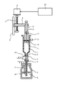
【図1】 本発明の液体充填装置の概略図である。
【図2】 従来の液体充填装置の概略図である。
【図3】 従来の液体充填装置の有する問題の説明図である。
【符号の説明】
1 液体貯留容器
2 圧力容器
3 液体取り出し口配管
4 液体吸入管
5 取り付け口
6 駆動部
7 ボールネジ
8 直動保持器
9 直動機構
10 プランジャー保持棒
11 プランジャー
12 弁
13 空気逃し用穴
14 圧力センサー
15 満量検知センサー
16 満量検知具
17 残量少検知センサー
18 残量少検知具
19 エアー加圧管
20 制御部
L 液体[0001]
[Technical field to which industry belongs]
The present invention relates to a technique for filling liquid into a liquid storage container related to all processes that require discharge and application processes of viscous fluids and liquids including viscous substances, such as electronic component manufacturing and electronic component assembly processes. .
[0002]
[Prior art]
In order to discharge a desired amount of liquid, a liquid fixed amount discharge device that discharges a liquid from a liquid storage container via a discharge valve is used. If to use a method of using or robot to move the nozzle adherend (work) is general. the more liquid medium viscosity example, filling liquid tank, especially to syringes, many 2 as shown, the liquid outlet pipe (3) is provided in advance the liquid (L) is filled the pressure vessel (2), a liquid storage container to the outlet of the outlet pipe (3) (1), especially connect a syringe to the airtight, through the liquid outlet pipe (3) filling the liquid into the syringe by pressurizing the air to liquid (L) in the pressure vessel (2).
[0003]
However, as shown in FIG. 3, the major problem with the prior art is that when the air is pressurized into the pressure vessel, the liquid is discharged into the syringe through the connecting port of the syringe through the outlet port, the liquid is discharged to the atmospheric pressure. Therefore, in particular, the higher the liquid viscosity is, the more the liquid is discharged and the liquid is buried in the syringe while entraining the bubbles so as to maintain the diameter of the syringe connection port inner diameter. This is because the syringe on the filling side is in an atmospheric pressure state, so that the liquid to be filled is in a free state.
[0004]
[Problems to be solved by the invention]
The present invention relates to a liquid quantitative discharge technique, and provides a method and apparatus for eliminating entrainment of bubbles when a liquid storage container, particularly a syringe, is filled with liquid. The present invention also provides a method and apparatus that eliminates the need for the operator to adjust the filling speed while monitoring during filling in order to eliminate the entrainment of bubbles. That is, the present invention provides a method and apparatus characterized by fully automatic filling.
[0005]
[Means for Solving the Problems]
In the present invention, when a liquid storage container is filled with a liquid from a pressure container in which liquid has been stored in advance, the liquid pressure in the liquid storage container is controlled to a constant pressure lower than the air pressure applied to the pressure container. The main point is a liquid filling method that automatically fills the liquid.
[0006]
The filling of the liquid storage container is detected and the filling is automatically stopped. Therefore, when the liquid storage container is filled with the liquid from the pressure container in which the liquid has been stored in advance, the liquid pressure in the liquid storage container is reduced. A liquid filling method that automatically controls filling without air bubbles being mixed, controlling the pressure to a certain level lower than the air pressure applied to the pressure vessel, detecting the full amount of the liquid storage container, and automatically stopping filling. It is a summary.
[0007]
When the remaining amount of the pressure vessel is detected and filling is automatically stopped, the present invention reduces the liquid pressure in the liquid storage container when filling the liquid storage container from the pressure vessel in which the liquid has been stored in advance. The pressure is controlled to a constant pressure lower than the air pressure applied to the pressure vessel, and when the remaining amount of the pressure vessel is detected, filling is automatically stopped, and when necessary, the full amount of the liquid storage vessel is detected and filling is automatically performed. The gist of the present invention is a liquid filling method in which bubbles are automatically filled without stopping.
[0008]
The bubbles generated unexpectedly in the liquid storage container are removed. Therefore, the present invention applies the liquid pressure in the liquid storage container to the pressure container when the liquid storage container is filled with the liquid from the pressure container in which the liquid has been stored in advance. The air pressure is controlled to a certain level lower than the compressed air pressure, air bubbles that occur unexpectedly in the liquid storage container are removed, and if necessary, the remaining amount of the pressure container is detected to stop filling automatically. The gist of the liquid filling method is to automatically stop filling by detecting the fullness of the container and automatically stopping the filling and / or detecting the remaining amount of the pressure container and stopping the filling automatically. Yes.
[0009]
The present invention also provides a liquid storage container including a plunger that is inserted in an airtight manner, a pressure container that stores liquid in advance, and a constant liquid pressure in the liquid storage container that is lower than the air pressure that is applied to the pressure container. The gist of the present invention is a filling device for a liquid storage container that has a plunger direct-acting control mechanism that maintains the pressure, and that can be automatically filled without bubbles.
[0010]
It has means for detecting the full capacity of the liquid storage container and / or means for detecting the low remaining amount of the pressure container, and the filling is automatically stopped by the detection signal. Therefore, the present invention inserts airtightly A liquid storage container having a plunger to be operated, a pressure container in which liquid is stored in advance, and a direct movement of the plunger that maintains a constant pressure lower than the air pressure in which the liquid pressure in the liquid storage container is pressurized to the pressure container It has a control mechanism, and further has means for detecting the full capacity of the liquid storage container and / or means for detecting the remaining amount of the pressure container, and automatically stops filling by the detection signal. The gist of the present invention is an apparatus for filling a liquid storage container that can be automatically filled.
[0011]
An air escape hole that communicates to the outside from the plunger inserted into the liquid storage container is provided, and a valve structure that can close the hole at any time is provided to remove bubbles that occur unexpectedly in the liquid storage container. Therefore, the present invention provides a liquid storage container having a plunger that is inserted in an airtight manner, a pressure container that stores liquid in advance, and air in which the liquid pressure in the liquid storage container is pressurized to the pressure container. A plunger direct-acting control mechanism that maintains a constant pressure lower than the pressure, and if necessary, means for detecting the full capacity of the liquid storage container and / or means for detecting the remaining amount of the pressure container. A valve structure that automatically stops filling with a detection signal and has a hole for air release that communicates from the plunger inserted into the liquid storage container to the outside, and can close the hole at any time. And setting, unexpected to be able to remove the bubbles generated in the liquid storage container, without inclusion of air bubbles, it is summarized as filling device to the liquid storage container which can be automatically filled.
[0012]
DETAILED DESCRIPTION OF THE INVENTION
As shown in FIG. 1, in the present invention, an airtight plunger is inserted in advance into a liquid storage container, and a linear motion mechanism is connected to the plunger. Further, the linear motion mechanism is connected with a drive unit such as a pulse motor that can perform forward / reverse operation by a control signal.
On the other hand, a liquid outlet of a pressure container (which may be a syringe) that stores liquid in advance is connected to the end of the liquid storage container, and a detection unit that measures pressure such as a pressure sensor is connected to the connected pipe. .
The detection means can send a detection signal to a control unit that sends a signal to the drive unit.
[0013]
The plunger is pushed when a forward rotation signal is sent to the drive unit. The plunger is pulled when a reverse rotation signal is sent to the drive unit . Go extruding liquid in the pressurized air to the pressure vessel. When detection instrument attached to the pressure vessel reaches a residual low level, and sends the remaining low signal remaining low sensor to the control unit. When the detector attached to the plunger on the liquid storage container side reaches the full level, the full sensor sends a full signal to the control unit. The pressure sensor in the liquid outlet piping always sends a measured pressure data signal to the control unit.
[0014]
[Action]
The present invention eliminates entrainment of bubbles when a liquid storage container, particularly a syringe, is filled with liquid. Moreover, in order to eliminate entrainment of bubbles, it is excluded that the operator adjusts the filling speed while monitoring during filling. A feature of the present invention is fully automatic filling. The present invention relates to a liquid dispensing technique.
In particular, a liquid storage container that can be applied to all work steps for filling a liquid having a medium viscosity or higher and that uses the liquid by pushing out from the end of the liquid storage container is preferable.
The liquid storage container filled with the liquid includes a liquid storage container, a liquid pressurizing unit for pressurizing the liquid stored in the liquid storage container with a pressure corresponding to the viscosity thereof, and a discharge valve communicating with the liquid storage container. The liquid storage container of the apparatus which discharges | quantitatively discharges the liquid from the provided liquid storage container through a discharge valve is comprised.
[0015]
【Example】
The details of the present invention will be described in the embodiment shown in FIG. 1, the present invention is not intended to be limited by this embodiment.
In the description, the same reference numerals are given to portions common to the conventional apparatus.
[0016]
Example As shown in FIG. 1, a liquid storage container (1) is connected to a liquid outlet pipe (3) . The plunger (11) is inserted into the liquid storage container (1 ) and connected to the linear motion mechanism (9) . The pressure vessel (2) filled with the liquid (L) in advance is connected to the liquid outlet. Pressurize the air into the pressure vessel (2) .
Liquid outlet pipe (3) Pressure Sensor (14) measures the pressure controller in the (20) sends a signal. Driver of the control unit (20) to the pre-set pressure subtracted value by subtracting to the signal from the pressure sensor over (14), the pressure data after subtraction, linear motion mechanism (9) (6 ) Is sent back, and the plunger (11) is pulled at a preset moving speed.
When a liquid outlet pipe (3) in the pressure Sensor (14) reaches the pressure value after the subtraction, by stopping the movement speed of the plunger (11), the pressure vessel a liquid pressure of the liquid storage container The air pressure is controlled to a constant pressure lower than the pressurized air pressure . Until the liquid container (1) to provided a liquid full amount detection sensor chromatography (15) is operated, automatically repeating the above operation. Alternatively, the filling operation is stopped even when the low remaining amount detection sensor (17 ) on the pressure vessel (2) side operates.
[0017]
【The invention's effect】
When a liquid storage container, particularly a syringe, is filled with a liquid, the entrainment of bubbles can be eliminated and the filling of the liquid can be automatically processed, so that the filling operation can be unmanned .
[Brief description of the drawings]
FIG. 1 is a schematic view of a liquid filling apparatus of the present invention.
FIG. 2 is a schematic view of a conventional liquid filling apparatus .
FIG. 3 is an explanatory view of a problem with a conventional liquid filling apparatus .
[Explanation of symbols]
DESCRIPTION OF
Claims (10)
液体貯留容器へ液体を充填する際に、液体圧力センサーで液体圧力を測定しながらプランジャーを直動して液体貯留容器内の液体圧力を圧力容器へ加圧されたエア圧より低い一定の圧力に制御することで、気泡の混入が無く、自動的に充填する液体充填方法。A liquid filling method for filling a liquid storage container with a liquid from a pressure container in which a liquid is stored in advance by directly moving a plunger inserted into the liquid storage container with a drive unit capable of performing forward and reverse operations ,
When filling the liquid storage container with a liquid, the liquid pressure sensor measures the liquid pressure, and the plunger is moved directly so that the liquid pressure in the liquid storage container is lower than the air pressure applied to the pressure container. by controlling the liquid filling method of bubbles is no, automatically filled.
Priority Applications (9)
| Application Number | Priority Date | Filing Date | Title |
|---|---|---|---|
| JP14964799A JP3948643B2 (en) | 1999-05-28 | 1999-05-28 | Liquid filling method and apparatus for liquid storage container |
| KR10-2001-7008240A KR100525720B1 (en) | 1998-12-28 | 1999-12-17 | Method and device for injecting a fixed quantity of liquid |
| PCT/JP1999/007099 WO2000040346A1 (en) | 1998-12-28 | 1999-12-17 | Method and device for injecting a fixed quantity of liquid |
| US09/868,630 US6715506B1 (en) | 1998-12-28 | 1999-12-17 | Method and device for injecting a fixed quantity of liquid |
| EP99959878.2A EP1155748B1 (en) | 1998-12-28 | 1999-12-17 | Method and device for injecting a fixed quantity of liquid |
| CNB998151017A CN100381213C (en) | 1998-12-28 | 1999-12-17 | Method and device for injecting fixed quantity of liquid |
| MYPI99005780A MY123349A (en) | 1998-12-28 | 1999-12-28 | Method and device for injecting a fixed quantity of liquid |
| TW88123100A TW416870B (en) | 1998-12-28 | 1999-12-28 | Method and apparatus for ejecting liquid in fixed amount |
| HK02105423.4A HK1043753B (en) | 1998-12-28 | 2002-07-23 | Method and device for injecting a fixed quantity of liquid |
Applications Claiming Priority (1)
| Application Number | Priority Date | Filing Date | Title |
|---|---|---|---|
| JP14964799A JP3948643B2 (en) | 1999-05-28 | 1999-05-28 | Liquid filling method and apparatus for liquid storage container |
Publications (3)
| Publication Number | Publication Date |
|---|---|
| JP2000335505A JP2000335505A (en) | 2000-12-05 |
| JP2000335505A5 JP2000335505A5 (en) | 2004-10-07 |
| JP3948643B2 true JP3948643B2 (en) | 2007-07-25 |
Family
ID=15479807
Family Applications (1)
| Application Number | Title | Priority Date | Filing Date |
|---|---|---|---|
| JP14964799A Expired - Lifetime JP3948643B2 (en) | 1998-12-28 | 1999-05-28 | Liquid filling method and apparatus for liquid storage container |
Country Status (1)
| Country | Link |
|---|---|
| JP (1) | JP3948643B2 (en) |
Cited By (1)
| Publication number | Priority date | Publication date | Assignee | Title |
|---|---|---|---|---|
| CN104494920A (en) * | 2014-12-20 | 2015-04-08 | 李立郎 | Quantitative viscous liquid filling equipment |
Families Citing this family (1)
| Publication number | Priority date | Publication date | Assignee | Title |
|---|---|---|---|---|
| JP5234709B2 (en) * | 2006-09-29 | 2013-07-10 | 株式会社アルバック | Liquid agent dropping device and defoaming method for liquid agent dropping device |
-
1999
- 1999-05-28 JP JP14964799A patent/JP3948643B2/en not_active Expired - Lifetime
Cited By (1)
| Publication number | Priority date | Publication date | Assignee | Title |
|---|---|---|---|---|
| CN104494920A (en) * | 2014-12-20 | 2015-04-08 | 李立郎 | Quantitative viscous liquid filling equipment |
Also Published As
| Publication number | Publication date |
|---|---|
| JP2000335505A (en) | 2000-12-05 |
Similar Documents
| Publication | Publication Date | Title |
|---|---|---|
| JP5100074B2 (en) | Pneumatic delivery system and method using linear actuation | |
| JPH0355791B2 (en) | ||
| JP3300121B2 (en) | Sampling device | |
| JP2000046846A (en) | Method for detecting clog of suction channel or suction amount insufficiency, sample liquid-sucking apparatus, and dispensing apparatus | |
| US6234356B1 (en) | Applicator and electro-mechanical applicator drive system | |
| US5665601A (en) | Avoiding bubble formation while sensing air-liquid interface using pressurized air flow | |
| JPH1135003A (en) | Filling nozzle, and liquid filling method | |
| AU2001240854A1 (en) | Continuous liquid flow system | |
| JP3948643B2 (en) | Liquid filling method and apparatus for liquid storage container | |
| JP4322282B2 (en) | Liquid supply device | |
| JP2008089181A (en) | Minute amount distribution device for liquid medium | |
| EP1649938B1 (en) | Liquid drop regulating method, liquid drop discharging method, and liquid drop discharging device | |
| JP3820025B2 (en) | Automatic dispensing device | |
| US9027789B2 (en) | Automated vacuum assisted valve priming system and methods of use | |
| JP3342841B2 (en) | Liquid metering method and apparatus | |
| JP2000335505A5 (en) | ||
| US7981078B2 (en) | Inflation/deflation system for a catheter | |
| CN115200655A (en) | Metering device and method for metering a liquid medium | |
| JPS58105066A (en) | Suction/discharge apparatus for automatic chemical analyzer | |
| JP2607591B2 (en) | Dispensing device | |
| JP4970794B2 (en) | Liquid preparation equipment | |
| JP2695609B2 (en) | Dispensing device | |
| JP2005227102A (en) | Dispenser | |
| JP3512515B2 (en) | Liquid dispensing device | |
| JP2007278835A (en) | Dispensing device and method |
Legal Events
| Date | Code | Title | Description |
|---|---|---|---|
| A131 | Notification of reasons for refusal |
Free format text: JAPANESE INTERMEDIATE CODE: A131 Effective date: 20060323 |
|
| A521 | Written amendment |
Free format text: JAPANESE INTERMEDIATE CODE: A821 Effective date: 20060518 Free format text: JAPANESE INTERMEDIATE CODE: A523 Effective date: 20060518 |
|
| RD02 | Notification of acceptance of power of attorney |
Free format text: JAPANESE INTERMEDIATE CODE: A7422 Effective date: 20060518 |
|
| TRDD | Decision of grant or rejection written | ||
| A01 | Written decision to grant a patent or to grant a registration (utility model) |
Free format text: JAPANESE INTERMEDIATE CODE: A01 Effective date: 20070412 |
|
| A61 | First payment of annual fees (during grant procedure) |
Free format text: JAPANESE INTERMEDIATE CODE: A61 Effective date: 20070413 |
|
| R150 | Certificate of patent or registration of utility model |
Free format text: JAPANESE INTERMEDIATE CODE: R150 |
|
| A521 | Written amendment |
Free format text: JAPANESE INTERMEDIATE CODE: A523 Effective date: 20030925 |
|
| FPAY | Renewal fee payment (event date is renewal date of database) |
Free format text: PAYMENT UNTIL: 20100427 Year of fee payment: 3 |
|
| FPAY | Renewal fee payment (event date is renewal date of database) |
Free format text: PAYMENT UNTIL: 20110427 Year of fee payment: 4 |
|
| FPAY | Renewal fee payment (event date is renewal date of database) |
Free format text: PAYMENT UNTIL: 20120427 Year of fee payment: 5 |
|
| FPAY | Renewal fee payment (event date is renewal date of database) |
Free format text: PAYMENT UNTIL: 20130427 Year of fee payment: 6 |
|
| FPAY | Renewal fee payment (event date is renewal date of database) |
Free format text: PAYMENT UNTIL: 20140427 Year of fee payment: 7 |
|
| R250 | Receipt of annual fees |
Free format text: JAPANESE INTERMEDIATE CODE: R250 |
|
| R250 | Receipt of annual fees |
Free format text: JAPANESE INTERMEDIATE CODE: R250 |
|
| R250 | Receipt of annual fees |
Free format text: JAPANESE INTERMEDIATE CODE: R250 |
|
| R250 | Receipt of annual fees |
Free format text: JAPANESE INTERMEDIATE CODE: R250 |
|
| R250 | Receipt of annual fees |
Free format text: JAPANESE INTERMEDIATE CODE: R250 |
|
| R250 | Receipt of annual fees |
Free format text: JAPANESE INTERMEDIATE CODE: R250 |
|
| EXPY | Cancellation because of completion of term |