JP3944649B2 - Liquid crystal display device and electronic device - Google Patents
Liquid crystal display device and electronic device Download PDFInfo
- Publication number
- JP3944649B2 JP3944649B2 JP2004031060A JP2004031060A JP3944649B2 JP 3944649 B2 JP3944649 B2 JP 3944649B2 JP 2004031060 A JP2004031060 A JP 2004031060A JP 2004031060 A JP2004031060 A JP 2004031060A JP 3944649 B2 JP3944649 B2 JP 3944649B2
- Authority
- JP
- Japan
- Prior art keywords
- liquid crystal
- dot
- area
- region
- display
- Prior art date
- Legal status (The legal status is an assumption and is not a legal conclusion. Google has not performed a legal analysis and makes no representation as to the accuracy of the status listed.)
- Expired - Lifetime
Links
- 239000004973 liquid crystal related substance Substances 0.000 title claims description 195
- 239000000758 substrate Substances 0.000 claims description 63
- 239000011159 matrix material Substances 0.000 claims description 13
- 239000010408 film Substances 0.000 description 77
- 230000004048 modification Effects 0.000 description 74
- 238000012986 modification Methods 0.000 description 74
- 230000005684 electric field Effects 0.000 description 14
- 230000001105 regulatory effect Effects 0.000 description 9
- 238000003491 array Methods 0.000 description 5
- 230000015572 biosynthetic process Effects 0.000 description 5
- 230000005540 biological transmission Effects 0.000 description 4
- 238000010586 diagram Methods 0.000 description 4
- 208000037265 diseases, disorders, signs and symptoms Diseases 0.000 description 4
- 230000000694 effects Effects 0.000 description 4
- 239000011521 glass Substances 0.000 description 4
- 238000000034 method Methods 0.000 description 4
- 239000004033 plastic Substances 0.000 description 4
- 239000010453 quartz Substances 0.000 description 4
- VYPSYNLAJGMNEJ-UHFFFAOYSA-N silicon dioxide Inorganic materials O=[Si]=O VYPSYNLAJGMNEJ-UHFFFAOYSA-N 0.000 description 4
- 229910052782 aluminium Inorganic materials 0.000 description 3
- 229910052751 metal Inorganic materials 0.000 description 3
- 239000002184 metal Substances 0.000 description 3
- 239000004925 Acrylic resin Substances 0.000 description 2
- 229920000178 Acrylic resin Polymers 0.000 description 2
- XAGFODPZIPBFFR-UHFFFAOYSA-N aluminium Chemical compound [Al] XAGFODPZIPBFFR-UHFFFAOYSA-N 0.000 description 2
- 239000003086 colorant Substances 0.000 description 2
- 210000002858 crystal cell Anatomy 0.000 description 2
- 229910052709 silver Inorganic materials 0.000 description 2
- 238000002834 transmittance Methods 0.000 description 2
- 206010047571 Visual impairment Diseases 0.000 description 1
- 210000004027 cell Anatomy 0.000 description 1
- 230000001276 controlling effect Effects 0.000 description 1
- 230000003247 decreasing effect Effects 0.000 description 1
- 230000007547 defect Effects 0.000 description 1
- AMGQUBHHOARCQH-UHFFFAOYSA-N indium;oxotin Chemical compound [In].[Sn]=O AMGQUBHHOARCQH-UHFFFAOYSA-N 0.000 description 1
- 238000010030 laminating Methods 0.000 description 1
- 239000000463 material Substances 0.000 description 1
- 230000003287 optical effect Effects 0.000 description 1
- 230000003071 parasitic effect Effects 0.000 description 1
- 230000002093 peripheral effect Effects 0.000 description 1
- 239000004332 silver Substances 0.000 description 1
- 239000010409 thin film Substances 0.000 description 1
Images


Classifications
-
- F—MECHANICAL ENGINEERING; LIGHTING; HEATING; WEAPONS; BLASTING
- F16—ENGINEERING ELEMENTS AND UNITS; GENERAL MEASURES FOR PRODUCING AND MAINTAINING EFFECTIVE FUNCTIONING OF MACHINES OR INSTALLATIONS; THERMAL INSULATION IN GENERAL
- F16L—PIPES; JOINTS OR FITTINGS FOR PIPES; SUPPORTS FOR PIPES, CABLES OR PROTECTIVE TUBING; MEANS FOR THERMAL INSULATION IN GENERAL
- F16L41/00—Branching pipes; Joining pipes to walls
- F16L41/08—Joining pipes to walls or pipes, the joined pipe axis being perpendicular to the plane of the wall or to the axis of another pipe
- F16L41/14—Joining pipes to walls or pipes, the joined pipe axis being perpendicular to the plane of the wall or to the axis of another pipe by screwing an intermediate part against the inside or outside of the wall
-
- G—PHYSICS
- G02—OPTICS
- G02F—OPTICAL DEVICES OR ARRANGEMENTS FOR THE CONTROL OF LIGHT BY MODIFICATION OF THE OPTICAL PROPERTIES OF THE MEDIA OF THE ELEMENTS INVOLVED THEREIN; NON-LINEAR OPTICS; FREQUENCY-CHANGING OF LIGHT; OPTICAL LOGIC ELEMENTS; OPTICAL ANALOGUE/DIGITAL CONVERTERS
- G02F1/00—Devices or arrangements for the control of the intensity, colour, phase, polarisation or direction of light arriving from an independent light source, e.g. switching, gating or modulating; Non-linear optics
- G02F1/01—Devices or arrangements for the control of the intensity, colour, phase, polarisation or direction of light arriving from an independent light source, e.g. switching, gating or modulating; Non-linear optics for the control of the intensity, phase, polarisation or colour
- G02F1/13—Devices or arrangements for the control of the intensity, colour, phase, polarisation or direction of light arriving from an independent light source, e.g. switching, gating or modulating; Non-linear optics for the control of the intensity, phase, polarisation or colour based on liquid crystals, e.g. single liquid crystal display cells
- G02F1/133—Constructional arrangements; Operation of liquid crystal cells; Circuit arrangements
- G02F1/1333—Constructional arrangements; Manufacturing methods
- G02F1/1337—Surface-induced orientation of the liquid crystal molecules, e.g. by alignment layers
- G02F1/133753—Surface-induced orientation of the liquid crystal molecules, e.g. by alignment layers with different alignment orientations or pretilt angles on a same surface, e.g. for grey scale or improved viewing angle
-
- F—MECHANICAL ENGINEERING; LIGHTING; HEATING; WEAPONS; BLASTING
- F16—ENGINEERING ELEMENTS AND UNITS; GENERAL MEASURES FOR PRODUCING AND MAINTAINING EFFECTIVE FUNCTIONING OF MACHINES OR INSTALLATIONS; THERMAL INSULATION IN GENERAL
- F16L—PIPES; JOINTS OR FITTINGS FOR PIPES; SUPPORTS FOR PIPES, CABLES OR PROTECTIVE TUBING; MEANS FOR THERMAL INSULATION IN GENERAL
- F16L41/00—Branching pipes; Joining pipes to walls
- F16L41/08—Joining pipes to walls or pipes, the joined pipe axis being perpendicular to the plane of the wall or to the axis of another pipe
- F16L41/16—Joining pipes to walls or pipes, the joined pipe axis being perpendicular to the plane of the wall or to the axis of another pipe the branch pipe comprising fluid cut-off means
-
- G—PHYSICS
- G02—OPTICS
- G02F—OPTICAL DEVICES OR ARRANGEMENTS FOR THE CONTROL OF LIGHT BY MODIFICATION OF THE OPTICAL PROPERTIES OF THE MEDIA OF THE ELEMENTS INVOLVED THEREIN; NON-LINEAR OPTICS; FREQUENCY-CHANGING OF LIGHT; OPTICAL LOGIC ELEMENTS; OPTICAL ANALOGUE/DIGITAL CONVERTERS
- G02F1/00—Devices or arrangements for the control of the intensity, colour, phase, polarisation or direction of light arriving from an independent light source, e.g. switching, gating or modulating; Non-linear optics
- G02F1/01—Devices or arrangements for the control of the intensity, colour, phase, polarisation or direction of light arriving from an independent light source, e.g. switching, gating or modulating; Non-linear optics for the control of the intensity, phase, polarisation or colour
- G02F1/13—Devices or arrangements for the control of the intensity, colour, phase, polarisation or direction of light arriving from an independent light source, e.g. switching, gating or modulating; Non-linear optics for the control of the intensity, phase, polarisation or colour based on liquid crystals, e.g. single liquid crystal display cells
- G02F1/133—Constructional arrangements; Operation of liquid crystal cells; Circuit arrangements
- G02F1/1333—Constructional arrangements; Manufacturing methods
- G02F1/133371—Cells with varying thickness of the liquid crystal layer
-
- G—PHYSICS
- G02—OPTICS
- G02F—OPTICAL DEVICES OR ARRANGEMENTS FOR THE CONTROL OF LIGHT BY MODIFICATION OF THE OPTICAL PROPERTIES OF THE MEDIA OF THE ELEMENTS INVOLVED THEREIN; NON-LINEAR OPTICS; FREQUENCY-CHANGING OF LIGHT; OPTICAL LOGIC ELEMENTS; OPTICAL ANALOGUE/DIGITAL CONVERTERS
- G02F1/00—Devices or arrangements for the control of the intensity, colour, phase, polarisation or direction of light arriving from an independent light source, e.g. switching, gating or modulating; Non-linear optics
- G02F1/01—Devices or arrangements for the control of the intensity, colour, phase, polarisation or direction of light arriving from an independent light source, e.g. switching, gating or modulating; Non-linear optics for the control of the intensity, phase, polarisation or colour
- G02F1/13—Devices or arrangements for the control of the intensity, colour, phase, polarisation or direction of light arriving from an independent light source, e.g. switching, gating or modulating; Non-linear optics for the control of the intensity, phase, polarisation or colour based on liquid crystals, e.g. single liquid crystal display cells
- G02F1/133—Constructional arrangements; Operation of liquid crystal cells; Circuit arrangements
- G02F1/1333—Constructional arrangements; Manufacturing methods
- G02F1/1337—Surface-induced orientation of the liquid crystal molecules, e.g. by alignment layers
- G02F1/133707—Structures for producing distorted electric fields, e.g. bumps, protrusions, recesses, slits in pixel electrodes
-
- G—PHYSICS
- G02—OPTICS
- G02F—OPTICAL DEVICES OR ARRANGEMENTS FOR THE CONTROL OF LIGHT BY MODIFICATION OF THE OPTICAL PROPERTIES OF THE MEDIA OF THE ELEMENTS INVOLVED THEREIN; NON-LINEAR OPTICS; FREQUENCY-CHANGING OF LIGHT; OPTICAL LOGIC ELEMENTS; OPTICAL ANALOGUE/DIGITAL CONVERTERS
- G02F1/00—Devices or arrangements for the control of the intensity, colour, phase, polarisation or direction of light arriving from an independent light source, e.g. switching, gating or modulating; Non-linear optics
- G02F1/01—Devices or arrangements for the control of the intensity, colour, phase, polarisation or direction of light arriving from an independent light source, e.g. switching, gating or modulating; Non-linear optics for the control of the intensity, phase, polarisation or colour
- G02F1/13—Devices or arrangements for the control of the intensity, colour, phase, polarisation or direction of light arriving from an independent light source, e.g. switching, gating or modulating; Non-linear optics for the control of the intensity, phase, polarisation or colour based on liquid crystals, e.g. single liquid crystal display cells
- G02F1/137—Devices or arrangements for the control of the intensity, colour, phase, polarisation or direction of light arriving from an independent light source, e.g. switching, gating or modulating; Non-linear optics for the control of the intensity, phase, polarisation or colour based on liquid crystals, e.g. single liquid crystal display cells characterised by the electro-optical or magneto-optical effect, e.g. field-induced phase transition, orientation effect, guest-host interaction or dynamic scattering
- G02F1/139—Devices or arrangements for the control of the intensity, colour, phase, polarisation or direction of light arriving from an independent light source, e.g. switching, gating or modulating; Non-linear optics for the control of the intensity, phase, polarisation or colour based on liquid crystals, e.g. single liquid crystal display cells characterised by the electro-optical or magneto-optical effect, e.g. field-induced phase transition, orientation effect, guest-host interaction or dynamic scattering based on orientation effects in which the liquid crystal remains transparent
- G02F1/1393—Devices or arrangements for the control of the intensity, colour, phase, polarisation or direction of light arriving from an independent light source, e.g. switching, gating or modulating; Non-linear optics for the control of the intensity, phase, polarisation or colour based on liquid crystals, e.g. single liquid crystal display cells characterised by the electro-optical or magneto-optical effect, e.g. field-induced phase transition, orientation effect, guest-host interaction or dynamic scattering based on orientation effects in which the liquid crystal remains transparent the birefringence of the liquid crystal being electrically controlled, e.g. ECB-, DAP-, HAN-, PI-LC cells
-
- G—PHYSICS
- G02—OPTICS
- G02F—OPTICAL DEVICES OR ARRANGEMENTS FOR THE CONTROL OF LIGHT BY MODIFICATION OF THE OPTICAL PROPERTIES OF THE MEDIA OF THE ELEMENTS INVOLVED THEREIN; NON-LINEAR OPTICS; FREQUENCY-CHANGING OF LIGHT; OPTICAL LOGIC ELEMENTS; OPTICAL ANALOGUE/DIGITAL CONVERTERS
- G02F2203/00—Function characteristic
- G02F2203/09—Function characteristic transflective
Landscapes
- Physics & Mathematics (AREA)
- Nonlinear Science (AREA)
- Engineering & Computer Science (AREA)
- General Engineering & Computer Science (AREA)
- Mathematical Physics (AREA)
- Chemical & Material Sciences (AREA)
- Crystallography & Structural Chemistry (AREA)
- General Physics & Mathematics (AREA)
- Optics & Photonics (AREA)
- Mechanical Engineering (AREA)
- Spectroscopy & Molecular Physics (AREA)
- Liquid Crystal (AREA)
Description
本発明は、液晶表示装置及び電子機器に関し、特に反射モードと透過モードの双方で表示を行う半透過反射型の液晶表示装置において、高輝度、高コントラスト、広視野角の表示が得られる技術に関するものである。 The present invention relates to a liquid crystal display device and an electronic apparatus, and more particularly to a technique capable of obtaining a display with high brightness, high contrast, and a wide viewing angle in a transflective liquid crystal display device that performs display in both a reflection mode and a transmission mode. Is.
明るい場所では反射型液晶表示装置と同様に外光を利用し、暗い場所ではバックライト等の内部光源により表示を視認可能にした液晶表示装置が提案されている。つまり、この液晶表示装置は、反射型と透過型を兼ね備えた表示方式を採用しており、周囲の明るさに応じて反射モード、透過モードのいずれかの表示方式に切り替えることで消費電力を低減しつつ周囲が暗い場合でも明瞭な表示を行うことができ、携帯機器の表示部に好適なものである。以下、本明細書では、この種の液晶表示装置のことを「半透過反射型液晶表示装置」という。 A liquid crystal display device has been proposed in which external light is used in a bright place in the same manner as a reflective liquid crystal display device, and in a dark place, the display can be visually recognized by an internal light source such as a backlight. In other words, this liquid crystal display device employs a display method that combines a reflective type and a transmissive type, and reduces power consumption by switching to either the reflective mode or the transmissive mode depending on the ambient brightness. However, a clear display can be performed even when the surrounding is dark, which is suitable for a display portion of a portable device. Hereinafter, in this specification, this type of liquid crystal display device is referred to as a “transflective liquid crystal display device”.
このような半透過反射型液晶表示装置としては、上基板と下基板との間に液晶層が挟持されるとともに、例えばアルミニウム等の金属膜に光透過用の開口部を形成した反射膜を下基板の内面に備え、この反射膜を半透過反射板として機能させる液晶表示装置が提案されている。この場合、反射モードでは上基板側から入射した外光が、液晶層を通過した後に下基板の内面の反射膜で反射され、再び液晶層を通過して上基板側から出射され、表示に寄与する。一方、透過モードでは下基板側から入射したバックライトからの光が、反射膜の開口部から液晶層を通過した後、上基板側から外部に出射され、表示に寄与する。したがって、反射膜の形成領域のうち、開口部が形成された領域が透過表示領域、その他の領域が反射表示領域となる。 In such a transflective liquid crystal display device, a liquid crystal layer is sandwiched between an upper substrate and a lower substrate, and a reflective film in which an opening for light transmission is formed in a metal film such as aluminum is disposed below. There has been proposed a liquid crystal display device which is provided on the inner surface of a substrate and which functions as a transflective plate. In this case, in the reflection mode, external light incident from the upper substrate side passes through the liquid crystal layer, is reflected by the reflective film on the inner surface of the lower substrate, passes through the liquid crystal layer again, and is emitted from the upper substrate side, contributing to display. To do. On the other hand, in the transmissive mode, light from the backlight incident from the lower substrate side passes through the liquid crystal layer from the opening of the reflective film, and then is emitted to the outside from the upper substrate side, contributing to display. Therefore, of the reflective film formation region, the region where the opening is formed is the transmissive display region, and the other region is the reflective display region.
ところが、従来の半透過反射型液晶表示装置には、透過表示での視角が狭いという課題があった。これは、視差が生じないよう液晶セルの内面に半透過反射板を設けている関係で、観察者側に備えた1枚の偏光板だけで反射表示を行わなければならないという制約があり、光学設計の自由度が小さいためである。そこで、この課題を解決するために、特許文献1では、垂直配向液晶を用いる新しい半透過反射型液晶表示装置が提案されている。その特徴は、以下の3点である。
(1)誘電異方性が負の液晶を基板に対して垂直に配向させ、電圧印加によってこれを倒す「VA(Vertical Alignment)モード」を採用している点。
(2)透過表示領域と反射表示領域の液晶層厚(セルギャップ)が異なる「マルチギャップ構造」を採用している点。
(3)透過表示領域を正八角形又は円とし、この領域内で液晶が等方的に倒れるように対向基板上の透過表示領域の中央に突起を設けている点。すなわち、「配向分割構造」を採用している点。
However, the conventional transflective liquid crystal display device has a problem that the viewing angle in transmissive display is narrow. This is because a transflective plate is provided on the inner surface of the liquid crystal cell so that parallax does not occur, and there is a limitation that reflection display must be performed with only one polarizing plate provided on the viewer side. This is because the degree of freedom in design is small. Therefore, in order to solve this problem,
(1) Employs a “VA (Vertical Alignment) mode” in which a liquid crystal having a negative dielectric anisotropy is aligned perpendicularly to the substrate and then tilted by applying a voltage.
(2) A “multi-gap structure” is adopted in which the liquid crystal layer thickness (cell gap) is different between the transmissive display area and the reflective display area.
(3) The transmissive display area is a regular octagon or a circle, and a protrusion is provided at the center of the transmissive display area on the counter substrate so that the liquid crystal isotropically falls within this area. In other words, “alignment division structure” is adopted.
一方、透過型カラー液晶表示装置では、垂直配向モードを採用し様々な形状の電極スリット,突起等の配向制御手段を設けることによりマルチドメイン化し、広視野角を実現する方法が知られている(例えば、特許文献2〜4)。 On the other hand, in a transmissive color liquid crystal display device, a method for realizing a wide viewing angle by adopting a vertical alignment mode and providing alignment control means such as electrode slits and protrusions of various shapes is known ( For example, Patent Documents 2 to 4).
しかしながら、電極スリットや突起での配向制御ではその部分の液晶を完全に倒すことが難しいため、透過率が低くなるという問題があった。これは、配向制御手段を複雑にしてスリットや突起の占める面積を多くすれば一層その影響は強くなる。また、マルチギャップ構造の形成されたアレイ基板に電極スリットを形成する場合には、そのスリットの加工が難しく断線等が生じる虞がある。 However, since it is difficult to completely tilt the liquid crystal in the alignment control with the electrode slits and protrusions, there is a problem that the transmittance is lowered. This effect becomes even stronger if the orientation control means is complicated and the area occupied by the slits and protrusions is increased. In addition, when an electrode slit is formed on an array substrate having a multi-gap structure, it is difficult to process the slit, and there is a possibility that disconnection or the like may occur.
本発明は、上記の課題を解決するためになされたものであって、半透過反射型液晶表示装置において、残像等の表示不良が抑えられ、さらには高輝度化、高コントラスト化が可能な液晶表示装置を提供することを目的とする。 The present invention has been made in order to solve the above-described problem, and in a transflective liquid crystal display device, a display defect such as an afterimage is suppressed, and further, a liquid crystal capable of increasing brightness and increasing contrast. An object is to provide a display device.
上記の目的を達成するために、本発明の液晶表示装置は、誘電異方性が負の液晶からなる液晶層が一対の基板間に挟持され、透過表示を行なう透過表示領域と反射表示を行なう反射表示領域とからなる略矩形のドット領域が、画像表示領域内に複数マトリクス状に配列形成され、複数の前記ドット領域のうち第一のドット領域は、少なくとも該第一のドット領域の短辺に沿う方向と長辺に沿う方向のいずれか一方の方向に該第一のドット領域に隣接する第二のドット領域と第三のドット領域とに挟まれており、前記第一のドット領域と前記第二のドット領域との間には第一のドット間領域を有し、前記第一のドット領域と前記第三のドット領域との間には第二のドット間領域を有し、前記第一のドット領域と前記第二のドット領域の透過表示領域は前記第一のドット間領域を挟んで対向配置され、前記第一のドット領域と前記第三のドット領域の反射表示領域は前記第二のドット間領域を挟んで対向配置されたことを特徴とする。
In order to achieve the above object, a liquid crystal display device according to the present invention has a liquid crystal layer composed of a liquid crystal having negative dielectric anisotropy sandwiched between a pair of substrates, and performs a transmissive display region for performing transmissive display and a reflective display. A substantially rectangular dot area composed of a reflective display area is arranged in a matrix in the image display area, and the first dot area of the plurality of dot areas is at least the short side of the first dot area Between the second dot region and the third dot region adjacent to the first dot region in either one of the direction along the long side and the direction along the long side, and the first dot region Between the second dot region has a first inter-dot region, between the first dot region and the third dot region has a second inter-dot region, Transparent display of the first dot area and the second dot area The areas are arranged opposite to each other across the first inter-dot area, and the reflective display areas of the first dot area and the third dot area are arranged opposite to each other across the second inter-dot area. Features.
なお、本発明の液晶表示装置は垂直配向モードを採用する以外、その構造は特に限定されず、単純マトリクス型、アクティブマトリクス型のいずれの構造を採用してもよい。また、前記一対の基板のうちのいずれか一方の基板の内面にカラーフィルタを設けてカラー表示を行なってもよい。 Note that the structure of the liquid crystal display device of the present invention is not particularly limited except that the vertical alignment mode is adopted, and either a simple matrix type or an active matrix type may be adopted. Further, color display may be performed by providing a color filter on the inner surface of one of the pair of substrates.
本発明の電子機器は上述の液晶表示装置を備えたことを特徴とする。この構成によれば、使用環境によらずに明るく、高輝度、高コントラスト、広視野角の液晶表示部を備えた電子機器を提供することができる。 An electronic apparatus according to the present invention includes the above-described liquid crystal display device. According to this configuration, it is possible to provide an electronic device including a liquid crystal display unit that is bright, has high brightness, high contrast, and a wide viewing angle regardless of the use environment.
[第1実施形態]
以下、図1〜図5を参照しながら本発明の第1実施形態に係る液晶表示装置について説明する。図1は本実施形態の液晶表示装置の概略構成を示す斜視図、図2はその要部平面図、図3はその要部断面図、図4はその作用を説明するための断面図、図5は液晶分子の配向状態を示す平面図である。なお、以下の各図においては、各層や各部材を図面上で認識可能な程度の大きさとするため、各層や各部材毎に縮尺を異ならせてある。また、本明細書では、液晶装置を構成する各部材において液晶層側に配置された面を「内面」、それと反対側の面を「外面」という。
[First Embodiment]
Hereinafter, a liquid crystal display device according to a first embodiment of the present invention will be described with reference to FIGS. 1 is a perspective view showing a schematic configuration of a liquid crystal display device according to the present embodiment, FIG. 2 is a plan view of the main part thereof, FIG. 3 is a cross-sectional view of the main part thereof, and FIG. 4 is a cross-sectional view for explaining the operation. 5 is a plan view showing the alignment state of liquid crystal molecules. In each of the following drawings, the scale of each layer and each member is different in order to make each layer and each member recognizable on the drawing. Further, in this specification, a surface disposed on the liquid crystal layer side in each member constituting the liquid crystal device is referred to as an “inner surface”, and a surface on the opposite side is referred to as an “outer surface”.
まず、図1,図2に基づいて本実施形態の液晶表示装置の概略構成について説明する。
本実施形態の液晶表示装置は単純マトリクス型の液晶表示装置であり、基板110,120には、それぞれ電極113,123がストライプ状に複数配列形成されている。電極113,123はそれぞれX方向、Y方向に延在して設けられ、これらの交差する略矩形の領域によって1つのドット領域が構成される。そして、このドット領域がマトリクス状に複数配列して画像表示領域が構成される。なお、図2において電極113間及び電極123間の領域をそれぞれ符号E1,E2で示しており、各ドット領域は平面視でこれらの領域E1,E2によって区画された状態となっている。
First, a schematic configuration of the liquid crystal display device of the present embodiment will be described with reference to FIGS.
The liquid crystal display device of this embodiment is a simple matrix type liquid crystal display device, and a plurality of
下基板110と下電極113との間には反射膜111が設けられており、1ドット領域においてこの反射膜111の形成された領域が反射表示領域Rとなり、それ以外の領域が透過表示領域Tとなる。この反射膜111はX方向に延在して設けられるとともにY方向に複数配列形成されており、上述の下電極113は対応する反射膜111を覆う形で形成されている。なお、反射膜111のY方向の幅は透過表示領域Tと反射表示領域Rの開口比率に応じて任意に設定できるが、透過表示領域と反射表示領域とを略同じ大きさとする場合には、その幅は下電極113のY方向の幅の半分程度に設定される。
A
また、本実施形態では、X方向に隣接するドット領域の透過表示領域T同士又は反射表示領域R同士が領域E1を挟んで対置されるように、反射膜111は領域E1を挟む位置に対を成して形成されている。つまり、領域E1を挟んでX方向に隣接する2つのドット領域を擬似的に1つのグループ領域とみた場合に、下基板110にはこのグループ領域が領域E1及び領域E2を挟んでX方向及びY方向複数配列形成された状態となっており、各グループ領域のX方向における両端部にそれぞれ反射膜111が配置されている。これにより、グループ領域のX方向における中央部には領域E1を挟む位置に2つの透過表示領域Tが形成され、グループ領域のX方向における両側部には2つの反射表示領域Rが形成される。
In the present embodiment, the
また、上基板120と電極123との間にはカラーフィルタ121R(赤),121G(緑),121B(青)からなるカラーフィルタ層121が設けられている。これらのカラーフィルタ121R〜121BはそれぞれX方向にストライプ状に複数配列形成されており、上述の上電極123は対応するカラーフィルタを覆う形で形成されている。
また、下基板110の外面側にはバックライト150が配置されている。
A
A
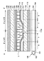
次に、図3に基づいて本液晶表示装置の断面構造について説明する。図3は図2のA−A′線に沿う2ドットの断面図であり、上述したグループ領域の断面構造を示している。
図3に示すように、下基板110とこれに対向配置された上基板120との間には、初期配向状態が垂直配向状態を呈する誘電異方性が負の液晶からなる液晶層130が挟持されている。
Next, a cross-sectional structure of the present liquid crystal display device will be described with reference to FIG. FIG. 3 is a cross-sectional view of 2 dots along the line AA ′ in FIG. 2 and shows the cross-sectional structure of the group region described above.
As shown in FIG. 3, a
ガラス,石英,プラスチック等の透光性部材からなる下基板110の上にはAl(アルミニウム),Ag(銀)等の高反射率の金属反射膜111が形成されている。上述したように、反射膜111の形成領域が反射表示領域Rとなり、反射膜111の非形成領域が透過表示領域Tとなる。
On a
基板110の上には、反射表示領域Rに対応する位置に液晶層の層厚を薄くするような厚みを有した絶縁膜112が形成されている。絶縁膜112は例えば膜厚が2μm±1μm程度のアクリル樹脂等の有機膜からなり、反射表示領域Rと透過表示領域Tとの境界付近において、自身の層厚が連続的に変化するべく傾斜面112aを有している。絶縁膜112が存在しない部分の液晶層130の厚みが2〜6μm程度であるから、反射表示領域Rにおける液晶層130の厚みは透過表示領域Tにおける液晶層130の厚みの約半分となる。つまり、絶縁膜112は、自身の膜厚によって反射表示領域Rと透過表示領域Tとの液晶層130の層厚を異ならせる液晶層厚調整層として機能している。
On the
本実施の形態の場合、絶縁膜112の上部の平坦面の縁と反射膜111(反射表示領域)の縁とが略一致しており、傾斜面112aは透過表示領域Tに含まれることになる。また、液晶層厚調整層は反射表示領域Rに対応して厚く形成されるものであるが、透過表示領域Tにも薄く形成されて存在する場合もある。また、本実施例では反射膜111を絶縁膜112(反射表示領域に対応した液晶層厚調整層)の下に形成したが、絶縁膜112の平坦面上、即ち絶縁膜112と透明導電膜からなる下電極113との間に設けてもよい。従って、反射表示領域Rに対応した絶縁膜112とは、透過表示領域Tより反射表示領域Rの液晶層の層厚を薄くさせている(或いは、透過表示領域Tにおける層厚より反射表示領域Rにおける層厚を厚くした)絶縁膜を示すものである。
In the case of the present embodiment, the edge of the flat surface above the insulating
そして、絶縁膜112の表面を含む基板110の表面には、ITO(インジウム錫酸化物)等の透明導電膜からなる下電極113と垂直配向膜114とが順次形成されている。
A
一方、ガラス,石英,プラスチック等の透光性部材からなる上基板120の内面側にはカラーフィルタ層121が設けられている。このカラーフィルタ層121は、隣接するドット領域毎に赤(R)、緑(G)、青(B)の異なる色のカラーフィルタ121R,121G,121Bが配置されており、隣接する3つのドット領域で1つの画素を構成する。あるいは、反射表示と透過表示とで表示色の彩度が異なるのを補償すべく、反射表示領域Rと透過表示領域Tとで色純度を変えたカラーフィルタを別個に設けてもよい。そして、このカラーフィルタ層121の上には、ITO等の透明導電膜からなる上電極123と垂直配向膜124とが順次形成されている。
On the other hand, a
また、下基板110の外面側、及び、上基板120の外面側には、それぞれ基板側から位相差板(円偏光入射手段)115,125、偏光板116,126が設けられている。位相差板115,125は可視光の波長に対して略1/4波長の位相差を持つものであり、この位相差板115,125と偏光板116,126との組み合わせにより基板110側及び基板120側の双方から液晶層130に円偏光が入射されるようになっている。また、基板110の外面側にあたる液晶セルの外側には、光源151,リフレクタ152,導光板153,反射板154等を有するバックライト150が設置されている。
Further, on the outer surface side of the
次に、図4,図5に基づいて本液晶表示装置の動作について説明する。図4(a),図4(b)はそれぞれ電圧印加状態における図2のA−A′線及びB−B′線に沿う位置の液晶の配向状態を示す図である。なお、図4では電極113,123のエッジ部113a,123aに生じる斜め電界を一点鎖線で示している。
Next, the operation of the present liquid crystal display device will be described with reference to FIGS. 4A and 4B are diagrams showing the alignment state of the liquid crystal at positions along the lines AA ′ and BB ′ of FIG. 2 in a voltage application state, respectively. In FIG. 4, the oblique electric field generated at the
上述の構成において電極113,123間に電圧を印加すると、領域E1近傍に位置する液晶分子Lは、図4(a)に示すように、下電極113のエッジ部113aに生じる斜め電界によりこのエッジ部113aから電極中央部(即ちドット中央部)に向けて傾斜配向する。そして、周囲の液晶分子Lはそれに倣ってドット中央部に向けて傾斜配向される。同様に、領域E2近傍に位置する液晶分子Lは、図4(b)に示すように、上電極123のエッジ部123aに生じる斜め電界によりこのエッジ部123aから電極中央部(即ちドット中央部)に向けて傾斜配向し、それに倣って周囲の液晶分子Lがドット中央部に向けて傾斜配向される。
When a voltage is applied between the
このため、図5に示すように、例えば領域E1を挟んでX方向に隣接するドット領域P1,P2では、それぞれの透過表示領域Tに位置する液晶分子Lは互いに逆向きに傾斜配向することとなる。同様のことは反射表示領域Rでも生じ、ドット領域P1,P2のそれぞれの反射表示領域Rに位置する液晶分子Lは互いに逆向きに傾斜配向される。 For this reason, as shown in FIG. 5, for example, in the dot regions P1 and P2 adjacent in the X direction across the region E1, the liquid crystal molecules L positioned in the respective transmissive display regions T are inclined and oriented in opposite directions. Become. The same thing occurs in the reflective display region R, and the liquid crystal molecules L positioned in the reflective display region R of the dot regions P1 and P2 are inclined and oriented in opposite directions.
すなわち、ドット領域P1,P2によって構成された1つのグループ領域内の透過表示領域T及び反射表示領域Rは共に配向分割された状態となる。同様に、領域E2を挟んでY方向に隣接する2つのドット領域からなるグループ領域内の透過表示領域T及び反射表示領域Rも共に配向分割された状態となる。 That is, the transmissive display area T and the reflective display area R in one group area constituted by the dot areas P1 and P2 are both in an orientation-divided state. Similarly, both the transmissive display area T and the reflective display area R in the group area composed of two dot areas adjacent in the Y direction across the area E2 are also in an orientation-divided state.
このように本実施形態では、電極の形成されないドット間の領域を従来の電極スリットとみなし、電圧印加時にドットのエッジに生じる斜め電界の作用により液晶の配向方向を制御している。このため、電極スリット等を別途設ける従来のものに比べて開口率が高く高輝度,高コントラストな表示が可能となる。特に本実施形態では、隣接するドットの透過表示領域T同士又は反射表示領域R同士をドット間の領域E1又はE2を挟んで対置しているため、上述のように電圧印加状態においてこれらの領域T,Rの液晶分子Lを互いに逆向きに倒すことができる。これにより、液晶層130は領域E1又はE2を挟んで2ドットに跨る領域で配向分割された状態となり、広視野角な表示が実現される。つまり、隣接する2つのドット領域では略同じ表示が行なわれるため、これらを擬似的に1つのドットのように扱うことができるが、本実施形態では、この擬似的に設定された1つのドット領域内の液晶を2方向に配向分割できるため、視野角特性を向上できる。
As described above, in this embodiment, the region between the dots where no electrode is formed is regarded as a conventional electrode slit, and the alignment direction of the liquid crystal is controlled by the action of the oblique electric field generated at the edge of the dot when a voltage is applied. Therefore, a display with a high aperture ratio and high luminance and high contrast is possible as compared with a conventional device in which an electrode slit or the like is separately provided. In particular, in the present embodiment, the transmissive display areas T of adjacent dots or the reflective display areas R are opposed to each other with the area E1 or E2 between the dots interposed therebetween. , R liquid crystal molecules L can be tilted in opposite directions. As a result, the
また、本実施形態では液晶層厚調整層112によって反射表示領域Rと透過表示領域Tとの液晶層厚を異ならせているため、反射表示領域Rにおけるリタデーションと透過表示領域Tにおけるリタデーションとを十分に近づけることができる、若しくは略等しくすることができ、これによりコントラストの向上を図ることができる。特に本実施形態では液晶層厚調整層112に傾斜面112aを設けているため、傾斜面近傍の液晶分子に対してこの傾斜角度に応じたプレチルトを付与することが可能となる。このため、この傾斜面近傍の液晶の傾倒に合わせて周囲の液晶の傾倒方向が規定されることで、配向乱れ(ディスクリネーション)が無秩序に生じることを防止でき、ザラツキ感の少ない鮮明な表示を実現できる。
In the present embodiment, the liquid crystal layer
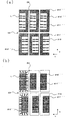
[変形例]
次に、図6,図7(a),(b)を参照しながら上記第1実施形態の変形例に係る液晶表示装置について説明する。図6,図7(a),(b)はそれぞれ上記第1実施形態の第1変形例,第2変形例,第3変形例に係る液晶表示装置における液晶の配向状態を示す平面図であり、図5に対応する図である。これらの変形例は、上記第1実施形態において反射膜及び液晶層厚調整層の配置を変形したものである。なお、本変形例において上記第1実施形態と同様の部材については同じ符号を付し、その説明を省略する。
[Modification]
Next, a liquid crystal display device according to a modification of the first embodiment will be described with reference to FIGS. 6 and 7A and 7B. FIGS. 6, 7A, and 7B are plan views showing the alignment state of the liquid crystal in the liquid crystal display devices according to the first, second, and third modifications of the first embodiment, respectively. FIG. 6 is a diagram corresponding to FIG. 5. These modified examples are obtained by modifying the arrangement of the reflective film and the liquid crystal layer thickness adjusting layer in the first embodiment. In addition, in this modification, the same code | symbol is attached | subjected about the member similar to the said 1st Embodiment, and the description is abbreviate | omitted.
まず、図6を参照しながら第1変形例について説明する。
図6(a)に示すように、本変形例では、反射膜111′はX方向に延在して設けられるとともにY方向に複数配列形成されている。この反射膜111′のY方向の幅は、透過表示領域Tと反射表示領域Rの開口比率に応じて任意に設定できるが、本変形例では例えば上電極123のY方向の幅の半分程度に設定されている。
First, a first modification will be described with reference to FIG.
As shown in FIG. 6A, in this modification, the
また、本変形例では、Y方向に隣接するドット領域の透過表示領域T同士又は反射表示領域R同士が領域E2を挟んで対置されるように、反射膜111′は領域E2を挟む位置に対を成して形成されている。つまり、領域E2を挟んでY方向に隣接する2つのドット領域を擬似的に1つのグループ領域とみた場合に、下基板110にはこのグループ領域が領域E1及び領域E2を挟んでX方向及びY方向に複数配列形成された状態となっており、各グループ領域のY方向における両端部にそれぞれ反射膜111′が配置されている。これにより、グループ領域のY方向における中央部には領域E2を挟む位置に2つの透過表示領域Tが形成され、グループ領域のY方向における両側部には2つの反射表示領域Rが形成される。
Further, in this modification, the
そして、基板110には、反射表示領域Rにおける液晶層厚が透過表示領域Tの液晶層厚の半分程度となるように、この反射表示領域Rに対応する位置に液晶層厚調整層112′が液晶層130側に突出して設けられている。
これ以外は上記第1実施形態と同様である。
The
The rest is the same as in the first embodiment.
したがって、本変形例でも上記第1実施形態と同様に、電極スリットや突起を別途設けることなく高輝度,高コントラスト,広視野角な表示を実現できる。また、本変形例では、透過表示領域T及び反射表示領域Rを略矩形のドット領域の長辺側の端辺に沿って配置しているため、これらの領域T,Rをドット領域の短辺に沿って配置した上記第1実施形態のものに比べてディスクリネーションの発生をより効果的に防止できる。 Therefore, in this modification as well, as in the first embodiment, display with high brightness, high contrast, and wide viewing angle can be realized without separately providing electrode slits and protrusions. In this modification, the transmissive display region T and the reflective display region R are arranged along the long side of the substantially rectangular dot region, so that these regions T and R are the short sides of the dot region. The occurrence of disclination can be more effectively prevented as compared with the first embodiment arranged along the line.
つまり、本発明のようにドット周縁部に生じる斜め電界を利用して液晶の配向制御を行なう場合には、ドット領域の端辺に面する液晶分子の割合を大きくすることで配向規制力を高めることができる。特に本変形例では第1実施形態のものに比べて長辺側に面する液晶分子の割合を大きくし短辺側に面する液晶分子の割合を小さくしているため、短辺側の斜め電界の影響を極力小さくでき、液晶分子Lに作用する配向規制方向を概ね一方向(即ち、長辺側の斜め電界による配向規制方向)とすることができる。配向規制方向が2方向ある場合にはそれらの境界部分にディスクリネーションが生じるが、本変形例ではこのようなディスクリネーションが生じにくくなるため、よりザラツキ感の少ない鮮明な表示が得られる。 That is, in the case of controlling the alignment of the liquid crystal using the oblique electric field generated at the peripheral edge of the dot as in the present invention, the alignment regulating force is increased by increasing the ratio of the liquid crystal molecules facing the edge of the dot region. be able to. In particular, in the present modification, the ratio of liquid crystal molecules facing the long side is increased and the ratio of liquid crystal molecules facing the short side is decreased compared to that of the first embodiment. Thus, the alignment regulating direction acting on the liquid crystal molecules L can be made substantially one direction (that is, the alignment regulating direction by the oblique electric field on the long side). When there are two orientation regulating directions, disclination occurs at the boundary between them, but in this modification, such disclination is less likely to occur, so that a clear display with less roughness is obtained.
なお、上述の構成では、X方向に並んだ複数のドット領域において透過表示領域Tと反射表示領域Rの位置関係は全て同じであるが、図6(b)に示すように、この位置関係をX方向に隣接するドット領域の間で逆転させてもよい。すなわち、図6(b)に示すように、領域E1を挟んでX方向に隣接するドット領域において、反射膜111′′をこの隣接方向(X方向)に対して左右交互に配置してもよい。この場合、反射表示領域Rに形成される液晶層厚調整層112′′もX方向に隣接するドット領域に対して左右交互に配置される。このような構成であっても同様の効果が得られる。
In the above-described configuration, the positional relationship between the transmissive display region T and the reflective display region R is the same in a plurality of dot regions arranged in the X direction. However, as illustrated in FIG. You may reverse between the dot area | regions adjacent to a X direction. That is, as shown in FIG. 6B, in the dot regions adjacent in the X direction across the region E1, the
次に、図7を参照しながら第2変形例について説明する。
本変形例では、反射膜111′′′は下電極113の中央部にY方向に延在して設けられるとともにX方向に複数配列形成されている。この反射膜111′′′のX方向の幅は例えば下電極113のX方向の幅の半分程度に設定されている。これにより、1ドット領域内には、下電極113のX方向における両側部に2つの透過表示領域Tが形成され、下電極113のX方向における中央部に1つの反射表示領域Rが形成される。
Next, a second modification will be described with reference to FIG.
In the present modification, the
そして、基板110には、反射表示領域Rにおける液晶層厚が透過表示領域Tの液晶層厚の半分程度となるように、この反射表示領域Rに対応する位置に液晶層厚調整層112′が液晶層130側に突出して設けられている。
これ以外は上記第1実施形態と同様である。
The
The rest is the same as in the first embodiment.
したがって、本変形例でも上記第1実施形態と同様に、電極スリットや突起を別途設けることなく高輝度,高コントラスト,広視野角な表示を実現できる。また、本変形例では、2箇所設けられた透過表示領域Tの液晶分子Lがそれぞれ下電極113のエッジ部に生じる斜め電界によりドット中央部に向けて倒れるため、各透過表示領域Tの液晶は互いに逆向きに傾斜配向されることとなる。このため、透過表示領域T内の液晶を1ドット領域内で配向分割でき、より広視野角な表示が得られる。
Therefore, in this modification as well, the display with high brightness, high contrast, and wide viewing angle can be realized without separately providing electrode slits and protrusions as in the first embodiment. Further, in this modification, the liquid crystal molecules L in the transmissive display region T provided at two places are tilted toward the center of the dot by the oblique electric field generated at the edge portion of the
次に、図7(b)を参照しながら第3変形例について説明する。
本変形例では、反射膜111′′′は下電極113の上下端部にY方向に延在して設けられるとともにX方向に複数配列形成されている。この反射膜111′′′のX方向の幅は例えば下電極113のX方向の幅の半分程度に設定されている。これにより、1ドット領域内には、下電極113のX方向における両側部に2つの反射表示領域R1、R2が形成され、下電極113のX方向における中央部に1つの透過表示領域Tが形成される。
Next, a third modification will be described with reference to FIG.
In the present modification, the
そして、基板110には、反射表示領域R1、R2における液晶層厚が透過表示領域Tの液晶層厚の半分程度となるように、この反射表示領域R1、R2に対応する位置に液晶層厚調整層112′が液晶層130側に突出して設けられている。
これ以外は上記第1実施形態と同様である。
Then, on the
The rest is the same as in the first embodiment.
したがって、本変形例でも上記第1実施形態と同様に、電極スリットや突起を別途設けることなく高輝度,高コントラスト,広視野角な表示を実現できる。また、本変形例では、2箇所設けられた反射表示領域Rの液晶分子Lがそれぞれ下電極113のエッジ部に生じる斜め電界によりドット中央部に向けて倒れるため、各反射表示領域Rの液晶は互いに逆向きに傾斜配向されることとなる。また透過表示領域Tにおいても上下に配置される反射表示領域R1、R2により配向が規定される。このため、透過表示領域T内、及び反射表示領域R1、R2内の液晶を1ドット領域内で配向分割でき、より広視野角な表示が得られる。
Therefore, in this modification as well, as in the first embodiment, display with high brightness, high contrast, and wide viewing angle can be realized without separately providing electrode slits and protrusions. Further, in this modification, the liquid crystal molecules L in the two reflective display regions R are tilted toward the center of the dots by the oblique electric field generated at the edge portion of the
[第2実施形態]
次に、図8〜図10を参照しながら本発明の第2実施形態に係る液晶表示装置について説明する。図8は本実施形態の液晶表示装置の概略構成を示す斜視図、図9はその要部断面図、図10は液晶分子の配向状態を示す平面図である。
[Second Embodiment]
Next, a liquid crystal display device according to a second embodiment of the present invention will be described with reference to FIGS. FIG. 8 is a perspective view showing a schematic configuration of the liquid crystal display device of the present embodiment, FIG. 9 is a cross-sectional view of an essential part thereof, and FIG. 10 is a plan view showing an alignment state of liquid crystal molecules.
まず、図8に基づいて本実施形態の液晶表示装置の概略構成について説明する。
本実施形態の液晶表示装置はアクティブマトリクス型の液晶表示装置であり、TFTアレイ基板である下基板210には略矩形の画素電極213が形成されており、これに対向基板である上基板220には共通電極223が形成されている。画素電極213は下基板210上にマトリクス状に複数配列形成されており、各画素電極213の形成領域がそれぞれドット領域を構成する。そして、このドット領域がマトリクス状に配列して画像表示領域が構成される。なお、図8において画素電極の形成されない領域(画素間領域)の内、X方向(画素電極213の短辺方向)に延在する画素間領域を符号E3で示し、Y方向(画素電極213の長辺方向)に延在する画素間領域を符号E4で示している。
First, a schematic configuration of the liquid crystal display device of the present embodiment will be described with reference to FIG.
The liquid crystal display device of this embodiment is an active matrix type liquid crystal display device, and a substantially
下基板210と画素電極213との間には反射膜211が設けられており、1ドット領域においてこの反射膜211の形成された領域が反射表示領域Rとなり、それ以外の領域が透過表示領域Tとなる(図10参照)。この反射膜211はX方向に延在して設けられるとともにY方向に複数配列形成されており、上述の画素電極213は反射膜211を覆う形で形成されている。なお、反射膜211のY方向の幅は透過表示領域Tと反射表示領域Rの開口比率に応じて任意に設定できるが、透過表示領域Tと反射表示領域Rとを略同じ大きさとする場合には、その幅は画素電極213の短辺の長さの半分程度に設定される。
A
また、本実施形態では、隣接するドット領域の透過表示領域T同士又は反射表示領域R同士が領域E4を挟んで対置されるように、反射膜211は領域E4を挟む位置に対を成して形成されている。つまり、1つの領域E4を挟んでY方向に隣接する2つのドット領域を擬似的に1つのグループ領域とみた場合に、下基板210にはこのグループ領域が領域E3及び領域E4を挟んでX方向及びY方向に複数配列形成された状態となっており、各グループ領域の両側部にそれぞれ反射膜211が配置されている。これにより、グループ領域のY方向における中央部には領域E4を挟む位置に2つの透過表示領域Tが形成され、グループ領域のY方向における両側部には2つの反射表示領域Rが形成される。
Further, in the present embodiment, the
また、上基板220と電極223との間には赤色,緑色,青色の各カラーフィルタ(図9において、赤色及び緑色のカラーフィルタをそれぞれ符号221R,221Gで示す)からなるカラーフィルタ層121が設けられている。これらのカラーフィルタは画素電極213の形成位置に対応して複数配列形成されており、上述の共通電極223はカラーフィルタ層221を覆う形で形成されている。
また、下基板210の外面側にはバックライト250が配置されている。
Further, a
A
次に、図9に基づいて本液晶表示装置の断面構造について説明する。図9は図8のC−C′線に沿う2ドットの断面図であり、上述したグループ領域の断面構造を示している。
図9に示すように、下基板210とこれに対向配置された上基板220との間には、初期配向状態が垂直配向状態を呈する誘電異方性が負の液晶からなる液晶層230が挟持されている。
Next, a cross-sectional structure of the present liquid crystal display device will be described with reference to FIG. FIG. 9 is a cross-sectional view of 2 dots taken along the line CC ′ of FIG. 8 and shows the cross-sectional structure of the group region described above.
As shown in FIG. 9, a
ガラス,石英,プラスチック等の透光性部材からなる下基板210の上にはAl,Ag等の高反射率の金属反射膜211が形成されている。上述したように、反射膜211の形成領域が反射表示領域Rとなり、反射膜111の非形成領域が透過表示領域Tとなる。
On a
基板210の上には、反射表示領域Rにおける液晶層230の厚みを透過表示領域Tにおける液晶層230の厚みの約半分とすべく、反射表示領域Rに対応する位置にアクリル樹脂等の有機膜からなる絶縁膜(液晶層厚調整層)212が形成されている。この絶縁膜212は、反射表示領域Rと透過表示領域Tとの境界付近において、自身の層厚が連続的に変化するべく傾斜面212aを有している。絶縁膜212の上部の平坦面の縁と反射膜211(反射表示領域)の縁とは略一致しており、傾斜面212aは透過表示領域Tに含まれる。
そして、絶縁膜212の表面を含む基板210の表面には、ITO等の透明導電膜からなる画素電極213と垂直配向膜214とが順次形成されている。
On the
A
一方、ガラス,石英,プラスチック等の透光性部材からなる上基板220の内面側にはカラーフィルタ層221が設けられている。このカラーフィルタ層121は、隣接するドット領域毎に赤(R)、緑(G)、青(B)の異なる色のカラーフィルタが配置されており、隣接する3つのドット領域で1つの画素を構成する。あるいは、反射表示と透過表示とで表示色の彩度が異なるのを補償すべく、反射表示領域Rと透過表示領域Tとで色純度を変えたカラーフィルタを別個に設けてもよい。そして、このカラーフィルタ層221の上には、ITO等の透明導電膜からなる共通電極223と垂直配向膜224とが順次形成されている。
なお、本実施形態では、下基板210がTFTアレイ基板として構成されるが、図9では、スイッチング素子としてのTFTや各種配線についての図示は省略している。
On the other hand, a
In the present embodiment, the
また、下基板210の外面側、及び、上基板220の外面側には、それぞれ基板側から位相差板(円偏光入射手段)215,225、偏光板216,226が設けられている。位相差板215,225は可視光の波長に対して略1/4波長の位相差を持つものであり、この位相差板215,225と偏光板216,226との組み合わせにより基板210側及び基板220側の双方から液晶層230に円偏光が入射されるようになっている。
Further, on the outer surface side of the
上述の構成において電極213,223間に電圧を印加すると、領域E4近傍に位置する液晶分子Lは、図9に示すように、画素電極213のエッジ部213aに生じる斜め電界(図9において一点鎖線で示す)の作用によりこのエッジ部213aから電極中央部(即ちドット中央部)に向けて傾斜配向する。そして、周囲の液晶分子Lはそれに倣ってドット中央部に向けて傾斜配向される。同様のことが領域E3近傍でも生じる。
すなわち、領域E4を挟んでY方向に隣接する2つのドット領域からなるグループ領域内の透過表示領域T及び反射表示領域Rは共に配向分割された状態となる。同様に、領域E3を挟んでX方向に隣接する2つのドット領域からなるグループ領域内の透過表示領域T及び反射表示領域Rも共に配向分割された状態となる。
When a voltage is applied between the
That is, both the transmissive display region T and the reflective display region R in the group region composed of two dot regions adjacent in the Y direction across the region E4 are in an orientation-divided state. Similarly, both the transmissive display area T and the reflective display area R in the group area composed of two dot areas adjacent in the X direction across the area E3 are also in an orientation-divided state.
このように本実施形態では、画素電極213のエッジ部213aの斜め電界を利用することで液晶層230を領域E3又はE4を挟んで2ドットに跨る領域で配向分割でき、これにより、電極スリットや突起を別途設けることなく高輝度,高コントラスト,広視野角な表示を実現できる。また、本実施形態では、透過表示領域T及び反射表示領域Rを略矩形のドット領域の長辺側の端辺に沿って配置しているため、画素電極213の短辺側のエッジ部に生じる斜め電界の影響は、長辺側に生じる斜め電界の影響に比べて十分に小さくなり、各表示領域T,R内の液晶分子Lに作用する配向寄生方向は概ね一方向(即ち、長辺側の斜め電界に起因した配向方向)となる。このため、2つの配向規制力が干渉することに起因するディスクリネーションの発生が防止され、ザラツキ感の少ない鮮明な表示が得られる。
As described above, in the present embodiment, the
[変形例]
次に、図11〜図18を参照しながら上記第2実施形態の変形例に係る液晶表示装置について説明する。なお、本変形例において上記第2実施形態と同様の部材については同じ符号を付し、その説明を省略する。
[Modification]
Next, a liquid crystal display device according to a modification of the second embodiment will be described with reference to FIGS. In addition, in this modification, the same code | symbol is attached | subjected about the member similar to the said 2nd Embodiment, and the description is abbreviate | omitted.
まず、図11を参照しながら上記第2実施形態の第1変形例について説明する。図11は本変形例に係る液晶表示装置における液晶の配向状態を示す平面図であり、図10に対応する図である。 First, a first modification of the second embodiment will be described with reference to FIG. FIG. 11 is a plan view showing the alignment state of the liquid crystal in the liquid crystal display device according to this modification, and corresponds to FIG.
本変形例は上記第2実施形態における1ドット領域内の透過表示領域Tと反射表示領域Rの配置関係を変形したものである。すなわち、上記第2実施形態の構成では、X方向に並んだ複数のドット領域において透過表示領域Tと反射表示領域Rの位置関係は全て同じであるが、本変形例では、この位置関係をX方向に隣接したドット領域の間で逆転させた構造となっている。すなわち、本変形例では、領域E3を挟んで隣接するドット領域に対して反射膜211′を左右交互に配置し、これに合わせて液晶層厚調整層212′も領域E3を挟んで隣接するドット領域に対して左右交互に配置する。
これ以外は上記第2実施形態と同様である。
このような構成であっても上記第2実施形態と同様の効果が得られる。
This modification is a modification of the arrangement relationship between the transmissive display area T and the reflective display area R in one dot area in the second embodiment. That is, in the configuration of the second embodiment, the positional relationship between the transmissive display region T and the reflective display region R is the same in a plurality of dot regions arranged in the X direction. The structure is such that the dot areas adjacent in the direction are reversed. That is, in the present modification, the reflective films 211 'are alternately arranged on the left and right sides of the adjacent dot regions with the region E3 interposed therebetween, and the liquid crystal layer thickness adjusting layer 212' is also adjacent to the adjacent dot regions with the region E3 interposed therebetween. Alternating left and right with respect to the area.
Other than this, the second embodiment is the same as the second embodiment.
Even if it is such a structure, the effect similar to the said 2nd Embodiment is acquired.
次に、図12(a)を参照しながら上記第2実施形態の第2変形例について説明する。図12(a)は本変形例に係る液晶表示装置における液晶の配向状態を示す平面図であり、図10に対応する図である。 Next, a second modification of the second embodiment will be described with reference to FIG. FIG. 12A is a plan view showing the alignment state of the liquid crystal in the liquid crystal display device according to this modification, and corresponds to FIG.
本変形例では、1ドット領域内において反射表示領域Rを略矩形のドット領域の3つの端辺に沿って平面視コ字形に設け、透過表示領域Tを残りの1つの端辺に沿って配置している。すなわち、本変形例では、領域E4に面する位置に透過表示領域Tを1箇所配置し、これを取り囲むように反射膜211′′を残りの3つの端辺に面する位置に平面視コ字形に形成し、更にこの上に液晶層厚調整層212′′を形成している。
In this modification, the reflective display area R is provided in a U shape in plan view along the three edges of the substantially rectangular dot area in one dot area, and the transmissive display area T is arranged along the remaining one edge. is doing. That is, in the present modification, one transmissive display region T is disposed at a position facing the region E4, and the
また、本変形例では、透過表示領域Tと反射表示領域Rの配置関係をY方向に隣接するドット領域の間で互いに逆転させており、これにより、領域E3を挟んでX方向に隣接する2つのドット領域内で(即ち、これらのドット領域からなる1つのグループ領域内で)液晶の配向分割を実現している。具体的には、領域E3を挟んでX方向に隣接する2つのドット領域の透過表示領域T同士又は反射表示領域R同士が、これらのドット領域の隣接する方向(X方向)に対して左側及び右側となる位置に対向して設けられている。
これ以外は上記第2実施形態と同様である。
Further, in this modification, the arrangement relationship between the transmissive display area T and the reflective display area R is reversed between the dot areas adjacent in the Y direction, whereby 2 adjacent in the X direction across the area E3. Liquid crystal alignment is realized within one dot region (that is, within one group region composed of these dot regions). Specifically, the transmissive display areas T or the reflective display areas R of two dot areas adjacent to each other in the X direction across the area E3 are on the left side with respect to the adjacent direction (X direction) of these dot areas. It is provided facing the position on the right side.
The rest is the same as in the second embodiment.
この構成では、X方向に隣接する一方のドット領域における、上記隣接方向(X方向)に対して左側に位置する端辺に設けられた透過表示領域Tと、他方のドット領域における上記隣接方向に対して右側に位置する端辺に設けられた透過表示領域Tでは、液晶の傾倒方向が互いに逆向きとなる。これにより、これらの透過表示領域T同士の間で配向分割が実現され、広視野角な表示が得られる。 In this configuration, in one dot area adjacent to the X direction, the transmissive display area T provided on the left side of the adjacent direction (X direction) and the adjacent direction in the other dot area. On the other hand, in the transmissive display region T provided on the edge located on the right side, the tilt directions of the liquid crystals are opposite to each other. Thereby, orientation division is realized between these transmissive display areas T, and a display with a wide viewing angle is obtained.
また、本変形例では、透過表示領域Tの液晶分子Lはドット領域の1端辺、特に長辺側の端辺にのみ面することとなるため、液晶分子が配向規制方向の異なる長辺側及び短辺側の双方の端辺に面する場合に比べて、配向乱れが一層生じにくくなる。 Further, in this modification, the liquid crystal molecules L in the transmissive display region T face only one end of the dot region, particularly the long side, so that the liquid crystal molecules are on the long side with different alignment regulating directions. In addition, the alignment disorder is less likely to occur as compared to the case where both end sides of the short side are faced.
なお、図12(a)では、透過表示領域Tと反射表示領域Rの配置関係はY方向に隣接するドット領域の間で全て同じ関係となっているが、これをY方向に隣接するドット領域の間で互いに逆転させてもよい。これにより、領域E4を挟んでY方向に隣接する2つのドット領域内で(即ち、これらのドット領域からなる1つのグループ領域内で)液晶の配向分割を実現することができる。 In FIG. 12A, the transmissive display area T and the reflective display area R are all in the same relationship between the dot areas adjacent in the Y direction. May be reversed between each other. Thereby, the alignment division of the liquid crystal can be realized in two dot regions adjacent to each other in the Y direction across the region E4 (that is, in one group region including these dot regions).
次に、図12(b)を参照しながら上記第2実施形態の第3変形例について説明する。図12(b)は本変形例に係る液晶表示装置における液晶の配向状態を示す平面図であり、図10に対応する図である。 Next, a third modification of the second embodiment will be described with reference to FIG. FIG. 12B is a plan view showing the alignment state of the liquid crystal in the liquid crystal display device according to this modification, and corresponds to FIG.
本変形例では、1ドット領域内において透過表示領域Tを略矩形のドット領域の3つの端辺に沿って平面視コ字形に設け、反射表示領域Rを残りの1つの端辺に沿って配置している。すなわち、本変形例では、領域E4に面する位置に反射表示領域Rを1箇所配置し、その反射領域Rに反射膜211′′′を形成し、更にこの上に液晶層厚調整層212′′′を形成している。また透過領域Tは反射領域Rを取り囲むように残りの3つの端辺に面する位置に平面視コ字形に形成している。
In this modification, the transmissive display area T is provided in a U-shape in plan view along the three edges of the substantially rectangular dot area, and the reflective display area R is arranged along the remaining one edge. is doing. That is, in this modification, one reflective display region R is disposed at a position facing the region E4, a
また、本変形例では、透過表示領域Tと反射表示領域Rの配置関係をY方向に隣接するドット領域の間で互いに逆転させており、これにより、領域E3を挟んでX方向に隣接する2つのドット領域内で(即ち、これらのドット領域からなる1つのグループ領域内で)液晶の配向分割を実現している。具体的には、領域E3を挟んでX方向に隣接する2つのドット領域の透過表示領域T同士又は反射表示領域R同士が、これらのドット領域の隣接する方向(X方向)に対して左側及び右側となる位置に対向して設けられている。
これ以外は上記第2実施形態と同様である。
Further, in this modification, the arrangement relationship between the transmissive display area T and the reflective display area R is reversed between the dot areas adjacent in the Y direction, whereby 2 adjacent in the X direction across the area E3. Liquid crystal alignment is realized within one dot region (that is, within one group region composed of these dot regions). Specifically, the transmissive display areas T or the reflective display areas R of two dot areas adjacent to each other in the X direction across the area E3 are on the left side with respect to the adjacent direction (X direction) of these dot areas. It is provided facing the position on the right side.
Other than this, the second embodiment is the same as the second embodiment.
この構成では、X方向に隣接する一方のドット領域における、上記隣接方向(X方向)に対して左側に位置する端辺に設けられた反射表示領域Rと、他方のドット領域における上記隣接方向に対して右側に位置する端辺に設けられた反射表示領域Rでは、液晶の傾倒方向が互いに逆向きとなる。またこれら反射領域に隣接される透過領域においても反射領域の液晶分子のチルト、及び領域E3、E4の影響により1ドット内が略3つの異なる方向に倒れることになる。これにより、これらの反射表示領域R同士の間で配向分割が実現され、更に透過領域Tにおいては1ドット内で配向分割が実現され広視野角な表示が得られる。 In this configuration, in one dot region adjacent to the X direction, the reflective display region R provided on the left side of the adjacent direction (X direction) and the adjacent direction in the other dot region. On the other hand, in the reflective display region R provided on the edge located on the right side, the tilt directions of the liquid crystals are opposite to each other. Also in the transmissive region adjacent to these reflective regions, the inside of one dot falls in approximately three different directions due to the tilt of the liquid crystal molecules in the reflective region and the influence of the regions E3 and E4. Thereby, alignment division is realized between these reflective display areas R, and in the transmission area T, alignment division is realized within one dot, and a display with a wide viewing angle is obtained.
なお、図12(b)では、透過表示領域Tと反射表示領域Rの配置関係はY方向に隣接するドット領域の間で全て同じ関係となっているが、これをY方向に隣接するドット領域の間で互いに逆転させてもよい。これにより、領域E4を挟んでY方向に隣接する2つのドット領域内で(即ち、これらのドット領域からなる1つのグループ領域内で)液晶の配向分割を実現することができる。 In FIG. 12B, the transmissive display area T and the reflective display area R are all in the same relationship between the dot areas adjacent in the Y direction. May be reversed between each other. Thereby, the alignment division of the liquid crystal can be realized in two dot regions adjacent to each other in the Y direction across the region E4 (that is, in one group region including these dot regions).
次に、図13を参照しながら上記第2実施形態の第3変形例について説明する。図13は本変形例に係る液晶表示装置における液晶の配向状態を示す平面図であり、図10に対応する図である。 Next, a third modification of the second embodiment will be described with reference to FIG. FIG. 13 is a plan view showing the alignment state of the liquid crystal in the liquid crystal display device according to this modification, and corresponds to FIG.
図13(a)に示すように、本変形例では、1ドット領域内において反射表示領域Rを略矩形のドット領域のY方向中央部に設け、透過表示領域Tを領域E4に面する位置に2箇所設けている。すなわち、本変形例では、領域E4に面するドット領域の2つの端辺に沿って透過表示領域Tを2箇所設け、これを取り囲むようにドット中央部に反射膜211′′′を平面視I字形に形成し、更にこの上に液晶層厚調整層212′′′を形成している。
これ以外は上記第2実施形態と同様である。
この構成では、1ドット領域内に液晶の傾倒方向の異なる2つのドメインが形成されることで配向分割が実現される。このため、本変形例では上記第2実施形態よりも一層広視野角な表示が得られる。
As shown in FIG. 13A, in the present modification, the reflective display area R is provided in the center of the Y-direction of the substantially rectangular dot area in the one dot area, and the transmissive display area T is located at a position facing the area E4. Two places are provided. That is, in the present modification, two transmissive display areas T are provided along the two end sides of the dot area facing the area E4, and the
The rest is the same as in the second embodiment.
In this configuration, alignment division is realized by forming two domains having different liquid crystal tilt directions in one dot region. For this reason, in this modification, a display with a wider viewing angle than that of the second embodiment can be obtained.
なお、上述の構成では、透過表示領域Tをドット領域の2端辺、特に2つの長辺に沿う位置に配置したが、図13(b)に示すように、透過表示領域Tをドット領域の2つの短辺に沿って配置してもよい。しかし、この構成では配向規制力が図13(a)の構成に比べて小さくなるため、配向乱れを防止する観点からは透過表示領域Tを長辺側の端辺に設けることが好ましい。 In the above-described configuration, the transmissive display area T is arranged at positions along the two end sides of the dot area, particularly the two long sides. However, as shown in FIG. You may arrange | position along two short sides. However, in this configuration, since the alignment regulating force is smaller than that in the configuration of FIG. 13A, it is preferable to provide the transmissive display region T on the long side end from the viewpoint of preventing alignment disturbance.
図14(a)に示すように、本変形例では、1ドット領域内において透過表示領域Tを略矩形のドット領域のY方向中央部に設け、反射表示領域Rを領域E4に面する位置に2箇所設けている。すなわち、本変形例では、領域E4に面するドット領域の2つの端辺に沿って反射表示領域Rを2箇所設け、この反射領域上に反射膜211′′′を設け、更にこの上に液晶層厚調整層212′′′を形成している。またこの反射領域Rを取り囲むようにドット中央部に平面視I形に透過領域Tを設けている。
これ以外は上記第2実施形態と同様である。
この構成では、反射領域R、及び透過領域Tにおいて1ドット領域内に液晶の傾倒方向の異なる2つのドメインが形成されることで配向分割が実現される。このため、本変形例では上記第2実施形態よりも一層広視野角な表示が得られる。
As shown in FIG. 14A, in this modification, the transmissive display area T is provided in the center in the Y direction of the substantially rectangular dot area in the one dot area, and the reflective display area R is positioned so as to face the area E4. Two places are provided. That is, in this modification, two reflective display regions R are provided along two end sides of the dot region facing the region E4, a
Other than this, the second embodiment is the same as the second embodiment.
In this configuration, in the reflective region R and the transmissive region T, two domains having different liquid crystal tilt directions are formed in one dot region, thereby realizing alignment division. For this reason, in this modification, a display with a wider viewing angle than that of the second embodiment can be obtained.
なお、上述の構成では、反射表示領域Rをドット領域の2端辺、特に2つの長辺に沿う位置に配置したが、図14(b)に示すように、反射表示領域Rをドット領域の2つの短辺に沿って配置してもよい。しかし、この構成では配向規制力が図14(a)の構成に比べて小さくなるため、配向乱れを防止する観点からは反射表示領域Rを長辺側の端辺に設けることが好ましい。 In the configuration described above, the reflective display region R is arranged at positions along the two end sides of the dot region, in particular, the two long sides. However, as shown in FIG. You may arrange | position along two short sides. However, in this configuration, since the alignment regulating force is smaller than that in the configuration of FIG. 14A, it is preferable to provide the reflective display region R on the long side from the viewpoint of preventing alignment disorder.
次に、図15(a)を参照しながら上記第2実施形態の第4変形例について説明する。図15(a)は本変形例に係る液晶表示装置における液晶の配向状態を示す平面図であり、図10に対応する図である。 Next, a fourth modification of the second embodiment will be described with reference to FIG. FIG. 15A is a plan view showing the alignment state of the liquid crystal in the liquid crystal display device according to this modification, and corresponds to FIG.
本変形例では、1ドット領域内において反射表示領域Rを略矩形のドット領域の中央部に設け、透過表示領域Tをこのドット領域の4つの端辺に沿って4箇所設けている。すなわち、本変形例では、ドット領域の4つの端辺においてそれぞれ領域E3,E4に面する位置に透過表示領域Tを4箇所設け、これを取り囲むようにドット中央部に反射膜211′′′′を平面視X字形に形成し、更にこの上に液晶層厚調整層212′′′′を形成している。
これ以外は上記第2実施形態と同様である。
この構成では、1ドット領域内に傾倒方向の異なる4つのドメインが形成されることで配向分割が実現される。このため、本変形例では上記第2実施形態よりも一層広視野角な表示が得られる。
In the present modification, the reflective display region R is provided in the center of the substantially rectangular dot region within one dot region, and the transmissive display regions T are provided at four locations along the four end sides of the dot region. That is, in this modification, four transmissive display regions T are provided at positions facing the regions E3 and E4 on the four edges of the dot region, respectively, and the
Other than this, the second embodiment is the same as the second embodiment.
In this configuration, alignment division is realized by forming four domains having different tilt directions in one dot region. For this reason, in this modification, a display with a wider viewing angle than that of the second embodiment can be obtained.
次に、図15(b)を参照しながら上記第2実施形態の第5変形例について説明する。図15(b)は本変形例に係る液晶表示装置における液晶の配向状態を示す平面図であり、図10に対応する図である。 Next, a fifth modification of the second embodiment will be described with reference to FIG. FIG. 15B is a plan view showing the alignment state of the liquid crystal in the liquid crystal display device according to this modification, and corresponds to FIG.
本変形例では、1ドット領域内において透過表示領域Tを略矩形のドット領域の中央部に設け、反射表示領域Rをこのドット領域の4つの端辺に沿って4箇所設けている。すなわち、本変形例では、ドット領域の4つの端辺においてそれぞれ領域E3,E4に面する位置に反射表示領域Rを4箇所設け、その反射領域R内に反射膜211′′′′を設け、更にこの上に液晶層厚調整層212′′′′を形成し、これを取り囲むようにドット中央部に透過領域Tを平面視X字形に形成している。
これ以外は上記第2実施形態と同様である。
この構成では、1ドット領域内に傾倒方向の異なる4つのドメインが形成されることで配向分割が実現される。このため、本変形例では上記第2実施形態よりも一層広視野角な表示が得られる。
In the present modification, a transmissive display area T is provided in the center of a substantially rectangular dot area within one dot area, and four reflective display areas R are provided along the four end sides of the dot area. That is, in this modification, four reflective display regions R are provided at positions facing the regions E3 and E4 on the four edges of the dot region, and a
Other than this, the second embodiment is the same as the second embodiment.
In this configuration, alignment division is realized by forming four domains having different tilt directions in one dot region. For this reason, in this modification, a display with a wider viewing angle than that of the second embodiment can be obtained.
次に、図16〜図18を参照しながら上記第2実施形態の第6変形例について説明する。図16は本変形例に係る液晶表示装置の概略構成を示す斜視図、図17はその液晶の配向状態を示す平面図で図10に対応する図、図18はその動作を説明するための図で図17のD−D′線に沿う断面図である。 Next, a sixth modification of the second embodiment will be described with reference to FIGS. 16 is a perspective view showing a schematic configuration of a liquid crystal display device according to the present modification, FIG. 17 is a plan view showing the alignment state of the liquid crystal, and is a diagram corresponding to FIG. 10, and FIG. 18 is a diagram for explaining the operation It is sectional drawing which follows the DD 'line of FIG.
本変形例は共通電極に開口部を設けて液晶の配向制御力を高めたものである。すなわち、本変形例では、共通電極223′においてドット間の領域E4に対向する位置にスリット状の開口部223aが設けられている。この開口部223aは、X方向に隣接する2つの透過表示領域Tの間の領域に設けられ、主に透過表示の配向制御に寄与する。また、開口部223aのX方向の幅d2はドット間領域E4の幅(即ち、X方向における画素電極間の距離)d1よりも広く、開口部223aはこれら2つの透過表示領域Tに一部平面的に重なるように配置されている。
In this modification, an opening is provided in the common electrode to enhance the alignment control power of the liquid crystal. That is, in this modification, the slit-
このような構成において電極213,223′間に電圧を印加すると、図18に示すように、領域E2には画素電極213のエッジ部213aから共通電極223′に設けた開口部223aのエッジ部に向かう斜め電界(図18において一点鎖線で示す)が生じる。これにより、透過表示領域T内の液晶分子Lはドット中央部から領域E4に向けて傾斜配向し、ディスクリネーションの発生領域が非画素領域である領域E4に固定される。
When a voltage is applied between the
したがって、本変形例によれば、共通電極223′に開口部223aを設けることで配向制御力を高めることができる他、ディスクリネーションの発生領域を非画素領域に固定することで、より明るく鮮明な表示を実現できる。
Therefore, according to the present modification, the alignment control force can be increased by providing the
なお、本変形例では従来のものと同様に電極スリット(開口部223a)を用いて配向制御しているが、このような開口部223aは段差(液晶層厚調整層)の配置されない対向基板側に形成されるため、断線等の問題を生じない。また、開口部223a位置が非画素領域に設けられているため、透過率の低下を招くこともない。
また、上述の構成では共通電極に開口部223aを設けたが、この代わりに、上記開口部223aの位置に図19に示すような突起223bを設けてもよい。この構成でも同様の効果が得られる。
In this modification, the orientation is controlled using the electrode slit (
In the above configuration, the
[電子機器]
次に、本発明の上記実施の形態の液晶表示装置を備えた電子機器の具体例について説明する。
図20は、携帯電話の一例を示した斜視図である。図20において、符号500は携帯電話本体を示し、符号501は上記液晶表示装置を用いた表示部を示している。
図20に示す電子機器は、上記実施の形態の液晶表示装置を用いた表示部を備えているので、使用環境によらずに明るく、コントラストが高く、広視野角の液晶表示部を備えた電子機器を実現することができる。
[Electronics]
Next, specific examples of the electronic apparatus including the liquid crystal display device according to the above embodiment of the present invention will be described.
FIG. 20 is a perspective view showing an example of a mobile phone. In FIG. 20,
Since the electronic device illustrated in FIG. 20 includes the display unit using the liquid crystal display device of the above embodiment, the electronic device includes a liquid crystal display unit that is bright, has high contrast, and has a wide viewing angle regardless of the use environment. Equipment can be realized.
なお、本発明の技術範囲は上記実施の形態に限定されるものではなく、本発明の趣旨を逸脱しない範囲において種々の変更を加えることが可能である。
例えば、上記実施形態及び変形例では、位相差板を単板で構成したが、この代わりに、1/2波長板と1/4波長板との積層体として構成してもよい。この積層体は広帯域円偏光板として機能し、黒表示をより無彩色化できる。さらに、この積層体に負のCプレートを積層させることで更に広視野角化を図ることもできる。なお、Cプレートとは膜厚方向に光軸を有する位相差板である。
The technical scope of the present invention is not limited to the above embodiment, and various modifications can be made without departing from the spirit of the present invention.
For example, in the above embodiment and the modification, the retardation plate is configured as a single plate, but instead, it may be configured as a laminated body of a ½ wavelength plate and a ¼ wavelength plate. This laminated body functions as a broadband circularly polarizing plate and can make the black display more achromatic. Furthermore, a wider viewing angle can be achieved by laminating a negative C plate on this laminate. The C plate is a retardation plate having an optical axis in the film thickness direction.
さらに、上記第2実施形態ではTFTをスイッチング素子としたアクティブマトリクス型液晶表示装置に本発明を適用した例を示したが、薄膜ダイオード(Thin Film Diode,TFD)スイッチング素子としたアクティブマトリクス型液晶表示装置に本発明を適用することも可能である。その他、各種構成要素の材料、寸法、形状等に関する具体的な記載は、適宜変更が可能である。 Furthermore, in the second embodiment, an example in which the present invention is applied to an active matrix liquid crystal display device using TFTs as switching elements has been shown. However, an active matrix liquid crystal display using thin film diode (TFD) switching elements is shown. It is also possible to apply the present invention to an apparatus. In addition, specific descriptions regarding materials, dimensions, shapes, and the like of various components can be appropriately changed.
110,210…下基板、120,220…上基板、130,230…液晶層、111,111′,111′′,111′′′,211,211′、211′′,211′′′,211′′′′…反射膜、112,112′,112′′,212,212′,212′′,212′′′,212′′′′…液晶層厚調整層、500…電子機器、L…液晶分子、P1,P2…ドット領域、R…反射表示領域、T…透過表示領域。 110, 210 ... lower substrate, 120, 220 ... upper substrate, 130, 230 ... liquid crystal layer, 111, 111 ', 111 ", 111"', 211, 211 ', 211 ", 211" ", 211 ′ ″ ′ —Reflective film, 112, 112 ′, 112 ″, 212, 212 ′, 212 ″, 212 ″ ″, 212 ′ ″ ′ —Liquid crystal layer thickness adjusting layer, 500 —Electronic device, L— Liquid crystal molecules, P1, P2... Dot area, R... Reflective display area, T.
Claims (7)
透過表示を行なう透過表示領域と反射表示を行なう反射表示領域とからなる略矩形のドット領域が、画像表示領域内に複数マトリクス状に配列形成され、
複数の前記ドット領域のうち第一のドット領域は、少なくとも該第一のドット領域の短辺に沿う方向と長辺に沿う方向のいずれか一方の方向に該第一のドット領域に隣接する第二のドット領域と第三のドット領域とに挟まれており、
前記第一のドット領域と前記第二のドット領域との間には第一のドット間領域を有し、前記第一のドット領域と前記第三のドット領域との間には第二のドット間領域を有し、
前記第一のドット領域と前記第二のドット領域の透過表示領域は前記第一のドット間領域を挟んで対向配置され、
前記第一のドット領域と前記第三のドット領域の反射表示領域は前記第二のドット間領域を挟んで対向配置されたことを特徴とする、液晶表示装置。 A liquid crystal layer made of liquid crystal having negative dielectric anisotropy is sandwiched between a pair of substrates,
A substantially rectangular dot area composed of a transmissive display area for performing transmissive display and a reflective display area for performing reflective display is arranged in a matrix in the image display area,
Among the plurality of dot areas, the first dot area is adjacent to the first dot area in at least one of the direction along the short side and the direction along the long side of the first dot area. It is sandwiched between the second dot area and the third dot area,
There is a first inter-dot region between the first dot region and the second dot region, and a second dot between the first dot region and the third dot region. Having a space between
The transmissive display area of the first dot area and the second dot area are arranged to face each other across the first inter-dot area,
The liquid crystal display device according to claim 1, wherein the reflective display areas of the first dot area and the third dot area are arranged to face each other with the second inter-dot area interposed therebetween.
透過表示を行なう透過表示領域と反射表示を行なう反射表示領域とからなる略矩形のドット領域が、画像表示領域内に複数マトリクス状に配列形成され、
前記透過表示領域と前記反射表示領域のうち一方の表示領域が前記ドット領域の3つの端辺に接するように平面視コ字形に設けられ、他方の表示領域が前記ドット領域の他の端辺に接するように設けられ、
前記他の端辺に沿った方向に互いに隣接する2つのドット領域の前記コ字形の向きが互いに逆方向になっていることを特徴とする、液晶表示装置。 A liquid crystal layer made of liquid crystal having negative dielectric anisotropy is sandwiched between a pair of substrates,
A substantially rectangular dot area composed of a transmissive display area for performing transmissive display and a reflective display area for performing reflective display is arranged in a matrix in the image display area,
Of the transmissive display area and the reflective display area, one display area is provided in a U shape so as to be in contact with the three edges of the dot area, and the other display area is provided on the other edge of the dot area. Provided to touch,
2. The liquid crystal display device according to claim 1, wherein the U-shaped directions of two dot regions adjacent to each other in the direction along the other edge are opposite to each other.
透過表示を行なう透過表示領域と反射表示を行なう反射表示領域とからなる略矩形のドット領域が、画像表示領域内に複数マトリクス状に配列形成され、
前記透過表示領域と前記反射表示領域のうち一方の表示領域は、前記ドット領域の4つの端辺のうちいずれか1つの端辺と接している複数の表示領域を有し、
前記ドット領域の2組の相対する端辺各々に、前記複数の表示領域のうちいずれか一つが接して設けられていることを特徴とする、液晶表示装置。 A liquid crystal layer made of liquid crystal having negative dielectric anisotropy is sandwiched between a pair of substrates,
A substantially rectangular dot area composed of a transmissive display area for performing transmissive display and a reflective display area for performing reflective display is arranged in a matrix in the image display area,
One display area of the transmissive display area and the reflective display area has a plurality of display areas in contact with any one of the four edges of the dot area,
One of the plurality of display areas is provided in contact with each of two sets of opposing edges of the dot area, and the liquid crystal display device.
Priority Applications (5)
| Application Number | Priority Date | Filing Date | Title |
|---|---|---|---|
| JP2004031060A JP3944649B2 (en) | 2003-04-21 | 2004-02-06 | Liquid crystal display device and electronic device |
| US10/808,565 US7126658B2 (en) | 2003-04-21 | 2004-03-25 | Liquid crystal display device and electronic apparatus having particular dot regions |
| TW093109762A TW200510824A (en) | 2003-04-21 | 2004-04-08 | Liquid crystal display and its electronic equipment |
| KR1020040027560A KR100743743B1 (en) | 2003-04-21 | 2004-04-21 | Liquid crystal display device and electronic apparatus |
| CNB2004100327823A CN1282020C (en) | 2003-04-21 | 2004-04-21 | LCD device and its electronic device |
Applications Claiming Priority (2)
| Application Number | Priority Date | Filing Date | Title |
|---|---|---|---|
| JP2003116364 | 2003-04-21 | ||
| JP2004031060A JP3944649B2 (en) | 2003-04-21 | 2004-02-06 | Liquid crystal display device and electronic device |
Publications (2)
| Publication Number | Publication Date |
|---|---|
| JP2004341486A JP2004341486A (en) | 2004-12-02 |
| JP3944649B2 true JP3944649B2 (en) | 2007-07-11 |
Family
ID=33312615
Family Applications (1)
| Application Number | Title | Priority Date | Filing Date |
|---|---|---|---|
| JP2004031060A Expired - Lifetime JP3944649B2 (en) | 2003-04-21 | 2004-02-06 | Liquid crystal display device and electronic device |
Country Status (5)
| Country | Link |
|---|---|
| US (1) | US7126658B2 (en) |
| JP (1) | JP3944649B2 (en) |
| KR (1) | KR100743743B1 (en) |
| CN (1) | CN1282020C (en) |
| TW (1) | TW200510824A (en) |
Families Citing this family (13)
| Publication number | Priority date | Publication date | Assignee | Title |
|---|---|---|---|---|
| KR100849292B1 (en) * | 2003-03-31 | 2008-07-29 | 샤프 가부시키가이샤 | Liquid crstal display and method of fabricating the same |
| JP2006091059A (en) * | 2004-09-21 | 2006-04-06 | Seiko Epson Corp | Electrooptical device, manufacturing method for electrooptical device, and electronic equipment |
| JP2007052267A (en) * | 2005-08-18 | 2007-03-01 | Toshiba Matsushita Display Technology Co Ltd | Liquid crystal display device |
| JP4337794B2 (en) * | 2005-09-16 | 2009-09-30 | エプソンイメージングデバイス株式会社 | Liquid crystal device and electronic device |
| JP2007121643A (en) * | 2005-10-27 | 2007-05-17 | Toshiba Matsushita Display Technology Co Ltd | Liquid crystal display device |
| US20070109472A1 (en) * | 2005-11-17 | 2007-05-17 | Toppoly Optoelectronics Corp. | Thin film transistor array, transflective thin film transistor liquid crystal display, LCD device and electronic device |
| US8089590B2 (en) * | 2007-08-06 | 2012-01-03 | Chimei Innolux Corporation | Transflective liquid crystal display |
| JP5026899B2 (en) * | 2007-09-19 | 2012-09-19 | 株式会社ジャパンディスプレイイースト | Liquid crystal display |
| GB0909422D0 (en) * | 2009-06-02 | 2009-07-15 | Cambridge Entpr Ltd | Electro-Optical Switching Device |
| EP2506303A4 (en) * | 2009-11-27 | 2017-11-22 | Sharp Kabushiki Kaisha | Semiconductor device and method for manufacturing the same |
| CN110967854A (en) * | 2018-09-28 | 2020-04-07 | 夏普株式会社 | Liquid crystal panel |
| CN109799641B (en) * | 2019-03-29 | 2021-10-22 | 合肥京东方光电科技有限公司 | Array substrate, preparation method thereof and liquid crystal display panel |
| JP6763620B1 (en) * | 2019-06-04 | 2020-09-30 | 株式会社トヨックス | Flexible tube and its manufacturing method |
Family Cites Families (14)
| Publication number | Priority date | Publication date | Assignee | Title |
|---|---|---|---|---|
| JP3234357B2 (en) | 1993-07-08 | 2001-12-04 | 三洋電機株式会社 | Liquid crystal display |
| EP1930768A1 (en) | 1997-06-12 | 2008-06-11 | Sharp Kabushiki Kaisha | Vertically-aligned (VA) liquid crystal display device |
| US6281952B1 (en) * | 1997-12-26 | 2001-08-28 | Sharp Kabushiki Kaisha | Liquid crystal display |
| US6707519B1 (en) * | 1998-02-04 | 2004-03-16 | Seiko Epson Corporation | Three state transflective liquid crystal display |
| JP3610264B2 (en) | 1999-08-03 | 2005-01-12 | シャープ株式会社 | Liquid crystal display element |
| TW548475B (en) | 1999-11-18 | 2003-08-21 | Ind Tech Res Inst | Fabrication method of homeotropic aligned LCD structure and the bump structure |
| JP3665263B2 (en) | 2000-01-18 | 2005-06-29 | シャープ株式会社 | Liquid crystal display |
| US6924876B2 (en) * | 2000-02-25 | 2005-08-02 | Sharp Kabushiki Kaisha | Liquid crystal display device |
| KR20020015228A (en) | 2000-08-21 | 2002-02-27 | 구본준, 론 위라하디락사 | method for fabricating a Transflective liquid crystal display device and the same |
| JP2002075839A (en) | 2000-08-30 | 2002-03-15 | Canon Inc | Exposure system, mask structure used therefor, exposure method, semiconductor device manufactured by using the same, and method of manufacturing semiconductor device |
| TW571165B (en) | 2000-12-15 | 2004-01-11 | Nec Lcd Technologies Ltd | Liquid crystal display device |
| JP2002287158A (en) | 2000-12-15 | 2002-10-03 | Nec Corp | Liquid crystal display device and method of manufacturing the same as well as driving method for the same |
| JP3767419B2 (en) | 2001-05-28 | 2006-04-19 | ソニー株式会社 | Liquid crystal display element |
| JP2003215591A (en) * | 2002-01-25 | 2003-07-30 | Alps Electric Co Ltd | Transflective liquid crystal display device |
-
2004
- 2004-02-06 JP JP2004031060A patent/JP3944649B2/en not_active Expired - Lifetime
- 2004-03-25 US US10/808,565 patent/US7126658B2/en not_active Expired - Lifetime
- 2004-04-08 TW TW093109762A patent/TW200510824A/en not_active IP Right Cessation
- 2004-04-21 CN CNB2004100327823A patent/CN1282020C/en not_active Expired - Lifetime
- 2004-04-21 KR KR1020040027560A patent/KR100743743B1/en active IP Right Grant
Also Published As
| Publication number | Publication date |
|---|---|
| US7126658B2 (en) | 2006-10-24 |
| CN1540419A (en) | 2004-10-27 |
| US20040218122A1 (en) | 2004-11-04 |
| TWI294982B (en) | 2008-03-21 |
| KR100743743B1 (en) | 2007-07-27 |
| KR20040091588A (en) | 2004-10-28 |
| TW200510824A (en) | 2005-03-16 |
| JP2004341486A (en) | 2004-12-02 |
| CN1282020C (en) | 2006-10-25 |
Similar Documents
| Publication | Publication Date | Title |
|---|---|---|
| JP4828557B2 (en) | Liquid crystal display | |
| US7477347B2 (en) | Liquid crystal device and electronic apparatus | |
| JP4337794B2 (en) | Liquid crystal device and electronic device | |
| JP3753141B2 (en) | Liquid crystal display device and electronic device | |
| KR100718356B1 (en) | Liquid crystal display device and electronic apparatus | |
| JP3807405B2 (en) | Liquid crystal display device and electronic device | |
| JP3900141B2 (en) | Liquid crystal display device and electronic device | |
| US7995169B2 (en) | Liquid crystal display device and electronic apparatus | |
| JP3944649B2 (en) | Liquid crystal display device and electronic device | |
| JP2004361825A (en) | Liquid crystal display device, and electronic appliance | |
| JP3901172B2 (en) | Liquid crystal display device and electronic device | |
| JP3953059B2 (en) | Liquid crystal display device and electronic device | |
| JP4432371B2 (en) | Liquid crystal display device and electronic device | |
| JP4766037B2 (en) | Liquid crystal display device, electronic equipment | |
| JP4371090B2 (en) | Liquid crystal device and electronic device | |
| JP2016218278A (en) | Liquid crystal display device | |
| JP4196671B2 (en) | Liquid crystal display | |
| JP4196672B2 (en) | Liquid crystal display device and electronic device | |
| JP4007338B2 (en) | Liquid crystal display device and electronic device | |
| JP4525259B2 (en) | Liquid crystal display device and electronic device | |
| JP2005128233A (en) | Liquid crystal display device and electronic appliance | |
| JP4314906B2 (en) | Liquid crystal display device and electronic device | |
| JP4697122B2 (en) | Liquid crystal display device and electronic device | |
| JP4249776B2 (en) | Liquid crystal display device and electronic device | |
| JP2007052455A (en) | Liquid crystal display device, and electronic apparatus |
Legal Events
| Date | Code | Title | Description |
|---|---|---|---|
| A977 | Report on retrieval |
Free format text: JAPANESE INTERMEDIATE CODE: A971007 Effective date: 20060201 |
|
| A131 | Notification of reasons for refusal |
Free format text: JAPANESE INTERMEDIATE CODE: A131 Effective date: 20060627 |
|
| A521 | Request for written amendment filed |
Free format text: JAPANESE INTERMEDIATE CODE: A523 Effective date: 20060824 |
|
| A131 | Notification of reasons for refusal |
Free format text: JAPANESE INTERMEDIATE CODE: A131 Effective date: 20061017 |
|
| A521 | Request for written amendment filed |
Free format text: JAPANESE INTERMEDIATE CODE: A523 Effective date: 20061214 |
|
| TRDD | Decision of grant or rejection written | ||
| A01 | Written decision to grant a patent or to grant a registration (utility model) |
Free format text: JAPANESE INTERMEDIATE CODE: A01 Effective date: 20070313 |
|
| RD04 | Notification of resignation of power of attorney |
Free format text: JAPANESE INTERMEDIATE CODE: A7424 Effective date: 20070403 |
|
| A61 | First payment of annual fees (during grant procedure) |
Free format text: JAPANESE INTERMEDIATE CODE: A61 Effective date: 20070326 |
|
| R150 | Certificate of patent or registration of utility model |
Ref document number: 3944649 Country of ref document: JP Free format text: JAPANESE INTERMEDIATE CODE: R150 Free format text: JAPANESE INTERMEDIATE CODE: R150 |
|
| FPAY | Renewal fee payment (event date is renewal date of database) |
Free format text: PAYMENT UNTIL: 20110420 Year of fee payment: 4 |
|
| FPAY | Renewal fee payment (event date is renewal date of database) |
Free format text: PAYMENT UNTIL: 20110420 Year of fee payment: 4 |
|
| FPAY | Renewal fee payment (event date is renewal date of database) |
Free format text: PAYMENT UNTIL: 20120420 Year of fee payment: 5 |
|
| FPAY | Renewal fee payment (event date is renewal date of database) |
Free format text: PAYMENT UNTIL: 20130420 Year of fee payment: 6 |
|
| FPAY | Renewal fee payment (event date is renewal date of database) |
Free format text: PAYMENT UNTIL: 20130420 Year of fee payment: 6 |
|
| FPAY | Renewal fee payment (event date is renewal date of database) |
Free format text: PAYMENT UNTIL: 20140420 Year of fee payment: 7 |
|
| S111 | Request for change of ownership or part of ownership |
Free format text: JAPANESE INTERMEDIATE CODE: R313113 |
|
| S111 | Request for change of ownership or part of ownership |
Free format text: JAPANESE INTERMEDIATE CODE: R313113 |
|
| R371 | Transfer withdrawn |
Free format text: JAPANESE INTERMEDIATE CODE: R371 |
|
| S111 | Request for change of ownership or part of ownership |
Free format text: JAPANESE INTERMEDIATE CODE: R313113 |
|
| R350 | Written notification of registration of transfer |
Free format text: JAPANESE INTERMEDIATE CODE: R350 |
|
| R250 | Receipt of annual fees |
Free format text: JAPANESE INTERMEDIATE CODE: R250 |
|
| R250 | Receipt of annual fees |
Free format text: JAPANESE INTERMEDIATE CODE: R250 |
|
| R250 | Receipt of annual fees |
Free format text: JAPANESE INTERMEDIATE CODE: R250 |
|
| R250 | Receipt of annual fees |
Free format text: JAPANESE INTERMEDIATE CODE: R250 |
|
| R250 | Receipt of annual fees |
Free format text: JAPANESE INTERMEDIATE CODE: R250 |
|
| R250 | Receipt of annual fees |
Free format text: JAPANESE INTERMEDIATE CODE: R250 |
|
| R250 | Receipt of annual fees |
Free format text: JAPANESE INTERMEDIATE CODE: R250 |
|
| R250 | Receipt of annual fees |
Free format text: JAPANESE INTERMEDIATE CODE: R250 |
|
| EXPY | Cancellation because of completion of term |