JP3938075B2 - Optical disc recording method and optical disc recording apparatus - Google Patents
Optical disc recording method and optical disc recording apparatus Download PDFInfo
- Publication number
- JP3938075B2 JP3938075B2 JP2003065709A JP2003065709A JP3938075B2 JP 3938075 B2 JP3938075 B2 JP 3938075B2 JP 2003065709 A JP2003065709 A JP 2003065709A JP 2003065709 A JP2003065709 A JP 2003065709A JP 3938075 B2 JP3938075 B2 JP 3938075B2
- Authority
- JP
- Japan
- Prior art keywords
- recording
- optical disc
- power
- data
- reproduction signal
- Prior art date
- Legal status (The legal status is an assumption and is not a legal conclusion. Google has not performed a legal analysis and makes no representation as to the accuracy of the status listed.)
- Expired - Fee Related
Links
Images


Classifications
-
- G—PHYSICS
- G11—INFORMATION STORAGE
- G11B—INFORMATION STORAGE BASED ON RELATIVE MOVEMENT BETWEEN RECORD CARRIER AND TRANSDUCER
- G11B7/00—Recording or reproducing by optical means, e.g. recording using a thermal beam of optical radiation by modifying optical properties or the physical structure, reproducing using an optical beam at lower power by sensing optical properties; Record carriers therefor
- G11B7/12—Heads, e.g. forming of the optical beam spot or modulation of the optical beam
- G11B7/125—Optical beam sources therefor, e.g. laser control circuitry specially adapted for optical storage devices; Modulators, e.g. means for controlling the size or intensity of optical spots or optical traces
- G11B7/126—Circuits, methods or arrangements for laser control or stabilisation
- G11B7/1267—Power calibration
-
- G—PHYSICS
- G11—INFORMATION STORAGE
- G11B—INFORMATION STORAGE BASED ON RELATIVE MOVEMENT BETWEEN RECORD CARRIER AND TRANSDUCER
- G11B7/00—Recording or reproducing by optical means, e.g. recording using a thermal beam of optical radiation by modifying optical properties or the physical structure, reproducing using an optical beam at lower power by sensing optical properties; Record carriers therefor
- G11B7/004—Recording, reproducing or erasing methods; Read, write or erase circuits therefor
- G11B7/006—Overwriting
- G11B7/0062—Overwriting strategies, e.g. recording pulse sequences with erasing level used for phase-change media
-
- G—PHYSICS
- G11—INFORMATION STORAGE
- G11B—INFORMATION STORAGE BASED ON RELATIVE MOVEMENT BETWEEN RECORD CARRIER AND TRANSDUCER
- G11B7/00—Recording or reproducing by optical means, e.g. recording using a thermal beam of optical radiation by modifying optical properties or the physical structure, reproducing using an optical beam at lower power by sensing optical properties; Record carriers therefor
- G11B7/004—Recording, reproducing or erasing methods; Read, write or erase circuits therefor
- G11B7/0045—Recording
- G11B7/00458—Verification, i.e. checking data during or after recording
Description
【0001】
【発明の属する技術分野】
書換型光ディスクにデータを上書きする際に、光ディスクに記録された旧データを再生して記録条件を推測し、再生信号に応じた記録条件を適用してデータを記録する光ディスク記録方法、及び光ディスク記録装置に関する。
【0002】
【従来の技術】
書換型光ディスクには、CD−RW、DVD−RW、DVD+RW、DVD−RAMなどがあり、これらはメーカーによって、また同じメーカーの書換型光ディスクでも型式によって記録特性が異なっている。光ディスク記録装置は、通常、書換型光ディスクにデータを書き込む際に、光ディスクに記録されている書換型光ディスクの識別情報(ディスクID)を検出するとともに、OPC(Optimum Power Control:最適記録パワー決定動作)を行って、その書換型光ディスク に最適な記録パワー値を決定し、記録品位が最適となるように記録条件を調整してからデータの書き込みを行っている(例えば、特許文献1参照。)。
【0003】
【特許文献1】
特開平11−7645号公報(第5−7頁、第5,6図)
【0004】
【発明が解決しようとする課題】
しかしながら、特許文献1に記載の光ディスク装置では、他の光ディスク装置でデータを記録した光ディスクにオーバーライト(上書き)を行って、この光ディスクを再生すると、ジッタが悪くエラーレートが高い場合があるという問題があった。
【0005】
これは、光ディスク記録装置は、メーカーや型式が異なると記録条件が異なっているのに対して、特許文献1に記載の光ディスク装置では、自装置の装置識別情報と書き込み可能な光ディスクのディスク識別情報とを対応させて記憶しているため、他の光ディスク装置でデータを記録した光ディスクにオーバーライト(上書き)を行う場合には、OPCを行わなければ最適記録パワー値を求めることができなかったからである。また、OPCを行って最適記録パワー値を求めてからデータを記録しても、旧データを記録した光ディスク記録装置と記録条件が異なるために、旧データを完全に消去できない場合があるからである。
【0006】
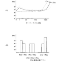
光ディスク記録装置は、メーカーや型式によって書換型光ディスクに照射するレーザ光の記録パワー、消去パワー、ボトムパワーなどの設定が異なるため、以下のような記録特性を示す。図1は、書換型光ディスクのオーバーライト回数とジッタとの関係、及び異なる記録パワーで光ディスクにオーバーライトを行った時のジッタの変化を示したグラフである。なお、図1には、同じ型式の書換型光ディスクに対して、異なる記録パワーで連続してオーバーライトした場合を示している。また、記録パワーの大きさはP2w<P0w<P1wで、P0wが最適記録パワーである。
【0007】
(1)書換型光ディスクは、照射されるレーザ光の記録パワーに応じて、再生時のジッタ及びオーバーライトの実行可能回数が異なる値となる。すなわち、図1(A)に示すように、書換型光ディスクに対して最適記録パワーP0wで記録した場合、1回目でジッタが悪化するが、オーバーライトの回数が増えるに連れてジッタが徐々に改善する。そして、10回程度オーバーライトを行うと、それ以降はジッタが安定し、1000回を超えると急激にジッタが悪化する。したがって、ユーザは、書換型光ディスクに対して最適記録パワーP0wで記録した場合、Orange Book Part3に規定された書換可能回数である1000回はオーバー ライトを行うことができる。
【0008】
また、書換型光ディスクに対して最適記録パワーP0wよりも強い記録パワーP1wで記録した場合、オーバーライト回数が少ない時でもジッタが悪化せず安定しており、また、最適記録パワーP0wの時よりも常にジッタが良い。しかしながら、光ディスクの劣化が早く、1000回よりも少ないオーバーライト回数で急激にジッタが悪化する。したがって、ユーザは、書換型光ディスクに対して記録パワーP1wで記録した場合、書換型光ディスクの寿命が短くなってしまうため、1000回よりも大幅に少ない回数しかオーバーライトを行うことができない。
【0009】
一方、書換型光ディスクに対して最適記録パワーP0wよりも弱い記録パワーP2wで記録した場合、最適記録パワーP0wの場合と同様の特性を示すが、ジッタの値は最適記録パワーP0wの時よりも常に悪い値となる。また、光ディスクの劣化が遅く、オーバーライトを1000回以上行うとジッタが悪化する。したがって、ユーザは、書換型光ディスクに対して記録パワーP2wで記録した場合、書換型光ディスクの寿命が長くなるため、1000回よりも多くオーバーライトを行うことができる。
【0010】
(2)書換型光ディスクは、ある記録パワーでデータを記録後に、異なる記録パワーでオーバーライトすると、ジッタが変化する。すなわち、光ディスクに照射するレーザ光の記録パワーがP2w<P0w<P1wの関係である場合、図1(B)に示すように、書換型光ディスクに対して記録パワーP2wで記録後に、記録パワーP0w(>P2w)でオーバーライトすると、ジッタが良くなる。また、書換型光ディスクに対して記録パワーP0wで記録後に、同じ記録パワーP0wでオーバーライトすると、ジッタは変化しない。一方、書換型光ディスクに対して記録パワーP1wで記録後に記録パワーP0w(<P1w)でオーバーライトすると、ジッタが悪くなる。
【0011】
(3)書換型光ディスクは、照射されるレーザ光のスポット形状が同じ場合、形成されるピットの幅は記録パワーを強くすると広くなる。図2は、書換型光ディスクに形成されるピットの形状を示した図である。例えば、光ディスクに照射するレーザ光の記録パワーの関係がP2w<P0w<P1wである場合、図2に示すように、記録パワーが大きくなるのに従って、ピットの幅が大きくなり、各ピットの幅はW2<W0<W1の関係となる。また、光ディスクに照射するレーザ光の消去パワーの関係がP2e<P0e<P1eである場合、消去パワーが大きくなるのに従って、消去範囲が広くなる。
【0012】
図2に示した例では、記録パワーP2wのレーザ光を照射して形成したピットは、レーザ光の消去パワーがP2e以上であれば完全に消去できる。つまり、消去パワーがP2e,P0e,P1eで消去できる。また、記録パワーP0wのレーザ光を照射して形成したピットは、レーザ光の消去パワーがP0e以上であれば完全に消去できる。つまり、消去パワーがP0e,P1eで完全に消去できるが、消去パワーがP2eでは完全には消去できず端部が残ってしまう。さらに、記録パワーP1wのレーザ光を照射して形成したピットは、レーザ光の消去パワーがP1e以上であれば完全に消去できる。つまり、消去パワーがP1eで完全に消去できるが、消去パワーがP2e,P0eでは完全には消去できず、端部が残ってしまう。
【0013】
したがって、旧データを記録した光ディスク記録装置と異なる光ディスク記録装置で書換型光ディスクにオーバーライトすると、以下のような現象が発生する。図3は、書換型光ディスクにオーバーライトする際のイメージ図である。すなわち、図3(A)に示すように、書換型光ディスクに対して、記録パワーP2wで記録後に消去パワーP0e、記録パワーP0w(>P2w)のレーザ光を照射してオーバーライトした場合、記録パワーP2wのレーザ光を照射して形成した元のピットは、照射パワーP0eのレーザ光によって完全に消去されるので、記録パワーP2wで形成したピットが残らない。また、記録パワーP0wのレーザ光を照射してピットを形成すると、図1(B)に示したように記録パワーP0wのレーザ光を照射した方がジッタが良いので、ジッタが改善されてエラーレートが低くなる。
【0014】
一方、図3(B)に示すように、書換型光ディスクに対して、記録パワーP1wで記録後に消去パワーP0e、記録パワーP0w(<P1w)のレーザ光を照射してオーバーライトした場合、記録パワーP1wレーザ光を照射して形成した元のピットは、消去パワーP0eのレーザ光を照射しても消去範囲が狭いために完全に消去されずに端部が残ってしまう。また、記録パワーP0wのレーザ光を照射して形成したピットは、記録パワーP1wのレーザ光を照射して形成したピットよりも幅が狭いため、元のピットの端部と新しく形成したピットとが重なる部分ができる。そのため、ジッタが悪くなりエラーレートが高くなる。
【0015】
また、光ディスク記録装置では、メーカーや型式によってライトストラテジの設定が異なっている。図4は、書換型光ディスク用のライトストラテジの一例である。さらに、一般的に書換型光ディスクのレーザパワーの制御は、ライトストラテジを設定して行うが、ファームウェアのバージョンを変更した際に、記録パワーPw、消去パワーPe、及びボトムパワーPbが同時に変更されたり、これらのいずれかが変更されたりする。このように、記録パワーPw、消去パワーPe、またはボトムパワーPbの少なくともいずれかが変更されると、同じ光ディスク記録装置であっても、前に記録したデータを完全に消去できずにピットの端部が残って、ジッタが悪くなりエラーレートが高くなる。
【0016】
光ディスク記録装置が光ディスクに照射するレーザ光のスポット形状は、光ディスク記録装置のメーカーによって異なっている。図5は、光ディスク記録装置のレーザ光のスポット形状及び書換型光ディスクに形成されるピットの形状を示した図である。図5に示すように、書換型光ディスクがCD−RWの場合、光ディスク記録装置のスポット形状は、スポット進行方向に対してA社製が横長の楕円形、B社製が縦長の楕円形、C社製が斜め方向に長い楕円形である。また、書換型光ディスクがDVD−RW、DVD+RW、DVD−RAMの場合、光ディスク記録装置のスポット形状は、円形、縦長楕円、横長楕円、斜め方向に長い楕円が存在する。
【0017】
このようにレーザ光のスポット形状が異なっているため、書換型光ディスクに形成されるピットの形状(幅)は、図5に示したように、光ディスクの記録装置のメーカーによって異なったものとなる。そのため、あるメーカーの光ディスク記録装置でデータを記録した書換型光ディスクに、別のメーカーの光ディスク記録装置でデータをオーバーライトした場合、記録パワーや消去パワーが同じ値に設定されていたとしても、図3(B)に基づいて説明した現象と同様の現象が発生する。すなわち、図5(A)に示したスポット形状のレーザ光を照射して書換型光ディスクDにデータを記録後に、図5(B)に示したスポット形状のレーザ光を照射してデータのオーバーライトした場合には、元のピットの端部が消去されずに残るため、ジッタが悪くなりエラーレートが高くなる。一方、図5(B)に示したスポット形状のレーザ光を照射して書換型光ディスクDにデータを記録後に、図5(A)に示したスポット形状のレーザ光を照射してデータのオーバーライトした場合には、元のピットが完全に消去されるので、ジッタが良くなり、エラーレートが低くなる。
【0018】
また、光ディスク記録装置では、一般的に、記録速度を変更した場合でも、同じ幅(形状)のピットが形成され、オーバーライトする場合には、旧データが完全に消去できるように記録パワーや消去パワーが設定されている。しかしながら、レーザダイオードや書換型光ディスクの材料のばらつきなどにより、記録速度が異なると、形成されるピットの幅(形状)が異なり、オーバーライトする場合には、以前に形成したピットを完全に消去できない場合がある。例えば、4倍速で記録した書換型光ディスクに1倍速でオーバーライトすると、4倍速で記録したピットを完全に消去できないために、ジッタが悪くなってエラーレートが高くなる場合がある。
【0019】
以上のように、従来の光ディスク記録装置では、メーカー、型式、ファームウェアのバージョン、記録速度などによって書換型光ディスクに照射するレーザ光の記録パワー、消去パワー、ボトムパワー、ライトストラテジ、スポット形状などの記録条件が異なっていた。また、書換型光ディスクは、記録条件に応じて記録特性が異なっていた。そのため、ある光ディスク記録装置でデータを記録した書換型光ディスクに対して、別の光ディスク記録装置でオーバーライトすると、書換型光ディスクに形成されたピットを完全に消去したり、新たなピットで元のピットを覆うように形成することができないために、ジッタが悪くなりエラーレートが高くなっていた。
【0020】
そこで、本発明は、ある光ディスク記録装置で記録した書換型光ディスクを別の光ディスク記録装置でオーバーライトしても、ジッタが悪化せずエラーレートの低いデータを得られる光ディスク記録方法及び光ディスク記録装置を提供することを目的とする。
【0021】
【課題を解決するための手段】
この発明は、上記の課題を解決するための手段として、以下の構成を備えている。
【0024】
(1)書換型光ディスクのプログラム領域に記録されている旧データ上に新データを上書きする時に、この旧データの再生信号からクロストーク量を検出し、
前記書換型光ディスクの試し書き領域で試し書きを行って最適記録パワーを決定し、この最適記録パワーで記録したデータの再生信号から検出したクロストーク量である基準クロストーク量と、前記検出したクロストーク量との差に基づいて記録条件を設定し、この記録条件を適用して新データを上書きすることを特徴とする。
【0025】
クロストーク量は、書換型光ディスクに照射する記録パワーが高くなり、ピットの幅が太くなるほど大きくなるという特性があるので、クロストーク量を比較することで、旧データの記録パワー値を推測することが可能である。この構成においては、書換型光ディスクに試し書きを行って最適記録パワーを決定し、この最適記録パワーで記録したテストデータの再生を行う。そして、再生信号からクロストーク量の値を求め、この値を基準クロストーク量とする。また、書換型光ディスクに記録されたデータの再生信号から検出したクロストーク量と、基準クロストーク量と、の差を求めることで、基準の記録パワー(最適記録パワー)に対して旧データをどのくらいのパワーで記録したかを把握する。そして、消去パワーや記録パワーの条件を設定して、データを上書きする。したがって、書換型光ディスクに記録された旧データを完全に消去して新データを記録することが可能となり、新データのジッタの悪化を防止してエラーレートを低くすることができる。また、新しく発売された書換型光ディスクであっても、その書換型光ディスクに最適な記録条件を、ファームウェアなどの更新を行うことなく速やかに決定することができる。
【0034】
(2)書換型光ディスクに記録されている旧データ上に新データを上書きする時に、前記書換型光ディスクの試し書き領域へ照射するレーザパワーを所定量ずつ変化させながら試し書きを行い、この試し書きを行ったデータの再生信号から最適記録パワーを決定し、この最適記録パワーによって記録されたデータの再生信号のピーク値とボトム値とから第1の再生信号のピークトゥピーク値を取得し、
前記旧データを再生した再生信号のピーク値とボトム値とから第2の再生信号のピークトゥピーク値を取得し、
前記第1の再生信号のピークトゥピーク値と前記第2の再生信号のピークトゥピーク値との差に応じて、前記書換型光ディスクへ照射するレーザ光の消去パワーを補正し、この補正した消去パワーを適用して新データを上書きすることを特徴とする。
【0035】
書換型光ディスクに記録された旧データの再生信号のピークトゥピーク値と、最適記録パワーで記録したデータの再生信号のピークトゥピーク値と、の差を求めることで、旧データと上書きするデータとの記録条件の差を求めることができる。したがって、この差に応じて消去パワーを補正することで、旧データを完全に消去して、最適な記録条件で上書きするデータを記録することができる。
【0036】
(3)書換型光ディスクに記録されたデータを再生する再生手段と、
前記再生手段の再生信号からクロストーク量を検出するクロストーク検出手段と、
前記クロストーク検出手段が検出したクロストーク量に基づいて記録条件を設定する記録条件設定手段と、
前記記録条件設定手段によって設定された記録条件を適用して旧データ上に新データを上書きする記録手段と、
書換型光ディスクのプログラム領域に記録されている旧データ上に新データを上書きする時に、前記クロストーク検出手段に、この旧データの再生信号からクロストーク量を検出させ、
前記記録手段に前記書換型光ディスクの試し書き領域に試し書きを行わせて最適記録パワーを決定し、この最適記録パワーで記録したデータの再生信号から検出したクロストーク量である基準クロストーク量と、前記検出したクロストーク量との差に基づいて記録条件を設定し、この記録条件を適用して前記記録手段に新データを上書きさせる制御手段と、
を備えたことを特徴とする。
【0037】
この構成においては、(1)と同様の効果を得ることができる。
【0038】
(4)書換型光ディスクに記録されたデータを再生する再生手段と、
前記書換型光ディスクに記録されている旧データ上に新データを上書きする時に、前記書換型光ディスクの試し書き領域へ照射するレーザパワーを所定量ずつ変化させながら試し書きを行い、この試し書きを行ったデータの前記再生手段の再生信号から最適記録パワーを決定し、この最適記録パワーによって記録されたデータの再生信号のピーク値とボトム値とから第1の再生信号のピークトゥピーク値を取得し、また、前記旧データを再生した再生信号のピーク値とボトム値とから第2の再生信号のピークトゥピーク値を取得するエンベロープ検出手段と、
前記エンベロープ検出手段が取得した前記第1の再生信号のピークトゥピーク値と前記第2の再生信号のピークトゥピーク値との差に応じて、前記書換型光ディスクへ照射するレーザ光の消去パワーを補正する記録条件設定手段と、
前記記録条件設定手段によって補正された消去パワーを適用して旧データ上に新データを上書きする記録手段と、
を備えたことを特徴とする。
【0039】
この構成においては、(2)と同様の効果を得ることができる。
【0040】
【発明の実施の形態】
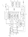
以下の説明では、書換型光ディスクの一例としてCD−RWにデータをオーバーライトする場合について説明する。まず、本発明の実施形態に係る光ディスク記録装置の詳細について説明する。図6は、本発明の実施形態に係る光ディスク記録装置の構成を示したブロック図である。本実施形態では、光ディスクに照射する光ビームとしてレーザ光を用いる構成を示す。図6に示すように、光ディスク記録装置1は、光ピックアップ10、スピンドルモータ11、RFアンプ12、サーボ回路13、ATIP検出回路14、デコーダ15、制御部16、エンコーダ17、ストラテジ回路18、レーザドライバ19、レーザパワー制御回路20、周波数発生器21、クロストーク検出回路22、エンベロープ検出回路23、再生信号品位検出回路部24、記憶部25、操作部27、及び表示部28を備えている。また、光ピックアップ10、サーボ回路13、エンコーダ17、ストラテジ回路18、レーザドライバ19及びレーザパワー制御回路20によって、データの記録手段である記録部29が構成されている。さらに、光ピックアップ10及びRFアンプ12によって、データの再生手段である再生部30が構成されている。
【0041】
スピンドルモータ11は、データの記録対象である光ディスクDを回転駆動するモータである。また、スピンドルモータの回転軸先端部には、光ディスクを保持(チャッキング)するためのターンテーブルなどからなる図外の光ディスク保持機構が設けられている。
【0042】
光ピックアップ10は、レーザダイオード、レンズ及びミラーなどの光学系、戻り光(反射光)受光素子、並びにフォーカスサーボ機構などを備えている。また、記録及び再生時にはレーザ光を光ディスクDに対して照射して、光ディスクDからの戻り光を受光して受光信号であるEFM(Eight to Fourteen Modulation)変調されたRF信号をRFアンプ12に出力する。なお、フォーカスサーボ機構は、光ピックアップ10のレンズと光ディスクのデータ面との距離を一定に保つためのサーボ機構である。また、光ピックアップ10は、モニタダイオードを備えており、光ディスクDの戻り光によってモニタダイオードに電流が生じ、この電流がレーザパワー制御回路20へ供給されるようになっている。
【0043】
周波数発生器21は、スピンドルモータ11が出力した回転角度や回転数を検出して、その信号をサーボ回路13に出力する。
【0044】
RFアンプ12は、光ピックアップ10から供給されるEFM変調されたRF信号を増幅して、増幅後のRF信号をサーボ回路13、ATIP検出回路14、クロストーク検出回路22、エンベロープ検出回路23、再生信号品位を測定する再生信号品位検出回路部24、及びデコーダ15に出力する。
【0045】
デコーダ15は、再生時には、RFアンプ12から供給されるEFM変調されたRF信号をEFM復調して再生データを生成し、記憶部25に出力する。また、デコーダ15は、記録時には、テスト記録によって記録された領域を再生する際に、RFアンプ12から供給されたRF信号をEFM復調する。
【0046】
本実施形態に係る光ディスク記録装置1では、データを記録する際に、本データの記録に先立ち、光ディスクDの内周側のPCA(Power Calibration Area )領域にテスト記録を行う。そして、このテスト記録した領域の再生結果に基づいて、光ディスクDに対して良好な記録を行える記録条件を求めるように構成されている。
【0047】
ここで、光ディスクDのテスト記録を行う領域について、図7を用いて説明する。図7は、光ディスクの領域構成を示した断面図である。光ディスクDの外径は120mmであり、光ディスクDの直径46〜50mmの区間がリードイン領域114として用意され、その外周側にデータを記録するプログラム領域118及び残余領域120が用意されている。一方、リードイン領域114よりも内周側には、内周側PCA領域112が用意されている。また、内周側PCA領域112には、テスト領域112aと、カウント領域112bと、が用意されている。このテスト領域112aには、前述のように本記録に先立ち、テスト記録が実施される。ここで、テスト領域112aとしては、テスト記録を複数回行える領域が用意されている。また、カウント領域112bには、テスト記録終了時にテスト領域112aのどの部分まで記録が終了しているかを示すEFM信号が記録される。したがって、次にこの光ディスクDに対してテスト記録を行う際には、カウント領域112bのEFM信号を検出することにより、テスト領域112aのどの位置からテスト記録を開始すれば良いかが、わかるようになっている。本実施形態に係る光ディスク記録装置1では、データの本記録を行う前に上記のテスト領域112aへテスト記録を行っている。
【0048】
図6に戻り、記憶部25は、デコーダ15から出力された光ディスクDの再生データや、光ディスク記録装置1の外部から入力されたデータなどを一旦記憶する。そして、再生時には記憶したデータを図外のデータ再生部へ出力し、記録用光ディスクにデータを記録する時には、記憶したデータをエンコーダ17へ出力する。
【0049】
ATIP検出回路14は、RFアンプ12から供給されたRF信号中に含まれるウォブル信号成分を抽出し、このウォブル信号成分に含まれる各位置の時間情報(アドレス情報)、及び光ディスクを識別する識別情報(ディスクID)やディスクに使われている色素などのディスクの種類を示す情報を復号し、制御部16に出力する。ここで、ウォブル信号成分とは、記録用光ディスクの蛇行した記録トラックの蛇行周波数を表す信号成分であり、時間情報や識別情報などは蛇行周波数をFM変調することで記録されている。
【0050】
クロストーク検出回路22は、光ディスクに記録されたデータを再生して、隣接トラックの信号量(クロストーク量)を検出する。このクロストーク量は、トラックピッチやピットの幅(形状)によって変化する。
【0051】
エンベロープ検出回路23は、光ディスクDへテスト記録を行う前に、光ディスクDのテスト領域112aのどの部分からテスト記録を開始するかを検出するために、上述した光ディスクDのカウント領域112bでのEFM信号のエンベロープを検出する。
【0052】
再生信号品位検出回路部24は、光ディスクDのテスト記録領域を再生している時に、RFアンプ12から供給されるRF信号から再生信号品位に関係するβ値やアシンメトリを算出し、算出結果を制御部16に出力する。ここで、β値は、EFM変調された信号波形のピークレベル(符号は+)をa、ボトムレベル (符号は−)をbとすると、β=(a+b)/(a−b)で求めることができる。
【0053】
サーボ回路13は、スピンドルモータ11の回転制御、並びに光ピックアップ10のフォーカス制御、トラッキング制御、及び送り制御を行う。本実施形態に係る光ディスク記録装置1では記録時には、光ディスクDを角速度一定で駆動する方式であるCAV(Constant Angular Velocity)方式と、光ディスクDを線 速度一定にして駆動する方式であるCLV(Constant Linear Velocity)方式と、を切り替えることができるようになっている。そのため、サーボ回路13は、制御部16から供給される制御信号に応じてCAV方式とCLV方式とを切り替える。ここで、サーボ回路13によるCAV制御では、周波数発生器21によって検出されるスピンドルモータ11の回転数が、設定した回転数と一致するように制御される。また、サーボ回路13によるCLV制御では、RFアンプ12から供給されるRF信号中のウォブル信号が設定された速度倍率になるように、スピンドルモータ11が制御される。
【0054】
エンコーダ17は、記憶部25から供給される記録データをEFM変調し、ストラテジ回路18に出力する。ストラテジ回路18は、エンコーダ17から供給されたEFM信号に対して時間軸補正処理などを行い、レーザドライバ19に出力する。レーザドライバ19は、ストラテジ回路18から供給される記録データに応じて変調された信号と、レーザパワー制御回路20の制御に従って光ピックアップ10のレーザダイオードを駆動する。
【0055】
レーザパワー制御回路20は、光ピックアップ10のレーザダイオードから照射されるレーザパワーを制御する。具体的には、レーザパワー制御回路20は、光ピックアップ10のモニタダイオードから供給される電流値と、制御部16から供給される最適なレーザパワーの目標値を示す情報と、に基づいて、最適なレーザパワーのレーザ光が光ピックアップ10から照射されるように、レーザドライバ19を制御する。
【0056】
制御部16は、CPU、ROM、及びRAM等から構成されており、ROMに格納されたプログラムに従って光ディスク記録装置1の各部を制御する。また、制御部16は、上述したようにデータの本記録に先立ち、光ディスク記録装置1にセットされた光ディスクDの所定の領域に対し、テスト記録を行うように装置の各部を制御する。そして、制御部16では、上述したテスト記録された領域を再生している際に得られる信号から、再生信号品位検出回路部24によって検出されたβ値などの再生信号品位に基づいて、光ディスク記録装置1がテスト記録を行った光ディスクDに対して、再生信号品位と、目標βやライトストラテジなどの装置記録パラメータ(記録条件)との関係を求めることにより、記録エラーのない良好な記録を行うことができる記録可能速度を求める記録速度判定処理などを行う。
【0057】
記憶部25は、書換型光ディスクの型番毎に基準クロストーク量CT0を記憶している。操作部27は、光ディスクにデータを記録する操作を行うためのものである。表示部28は、操作部27で行った操作内容などユーザに伝達したい内容を、表示するためのものである。
【0058】
[第1実施形態]
次に、本発明の第1実施形態に係る光ディスク記録装置について説明する。図8は、記録領域と再生スポットとの関係を示した模式図であり、(A)が最適記録パワーで記録された領域と再生スポットとの関係を示し、(B)が最適記録パワーよりもハイパワーで記録された領域と再生スポットとの関係を示す。図8 (A)に示すように、最適記録パワーでデータを記録すると、ピット(書換型光ディスクにレーザ光を照射して記録層をアモルファス状態にした部分)の幅が適正であるため、スポットがランド上に位置する時にピットから受ける影響は小さいので反射光の信号レベル低下は少ない。また、このように最適記録パワーでデータを記録した場合、あるトラックを再生中に他のトラックからの影響(クロストーク量)はほとんどない。一方、図8(B)に示すように、最適記録パワーよりもハイパワーでデータを記録するとピットの幅が太くなるため、スポットがランド上に位置する時にピットからより多くの影響を受けるため反射光の信号レベルがより低下してしまう。このように、書換型光ディスクは、記録パワーに応じてピットの幅が異なり、それに応じてクロストーク量が異なる。
【0059】
そこで、本発明の第1実施形態に係る光ディスク記録装置は、書換型光ディスクの最適記録パワー時のクロストーク量を記憶しておき、書換型光ディスクにデータをオーバーライトする際に、この書換型光ディスクに記録されたデータを再生して、再生信号中のクロストーク量を検出して、このクロストーク量と基準クロストーク量とを比較する。クロストーク量は、上記のように、ピットの幅が太くなるほど、つまり記録パワーが高いほど大きくなるという特性があるので、クロストーク量を比較することで、記録パワー値を検出することが可能である。本発明の第1実施形態に係る光ディスク記録装置では、この特性を利用して、両データのクロストーク量を比較して、この比較結果に応じて消去パワーや記録パワーなどの記録条件を変更して(例えば、旧データを記録した光ディスク記録装置と同様の記録条件に変更して)オーバーライトする。これにより、旧データを記録した光ディスク記録装置と異なる光ディスク記録装置でデータのオーバーライトする際に、旧データを完全に消去できるので、ジッタの悪化を防止してエラーレートを低くすることができる。
【0060】
クロストーク量の比較結果に応じて変更する記録条件としては、書換型光ディスクにオーバーライトする際に、上書きする旧データが確実に消去できるように、光ディスク記録装置が書換型光ディスクに照射するレーザ光の消去パワーを変更すると良い。また、記録パワー、ボトムパワー(バイアスパワー)、ε(消去パワー/記録パワー)、ライトストラテジ、OPCで得た記録パワーの補正値などの条件を変更して、元の光ディスク記録装置と同様にデータをオーバーライト(消去及び記録)できるようにしても良い。
【0061】
但し、旧データを記録した光ディスク記録装置の記録パワーの方が、オーバーライトする光ディスク記録装置の記録パワーよりも弱い場合などでは、消去パワー及び記録パワーを大きくしなければならないため、書換型光ディスクや光ディスク記録装置1のレーザダイオードの劣化が早まってしまう。そこで、このような場合は、書換型光ディスクにオーバーライトする際に、書換型光ディスクに照射するレーザ光の消去パワーを旧データのクロストーク量に応じて強くするとともに、記録パワーは変更せずに光ディスク記録装置に自己の初期値として設定された値を用いてデータをオーバーライトするように設定すると良い。これにより、書換型光ディスクや光ディスク記録装置1のレーザダイオードの劣化を抑制することができる。
【0062】
また、旧データを記録した光ディスク記録装置の記録パワーよりも、オーバーライトする光ディスク記録装置の記録パワーの方が強い場合などでは、消去パワー及び記録パワーを変更せずに初期設定値のまま上書きすれば良い。
【0063】
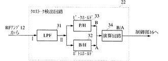
図9は、クロストーク検出回路の詳細を示したブロック図である。図10は、光ピックアップを移動させた際に出力される信号と、クロストーク量の定義を示した波形図である。光ディスク記録装置1では、前記のようにクロストーク検出回路22でクロストーク量を検出する。図9に示すように、クロストーク検出回路22は、ローパスフィルタ(LPF)31、ボトムホールド回路(B/H)32、ピークホールド回路(P/H)33、及び演算回路34から成る。
【0064】
ローパスフィルタ31は、RFアンプから出力された信号中の高周波成分をカットして低周波成分をボトムホールド回路32及びピークホールド回路33へ出力する。ボトムホールド回路32は、ローパスフィルタ31から出力された信号のボトム値Aをホールドして出力する。ピークホールド回路33は、ローパスフィルタ31から出力された信号のピーク値Bをホールドして出力する。演算回路34は、ボトムホールド回路32から出力されたボトム値A及びピークホールド回路33から出力されたピーク値Bを用いて演算を行いクロストーク量を求める。
【0065】
クロストーク検出回路22では、以下のような処理が行われる。光ディスクを回転させながら光ピックアップを移動させると、図10(A)に示すように、RFアンプ12から信号Iが出力される。信号Iは、ミラーレベルに対して反射率の低いピット部分でレベルの下がる信号である。ピット信号(EFM)は、高周波数信号である。また、ピット信号のボトムレベルは、ランドとグルーブの繰り返し周期によっても増減があり、そのエンベロープ信号には所定周期のレベル増減が見られる。図10(A)において実線で示したエンベロープは、最適記録パワーで記録された部分を再生した場合のエンベロープであり、図10(A)において、波線で示したエンベロープは高パワーで記録された部分を再生した場合のエンベロープである。
【0066】
RFアンプ12から出力された信号Iは、ローパスフィルタ31を通過すると図に示した信号IIとなる。信号IIは、信号Iの下側エンベロープ信号であり、グルーブにおいて最下端レベルとなり、ランドにおいて上端レベルとなる。ボトムホールド回路32は、ローパスフィルタ31から出力された信号IIの最下端レベルをAレベルとしボトムホールド行って取得する。また、ピークホールド回路33は、ローパスフィルタ31から出力された信号IIの上端レベルをBレベルとしてピークホールド行って取得する。演算回路34は、ボトムホールド回路32から出力されたボトム値A及びピークホールド回路33から出力されたピーク値Bを用いて除算B/Aを行うことでクロストークレベルを算出する。
【0067】
光ディスク記録装置1では、書換型光ディスクにオーバーライトする場合、以下のような処理を行う。図11は、第1実施形態に係る光ディスク記録装置のクロストーク量の検出動作を説明するためのフローチャートである。
【0068】
ユーザは、CD−RWにデータを記録する場合、まず、光ディスク記録装置1のディスクトレイにCD−RWをセットする。光ディスク記録装置1の制御部16は、CD−RWがセットされたことを検出すると(s1)、CD−RWをチャキングした後、所定の場所まで光ピックアップを移動し、レーザ光を照射して初期情報を取得する(s2)。具体的には、まず、制御部16は、光ディスクの種類を識別するためにレーザ光の反射率を判定する。この時、光ディスクの反射率が低くければ書換型の光ディスク(CD−RW)であり、反射率が高ければ追記型の光ディスク(CD−R)または読出型(非記録型)の光ディスク(CD−ROM)であると判定できる。また、制御部16は、光ディスク記録装置1にセットされた光ディスクのリードインエリアにおけるウォブル成分の有無を検出し、ウォブル情報があった場合にはATIP情報を検出する。ATIP情報を検出できた場合は、書換型または追記型の光ディスクと判定し、ATIP情報に含まれるディスクID(メーカーコード)やSTLI(Start Time of Lead-In Area: メーカーコード及びディスクコードに相当)などの情報を各種の制御に利用する。このように、制御部16は、反射率とATIP情報とによって、書換型、追記型、及び読出型のいずれの光ディスクであるかを判定する。また、ATIP情報によって光ディスクのディスクIDを取得する。
【0069】
続いて、制御部16は、ユーザがセットしたCD−RWに対して行う処理を問い合わせる内容を表示部28に表示する(s3)。ユーザは、この表示に応じて、セットしたCD−RWに対して実行させたい処理を入力する。制御部16は、操作部27からの入力を検出すると(s4)、データの再生が設定された場合(s5)、データの再生処理を行う(s6)。制御部16は、データの再生が完了すると処理を終了する。
【0070】
一方、制御部16は、データの記録が設定された場合(s5)、記録動作が初期記録であるか上書きであるかを判定する(s7)。具体的には、リードインエリア及びPMAにおけるEFM信号の有無を判定し、双方またはリードインエリアにEFM信号が記録されていない場合は初期記録と判定する。制御部16は、CD−RWがブランクディスクまたは記録途中である場合、光ディスクDのデータを未記録の領域に初めてデータを記録するので、PCAでOPCを行って最適記録パワーを決定する(s8)。そして、制御部16は、CD−RWにデータを記録または追記して(s9)、処理を終了する。
【0071】
一方、制御部16は、ステップs7において、CD−RWのリードインエリア及びPMAにEFM信号が記録されている場合、上書きを行うと判定して、この書換型光ディスクに記録された旧データを再生する(s11)。制御部16は、クロストーク検出回路22から書換型光ディスクに記録されたデータのクロストーク量CT1を取得すると(s12)、記憶部25から基準クロストーク量CT0を読み出す(s13)。続いて、CT1−CT0の演算を行い(s14)、演算結果が0を越える場合(s15)、記録条件を変更する。例えば、基準消去パワーP0e及び基準記録パワーP0wにCT1/CT0と所定の計数を掛け合わせて補正を行い、これらの補正値を設定する(s16)。そして、制御部16は、これらの補正した消去パワー及び補正した記録パワーで書換型光ディスクにデータをオーバーライトし(s18)、データの記録が完了したら、処理を終了する。
【0072】
一方、制御部16は、CT1−CT0の演算結果が0以下である場合(s15)、記録条件を光ディスク記録装置1に設定された初期値に設定する。すなわち、基準消去パワーP0e及び基準記録パワーP0wに設定して(s17)、書換型光ディスクにオーバーライトし(s18)、データの記録が完了したら、処理を終了する。
【0073】
ここで、基準クロストーク量CT0は、上記のように記憶部25に書換型光ディスクの型番毎に記録しておいても良いが、以下のようにして基準クロストーク量CT0を求めることもできる。すなわち、光ディスク記録装置でデータをオーバーライトする際に、OPCを行って最適記録パワーを決定して、この最適記録パワーで記録したテストデータの再生を行って、クロストーク量の値を求め、この値を基準クロストーク量CT0とする。そして、前記のように、書換型光ディスクに記録されていた旧データを再生してこのデータのクロストーク量CT1を求めて、CT1−CT0の差に応じて記録条件を決定するようにすればよい。このようにすることで、記録条件を決定する時間は多少増加するが、新しく発売された書換型光ディスクであっても、その書換型光ディスクに最適な記録条件を、ファームウェアなどの更新を行うことなく速やかに決定することができる。
【0074】
[第2実施形態]
次に、本発明の第2実施形態に係る光ディスク記録装置について説明する。図12は、異なる記録パワーで記録したピット、及び各ピットの再生波形を示した図である。図12(A)において、ピットaは、最適な記録パワーよりも高い記録パワーで、かつ最適なストラテジよりも短いストラテジで記録したピットである。ピットbは、最適な記録パワーで、かつ最適なストラテジで記録したピットである。ピットcは、最適な記録パワーよりも低い記録パワーで、かつ最適なストラテジよりも長いストラテジで記録したピットである。図12(A)に示すように、ピットa、ピットb、及びピットcの幅の関係は、Wa>Wb>Wcであり、ピットa、ピットb、及びピットcの長さの関係は、La<Lb<Lcである。また、図12(B)に示すように、各ピットを再生した場合、再生光スポットとの大きさの関係から、得られる再生信号は、ピットの幅が太いほど振幅のピークトゥピーク値(以下、PP値と称する。)が大きくなる。しかしながら、図12 (C)に示すように、各再生信号を2値化した場合、すべて同じ信号となる。
【0075】
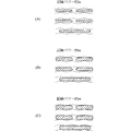
図13は、図12(A)に示した条件で記録した3T〜11Tのピットを再生した再生信号パターンである。以下、この再生信号パターンをeyeパターンと称する。図13において、(A)は、最適な記録パワーよりも高い記録パワーで、かつ最適なストラテジよりも短いストラテジで記録したピットの再生信号のeyeパターンである。(B)は、最適な記録パワーで、かつ最適なストラテジで記録したピットの再生信号のeyeパターンである。(C)は、最適な記録パワーよりも低い記録パワーで、かつ最適なストラテジよりも長いストラテジで記録したピットの再生信号のeyeパターンである。図13に示すように、中心波線でスライスされたときの信号はどの条件も同じであるが、eyeパターンの開度であるPP値は、記録パワーが大きくなるほど大きくなることがわかる。すなわち、図13に示した各eyeパターンのPP値の関係は、PPa>PPb>PPcとなる。
【0076】
そこで、本発明の第2実施形態に係る光ディスク記録装置は、書換型光ディスクにデータをオーバーライトする際に、書換型光ディスクに対してOPCを行って最適記録パワーを求め、最適記録パワーで記録したデータのPP値を算出する。また、この書換型光ディスクに記録された上書きする旧データを再生して、PP値を検出して、このPP値と、最適記録パワーで記録したデータのPP値と、を比較する。PP値は、上記のように、記録パワーが高いほど大きくなるという特性があるので、PP値を比較することで、記録パワー値を検出することが可能である。本発明の第2実施形態に係る光ディスク記録装置では、この特性を利用して、両データのPP値(eyeパターンの開度)を比較して、その比較結果に応じて消去パワーや記録パワーなどの記録条件を変更して(例えば、旧データを記録した光ディスク記録装置と同様の記録条件に変更して)オーバーライトする。これにより、旧データを記録した光ディスク記録装置と異なる光ディスク記録装置でデータのオーバーライトする際に、旧データを完全に消去できるので、ジッタの悪化を防止してエラーレートを低くすることができる。
【0077】
PP値の比較結果に応じて変更する記録条件としては、書換型光ディスクにオーバーライトする際に、上書きする旧データが確実に消去できるように、光ディスク記録装置が書換型光ディスクに照射するレーザ光の消去パワーを変更すると良い。また、記録パワー、ボトムパワー(バイアスパワー)、ε(消去パワー/記録パワー)、ライトストラテジ、OPCで得た記録パワーの補正値などの条件を変更して、元の光ディスク記録装置と同様にデータをオーバーライト(消去及び記録)できるようにしても良い。
【0078】
但し、旧データを記録した光ディスク記録装置の記録パワーの方が、オーバーライトする光ディスク記録装置の記録パワーよりも弱い場合などでは、消去パワー及び記録パワーを大きくしなければならないため、書換型光ディスクや光ディスク記録装置1のレーザダイオードの劣化が早まってしまう。そこで、このような場合は、書換型光ディスクにオーバーライトする際に、書換型光ディスクに照射するレーザ光の消去パワーを旧データのPP値に応じて強くするとともに、記録パワーは変更せずに光ディスク記録装置に自己の初期値として設定された値を用いてデータをオーバーライトするように設定すると良い。これにより、書換型光ディスクや光ディスク記録装置1のレーザダイオードの劣化を抑制することができる。
【0079】
図14は、エンベロープ検出回路の詳細を示したブロック図である。光ディスク記録装置1では、エンベロープ検出回路23で再生信号のPP値を検出する。図14に示すように、エンベロープ検出回路23は、ACカプラ41、ボトムホールド回路(B/H)42、ピークホールド回路(P/H)43、及び演算回路(オペアンプ)44から成る。
【0080】
ACカプラ41は、RFアンプ12から出力された信号中の直流成分をカットして交流成分をボトムホールド回路42及びピークホールド回路43へ出力する。ボトムホールド回路42は、ACカプラ41から出力された信号のボトム値 (ローレベル側のピーク値)Aをホールドして出力する。ピークホールド回路33は、ACカプラ41から出力された信号のピーク値(ハイレベル側のピーク値)Bをホールドして出力する。演算回路44は、ボトムホールド回路32から出力されたボトム値A及びピークホールド回路33から出力されたピーク値Bを用いて演算を行いPP値を求める。エンベロープ検出回路23では、上記のような処理を行う各回路を連携させて、書換型光ディスクに記録されていた元データの再生信号のeyeパターンのPP値を求める。
【0081】
また、光ディスク記録装置1では、データをオーバーライトする場合に、既記録ピットの記録条件が最適記録パワーよりも高い記録パワーであったかどうかを確認する。これは、図3に基づいて説明したように、オーバーライト時に記録条件が適切でないと、旧データが十分に消去されないことがあるからである。そのため、光ディスク記録装置1では、上書き対象のトラックの記録ピット上に、再生パワーレベルの光ビームを照射して再生信号を得る。エンベロープ検出回路23では、RFアンプ12から出力された再生信号がACカプラ41を通過後に、ボトムホールド回路42でボトム値が、また、ピークホールド回路43でピーク値がホールド取得され、これらの値の差分からPP値(eyeパターン開度信号)を求めて、制御部16に出力する。
【0082】
最適記録パワーでデータを記録した記録領域のPP値はOPC時に取得しても良いし、別の機会に取得しても良い。制御部16は、両PP値の差分から、どちらのeyeパターンがより開いているかを判断し、その差に応じて消去パワーを最適化する。上書き対象領域のeyeパターンが大きい場合は、消去パワーを増大させる制御を行う。
【0083】
次に、本発明の第2実施形態に係る光ディスク記録装置が、書換型光ディスクにオーバーライトする際の処理について説明する。図15は、第2実施形態に係る光ディスク記録装置のPP値の検出動作を説明するためのフローチャートである。
【0084】
図15に示すように、ユーザは、CD−RWにデータを記録する場合、まず、光ディスク記録装置1のディスクトレイにCD−RWをセットする。光ディスク記録装置1の制御部16は、CD−RWがセットされたことを検出すると(s21)、CD−RWをチャキングした後、所定の場所まで光ピックアップを移動し、レーザ光を照射して初期情報を取得する(s22)。具体的には、まず、制御部16は、光ディスクの種類を識別するためにレーザ光の反射率を判定する。この時、光ディスクの反射率が低くければ書換型の光ディスク(CD−RW)であり、反射率が高ければ追記型の光ディスク(CD−R)または読出型(非記録型)の光ディスク(CD−ROM)であると判定できる。また、制御部16は、光ディスク記録装置1にセットされた光ディスクのリードインエリアにおけるウォブル成分の有無を検出し、ウォブル情報があった場合にはATIP情報を検出する。ATIP情報を検出できた場合は、書換型または追記型の光ディスクと判定し、ATIP情報に含まれるディスクID(メーカーコード)やSTLI(Start Time of Lead-In Area:メーカーコード及びディスクコードに相当)などの情 報を各種の制御に利用する。このように、制御部16は、反射率とATIP情報とによって、書換型、追記型、及び読出型のいずれの光ディスクであるかを判定する。また、ATIP情報によって光ディスクのディスクIDを取得する。
【0085】
続いて、制御部16は、ユーザがセットしたCD−RWに対して行う処理を問い合わせる内容を表示部28に表示する(s23)。ユーザは、この表示に応じて、セットしたCD−RWに対して実行させたい処理を入力する。制御部16は、操作部27からの入力を検出すると(s24)、データの再生が設定された場合(s25)、データの再生処理を行う(s26)。制御部16は、データの再生が完了すると処理を終了する。
【0086】
一方、制御部16は、データの記録が設定された場合(s25)、記録動作が初期記録であるか上書きであるかを判定する(s27)。具体的には、リードインエリア及びPMAにおけるEFM信号の有無を判定し、双方またはリードインエリアにEFM信号が記録されていない場合は初期記録と判定する。制御部16は、CD−RWがブランクディスクまたは記録途中である場合、光ディスクDのデータを未記録の領域に初めてデータを記録するので、PCAでOPCを行って最適記録パワーを決定する(s28)。そして、制御部16は、CD−RWにデータを記録または追記して(s29)、処理を終了する。
【0087】
一方、制御部16は、ステップs27において、CD−RWのリードインエリア及びPMAにEFM信号が記録されている場合、上書きを行うと判定して、まずOPCを行って最適記録パワーを決定する(s31)。具体的には、CD−RWのPCAにて、所定のパワー増分を繰り返して15段階のパワーレベルで試し書きを行う。続いて、試し書きしたデータを再生し、再生信号を再生信号品位検出回路部24へ出力し、β値を求めて、このβ値が所定の値に最も近い領域を記録したパワーレベルを最適記録パワーレベルとする。
【0088】
続いて、光ディスク記録装置1の制御部16は、最適記録パワーで記録したデータを再生して(s32)、エンベロープ検出回路23から出力されたPP値p0を取得して、一時的に保持(記憶)する(s33)。また、制御部16は、書換型光ディスクに記録された旧データを再生して(s34)、エンベロープ検出回路23から出力されたPP値P1を取得する(s35)。そして、PP値P0とPP値P1との差分を演算して、この差分に応じて消去パワーを最適化する (s36)。P0−P1<0の場合は、記録条件を変更する。例えば、旧データの方が記録パワーが大きいので、消去パワーを基準値よりも大きな所定の値に設定する(s37)。そして、制御部16は、この補正した消去パワーを適用して書換型光ディスクにデータをオーバーライトし(s39)、データの記録が完了したら、処理を終了する。
【0089】
一方、制御部16は、P0−P1≧0である場合は、記録条件を光ディスク記録装置1に設定された初期値に設定する。すなわち、基準消去パワーP0e及び基準記録パワーP0wに設定して(s38)、書換型光ディスクにオーバーライトし(s39)、データの記録が完了したら、処理を終了する。
【0090】
以上、記録媒体がCD−RWの場合について説明したが、本発明はDVD−RW及びDVD+RWの場合にも適用可能である。
【0091】
【発明の効果】
本発明によれば、以下の効果が得られる。
【0093】
(1)書換型光ディスクに記録された旧データを完全に消去して新データを記録することができ、新データのジッタの悪化を防止してエラーレートを低くすることができる。また、新しく発売された書換型光ディスクであっても、その書換型光ディスクに最適な記録条件を、ファームウェアなどの更新を行うことなく速やかに決定することができる。
【0098】
(2)書換型光ディスクに記録された旧データの再生信号のピークトゥピーク値と、最適記録パワーで記録したデータの再生信号のピークトゥピーク値と、の差を求めることで、旧データと上書きするデータとの記録条件の差を求めることができる。これにより、この差に応じて消去パワーを補正することで、旧データを完全に消去して、最適な記録条件で上書きするデータを記録することができる。
【図面の簡単な説明】
【図1】書換型光ディスクのオーバーライト回数とジッタとの関係、及び異なる記録パワーで光ディスクにオーバーライトを行った時のジッタの変化を示したグラフである。
【図2】書換型光ディスクに形成されるピットの形状を示した図である。
【図3】書換型光ディスクにオーバーライトする際のイメージ図である。
【図4】書換型光ディスク用のライトストラテジの一例である。
【図5】光ディスク記録装置のレーザ光のスポット形状及び書換型光ディスクに形成されるピットの形状を示した図である。
【図6】本発明の実施形態に係る光ディスク記録装置の構成を示したブロック図である。
【図7】光ディスクの領域構成を示した断面図である。
【図8】記録領域と再生スポットとの関係を示した模式図である。
【図9】クロストーク検出回路の詳細を示したブロック図である。
【図10】光ピックアップを移動させた際に出力される信号と、クロストーク量の定義を示した波形図である。
【図11】第1実施形態に係る光ディスク記録装置のクロストーク量の検出動作を説明するためのフローチャートである。
【図12】異なる記録パワーで記録したピット、及び各ピットの再生波形を示した図である。
【図13】図12(A)に示した条件で記録した3T〜11Tのピットを再生した再生信号パターンである。
【図14】エンベロープ検出回路の詳細を示したブロック図である。
【図15】第2実施形態に係る光ディスク記録装置のPP値の検出動作を説明するためのフローチャートである。
【符号の説明】
1−光ディスク記録装置 10−光ピックアップ
11−スピンドルモータ 12−RFアンプ
13−サーボ回路 14−ATIP検出回路
16−制御部 20−レーザパワー制御回路
22−クロストーク検出回路 23−エンベロープ検出回路
25−記憶部 28−表示部[0001]
BACKGROUND OF THE INVENTION
Optical disc recording method and optical disc recording, in which, when data is overwritten on a rewritable optical disc, the old data recorded on the optical disc is reproduced to estimate the recording condition, and the data is recorded by applying the recording condition according to the reproduction signal Relates to the device.
[0002]
[Prior art]
The rewritable optical disc includes a CD-RW, a DVD-RW, a DVD + RW, a DVD-RAM, and the like, and these have different recording characteristics depending on the manufacturer and also on the rewritable optical disc of the same manufacturer. An optical disc recording apparatus usually detects identification information (disc ID) of a rewritable optical disc recorded on the optical disc and writes OPC (Optimum Power Control: optimum recording power determination operation) when writing data to the rewritable optical disc. Thus, the optimum recording power value for the rewritable optical disc is determined, and the data is written after adjusting the recording conditions so as to optimize the recording quality (see, for example, Patent Document 1).
[0003]
[Patent Document 1]
Japanese Patent Laid-Open No. 11-7645 (pages 5-7, FIGS. 5 and 6)
[0004]
[Problems to be solved by the invention]
However, in the optical disk device described in
[0005]
This is because the optical disk recording apparatus has different recording conditions for different manufacturers and models, whereas the optical disk apparatus described in
[0006]
The optical disk recording apparatus has the following recording characteristics because the settings of the recording power, erasing power, bottom power, etc. of the laser light irradiated to the rewritable optical disk differ depending on the manufacturer and model. FIG. 1 is a graph showing the relationship between the number of overwrites and jitter in a rewritable optical disc, and the change in jitter when the optical disc is overwritten with different recording power. FIG. 1 shows a case where the same type of rewritable optical disk is continuously overwritten with different recording powers. The recording power is P2w <P0w <P1w, and P0w is the optimum recording power.
[0007]
(1) The rewritable optical disk has different values for the jitter and the number of times overwriting can be performed during reproduction, depending on the recording power of the irradiated laser beam. That is, as shown in FIG. 1A, when recording is performed on the rewritable optical disc at the optimum recording power P0w, the jitter deteriorates at the first time, but the jitter gradually improves as the number of overwriting increases. To do. When overwriting is performed about 10 times, the jitter becomes stable after that, and when it exceeds 1000 times, the jitter deteriorates rapidly. Therefore, when the user records on the rewritable optical disc with the optimum recording power P0w, the user can perform overwriting for 1000 times that is the rewritable number of times defined in Orange Book Part3.
[0008]
Further, when recording is performed on a rewritable optical disc with a recording power P1w stronger than the optimum recording power P0w, the jitter is not deteriorated and stable even when the number of overwriting is small, and moreover than when the optimum recording power P0w is used. Jitter is always good. However, the deterioration of the optical disk is rapid, and the jitter is abruptly deteriorated with the number of overwriting less than 1000 times. Therefore, when the user records on the rewritable optical disk with the recording power P1w, the life of the rewritable optical disk is shortened, and therefore the user can perform overwriting only significantly less than 1000 times.
[0009]
On the other hand, when recording on a rewritable optical disk with a recording power P2w that is weaker than the optimum recording power P0w, the same characteristics as in the case of the optimum recording power P0w are shown, but the jitter value is always higher than that at the optimum recording power P0w. Bad value. Further, the deterioration of the optical disk is slow, and jitter is worsened when overwriting is performed 1000 times or more. Therefore, when recording is performed on the rewritable optical disk with the recording power P2w, the life of the rewritable optical disk is increased, and thus the user can perform overwriting more than 1000 times.
[0010]
(2) A rewritable optical disk changes jitter when data is recorded with a certain recording power and then overwritten with a different recording power. That is, when the recording power of the laser light applied to the optical disk is in the relationship of P2w <P0w <P1w, as shown in FIG. 1B, after recording with the recording power P2w on the rewritable optical disk, the recording power P0w ( When overwriting with> P2w), jitter is improved. In addition, when recording is performed on the rewritable optical disc with the recording power P0w and then overwritten with the same recording power P0w, the jitter does not change. On the other hand, if the rewritable optical disk is overwritten with the recording power P0w (<P1w) after recording with the recording power P1w, the jitter deteriorates.
[0011]
(3) In the rewritable optical disk, when the spot shape of the irradiated laser beam is the same, the width of the pit formed becomes wider when the recording power is increased. FIG. 2 is a diagram showing the shape of pits formed on the rewritable optical disk. For example, when the relationship of the recording power of the laser light applied to the optical disk is P2w <P0w <P1w, the pit width increases as the recording power increases, as shown in FIG. The relationship is W2 <W0 <W1. In addition, when the relationship of the erasing power of the laser light applied to the optical disk is P2e <P0e <P1e, the erasing range becomes wider as the erasing power increases.
[0012]
In the example shown in FIG. 2, the pit formed by irradiating the laser beam with the recording power P2w can be completely erased if the erasing power of the laser beam is P2e or more. That is, the erase power can be erased with P2e, P0e, and P1e. A pit formed by irradiating a laser beam with a recording power P0w can be completely erased if the erasing power of the laser beam is P0e or more. That is, the erase power can be completely erased with P0e and P1e, but the erase power cannot be completely erased with P2e, and the end portion remains. Furthermore, the pit formed by irradiating the laser beam with the recording power P1w can be completely erased if the erasing power of the laser beam is P1e or more. That is, the erase power can be completely erased with P1e, but the erase power cannot be completely erased with P2e and P0e, and the end portion remains.
[0013]
Therefore, when the rewritable optical disk is overwritten by an optical disk recording apparatus different from the optical disk recording apparatus that recorded the old data, the following phenomenon occurs. FIG. 3 is an image diagram when overwriting on a rewritable optical disk. That is, as shown in FIG. 3A, when the rewritable optical disk is overwritten by irradiating laser light of erasing power P0e and recording power P0w (> P2w) after recording at recording power P2w, Since the original pit formed by irradiating the laser beam of P2w is completely erased by the laser beam having the irradiation power P0e, the pit formed by the recording power P2w does not remain. Also, when pits are formed by irradiating laser light with recording power P0w, jitter is better when irradiating laser light with recording power P0w as shown in FIG. Becomes lower.
[0014]
On the other hand, as shown in FIG. 3B, when the rewritable optical disc is overwritten by irradiating laser light of erasing power P0e and recording power P0w (<P1w) after recording at recording power P1w, The original pit formed by irradiating the P1w laser beam is not completely erased even if the laser beam having the erasing power P0e is irradiated, so that the end portion remains without being completely erased. In addition, since the pit formed by irradiating the laser beam with the recording power P0w is narrower than the pit formed by irradiating the laser beam with the recording power P1w, the end of the original pit and the newly formed pit are formed. There are overlapping parts. For this reason, jitter is deteriorated and the error rate is increased.
[0015]
In the optical disk recording apparatus, the write strategy setting differs depending on the manufacturer and model. FIG. 4 is an example of a write strategy for a rewritable optical disc. Furthermore, generally, the laser power of the rewritable optical disk is controlled by setting a write strategy. However, when the firmware version is changed, the recording power Pw, the erasing power Pe, and the bottom power Pb may be changed simultaneously. Any of these may be changed. As described above, when at least one of the recording power Pw, the erasing power Pe, and the bottom power Pb is changed, even if the same optical disk recording apparatus is used, the previously recorded data cannot be completely erased and the end of the pit Part remains, jitter becomes worse, and the error rate becomes higher.
[0016]
The spot shape of the laser beam irradiated on the optical disk by the optical disk recording apparatus varies depending on the manufacturer of the optical disk recording apparatus. FIG. 5 is a diagram showing the spot shape of laser light and the shape of pits formed on the rewritable optical disc in the optical disc recording apparatus. As shown in FIG. 5, when the rewritable optical disk is a CD-RW, the spot shape of the optical disk recording apparatus is a horizontally long ellipse made by A company, a vertically long ellipse made by B company, and C The product made by the company has an elliptical shape that is long in the diagonal direction. When the rewritable optical disk is a DVD-RW, DVD + RW, or DVD-RAM, the spot shape of the optical disk recording apparatus includes a circle, a vertically long ellipse, a horizontally long ellipse, and a long ellipse in an oblique direction.
[0017]
Since the spot shape of the laser beam is different as described above, the shape (width) of the pit formed on the rewritable optical disc differs depending on the manufacturer of the optical disc recording apparatus as shown in FIG. Therefore, even if the recording power and erasing power are set to the same value when the data is overwritten by the optical disk recording device of another manufacturer on the rewritable optical disk in which the data is recorded by the optical disk recording device of one manufacturer, A phenomenon similar to the phenomenon described based on 3 (B) occurs. That is, after irradiating the spot-shaped laser beam shown in FIG. 5A to record data on the rewritable optical disc D, the spot-shaped laser beam shown in FIG. In this case, since the end portion of the original pit remains without being erased, the jitter is deteriorated and the error rate is increased. On the other hand, after irradiating the spot-shaped laser beam shown in FIG. 5B to record data on the rewritable optical disk D, the spot-shaped laser beam shown in FIG. In this case, since the original pit is completely erased, the jitter is improved and the error rate is lowered.
[0018]
In addition, in an optical disk recording apparatus, generally, even when the recording speed is changed, pits having the same width (shape) are formed, and when overwriting, the recording power and erasure so that old data can be completely erased. Power is set. However, if the recording speed is different due to variations in the materials of laser diodes and rewritable optical disks, the width (shape) of the formed pits will be different, and when overwritten, previously formed pits cannot be completely erased. There is a case. For example, when rewritable optical discs recorded at 4 × speed are overwritten at 1 × speed, the pits recorded at 4 × speed cannot be completely erased, so that jitter may deteriorate and the error rate may increase.
[0019]
As described above, in the conventional optical disk recording apparatus, the recording power, erasing power, bottom power, write strategy, spot shape, etc. of the laser beam irradiated to the rewritable optical disk depending on the manufacturer, model, firmware version, recording speed, etc. The conditions were different. Further, the rewritable optical disk has different recording characteristics depending on the recording conditions. Therefore, when a rewritable optical disk in which data is recorded with a certain optical disk recording device is overwritten with another optical disk recording device, the pits formed on the rewritable optical disk are completely erased or the original pit is replaced with a new pit. Therefore, the jitter becomes worse and the error rate is increased.
[0020]
Accordingly, the present invention provides an optical disc recording method and an optical disc recording apparatus that can obtain data with a low error rate without deteriorating jitter even when a rewritable optical disc recorded by one optical disc recording device is overwritten by another optical disc recording device. The purpose is to provide.
[0021]
[Means for Solving the Problems]
The present invention has the following configuration as means for solving the above problems.
[0024]
(1)Rewritable optical discProgram areasWhen overwriting the new data on the old data recorded in the
A test writing is performed in a test writing area of the rewritable optical disc to determine an optimum recording power, and a reference crosstalk amount which is a crosstalk amount detected from a reproduction signal of data recorded with the optimum recording power, and the detected cross Based on the difference from the talk amountA recording condition is set, and the new data is overwritten by applying the recording condition.
[0025]
The amount of crosstalk has a characteristic that the recording power applied to the rewritable optical disk increases, and the pit width increases, so the amount of crosstalk increases. Therefore, the recording power value of old data can be estimated by comparing the crosstalk amount. Is possible.In this configuration, trial writing is performed on a rewritable optical disc to determine the optimum recording power, and test data recorded with this optimum recording power is reproduced. Then, the value of the crosstalk amount is obtained from the reproduction signal, and this value is set as the reference crosstalk amount. Also, by calculating the difference between the crosstalk amount detected from the reproduction signal of the data recorded on the rewritable optical disc and the reference crosstalk amount, how much old data is compared with the reference recording power (optimum recording power) Know what was recorded with the power of. Then, the erasing power and recording power conditions are set, and the data is overwritten.Therefore, it is recorded on a rewritable optical disc.OldErase the data completelyNew data can be recordedIt is possible to reduce the error rate by preventing the deterioration of jitter of new data.Even for a rewritable optical disc that has been newly released, the optimum recording conditions for the rewritable optical disc can be promptly determined without updating firmware or the like.
[0034]
(2)When overwriting new data on old data recorded on a rewritable optical disc, trial writing was performed while changing the laser power applied to the trial writing area of the rewritable optical disc by a predetermined amount. An optimum recording power is determined from the data reproduction signal, and a peak-to-peak value of the first reproduction signal is obtained from a peak value and a bottom value of the reproduction signal of the data recorded with the optimum recording power;
Obtaining a peak-to-peak value of the second reproduction signal from a peak value and a bottom value of the reproduction signal reproduced from the old data;
In accordance with the difference between the peak-to-peak value of the first reproduction signal and the peak-to-peak value of the second reproduction signal, the erasing power of the laser beam applied to the rewritable optical disk is corrected, and the corrected erasing is performed. It is characterized by overwriting new data by applying power.
[0035]
Reproduction of old data recorded on rewritable optical discOfPeak-to-peak value and data recorded with optimum recording powerPlayback signalBy obtaining the difference from the peak-to-peak value, the difference in recording conditions between the old data and the overwritten data can be obtained. Therefore, by correcting the erasing power according to this difference, it is possible to completely erase the old data and record the data to be overwritten under the optimum recording conditions.
[0036]
(3)Reproducing means for reproducing data recorded on the rewritable optical disc;
Crosstalk detection means for detecting the amount of crosstalk from the reproduction signal of the reproduction means;
Recording condition setting means for setting a recording condition based on the amount of crosstalk detected by the crosstalk detecting means;
Applying the recording conditions set by the recording condition setting meansOldA recording means for overwriting new data on the data;
Rewritable optical discProgram areasWhen the new data is overwritten on the old data recorded in the memory, the crosstalk detection means detects the crosstalk amount from the old data reproduction signal.Let,
Determine the optimum recording power by causing the recording means to perform trial writing in the trial writing area of the rewritable optical disc, and a reference crosstalk amount which is a crosstalk amount detected from a reproduction signal of data recorded with the optimum recording power; Setting a recording condition based on the difference between the detected amount of crosstalk, and applying the recording condition to cause the recording means to overwrite new data; and
It is provided with.
[0037]
In this configuration,(1)The same effect can be obtained.
[0038]
(4)Reproducing means for reproducing data recorded on the rewritable optical disc;
When new data is overwritten on old data recorded on the rewritable optical disc, trial writing is performed while changing the laser power applied to the trial writing area of the rewritable optical disc by a predetermined amount. Of dataOf the reproducing meansThe optimum recording power is determined from the reproduction signal, the peak-to-peak value of the first reproduction signal is obtained from the peak value and the bottom value of the reproduction signal of the data recorded with the optimum recording power, and the old data is From the peak value and bottom value of the playback signalAn envelope detection means for obtaining a peak-to-peak value of the reproduction signal;
Acquired by the envelope detection meansThe firstPeak-to-peak value of playback signalAnd the peak-to-peak value of the second reproduction signalInCorrespondingly, the erasing power of the laser beam applied to the rewritable optical disk is corrected.Recording condition setting means for
By the recording condition setting meanscorrectionWasErase powerApplyOldA recording means for overwriting new data on the data;
It is provided with.
[0039]
In this configuration,(2)The same effect can be obtained.
[0040]
DETAILED DESCRIPTION OF THE INVENTION
In the following description, a case where data is overwritten on a CD-RW will be described as an example of a rewritable optical disk. First, details of the optical disc recording apparatus according to the embodiment of the present invention will be described. FIG. 6 is a block diagram showing the configuration of the optical disc recording apparatus according to the embodiment of the present invention. In the present embodiment, a configuration in which laser light is used as a light beam with which an optical disk is irradiated is shown. As shown in FIG. 6, the optical
[0041]
The
[0042]
The
[0043]
The
[0044]
The
[0045]
During reproduction, the
[0046]
In the optical
[0047]
Here, an area for test recording on the optical disc D will be described with reference to FIG. FIG. 7 is a cross-sectional view showing the area configuration of the optical disc. The outer diameter of the optical disk D is 120 mm, the section of the optical disk D having a diameter of 46 to 50 mm is prepared as the lead-in area 114, and the program area 118 and the remaining area 120 for recording data are prepared on the outer peripheral side. On the other hand, an inner circumference side PCA area 112 is prepared on the inner circumference side from the lead-in area 114. In addition, a test area 112a and a count area 112b are prepared in the inner peripheral PCA area 112. As described above, test recording is performed in the test area 112a prior to the main recording. Here, an area where test recording can be performed a plurality of times is prepared as the test area 112a. In the count area 112b, an EFM signal indicating how much of the test area 112a has been recorded at the end of the test recording is recorded. Therefore, when performing test recording on the optical disc D next time, by detecting the EFM signal in the count area 112b, it can be understood from which position in the test area 112a the test recording should be started. It has become. In the optical
[0048]
Returning to FIG. 6, the
[0049]
The
[0050]
The
[0051]
The
[0052]
The reproduction signal quality
[0053]
The
[0054]
The
[0055]
The laser
[0056]
The
[0057]
The
[0058]
[First Embodiment]
Next, an optical disc recording apparatus according to the first embodiment of the present invention will be described. FIG. 8 is a schematic diagram showing the relationship between the recording area and the reproduction spot. FIG. 8A shows the relationship between the area recorded with the optimum recording power and the reproduction spot, and FIG. The relationship between the area recorded with high power and the reproduction spot is shown. As shown in FIG. 8 (A), when data is recorded with the optimum recording power, since the width of the pit (the portion where the recording layer is irradiated with laser light to make the recording layer amorphous) is appropriate, the spot is Since the influence from the pit is small when located on the land, the signal level of the reflected light is hardly lowered. Further, when data is recorded with the optimum recording power in this way, there is almost no influence (crosstalk amount) from other tracks during reproduction of a certain track. On the other hand, as shown in FIG. 8B, when data is recorded at a higher power than the optimum recording power, the width of the pit becomes thicker, so that when the spot is positioned on the land, the spot is more influenced by the pit and reflected. The signal level of light is further reduced. As described above, the rewritable optical disk has different pit widths according to the recording power, and the crosstalk amount accordingly.
[0059]
Therefore, the optical disk recording apparatus according to the first embodiment of the present invention stores the amount of crosstalk at the optimum recording power of the rewritable optical disk and overwrites the data on the rewritable optical disk. The cross-talk amount in the reproduced signal is detected and the cross-talk amount is compared with the reference cross-talk amount. As described above, the crosstalk amount increases as the pit width increases, that is, as the recording power increases, so the recording power value can be detected by comparing the crosstalk amount. is there. The optical disk recording apparatus according to the first embodiment of the present invention uses this characteristic to compare the crosstalk amounts of both data and change the recording conditions such as the erasing power and the recording power according to the comparison result. Overwriting (for example, by changing to the same recording conditions as those of the optical disk recording apparatus that recorded the old data). As a result, when data is overwritten by an optical disk recording apparatus different from the optical disk recording apparatus that recorded the old data, the old data can be completely erased, so that the deterioration of jitter can be prevented and the error rate can be lowered.
[0060]
The recording conditions to be changed according to the comparison result of the crosstalk amount include laser light that the optical disc recording apparatus irradiates the rewritable optical disc so that the old data to be overwritten can be surely erased when overwriting the rewritable optical disc. It is better to change the erasing power. In addition, the recording power, bottom power (bias power), ε (erasing power / recording power), write strategy, correction value of the recording power obtained by OPC, etc. are changed, and the data is the same as the original optical disk recording apparatus. May be overwritten (erased and recorded).
[0061]
However, in the case where the recording power of the optical disk recording apparatus that recorded the old data is weaker than the recording power of the overwritten optical disk recording apparatus, the erasing power and the recording power must be increased. The deterioration of the laser diode of the optical
[0062]
In addition, when the recording power of the optical disk recording device to be overwritten is stronger than the recording power of the optical disk recording device that recorded the old data, the erasing power and the recording power are not changed and the initial setting values are overwritten. It ’s fine.
[0063]
FIG. 9 is a block diagram showing details of the crosstalk detection circuit. FIG. 10 is a waveform diagram showing the definition of the signal output when the optical pickup is moved and the amount of crosstalk. In the optical
[0064]
The
[0065]
In the
[0066]
When the signal I output from the
[0067]
The optical
[0068]
When recording data on a CD-RW, the user first sets the CD-RW on the disc tray of the optical
[0069]
Subsequently, the
[0070]
On the other hand, when data recording is set (s5), the
[0071]
On the other hand, when the EFM signal is recorded in the lead-in area and the PMA of the CD-RW in step s7, the
[0072]
On the other hand, when the calculation result of CT1-CT0 is 0 or less (s15), the
[0073]
Here, the reference crosstalk amount CT0 may be recorded in the
[0074]
[Second Embodiment]
Next, an optical disc recording apparatus according to the second embodiment of the present invention will be described. FIG. 12 is a diagram showing pits recorded with different recording powers and reproduction waveforms of the pits. In FIG. 12A, a pit a is a pit recorded with a recording power higher than the optimum recording power and with a strategy shorter than the optimum strategy. The pit b is a pit recorded with an optimum recording power and an optimum strategy. The pit c is a pit recorded with a recording power lower than the optimum recording power and with a strategy longer than the optimum strategy. As shown in FIG. 12A, the relationship between the widths of pit a, pit b, and pit c is Wa> Wb> Wc, and the relationship between the lengths of pit a, pit b, and pit c is La. <Lb <Lc. Also, as shown in FIG. 12B, when each pit is reproduced, the reproduction signal obtained has a peak-to-peak value (hereinafter referred to as an amplitude peak) as the pit width increases because of the relationship with the reproduction light spot. , Referred to as PP value). However, as shown in FIG. 12C, when each reproduction signal is binarized, all signals are the same.
[0075]
FIG. 13 shows a reproduction signal pattern obtained by reproducing 3T to 11T pits recorded under the conditions shown in FIG. Hereinafter, this reproduction signal pattern is referred to as an eye pattern. In FIG. 13, (A) is an eye pattern of a reproduction signal of a pit recorded with a recording power higher than the optimum recording power and with a strategy shorter than the optimum strategy. (B) is an eye pattern of a reproduction signal of a pit recorded with an optimum recording power and an optimum strategy. (C) is an eye pattern of a reproduction signal of a pit recorded with a recording power lower than the optimum recording power and with a strategy longer than the optimum strategy. As shown in FIG. 13, the signal when sliced by the central wave line is the same under all conditions, but it can be seen that the PP value, which is the opening of the eye pattern, increases as the recording power increases. That is, the relationship between the PP values of the eye patterns shown in FIG. 13 is PPa> PPb> PPc.
[0076]
Therefore, when overwriting data on a rewritable optical disk, the optical disk recording apparatus according to the second embodiment of the present invention performs an OPC on the rewritable optical disk to obtain an optimal recording power, and records with the optimal recording power. The PP value of the data is calculated. Further, the old data to be overwritten recorded on the rewritable optical disk is reproduced, the PP value is detected, and the PP value is compared with the PP value of the data recorded with the optimum recording power. As described above, since the PP value has a characteristic that it increases as the recording power increases, the recording power value can be detected by comparing the PP values. In the optical disc recording apparatus according to the second embodiment of the present invention, this characteristic is used to compare the PP values of the two data (the opening of the eye pattern), and the erasing power, recording power, etc. according to the comparison result. Overwriting is performed (for example, by changing the recording condition to the same recording condition as that of the optical disk recording apparatus on which the old data is recorded). As a result, when data is overwritten by an optical disk recording apparatus different from the optical disk recording apparatus that recorded the old data, the old data can be completely erased, so that the deterioration of jitter can be prevented and the error rate can be lowered.
[0077]
As a recording condition to be changed according to the comparison result of the PP value, when overwriting on the rewritable optical disk, the laser beam irradiated to the rewritable optical disk by the optical disk recording apparatus can be surely erased. It is better to change the erase power. In addition, the recording power, bottom power (bias power), ε (erasing power / recording power), write strategy, correction value of the recording power obtained by OPC, etc. are changed, and the data is the same as the original optical disk recording apparatus. May be overwritten (erased and recorded).
[0078]
However, in the case where the recording power of the optical disk recording apparatus that recorded the old data is weaker than the recording power of the overwritten optical disk recording apparatus, the erasing power and the recording power must be increased. The deterioration of the laser diode of the optical
[0079]
FIG. 14 is a block diagram showing details of the envelope detection circuit. In the optical
[0080]
The AC coupler 41 cuts the DC component in the signal output from the
[0081]
Further, in the optical
[0082]
The PP value of the recording area in which data is recorded with the optimum recording power may be acquired at the time of OPC, or may be acquired at another opportunity. The
[0083]
Next, processing when the optical disc recording apparatus according to the second embodiment of the present invention overwrites a rewritable optical disc will be described. FIG. 15 is a flowchart for explaining the PP value detection operation of the optical disc recording apparatus according to the second embodiment.
[0084]
As shown in FIG. 15, when recording data on a CD-RW, the user first sets the CD-RW on the disc tray of the optical
[0085]
Subsequently, the
[0086]
On the other hand, when data recording is set (s25), the
[0087]
On the other hand, if an EFM signal is recorded in the lead-in area and PMA of the CD-RW in step s27, the
[0088]
Subsequently, the
[0089]
On the other hand, when P0−P1 ≧ 0, the
[0090]
Although the case where the recording medium is a CD-RW has been described above, the present invention can also be applied to the case of a DVD-RW and a DVD + RW.
[0091]
【The invention's effect】
According to the present invention, the following effects can be obtained.
[0093]
(1) The old data recorded on the rewritable optical disk can be completely erased and new data can be recorded, the deterioration of jitter of the new data can be prevented, and the error rate can be lowered. Even for a rewritable optical disc that has been newly released, the optimum recording conditions for the rewritable optical disc can be promptly determined without updating firmware or the like.
[0098]
(2)By calculating the difference between the peak-to-peak value of the reproduction signal of the old data recorded on the rewritable optical disc and the peak-to-peak value of the reproduction signal of the data recorded with the optimum recording power, the old data and the data to be overwritten are obtained. The difference in recording conditions can be obtained. Thus, by correcting the erasing power according to this difference, it is possible to completely erase the old data and record the data to be overwritten under the optimum recording conditions.
[Brief description of the drawings]
FIG. 1 is a graph showing the relationship between the number of overwrites and jitter of a rewritable optical disc, and the change in jitter when overwriting is performed on an optical disc with different recording power.
FIG. 2 is a diagram showing the shape of pits formed on a rewritable optical disc.
FIG. 3 is an image diagram when overwriting on a rewritable optical disc.
FIG. 4 is an example of a write strategy for a rewritable optical disc.
FIG. 5 is a diagram showing the spot shape of laser light and the shape of pits formed on a rewritable optical disc in an optical disc recording apparatus.
FIG. 6 is a block diagram showing a configuration of an optical disc recording apparatus according to an embodiment of the present invention.
FIG. 7 is a cross-sectional view showing an area configuration of an optical disc.
FIG. 8 is a schematic diagram showing a relationship between a recording area and a reproduction spot.
FIG. 9 is a block diagram showing details of a crosstalk detection circuit.
FIG. 10 is a waveform diagram showing the definition of the signal output when the optical pickup is moved and the amount of crosstalk.
FIG. 11 is a flowchart for explaining a crosstalk amount detection operation of the optical disc recording apparatus according to the first embodiment;
FIG. 12 is a diagram showing pits recorded with different recording powers and reproduction waveforms of the pits.
FIG. 13 is a reproduction signal pattern obtained by reproducing 3T to 11T pits recorded under the conditions shown in FIG.
FIG. 14 is a block diagram showing details of an envelope detection circuit.
FIG. 15 is a flowchart for explaining a PP value detection operation of the optical disc recording apparatus according to the second embodiment;
[Explanation of symbols]
1-optical disk recording device 10-optical pickup
11-spindle motor 12-RF amplifier
13-servo circuit 14-ATIP detection circuit
16-control unit 20-laser power control circuit
22-Crosstalk detection circuit 23-Envelope detection circuit
25-storage unit 28-display unit
Claims (4)
前記書換型光ディスクの試し書き領域で試し書きを行って最適記録パワーを決定し、この最適記録パワーで記録したデータの再生信号から検出したクロストーク量である基準クロストーク量と、前記検出したクロストーク量との差に基づいて記録条件を設定し、この記録条件を適用して新データを上書きすることを特徴とする光ディスク記録方法。When new data is overwritten on the old data recorded in the program area of the rewritable optical disc, the crosstalk amount is detected from the reproduction signal of the old data,
A test writing is performed in the test writing area of the rewritable optical disc to determine an optimum recording power, and a reference crosstalk amount that is a crosstalk amount detected from a reproduction signal of data recorded with the optimum recording power, and the detected cross An optical disk recording method, wherein a recording condition is set based on a difference from a talk amount, and new data is overwritten by applying the recording condition.
前記旧データを再生した再生信号のピーク値とボトム値とから第2の再生信号のピークトゥピーク値を取得し、
前記第1の再生信号のピークトゥピーク値と前記第2の再生信号のピークトゥピーク値との差に応じて、前記書換型光ディスクへ照射するレーザ光の消去パワーを補正し、この補正した消去パワーを適用して新データを上書きすることを特徴とする光ディスク記録方法。When overwriting new data over old data recorded on a rewritable optical disc, trial writing was performed while changing the laser power applied to the trial writing area of the rewritable optical disc by a predetermined amount. An optimum recording power is determined from the data reproduction signal, and a peak-to-peak value of the first reproduction signal is obtained from a peak value and a bottom value of the reproduction signal of the data recorded with the optimum recording power;
Obtaining a peak-to-peak value of the second reproduction signal from a peak value and a bottom value of the reproduction signal reproduced from the old data;
In accordance with the difference between the peak-to-peak value of the first reproduction signal and the peak-to-peak value of the second reproduction signal, the erasing power of the laser beam applied to the rewritable optical disk is corrected, and the corrected erasing is performed. An optical disk recording method, wherein new data is overwritten by applying power.
前記再生手段の再生信号からクロストーク量を検出するクロストーク検出手段と、
前記クロストーク検出手段が検出したクロストーク量に基づいて記録条件を設定する記録条件設定手段と、
前記記録条件設定手段によって設定された記録条件を適用して旧データ上に新データを上書きする記録手段と、
書換型光ディスクのプログラム領域に記録されている旧データ上に新データを上書きする時に、前記クロストーク検出手段に、この旧データの再生信号からクロストーク量を検出させ、
前記記録手段に前記書換型光ディスクの試し書き領域に試し書きを行わせて最適記録パワーを決定し、この最適記録パワーで記録したデータの再生信号から検出したクロストーク量である基準クロストーク量と、前記検出したクロストーク量との差に基づいて記録条件を設定し、この記録条件を適用して前記記録手段に新データを上書きさせる制御手段と、
を備えたことを特徴とする光ディスク記録装置。Reproducing means for reproducing data recorded on the rewritable optical disc;
Crosstalk detection means for detecting the amount of crosstalk from the reproduction signal of the reproduction means;
Recording condition setting means for setting a recording condition based on the amount of crosstalk detected by the crosstalk detecting means;
Recording means for applying the recording conditions set by the recording condition setting means to overwrite the new data on the old data;
When overwriting new data on old data recorded in the program area of the rewritable optical disc, the crosstalk detection means, to detect the crosstalk amount from the reproduction signal of the old data,
Determine the optimum recording power by causing the recording means to perform trial writing in the trial writing area of the rewritable optical disc, and a reference crosstalk amount which is a crosstalk amount detected from a reproduction signal of data recorded with the optimum recording power; Setting a recording condition based on the difference between the detected amount of crosstalk, and applying the recording condition to cause the recording means to overwrite new data; and
An optical disc recording apparatus comprising:
前記書換型光ディスクに記録されている旧データ上に新データを上書きする時に、前記書換型光ディスクの試し書き領域へ照射するレーザパワーを所定量ずつ変化させながら試し書きを行い、この試し書きを行ったデータの前記再生手段の再生信号から最適記録パワーを決定し、この最適記録パワーによって記録されたデータの再生信号のピーク値とボトム値とから第1の再生信号のピークトゥピーク値を取得し、また、前記旧データを再生した再生信号のピーク値とボトム値とから第2の再生信号のピークトゥピーク値を取得するエンベロープ検出手段と、
前記エンベロープ検出手段が取得した前記第1の再生信号のピークトゥピーク値と前記第2の再生信号のピークトゥピーク値との差に応じて、前記書換型光ディスクへ照射するレーザ光の消去パワーを補正する記録条件設定手段と、
前記記録条件設定手段によって補正された消去パワーを適用して旧データ上に新データを上書きする記録手段と、
を備えたことを特徴とする光ディスク記録装置。Reproducing means for reproducing data recorded on the rewritable optical disc;
When new data is overwritten on old data recorded on the rewritable optical disc, trial writing is performed while changing the laser power applied to the trial writing area of the rewritable optical disc by a predetermined amount. The optimum recording power is determined from the reproduction signal of the reproduction means of the reproduced data, and the peak-to-peak value of the first reproduction signal is obtained from the peak value and the bottom value of the reproduction signal of the data recorded with the optimum recording power. And envelope detecting means for obtaining a peak-to-peak value of the second reproduction signal from a peak value and a bottom value of the reproduction signal obtained by reproducing the old data ;
In accordance with the difference between the peak-to-peak value of the first reproduction signal and the peak-to-peak value of the second reproduction signal acquired by the envelope detection means , the erasing power of the laser beam irradiated onto the rewritable optical disk is changed. Recording condition setting means to be corrected ;
Recording means for applying the erasing power corrected by the recording condition setting means to overwrite new data on old data;
An optical disc recording apparatus comprising:
Priority Applications (3)
| Application Number | Priority Date | Filing Date | Title |
|---|---|---|---|
| JP2003065709A JP3938075B2 (en) | 2003-03-11 | 2003-03-11 | Optical disc recording method and optical disc recording apparatus |
| US10/797,710 US20040257932A1 (en) | 2003-03-11 | 2004-03-10 | Optical disk recording method and optical disk recording system |
| CNB2004100284419A CN100429707C (en) | 2003-03-11 | 2004-03-11 | Disc recording method and system |
Applications Claiming Priority (1)
| Application Number | Priority Date | Filing Date | Title |
|---|---|---|---|
| JP2003065709A JP3938075B2 (en) | 2003-03-11 | 2003-03-11 | Optical disc recording method and optical disc recording apparatus |
Publications (3)
| Publication Number | Publication Date |
|---|---|
| JP2004273073A JP2004273073A (en) | 2004-09-30 |
| JP2004273073A5 JP2004273073A5 (en) | 2005-06-23 |
| JP3938075B2 true JP3938075B2 (en) | 2007-06-27 |
Family
ID=33126652
Family Applications (1)
| Application Number | Title | Priority Date | Filing Date |
|---|---|---|---|
| JP2003065709A Expired - Fee Related JP3938075B2 (en) | 2003-03-11 | 2003-03-11 | Optical disc recording method and optical disc recording apparatus |
Country Status (3)
| Country | Link |
|---|---|
| US (1) | US20040257932A1 (en) |
| JP (1) | JP3938075B2 (en) |
| CN (1) | CN100429707C (en) |
Families Citing this family (5)
| Publication number | Priority date | Publication date | Assignee | Title |
|---|---|---|---|---|
| KR101027402B1 (en) * | 2004-11-16 | 2011-04-11 | 주식회사 히타치엘지 데이터 스토리지 코리아 | Method for controlling servo for blank disk |
| JP4554441B2 (en) * | 2005-06-06 | 2010-09-29 | 富士通株式会社 | Magnetic disk device, preventive maintenance detection method thereof, and preventive maintenance detection program |
| US20070047411A1 (en) * | 2005-08-30 | 2007-03-01 | Manuel Rivera | Method and system for verifying media compliance |
| US8599663B1 (en) * | 2007-10-15 | 2013-12-03 | Marvell International Ltd. | High speed forward sense sampling in optical drives using placed data patterns |
| WO2013111382A1 (en) * | 2012-01-27 | 2013-08-01 | 日立コンシューマエレクトロニクス株式会社 | Optical disk device |
Family Cites Families (15)
| Publication number | Priority date | Publication date | Assignee | Title |
|---|---|---|---|---|
| JP3124720B2 (en) * | 1995-04-14 | 2001-01-15 | 株式会社リコー | Information recording / reproducing method, information recording / reproducing device, and information recording medium |
| JPH03171437A (en) * | 1989-11-30 | 1991-07-24 | Matsushita Electric Ind Co Ltd | Signal recording method and optimum power setting device |
| EP0523944A3 (en) * | 1991-07-16 | 1994-02-16 | Canon Kk | Magneto optical recording medium and method |
| JP3359067B2 (en) * | 1991-11-15 | 2002-12-24 | キヤノン株式会社 | Magneto-optical recording method |
| US5485433A (en) * | 1991-12-19 | 1996-01-16 | Canon Kabushiki Kaisha | Information recording method and apparatus for determining whether recording has been correctly performed |
| JPH06208739A (en) * | 1993-01-11 | 1994-07-26 | Canon Inc | Magneto-optic disk and magnetization of the disk |
| JPH07254175A (en) * | 1994-03-16 | 1995-10-03 | Canon Inc | Magneto-optical recording medium and method for recording and reproducing information with same medium |
| JP3787415B2 (en) * | 1996-06-04 | 2006-06-21 | キヤノン株式会社 | Test recording method and optical information recording / reproducing apparatus using the method |
| JPH1040548A (en) * | 1996-07-26 | 1998-02-13 | Taiyo Yuden Co Ltd | Running opc method for optical disk and optical disk recording/reproducing apparatus |
| US6125085A (en) * | 1997-07-02 | 2000-09-26 | Sharp Kabushiki Kaisha | Optical recording method and device for optimally controlling the width of the recording marks |
| JP4272279B2 (en) * | 1998-09-28 | 2009-06-03 | パナソニック株式会社 | Optical information recording apparatus, optical information recording medium, and optical information recording method |
| KR100491831B1 (en) * | 1999-05-19 | 2005-05-27 | 미쓰비시 가가꾸 가부시키가이샤 | Optical recording method and optical recording medium |
| JP3836313B2 (en) * | 1999-11-15 | 2006-10-25 | シャープ株式会社 | Optical recording method and optical recording apparatus |
| JP2002042339A (en) * | 2000-07-19 | 2002-02-08 | Teac Corp | Optical disk recorder |
| US7079460B2 (en) * | 2002-02-21 | 2006-07-18 | Mitsumi Electric Co., Ltd. | Optical power level-controlling device for stable oscillation of laser diode |
-
2003
- 2003-03-11 JP JP2003065709A patent/JP3938075B2/en not_active Expired - Fee Related
-
2004
- 2004-03-10 US US10/797,710 patent/US20040257932A1/en not_active Abandoned
- 2004-03-11 CN CNB2004100284419A patent/CN100429707C/en not_active Expired - Fee Related
Also Published As
| Publication number | Publication date |
|---|---|
| US20040257932A1 (en) | 2004-12-23 |
| CN1530938A (en) | 2004-09-22 |
| JP2004273073A (en) | 2004-09-30 |
| CN100429707C (en) | 2008-10-29 |
Similar Documents
| Publication | Publication Date | Title |
|---|---|---|
| JP3496628B2 (en) | Optical disk recording method and optical disk recording device | |
| JP4013605B2 (en) | Optical disc recording method and optical disc recording apparatus | |
| US8045438B2 (en) | High frequency modulation of a light beam in optical recording | |
| JP2001331940A (en) | Optical disk recording method, optical disk recorder and optical disk | |
| US8264926B2 (en) | Information recording medium with power calibration area | |
| US7053919B2 (en) | Optical disk apparatus of variable recording velocity with optimum power control | |
| US7414935B2 (en) | Method of overwriting optical disk with adapting initial writing conditions | |
| JP3938075B2 (en) | Optical disc recording method and optical disc recording apparatus | |
| JP4559428B2 (en) | Information recording apparatus, information recording method, and information recording program | |
| US20050249074A1 (en) | Information record apparatus and method, and computer program product | |
| US20080031107A1 (en) | Optical disk apparatus and a method for compensating recording power of the same | |
| JP4048972B2 (en) | Laser power adjustment method and disk drive device | |
| JP4460569B2 (en) | Optical disc apparatus and recording power setting method thereof | |
| US20060203647A1 (en) | Apparatus and method for improving deviation of optimum power calibration (OPC) | |
| JP2000251257A (en) | Recorder and laser power setting method | |
| JP3994772B2 (en) | Optical disc recording method and optical disc recording apparatus | |
| JP2003331427A (en) | Optical information recording and reproducing device | |
| JP2004273074A (en) | Optical disk recording method and optical disk recording device | |
| WO2004112010A1 (en) | Information recording method and information recording device | |
| JP3865123B2 (en) | Optical intensity control device and optical intensity control method for optical disc apparatus | |
| US20080130438A1 (en) | Optical disk apparatus and control method therefor | |
| US20030210631A1 (en) | Determination of maximum storage capacity of optical information record medium | |
| JP3931137B2 (en) | Optical disc recording apparatus and recording condition determining method | |
| JP2002312939A (en) | Optimum power deciding method for optical disk, and optical recorder | |
| JP4246567B2 (en) | Information recording device |
Legal Events
| Date | Code | Title | Description |
|---|---|---|---|
| A521 | Request for written amendment filed |
Free format text: JAPANESE INTERMEDIATE CODE: A523 Effective date: 20041007 |
|
| A621 | Written request for application examination |
Free format text: JAPANESE INTERMEDIATE CODE: A621 Effective date: 20041224 |
|
| A131 | Notification of reasons for refusal |
Free format text: JAPANESE INTERMEDIATE CODE: A131 Effective date: 20061212 |
|
| A521 | Request for written amendment filed |
Free format text: JAPANESE INTERMEDIATE CODE: A523 Effective date: 20070213 |
|
| TRDD | Decision of grant or rejection written | ||
| A01 | Written decision to grant a patent or to grant a registration (utility model) |
Free format text: JAPANESE INTERMEDIATE CODE: A01 Effective date: 20070306 |
|
| A61 | First payment of annual fees (during grant procedure) |
Free format text: JAPANESE INTERMEDIATE CODE: A61 Effective date: 20070319 |
|
| R150 | Certificate of patent or registration of utility model |
Free format text: JAPANESE INTERMEDIATE CODE: R150 |
|
| FPAY | Renewal fee payment (event date is renewal date of database) |
Free format text: PAYMENT UNTIL: 20110406 Year of fee payment: 4 |
|
| FPAY | Renewal fee payment (event date is renewal date of database) |
Free format text: PAYMENT UNTIL: 20120406 Year of fee payment: 5 |
|
| FPAY | Renewal fee payment (event date is renewal date of database) |
Free format text: PAYMENT UNTIL: 20130406 Year of fee payment: 6 |
|
| FPAY | Renewal fee payment (event date is renewal date of database) |
Free format text: PAYMENT UNTIL: 20140406 Year of fee payment: 7 |
|
| LAPS | Cancellation because of no payment of annual fees |