JP3994772B2 - Optical disc recording method and optical disc recording apparatus - Google Patents
Optical disc recording method and optical disc recording apparatus Download PDFInfo
- Publication number
- JP3994772B2 JP3994772B2 JP2002083938A JP2002083938A JP3994772B2 JP 3994772 B2 JP3994772 B2 JP 3994772B2 JP 2002083938 A JP2002083938 A JP 2002083938A JP 2002083938 A JP2002083938 A JP 2002083938A JP 3994772 B2 JP3994772 B2 JP 3994772B2
- Authority
- JP
- Japan
- Prior art keywords
- value
- laser power
- recording
- parameter
- target value
- Prior art date
- Legal status (The legal status is an assumption and is not a legal conclusion. Google has not performed a legal analysis and makes no representation as to the accuracy of the status listed.)
- Expired - Fee Related
Links
Images


Landscapes
- Optical Recording Or Reproduction (AREA)
- Optical Head (AREA)
Description
【0001】
【発明の属する技術分野】
この発明は、追記型光ディスク及び書き換え型光ディスクへのデータ再生信号品位を向上させる光ディスク記録方法並びに光ディスク記録装置に関する。
【0002】
【従来の技術】
データを記録可能な光ディスクとしては、例えば、CD−R、DVD−Rなどの1度だけデータを記録可能な追記型光ディスクや、CD−RW、DVD−RW、DVD+RW、DVD−RAMなどのデータを書き換え可能な書き換え型光ディスクがある。これらの光ディスクは、厳密に管理されたラインで生産されているが、製造方法により、若しくは生産ロットが変わったり段取り替えが発生したりすることにより、光ディスクの記録層に用いられる色素成分や合金成分にばらつきが発生する。また、光ディスクの製造工程において、若しくはユーザの使用環境やディスクの保存状態によって、ディスクに反りや面振れが発生したり、反りや面振れの状態が変化したりする。色素成分や合金成分のばらつきによる感度ムラ、反り、面振れなどが光ディスクにあると、同じ型番のディスクであったとしても、光ディスク毎にデータの再生信号品位が変わってしまう。なお、一般的に、傘を開いた形状のように変形しているのが反りであり、光ディスクを1回転させた時に、記録面が回転角に応じて上下に変動するうねりのある状態が面振れである。
【0003】
また、光ディスクは、スピンドルモータによって回転駆動されるターンテーブルに保持(チャッキング)されて、データの記録及び再生が行われる。しかし、場合によっては、光ディスクが傾いた状態でチャッキングされるため、この状態で光ディスクにデータを記録すると、光ディスクの位置(回転角)に応じてデータの再生信号品位が変わってしまい、一定にはならない。
【0004】
そこで、再生信号品位を一定に保つ方法として、OPC(Optimum Power Control)及びランニングOPC(Running OPC)が従来行われている。OPCは、良好な再生信号品位を得ることができる様に、データを記録する前に、光ディスクのPCA(Power Calibration Area)に、所定パターンのレーザ光を照射して試し書きを行い、試し書きしたデータを再生して、ある評価基準に従って最適なレーザパワーを決定する記録レーザパワー決定方法である。また、ROPCは、ディスク内で一定の再生信号品位を得られる様に、データの記録中に光ディスクからの反射光(戻り光)を検出し、検出した反射光に応じてOPCで求めた記録レーザパワーを補正する方法である。この方法では、検出した反射光に基づいて所定のパラメータ値を求め、求めたパラメータ値が予め設定した所定の目標値になる様に、一定(ある固定の値)のサーボゲインで制御している。
【0005】
ランニングOPCを行って記録レーザパワーを制御するためのパラメータとしては、様々な値を用いることが可能であるが、照射を開始した当初における記録用レーザ光の反射光量のピーク値HLを過ぎて、略安定した状態における記録用レーザ光の反射光量の安定値HSが一定になるように、サーボをかける方法が、規格書(オレンジブック)に記載されており、一般的にこの方法が用いられている。
【0006】
図10は、光ディスクにピットを形成してデータを記録する際の、記録用レーザ光の記録信号及び反射光の受光信号の波形図、並びに形成されるピットの概観図である。図10に示したように、記録用信号が所定の時間幅のパルスであった場合、反射光の受光信号レベルは、記録用レーザ光の照射開始当初にピーク値HLとなる。これは光ディスク上のレーザ光の照射開始当初は、光ディスクにピットを形成するための照射光がすべて反射されるためである。その後、ピットが形成されていくのに従って、徐々に反射光量は低下していき、反射光の受光信号レベルは略安定した値HSになる。そして、記録用信号が立ち下がると、反射光の受光信号も立ち下がる。
【0007】
光ディスクへ照射した記録用レーザ光の反射光の受光信号は、このような特性を示し、ランニングOPCを行った場合には、上記受光信号レベルの略安定した値HSが一定値となるように、受光信号波形をモニタして、記録用レーザ光のパワーを制御することで、データの再生信号品位を良好にすることができる。
【0008】
【発明が解決しようとする課題】
図11は、時間の経過とともに、ランニングOPCの実測値がどのように変動するかを示したグラフである。しかしながら、従来はランニングOPCのサーボ制御を行う際のサーボゲインは、前記のように一定値(ある固定の値)である。そのため、図11(A)に示したように、実測値に対して目標値との差が大きい、又はサーボゲインとして設定した一定値が小さい場合は、追従が非常に遅くなるという問題があった。また、図11(B)に示したように、実測値に対して目標値との差が小さい、又はサーボゲインとして設定した一定値が大きい場合は、発振しやすいという問題があった。
【0009】
このように、従来のランニングOPCサーボ制御では、ランニングOPCの実測値を迅速に目標値へ設定することができず、適当なサーボがかかるまで時間がかかってしまい、データの再生信号品位が悪くなってしまうという問題があった。
【0010】
また、光ディスクのターンテーブルへのチャッキング状態が悪いまま記録を行ってしまうと、面ぶれが発生し、OPCやランニングOPCを行っていても、データを再生できないような再生信号品位で記録してしまうことがあった。
【0011】
そこで、本発明は上記の問題を解決するためになされたものであり、その目的は、光ディスクへ記録するデータの再生信号品位を向上させて、最適な状態でデータを光ディスクに記録する光ディスク記録方法及び光ディスク記録装置を提供することにある。
【0012】
【課題を解決するための手段】
この発明は、上記の課題を解決するための手段として、以下の構成を備えている。
【0016】
(1)光ディスクへデータを記録する際に照射するレーザ光の記録レーザパワーを調整するために、ランニングOPCを行って取得する所定のパラメータの実測値が、該パラメータの目標値になるように、サーボ制御する光ディスク記録方法であって、
該パラメータの目標値、及び該パラメータと記録レーザパワーとの関係を、予め記憶しておくか、又は試し書きによりランニングOPCの動作に先立って求めておき、
前記関係と該パラメータの実測値から、該パラメータの目標値での記録レーザパワーを推測し、
該推定記録レーザパワーと、設定している記録レーザパワーと、の差を求め、
両記録レーザパワーの差に応じて前記サーボ制御のゲインを変更することを特徴とする。
【0017】
したがって、記録レーザパワーの設定値と所定のパラメータが目標値となる記録レーザパワーとの差が大きい時は、サーボ制御のゲインを大きくして記録レーザパワーを制御し、差が小さい時は、サーボ制御のゲインを小さくして記録レーザパワーを制御することで、所定のパラメータの実測値が発振したり、追従が遅くなったりすることなく、所定のパラメータを目標値へ速やかに収束させることが可能となる。つまり、光ディスクの面振れ角、反り角、感度ムラなどの状態に応じて、所定のパラメータの実測値と目標値との差がどれだけ離れているかに関わらず、記録レーザパワーを短時間で補正して、データの再生信号品位を向上させることが可能となる。
【0018】
(2)光ディスクへデータを記録する際に照射するレーザ光の記録レーザパワーを調整するために、ランニングOPCを行って取得する所定のパラメータの実測値が、該パラメータの目標値になるように、サーボ制御する光ディスク記録方法であって、
該パラメータの目標値、
該パラメータと再生信号品位との関係、又は該パラメータと記録レーザパワーとの関係及び記録レーザパワーと再生信号品位との関係、
再生信号品位の目標値、
を予め記憶しておくか、又は試し書きによりランニングOPCの動作に先立って求めておき、
前記関係と該パラメータの実測値から、該パラメータの実測値での再生信号品位を推測し、
該推定再生信号品位と、再生信号品位の目標値と、の差を求め、
両再生信号品位の差に応じて前記サーボ制御のゲインを変更することを特徴とする。
【0019】
したがって、所定のパラメータの実測値における再生信号品位と再生信号品位の目標値との差が大きい時は、サーボ制御のゲインを大きくなるように記録レーザパワーを制御し、差が小さい時は、サーボ制御のゲインを小さくなるように記録レーザパワーを制御することで、所定のパラメータの実測値が発振したり、追従が遅くなったりすることなく、所定のパラメータを目標値へ速やかに収束させることが可能となる。つまり、光ディスクの面振れ角、反り角、感度ムラなどの状態に応じて、所定のパラメータの実測値と目標値との差がどれだけ離れているかに関わらず、記録レーザパワーを短時間で補正して、データの再生信号品位を向上させることが可能となる。
【0020】
(3)前記再生信号品位として、β値、HF変調度、HF振幅値、ジッタ値、C1エラー値のいずれかを用いること、を特徴とする。
【0021】
したがって、所定のパラメータの実測値における推定β値と目標β値との差が大きい時は、サーボ制御のゲインを大きくなるように記録レーザパワーを制御し、差が小さい時は、サーボ制御のゲインを小さくなるように記録レーザパワーを制御することで、所定のパラメータの実測値が発振したり、追従が遅くなったりすることなく、所定のパラメータを目標値へ速やかに収束させることが可能となる。つまり、光ディスクの面振れ角、反り角、感度ムラなどの状態に応じて、所定のパラメータの実測値と目標値との差がどれだけ離れているかに関わらず、記録レーザパワーを短時間で補正して、データの再生信号品位を向上させることが可能となる。また、HF変調度、HF振幅、ジッタ値、C1エラー値の場合も、β値の場合と同様である。
【0022】
(4)前記サーボ制御のゲインは、実測値と目標値との差、推定値と設定値との差、又は推定値と目標値との差、の絶対値が大きくなるのに応じて、連続的に又は階段状に大きくなるように設定したことを特徴とする。
【0023】
この構成において、光ディスクへデータを記録する際の記録レーザパワーを調整するために、ランニングOPCを行って取得する所定のパラメータの実測値が、該パラメータの目標値になるようにサーボ制御を行うとともに、ランニングOPCのサーボ制御のゲインは、この実測値及び目標値の差、推定記録レーザパワーと設定している記録レーザパワーとの差、又は推定再生信号品位と再生信号品位の目標値との差、の絶対値が大きくなるのに応じて、連続的に又は階段状に大きくなるように設定されている。このように設定することで、実測値及び目標値の差、推定値と設定値との差、又は推定値と目標値との差、に対するサーボ制御のゲインの設定値の記憶データ量を抑制することが可能となる。
【0026】
(5)光ディスクへデータを記録する際に照射するレーザ光の記録レーザパワーを調整するために、ランニングOPCを行って取得する所定のパラメータの実測値が、該パラメータの目標値になるように、サーボ制御する光ディスク記録装置であって、
光ディスクへデータを記録する際にレーザ光を照射するレーザ光照射手段と、 該レーザ光照射手段のレーザパワーを制御するレーザパワー制御手段と、
ランニングOPCを行って所定のパラメータの実測値を取得する取得手段と、
該パラメータの目標値、及び該パラメータと記録レーザパワーとの関係を記憶する記憶手段と、
前記関係と該パラメータの実測値から該パラメータの目標値での記録レーザパワーを推測する推定手段と、
該推定記録レーザパワーと設定している記録レーザパワーとの差を求める演算手段と、
該演算手段の演算結果に応じて前記サーボ制御のゲインを変更するサーボゲイン制御手段と、を備えたこと、を特徴とする。
【0027】
この構成において、データを光ディスクに記録する際に、取得手段でランニングOPCにより取得した所定のパラメータの実測値と、記憶手段に記憶させた所定のパラメータと記録レーザパワーの関係から、推定手段で所定のパラメータが目標値となる記録レーザパワーを推測する。推定記録レーザパワーと、レーザパワー制御手段に設定している記録レーザパワーと、の差を演算手段で演算し、この差に応じて、ランニングOPCのサーボ制御のゲインを制御する。したがって、(1)と同様の効果が得られる。
【0028】
(6)光ディスクへデータを記録する際に照射するレーザ光の記録レーザパワーを調整するために、ランニングOPCを行って取得する所定のパラメータの実測値が、該パラメータの目標値になるように、サーボ制御する光ディスク記録装置であって、
光ディスクへデータを記録する際にレーザ光を照射するレーザ光照射手段と、
該レーザ光照射手段のレーザパワーを制御するレーザパワー制御手段と、
ランニングOPCを行って所定のパラメータの実測値を取得する取得手段と、
該パラメータの目標値、該パラメータと再生信号品位との関係、又は該パラメータと記録レーザパワーとの関係及び記録レーザパワーと再生信号品位との関係、再生信号品位の目標値を記憶する記憶手段と、
前記関係と該パラメータの実測値から該パラメータの実測値での再生信号品位を推測する推定手段と、
該推定記録再生信号品位と再生信号品位の目標値との差を求める演算手段と、
該演算手段の演算結果に応じて前記サーボ制御のゲインを変更するサーボゲイン制御手段と、を備えたことを特徴とする。
【0029】
この構成において、データを光ディスクに記録する際に、取得手段でランニングOPCにより取得した所定のパラメータの実測値と、記憶手段に記憶させた所定のパラメータと再生信号品位との関係、又は所定のパラメータと記録レーザパワーとの関係及び記録レーザパワーと再生信号品位との関係から、推定手段で再生意信号品位を推測する。推定再生信号品位と、再生信号品位の目標値と、の差を演算手段で演算し、この差に応じて、ランニングOPCのサーボ制御のゲインを制御する。したがって、(2)と同様の効果が得られる。
【0030】
(7)前記記憶手段は、前記再生信号品位として、β値、HF変調度、HF振幅値、ジッタ値、C1エラー値のいずれかを記憶することを特徴とする。
【0031】
この構成において、再生信号品位として、β値、HF変調度、HF振幅値、ジッタ値、C1エラー値のいずれかを用い、推定手段で再生意信号品位を推測する。推定再生信号品位と、再生信号品位の目標値と、の差を演算手段で演算し、この差に応じて、ランニングOPCのサーボ制御のゲインを制御する。したがって、(3)と同様の効果が得られる。
【0032】
(8)前記サーボゲイン制御手段は、実測値と目標値との差、或いは推定値と設定値との差、又は推定値と目標値との差、の絶対値が大きくなるのに応じて、連続的に又は階段状に大きくなるように、前記サーボ制御のゲインを設定することを特徴とする。
【0033】
この構成において、光ディスクへデータを記録する際の記録レーザパワーを調整するために、ランニングOPCを行って取得する所定のパラメータの実測値が、該パラメータの目標値になるようにサーボ制御を行うとともに、ランニングOPCのサーボ制御のゲインは、この実測値及び目標値の差、又は推定記録レーザパワーと設定している記録レーザパワーとの差、若しくは推定再生信号品位と再生信号品位の目標値との差、の絶対値が大きくなるのに応じて、連続的に又は階段状に大きくなるように、ランニングOPCのサーボ制御のゲインを制御する。したがって、(4)と同様の効果が得られる。
【0034】
【発明の実施の形態】
図1は、本発明の実施形態に係る光ディスク記録装置の構成を示したブロック図である。図1に示したように、光ディスク記録装置1は、レーザ光照射手段である光ピックアップ10、光ディスク回転駆動手段であるスピンドルモータ11、RFアンプ12、駆動信号検出手段であるサーボ回路13、アドレス検出回路14、デコーダ15、演算手段、サーボゲイン制御手段、及び相対位置制御手段であるシステム制御部16、エンコーダ17、ストラテジ回路18、レーザパワー制御手段であるレーザドライバ19及びレーザパワー制御回路20、位置検出手段である周波数発生器21、エンベロープ検出回路22、エラー検出手段であるC1エラー検出回路23a及びジッタ検出回路23b、β検出回路24、反射光量比検出回路25、光ディスク保持機構26、及び記憶手段である記憶部27を備えている。なお、C1エラー検出回路23a、ジッタ検出回路23b、β検出回路24、及び反射光量比検出回路25は、取得手段である。
【0035】
スピンドルモータ11は、データを記録する対象である光ディスクDを回転駆動するモータである。また、スピンドルモータの回転軸先端部には、光ディスクを保持(チャッキング)するためのターンテーブルなどからなる光ディスク保持機構26が設けられている。光ピックアップ10は、レーザダイオード、レンズ及びミラーなどの光学系、戻り光(反射光)受光素子、並びにフォーカスサーボ機構であるフォーカスアクチュエータ機構などを備えている。また、記録及び再生時にはレーザ光を光ディスクDに対して照射して、光ディスクDからの戻り光を受光して受光信号であるEFM(Eight to Fourteen Modulation)変調されたRF信号をRFアンプ12に出力する。なお、フォーカスサーボ機構は、光ピックアップ10のレンズと光ディスクのデータ記録面との距離を一定に保つためのサーボ機構である。また、光ピックアップ10は、モニタダイオードを備えており、光ディスクDの戻り光によってモニタダイオードに電流が生じ、この電流がレーザパワー制御回路20へ供給されるようになっている。
【0036】
周波数発生器21は、スピンドルモータ11が出力した光ディスクの相対位置信号を検出して、光ディスクの回転数や光ディスク保持機構26と光ディスクDとの相対位置を検出するための信号をサーボ回路13に出力する。
【0037】
RFアンプ12は、光ピックアップ10から供給されるEFM変調されたRF信号を増幅して、増幅後のRF信号をサーボ回路13、アドレス検出回路14、エンベロープ検出回路22、β検出回路24、反射光量比検出回路25、及びデコーダ15に出力する。
【0038】
デコーダ15は、再生時には、RFアンプ12から供給されるEFM変調されたRF信号をEFM復調して再生データを生成する。また、デコーダ15は、記録時には、テスト記録によって記録された領域を再生する際に、RFアンプ12から供給されたRF信号をEFM復調する。そして、復調した信号に基づいて、C1エラー検出回路23aがC1エラーを検出して、システム制御部16に出力する。C1エラー検出回路23aは、EFM復調された信号に対してCIRC (Cross Interleaved Read Solomon Code)と呼ばれる誤り訂正符号を用いたエ ラー訂正を行い、1サブコードフレーム(98EFMフレーム)の中で1回目のエラー訂正ができないフレーム個数、すなわちC1エラーの個数(C1エラー値)を検出する。また、ジッタ検出回路23bは、復調した信号に基づいてジッタ値を検出して、システム制御部16に出力する。
【0039】
本実施形態に係る光ディスク記録装置1では、データの記録を行う際に、本記録に先立ち、光ディスクDの内周側のPCA領域にテスト記録を行う。そして、このテスト記録した領域の再生結果に基づいて、光ディスクDに対して良好な再生信号品位を得ることができる記録レーザパワーを求めるように構成されている。C1エラー検出回路23aは、このようなテスト記録した領域での再生信号のC1エラーを検出して、システム制御部16に出力する。
【0040】
ここで、光ディスクDのテスト記録を行う領域について、図2を用いて説明する。図2は、光ディスクの領域構成を示した断面図である。光ディスクDの外径は120mmであり、光ディスクDの直径46〜50mmの区間がリードイン領域114として用意され、その外周側にデータを記録するプログラム領域118及び残余領域120が用意されている。一方、リードイン領域114よりも内周側には、内周側PCA112が用意されている。内周側PCA112には、テスト領域112aと、カウント領域112bと、が用意されている。このテスト領域112aには、前述のように本記録に先立ち、テスト記録が実施される。ここで、テスト領域112aとしては、テスト記録を複数回行える領域が用意されている。また、カウント領域112bには、テスト記録終了時にテスト領域112aのどの部分まで記録が終了しているかを示すEFM信号が記録される。したがって、次にこの光ディスクDに対してテスト記録を行う際には、カウント領域112bのEFM信号を読みとることにより、テスト領域112aのどの位置からテスト記録を開始すれば良いかがわかるようになっている。本実施形態に係る光ディスク記録装置1では、データの本記録を行う前に上記のテスト領域112aにテスト記録を行っている。
【0041】
図1に戻り、アドレス検出回路14は、RFアンプ12から供給されたEFM信号からウォブル信号成分を抽出し、このウォブル信号成分に含まれる各位置の時間情報(アドレス情報)、及び光ディスクを識別する識別情報(ディスクID)やディスクに使われている色素など、ディスク種類を示す情報を復号し、システム制御部16に出力する。
【0042】
β検出回路24は、光ディスクDのテスト記録領域を再生している時に、RFアンプ12から供給されるRF信号から再生信号品位としてβを算出し、算出結果をシステム制御部16に出力する。ここで、βは、EFM変調された信号波形のピークレベル(符号は+)をa、ボトムレベル(符号は−)をbとすると、β=(a+b)/(a−b)で求めることができる。
【0043】
エンベロープ検出回路22は、光ディスクDへテスト記録を行う前に、光ディスクDのテスト領域のどの部分からテスト記録を開始するかを検出するために、上述した光ディスクDのカウント領域112bのエンベロープを検出する。
【0044】
反射光量比検出回路25は、光ピックアップ10から光ディスクDに照射を開始した当初の光ディスクからの反射光量のピーク値HL、及びピーク値を過ぎて略安定した状態における反射光の安定値HSを、所定のタイミングでサンプルホールドして検出する。そして、反射光のピーク値と安定値との比HS/HLを演算して、システム制御部16にその信号を出力する。システム制御部16はその信号を検出すると、RAMに読み出した記憶部27が記憶している反射光のピーク値と安定値との比HS/HLの目標値と比較を行う。そして、反射光量比HS/HLの値に応じて、所定の値をエンコーダ17に出力する。
【0045】
なお、記録用レーザ光の照射を開始した当初の光ディスクからの反射光量のピーク値HLは、照射レーザパワー(記録レーザパワー)とディスクの反射率に略比例しているので、反射光量のピーク値HLは、記録レーザパワーに略比例する。したがって、反射光量のピーク値HLを用いる代わりに、これに相当する値として、記録レーザパワー値を用いることができる。また、記録レーザパワー値として、記録レーザパワーの設定値(指令値)又は記録レーザパワーの検出値を用いることもできる。
【0046】
サーボ回路13は、スピンドルモータ11の回転制御、並びに光ピックアップ10のフォーカス制御、トラッキング制御、及び送り制御を行う。本実施形態に係る光ディスク記録装置1では、記録時には光ディスクDを角速度一定で駆動する方式であるCAV(Constant Angular Velocity)方式と、光ディスクDを線 速度一定にして駆動する方式であるCLV(Constant Linear Velocity)方式と、を切り替えて行うことができるようになっている。そのため、サーボ回路13は、システム制御部16から供給される制御信号に応じてCAV方式とCLV方式とを切り替える。ここで、サーボ回路13によるCAV制御では、周波数発生器21によって検出されるスピンドルモータ11の回転数が、設定された回転数と一致するように制御される。また、サーボ回路13によるCLV制御では、RFアンプ12から供給されたEFM変調された信号のウォブル信号が設定された線速度倍率になるようにスピンドルモータ11が制御される。
【0047】
エンコーダ17は、供給される記録データをEFM変調し、ストラテジ回路18に出力する。ストラテジ回路18は、エンコーダ17から供給されたEFM信号に対して時間軸補正処理などを行い、レーザドライバ19に出力する。レーザドライバ19は、ストラテジ回路18から供給される記録データに応じて変調された信号と、レーザパワー制御回路20の制御に従って光ピックアップ10のレーザダイオードを駆動する。
【0048】
レーザパワー制御回路20は、光ピックアップ10のレーザダイオードから照射されるレーザパワーを制御する。具体的には、レーザパワー制御回路20は、光ピックアップ10のモニタダイオードから供給される電流値と、システム制御部16から供給される最適なレーザパワーの目標値を示す情報と、に基づいて、最適なレーザパワーのレーザ光が光ピックアップ10から照射されるように、レーザドライバ19を制御する。
【0049】
システム制御部16は、CPU、ROM、及びRAM等から構成されており、ROMに格納されたプログラムに従って光ディスク記録装置1の各部を制御する。
【0050】
システム制御部16は、上述したようにデータの本記録に先立ち、光ディスク記録装置1にセットされた光ディスクDの所定の領域に対し、テスト記録を行うように装置の各部を制御する。そして、システム制御部16は、上述したテスト記録された領域を再生している際に得られる信号から、β検出回路24によって検出されたβ値、C1エラー検出回路23aによって検出されたC1エラーのカウント値、及びジッタ検出回路23bによって検出されたジッタ値などに基づいて、光ディスク記録装置1がテスト記録を行った光ディスクDに対して、記録エラーのない良好な再生信号品位を得ることができる記録レーザパワー決定処理を行う。記憶部27は、実験などを行って予め求めたデータなどを記憶しておくためのものである。
【0051】
以上のように構成された光ディスク記録装置1における光ディスクDへのデータ記録時の動作を説明する。まず、本発明の第1実施形態では、光ディスクにデータを記録する際に照射する記録用レーザ光の記録レーザパワーを、ランニングOPC(以下、ROPCと称する。)を行って従来と異なる方法でサーボ制御する。すなわち、ROPCを行って取得した所定のパラメータの実測値(以下、ROPCサーボの実測値、又は実測値と称する。)と、所定のパラメータの目標値(以下、ROPCサーボの目標値、又は目標値と称する。)と、の差に応じてROPCを行った際のサーボゲイン(以下、ROPCサーボゲイン、又はサーボゲインと称する。)を変更して、光ディスクへデータ記録を行う。
【0052】
具体的には、ROPCサーボの実測値と、ROPCサーボの目標値と、の差が大きい時は、ROPCサーボゲインを大きくして記録用レーザ光の記録レーザパワーを制御する。また、ROPCサーボの実測値と、ROPCサーボの目標値と、の差が小さい時は、ROPCサーボゲインを小さくして記録用レーザ光の記録レーザパワーを制御する。
【0053】
なお、従来どおり、ROPCサーボの実測値及び目標値の差と、記録レーザパワーの増減関係を求めておくだけでなく、ROPCサーボの実測値及び目標値の差と、ROPCサーボのゲインと、の関係についても、予め実験などを行って最適値を求めておき、このデータに基づいてサーボゲインを変更する。
【0054】
図3は、サーボゲインの応答性を示したグラフである。図3(A)に示したように、ROPCサーボの実測値と、ROPCサーボの目標値と、の差が大きい、又はROPCサーボゲインが小さい場合、前記のように従来の方法ではサーボゲインが一定であったため、なかなか実測値は目標値に収束しなかったが、本発明では、従来よりも短時間で実測値は目標値に収束する。
【0055】
また、図3(B)に示したように、ROPCサーボの実測値と、ROPCサーボの目標値との差が小さい、又はROPCサーボゲインが大きい場合、前記のように従来の方法ではサーボゲインが一定であったため、発振したようになっていたが、本発明では、発振することなく短時間で実測値は目標値に収束する。
【0056】
したがって、本発明を用いることで、収束速度が遅かったり発振したりすることなく、速やかにROPCサーボの目標値に収束されるように、記録レーザパワーを制御することができる。
【0057】
図4は、ROPCサーボの実測値及び目標値の差と、ROPCサーボゲインとの関係を示したグラフである。ここで、図4(A)に示したように、ROPCサーボのゲインは、ROPCサーボの実測値及び目標値の差の絶対値が大きくなるのに応じて、連続的に変化するように設定することができる。
【0058】
また、図4(B)に示したように、ROPCサーボのゲインは、実測値及び目標値の差の絶対値が大きくなるのに応じて、階段状に変化するように設定することもできる。すなわち、ある領域(ゾーン)毎に一定のサーボゲインになるように設定するとともに、前記実測値及び目標値の差の絶対値が大きくなるのに応じて領域毎に、所定の値ずつサーボゲインを大きくするように設定することもできる。このように設定することで、実測値及び目標値の差に対するサーボゲインの設定値の記憶するデータ量を抑制することができる。
【0059】
なお、具体的にROPCサーボの目標値及び実測値としては、任意のパラメータを設定可能であるが、例えば、前記図10に示した記録用レーザ光の受光信号波形における反射光量のピーク値HLと、該ピーク値を過ぎて略安定した状態における記録用レーザ光の反射光量の安定値HSと、の反射光量比HS/HLを用いることができる。この場合、反射光量比HS/HLが、予め記憶しておいた目標値になるようにサーボをかけて記録レーザパワーを制御する。
【0060】
また、反射光量比HS/HLは、ROPC目標値に設定するパラメータの一例であり、他のパラメータも適用できる。例えば、反射光量のピーク値HL(記録波形のピーク部分)は記録レーザパワーに略比例する値であることから、反射光量の安定値HS/記録レーザパワー、をROPC目標値に設定するパラメータとして用いることもできる。このパラメータを用いた場合でも、反射光量比HS/HLを用いた場合と同様の制御を行えば良い。
【0061】
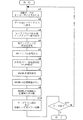
図5は、本発明の第1実施形態を説明するためのフローチャートである。なお、所定のパラメータを反射光量比HS/HLとして以下に説明する。図5に示したように、光ディスクDにデータを記録する際に、光ディスク記録装置1では、記録データがエンコーダ17に入力され、EFM変調される。そして、ストラテジ回路18で時間軸補正処理等が行われ、レーザドライバ19に出力される(s1)。
【0062】
また、この時、最適な記録レーザパワーで光ピックアップ10からレーザ光を照射するために、システム制御部16はレーザパワー制御回路20へ所定の信号を出力する。レーザパワー制御回路20は、システム制御部16の信号に基づき、所定の信号をレーザドライバ19に出力する(s2)。
【0063】
そして、レーザドライバ19は、ストラテジ回路18から出力された信号と、レーザパワー制御回路20から出力された信号と、に基づいた信号を光ピックアップ10に出力する(s3)。
【0064】
光ピックアップ10は、記録するデータに応じたレーザパワーで光ディスクDにレーザ光を照射し、その反射光を光受光素子で受光して、RFアンプ12に出力する(s4)。
【0065】
RFアンプ12は、受光したレーザ光の反射光量に応じた信号を反射光量比検出回路25へ出力する(s5)。
【0066】
反射光量比検出回路25は、前記反射光量のピーク値(実測値)HL、及びピーク値を過ぎて略安定した状態における反射光量の安定値(実測値)HSを検出する(s6)。そして、反射光量のピーク値と安定値との比HS/HL(ROPCサーボの実測値)を演算して、システム制御部16にその信号を出力する(s7)。システム制御部16は、記憶部27で記憶している反射光量比HS/HLの目標値を内蔵するRAMに読み出す(s8)。反射光量比検出回路25から送信された実測値と、前記RAMに読み出した目標値と、を比較し、その差を求める(s9)。そして、記憶部27で記憶している反射光量比HS/HLの実測値と目標値との差と記録レーザパワーの増減指示情報、反射光量比HS/HLの実測値とROPCサーボゲイン設定情報、及び前記求めた反射光量比HS/HLの実測値と目標値との差に応じて、所定の信号をレーザパワー制御回路20に出力して、レーザパワーを制御する(s10)。システム制御部16は、記録データが無くなるまでROPCを継続して、レーザパワーを制御する(s11)。記録データが無くなると、この処理を終了する。
【0067】
次に、本発明の第2実施形態について説明する。本発明の第2実施形態では、第1実施形態における予め記憶しておいたROPCサーボの目標値を得るため、又はROPCサーボのゲインを制御するために、OPCを行って求めた記録レーザパワーとROPCサーボの実測値の測定結果を指標として用いる。図6は、OPCの実施方法の一例を示したグラフである。OPCの実施方法としては様々な方法があるが、例えば、図6(A)に示したように、1回のテスト記録を行う際に、記録レーザパワーを15段階に変化させて行い、1つの記録レーザパワーにつき1サブコードフレーム分のEFM信号を記録し、合計15サブコードフレーム(15/75sec)分のEFM信号を記録する。このとき、図6(B)に示したように、各フレームで変化させている記録レーザパワーに対するROPCサーボの実測値を求めておけば、記録レーザパワーとROPCサーボの実測値の関係を知ることができる。
【0068】
そして、このデータを再生して得られた15ポイントの再生信号品位(例えば、β値)から、図6(C)に示したように、記録レーザパワーPとβ値の関係を求める。そして、所定の評価基準(例えば、予め記憶している目標β値と、記録レーザパワーPとβ値の関係と、の交点)に従って最適な記録レーザパワーPoを決定する。そして、ここで求めた最適な記録レーザパワーPo、及び図6(B)の記録レーザパワーとROPCサーボの実測値の関係と、の交点から、ROPCサーボの目標値を求めることができる。
【0069】
続いて、OPCで求めた記録レーザパワーPoで、データの本記録を開始する。このとき、光ディスクに反り、面振れ、感度ムラなどがあると、OPCで求めた記録レーザパワーPoで記録しても、現在記録している位置でのROPCサーボの実測値は、OPCで求めた実測値と異なったものになる。このような場合、記録したデータの再生信号品位は、OPCの試し書きデータの再生信号品位とは異なり、悪化してしまう。そこで、ROPCをできるだけ早く効かせなければならない。記録を開始した記録レーザパワー、つまりOPCで求めた記録レーザパワーPoでデータを記録している現在のROPCサーボの実測値と、OPCを行って求めた図6(B)の記録レーザパワーPとROPCサーボの実測値と、の関係から、現在記録している位置でのROPCサーボの目標値に相当する記録レーザパワーを推測することができる。また、同時に、現在の記録レーザパワーと、現在記録している位置でのROPCサーボの目標値に相当する記録レーザパワーと、の差は、何mWとなるかが推測できる。
【0070】
したがって、この記録レーザパワーの差(推測値)を求めて、この推測値を指標としてROPCサーボのゲインを変更する。このようにしてサーボ制御を行うことで、レーザ記録レーザパワーとROPCサーボの実測値との関係を予め実験などにより求めておかなくても、ROPCサーボの実測値と目標値との差に応じてROPCサーボのゲインを変更し、記録レーザパワーを制御することができる。
【0071】
図7は、本発明の第2実施形態を説明するためのフローチャートである。
【0072】
光ディスクDにデータを記録する場合、まず、システム制御部16は、OPCを実施する。すなわち、記憶部27が記憶しているOPCの実施パターンをRAMに読み出して、このパターンデータをエンコーダ17で符号化してストラテジ回路18を介してレーザドライバ19に送信する(s21)。また、このOPCの実施パターンデータに基づいて、光ピックアップ10の記録レーザパワーを制御するために、レーザパワー制御回路20に所定の信号を出力する(s22)。
【0073】
レーザドライバ19は、ストラテジ回路18及びレーザパワー制御回路20からの信号に基づいて、光ピックアップ10のレーザダイオードを制御して、OPC用データを光ディスクDのPCAに記録させる。例えば、OPCの実施パターンが図6(A)に示したようなパターンの場合、記録レーザパワーを15段階に変化させて行い、1つの記録レーザパワーにつき1サブコードフレーム分のEFM信号を記録し、合計15サブコードフレーム(15/75sec)分のEFM信号を記録する(s23)。
【0074】
そして、図6(B)に示したような記録レーザパワーとROPCサーボの実測値の関係を求める(s24)。
【0075】
この試し書きデータを再生して、RFアンプ12は再生信号をβ検出回路24に出力する。β検出回路は、β値を検出してシステム制御部16に出力する。システム制御部16は、図6(C)に示したような記録レーザパワーPとβ値の関係を求める(s25)。システム制御部16は、予め記憶部27で記憶している目標β値と、記録レーザパワーPとβ値の関係と、の交点から、最適な記録レーザパワーPoを決定する(s26)。そして、システム制御部16は、最適な記録レーザパワーPoと、図6(B)に示したような記録レーザパワーとROPCサーボの実測値の関係と、の交点からROPCサーボの目標値を決定する(s27)。
【0076】
続いて、データの本記録を行う。まず、光ディスクDにデータを記録する際に、光ディスク記録装置1では、記録データはエンコーダ17に入力され、EFM変調される。そして、ストラテジ回路18で時間軸補正処理等が行われ、レーザドライバ19に出力される(s28)。また、この時、OPCで求めた最適なレ ーザパワーPoで光ピックアップ10からレーザ光を照射するために、システム制御部16はエンコーダ17へ所定の信号を出力する。レーザパワー制御回路20は、システム制御部16の信号に基づき、所定の信号をレーザドライバ19に出力する(s29)。
【0077】
そして、レーザドライバ19は、ストラテジ回路18から出力された信号と、レーザパワー制御回路20から出力された信号と、に基づいた信号を光ピックアップ10に出力する(s30)。光ピックアップ10は、光ディスクDに記録するデータに応じた記録レーザパワーのレーザ光を照射する(s31)。
【0078】
そして、光ピックアップ10は、光ディスクDに記録レーザパワーでレーザ光を照射し、その反射光を光受光素子で受光して、反射光量に応じた信号をRFアンプ12に出力する(s32)。RFアンプ12は、受光したレーザ光の反射光量に応じた信号を反射光量比検出回路25へ出力する(s33)。反射光量比検出回路25は、記録中である現在の位置でのROPCサーボの実測値を、システム制御部16に出力する(s34)。
【0079】
システム制御部16は、記録中である現在の位置でのROPCサーボの実測値と、OPCを行って求めた図6(B)の記録レーザパワーPとROPCサーボの実測値と、の関係から、記録中である現在の位置でのROPCサーボの目標値に相当する記録レーザパワーを推測する(s35)。更に、この目標値に相当する記録レーザパワーの推測値と、記録中である現在の記録レーザパワーの設定値から、その差を求める(s36)。
【0080】
システム制御部16は、この差に応じてROPCサーボのゲインを設定し、所定の信号をレーザパワー制御回路20に出力して、光ピックアップ10のレーザ光の記録レーザパワーを制御する(s37)。
【0081】
システム制御部16は、データの記録が完了するまで、前記動作(s28〜s37)を繰り返す(s38)。
【0082】
また、前記第2の実施形態として、レーザパワーを制御する指標として、ROPCサーボの目標値に相当する記録レーザパワーの推測値と、記録中である現在の記録レーザパワーの設定値と、の差を用いたが、第1の実施形態のようにROPCサーボの実測値と、目標値と、の差を用いても良い。つまり、OPCで求めたROPCサーボの目標値と、記録中である現在のROPCサーボの実測値と、の差を用いることもできる。
【0083】
記録レーザパワーを制御する指標として、再生信号品位、例えばβ値を用いることもできる。つまり、ROPCサーボの実測値と、OPCで求めた又は予め記憶している図6(B)に示したような記録レーザパワーPとROPCサーボの実測値の関係と、図6(C)に示したような記録レーザパワーPとβ値の関係と、から現在記録している位置でのβ値を推測する。推測したβ値と、予め記憶している目標βと、の差に応じて、ROPCサーボのゲインを変更し、記録レーザパワーを制御する。
【0084】
また、記録レーザパワーを制御する指標としての再生信号品位として、HF変調度、HF振幅などを用いることもできる。この場合、β値をHF変調度、HF振幅値などに置き換えれば良い。
【0085】
さらに、記録レーザパワーを制御する指標として、上記以外の再生信号品位、C1エラー値やジッタ値を用いることもできる。なお、周知のように、C1エラー値とは、CDのエラー訂正機構に用いられているエラー訂正符号の一つであり、データ再生時にC1符号でエラー検出・訂正した際に訂正できなかったエラー数である。また、ジッタ値は、時間間隔分析によって測定した特定のピット又はランド(ブランク)の時間量のばらつき(標準偏差)である。
【0086】
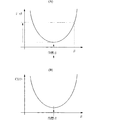
図8(A)はβ値とジッタ値との関係、図8(B)はβ値とC1エラー値との関係、を示したグラフである。β値は、再生信号品位を計るパラメータの1つであるが、図8に示したようにジッタ値やC1エラー値は、β値に対して二次関数的に変化(悪化)するため、通常はジッタ値やC1エラー値が最小値となるβ値を目標β値として選択する。しかし、このβ値は、光ディスクに反り、面振れ、感度ムラなどがあると、記録レーザパワーは一定値であったとしても、β値は一定値にならない。したがって、このような場合、β値がずれることによってジッタ値やC1エラー値が大きくなり、再生信号品位が悪化する。このように、再生信号品位が悪化すると、光ディスクに記録したデータは読めなくなり、データとして意味をなさなくなる。よって、光ディスクにデータを記録する際には、β値が目標β値に一定に保たれるようにしなければならない。
【0087】
図9(A)は記録レーザパワーとジッタ値との関係、図9(B)は記録レーザパワーとC1エラー値との関係、を示したグラフである。図9に示したように、記録レーザパワーに対して、ジッタ値、及びC1エラー値は、二次関数的に変化する。図9に示したような記録レーザパワーとジッタ値との関係、又は記録レーザパワーとC1エラー値との関係は、OPCを行って取得したデータから求めておく。または、図8に示したβ値とジッタ値との関係、又はβ値とC1エラー値との関係を予め実験などで求めておく。また、記録パワーとβ値との関係を、OPCを行って取得したデータから求める。そして、両者の関係から記録レーザパワーとジッタ値との関係、又は記録レーザパワーとC1エラー値との関係を求めるようにしても良い。
【0088】
この方法では、データの本記録の際に、ROPCサーボの実測値から推測したC1エラー値又はジッタ値の推測値と、C1エラー値又はジッタ値の目標値と、の差を推測することができるので、この差の値に基づいてROPCサーボゲインを設定し、記録レーザパワー制御をすることができる。つまり、現在のジッタ値(又は、C1エラー値)は、目標値に比べてこれだけ悪化しているだろうという指標から、ROPCサーボのゲインを設定し、記録レーザパワー制御をする。
【0089】
また、ジッタ値、C1エラー値などの再生信号品位を用いた場合は、前記のOPCで試し書き個所を再生する際に、β検出回路24でβ値を検出するだけでなく、デコーダ15のC1エラー検出回路23a又はジッタ検出回路23bなどで検出し、図8、図9に示した関係を求めれば良い。
【0090】
本発明のいずれの実施形態においても、光ディスクにデータを記録する速度に応じて、ROPCサーボゲインを変える(設定する)ことができる。特に、高速記録になるほど、光ディスクの反り、面振れ、感度ムラなどの変化速度が速くなるので、サーボゲインを一律に大きく設定すると良い。
【0091】
また、本発明のいずれの実施形態においても、データを記録する光ディスクの種類に応じて、ROPCサーボゲインを変える(設定する)ことができる。特に、光ディスクの反り、面振れ、感度ムラなどの変化量が大きい種類ほど、光ディスクの反り、面振れ、感度ムラなどの変化速度が速いので、サーボゲインを一律に大きく設定すると良い。
【0092】
【発明の効果】
本発明によれば、実測値と目標値との差が大きい時は、サーボ制御のゲインを大きくして記録レーザパワーを制御し、実測値と目標値との差が小さい時は、サーボ制御のゲインを小さくして記録レーザパワーを制御することで、実測値が発振したり、追従が遅くなったりすることなく、所定のパラメータ値を目標値へ速やかに収束させることができる。つまり、光ディスクの面振れ角、反り角、感度ムラなどの状態に応じて、実測値と目標値との差がどれだけ離れているかに関わらず、記録レーザパワーを短時間で補正して、データの再生信号品位を向上させることが可能となる。
【0093】
また、記録レーザパワーの設定値と所定のパラメータが目標値となる記録レーザパワーとの差が大きい時は、サーボ制御のゲインを大きくして記録レーザパワーを制御し、差が小さい時は、サーボ制御のゲインを小さくして記録レーザパワーを制御することで、所定のパラメータの実測値が発振したり、追従が遅くなったりすることなく、所定のパラメータを目標値へ速やかに収束させることができる。
【0094】
さらに、所定のパラメータの実測値における再生信号品位と再生信号品位の目標値との差が大きい時は、サーボ制御のゲインを大きくなるように記録レーザパワーを制御し、差が小さい時は、サーボ制御のゲインを小さくなるように記録レーザパワーを制御することで、所定のパラメータの実測値が発振したり、追従が遅くなったりすることなく、所定のパラメータを目標値へ速やかに収束させることができる。
【0095】
加えて、所定のパラメータの実測値における推定β値と目標β値との差が大きい時は、サーボ制御のゲインを大きくなるように記録レーザパワーを制御し、差が小さい時は、サーボ制御のゲインを小さくなるように記録レーザパワーを制御することで、所定のパラメータの実測値が発振したり、追従が遅くなったりすることなく、所定のパラメータを目標値へ速やかに収束させることができる。
【0096】
また、実測値及び目標値の差、推定値と設定値との差、又は推定値と目標値との差、に対するサーボゲインの設定値の記憶データ量を抑制することができる。
【図面の簡単な説明】
【図1】本発明の実施形態に係る光ディスク記録装置の構成を示したブロック図である。
【図2】光ディスクの領域構成を示した断面図である。
【図3】サーボゲインの応答性を示したグラフである。
【図4】ROPCサーボの実測値及び目標値の差と、ROPCサーボゲインとの関係を示したグラフである。
【図5】本発明の第1実施形態を説明するためのフローチャートである。
【図6】OPCの実施方法の一例、記録レーザパワーと実測値との関係、記録レーザパワーとβ値との関係、を示したグラフである。
【図7】本発明の第2実施形態を説明するためのフローチャートである。
【図8】β値とジッタ値との関係、β値とC1エラー値との関係を示したグラフである。
【図9】記録レーザパワーとジッタ値との関係、記録レーザパワーとC1エラー値との関係を示したグラフである。
【図10】光ディスクにピットを形成してデータを記録する際の、記録用レーザ光の記録信号及び反射光の受光信号の波形図、並びに形成されるピットの概観図である。
【図11】時間の経過とともに、ランニングOPCの実測値がどのように変動するかを示したグラフである。
【符号の説明】
1−光ディスク記録装置
10−光ピックアップ
11−スピンドルモータ
13−サーボ回路
16−システムシステム制御部
20−レーザパワー制御回路
25−反射光量比検出回路
26−光ディスク保持機構[0001]
BACKGROUND OF THE INVENTION
The present invention relates to an optical disc recording method and an optical disc recording apparatus for improving the quality of a data reproduction signal to a write once optical disc and a rewritable optical disc.
[0002]
[Prior art]
As an optical disk capable of recording data, for example, a write-once optical disk capable of recording data once such as CD-R, DVD-R, and data such as CD-RW, DVD-RW, DVD + RW, DVD-RAM, etc. There are rewritable optical discs that can be rewritten. These optical discs are produced on strictly controlled lines. However, depending on the manufacturing method, or when production lots change or setup changes occur, dye components and alloy components used in the recording layer of optical discs. Variation occurs. In addition, the disc may be warped or run out in the manufacturing process of the optical disc, or depending on the usage environment of the user or the storage state of the disc, or the state of warpage or run out may change. If the optical disc has sensitivity unevenness, warpage, surface runout, etc. due to variations in the dye component or alloy component, even if the discs have the same model number, the data reproduction signal quality changes for each optical disc. In general, it is warped that the umbrella is deformed like an open shape, and when the optical disk is rotated once, the state that the recording surface fluctuates up and down according to the rotation angle is surface. It is a shake.
[0003]
The optical disk is held (chucked) by a turntable that is driven to rotate by a spindle motor, and data is recorded and reproduced. However, in some cases, since the optical disk is chucked in a tilted state, when data is recorded on the optical disk in this state, the quality of the reproduced signal of the data changes according to the position (rotation angle) of the optical disk, and is constant. Must not.
[0004]
Therefore, as a method for keeping the reproduction signal quality constant, OPC (Optimum Power Control) and Running OPC (Running OPC) are conventionally performed. OPC performed trial writing by irradiating a PCA (Power Calibration Area) of an optical disc with a laser beam of a predetermined pattern before recording data so that good reproduction signal quality could be obtained. This is a recording laser power determination method for reproducing data and determining an optimum laser power according to a certain evaluation criterion. ROPC detects the reflected light (return light) from the optical disk during data recording so that a certain reproduction signal quality can be obtained in the disk, and the recording laser obtained by OPC according to the detected reflected light. This is a method for correcting power. In this method, a predetermined parameter value is obtained based on the detected reflected light, and control is performed with a constant (a fixed value) servo gain so that the obtained parameter value becomes a predetermined target value set in advance. .
[0005]
As a parameter for controlling the recording laser power by performing the running OPC, various values can be used. However, past the peak value HL of the reflected light amount of the recording laser beam at the beginning of the irradiation, A method of applying servo so that the stable value HS of the reflected light amount of the recording laser beam in a substantially stable state is constant is described in the standard document (Orange Book), and this method is generally used. Yes.
[0006]
FIG. 10 is a waveform diagram of the recording signal of the recording laser beam and the received light signal of the reflected light when recording data by forming pits on the optical disc, and an overview of the pits formed. As shown in FIG. 10, when the recording signal is a pulse having a predetermined time width, the received light signal level of the reflected light becomes the peak value HL at the beginning of the irradiation of the recording laser light. This is because all the irradiation light for forming pits on the optical disk is reflected at the beginning of the irradiation of the laser light on the optical disk. Thereafter, as the pits are formed, the amount of reflected light gradually decreases, and the received light signal level of the reflected light becomes a substantially stable value HS. When the recording signal falls, the received light signal of the reflected light also falls.
[0007]
The light reception signal of the reflected light of the recording laser light irradiated on the optical disk shows such characteristics, and when running OPC is performed, the substantially stable value HS of the light reception signal level becomes a constant value. By monitoring the light reception signal waveform and controlling the power of the recording laser beam, the quality of the data reproduction signal can be improved.
[0008]
[Problems to be solved by the invention]
FIG. 11 is a graph showing how the measured value of the running OPC varies with time. However, conventionally, the servo gain when performing the servo control of the running OPC is a constant value (a fixed value) as described above. Therefore, as shown in FIG. 11A, when the difference between the actual value and the target value is large or when the constant value set as the servo gain is small, there is a problem that the tracking is very slow. . Further, as shown in FIG. 11B, there is a problem that oscillation easily occurs when the difference between the measured value and the target value is small or when the constant value set as the servo gain is large.
[0009]
As described above, in the conventional running OPC servo control, the measured value of the running OPC cannot be quickly set to the target value, and it takes time until the appropriate servo is applied, and the data reproduction signal quality deteriorates. There was a problem that.
[0010]
Also, if recording is performed while the chucking state of the optical disk on the turntable is poor, surface wobbling will occur, and even if OPC or running OPC is performed, recording is performed with a reproduction signal quality that prevents data from being reproduced. There was a case.
[0011]
Accordingly, the present invention has been made to solve the above problems, and an object of the present invention is to improve the reproduction signal quality of data recorded on an optical disk and record the data on the optical disk in an optimum state. And providing an optical disk recording apparatus.
[0012]
[Means for Solving the Problems]
The present invention has the following configuration as means for solving the above problems.
[0016]
(1) Servo control so that the measured value of a predetermined parameter obtained by running OPC becomes the target value of the parameter in order to adjust the recording laser power of the laser beam irradiated when data is recorded on the optical disk An optical disc recording method for
The target value of the parameter and the relationship between the parameter and the recording laser power are stored in advance or obtained by trial writing prior to the running OPC operation,
From the relationship and the measured value of the parameter, the recording laser power at the target value of the parameter is estimated,
Find the difference between the estimated recording laser power and the set recording laser power,
The servo control gain is changed according to the difference between both recording laser powers.
[0017]
Therefore, when there is a large difference between the set value of the recording laser power and the recording laser power at which the predetermined parameter is the target value, the servoControlIncrease the gain to control the recording laser power.ControlBy controlling the recording laser power by reducing the gain, it becomes possible to quickly converge the predetermined parameter to the target value without oscillating the measured value of the predetermined parameter or slowing down the follow-up. . In other words, the recording laser power can be corrected in a short time, regardless of how far the difference between the measured value of the predetermined parameter and the target value is, depending on conditions such as the surface deflection angle, warpage angle, and sensitivity unevenness of the optical disk. Thus, it is possible to improve the reproduction signal quality of data.
[0018]
(2) Servo control so that the measured value of a predetermined parameter obtained by running OPC becomes the target value of the parameter in order to adjust the recording laser power of the laser beam irradiated when data is recorded on the optical disk An optical disc recording method for
The target value of the parameter,
The relationship between the parameter and the reproduction signal quality, or the relationship between the parameter and the recording laser power, and the relationship between the recording laser power and the reproduction signal quality,
Target value of playback signal quality,
Is stored in advance or obtained prior to the running OPC operation by trial writing,
From the relationship and the measured value of the parameter, the reproduction signal quality at the measured value of the parameter is estimated,
The difference between the estimated reproduction signal quality and the reproduction signal quality target value is obtained,
The servo control gain is changed according to the difference between the two reproduction signal qualities.
[0019]
Therefore, if there is a large difference between the playback signal quality and the target value of the playback signal quality in the measured values of the specified parameters, the servoControlControl the recording laser power to increase the gain.ControlBy controlling the recording laser power so as to reduce the gain, it is possible to quickly converge the predetermined parameter to the target value without oscillating the measured value of the predetermined parameter or slowing down the follow-up. Become. In other words, the recording laser power can be corrected in a short time, regardless of how far the difference between the measured value of the predetermined parameter and the target value is, depending on conditions such as the surface deflection angle, warpage angle, and sensitivity unevenness of the optical disk. Thus, it is possible to improve the reproduction signal quality of data.
[0020]
(3) As the reproduction signal quality, any one of β value, HF modulation degree, HF amplitude value, jitter value, and C1 error value is used.
[0021]
Therefore, when there is a large difference between the estimated β value and the target β value in the measured value of the predetermined parameter, the servoControlControl the recording laser power to increase the gain.ControlBy controlling the recording laser power so as to reduce the gain, it is possible to quickly converge the predetermined parameter to the target value without oscillating the measured value of the predetermined parameter or slowing down the follow-up. Become. In other words, the recording laser power can be corrected in a short time, regardless of how far the difference between the measured value of the predetermined parameter and the target value is, depending on conditions such as the surface deflection angle, warpage angle, and sensitivity unevenness of the optical disk. Thus, it is possible to improve the reproduction signal quality of data. Further, the case of the HF modulation degree, the HF amplitude, the jitter value, and the C1 error value is the same as the case of the β value.
[0022]
(4) The gain of the servo control is continuously increased as the absolute value of the difference between the actually measured value and the target value, the difference between the estimated value and the set value, or the difference between the estimated value and the target value increases. Or, it is set to increase in a staircase shape.
[0023]
In this configuration, in order to adjust the recording laser power when data is recorded on the optical disc, servo control is performed so that an actual measurement value of a predetermined parameter obtained by running OPC becomes a target value of the parameter. , Servo of running OPCControlThe gain is an absolute value of the difference between the actual measurement value and the target value, the difference between the estimated recording laser power and the set recording laser power, or the difference between the estimated reproduction signal quality and the reproduction signal quality target value. In accordance with the above, it is set to increase continuously or stepwise. By setting in this way, the servo for the difference between the measured value and the target value, the difference between the estimated value and the set value, or the difference between the estimated value and the target valueControlIt is possible to suppress the amount of stored data of the gain setting value.
[0026]
(5) Servo control so that the measured value of a predetermined parameter obtained by running OPC becomes the target value of the parameter in order to adjust the recording laser power of the laser beam irradiated when data is recorded on the optical disk An optical disc recording device that performs
Laser light irradiation means for irradiating laser light when recording data on an optical disc; laser power control means for controlling the laser power of the laser light irradiation means;
Obtaining means for performing running OPC to obtain an actual measurement value of a predetermined parameter;
Storage means for storing the target value of the parameter and the relationship between the parameter and the recording laser power;
Estimating means for estimating the recording laser power at the target value of the parameter from the relationship and the measured value of the parameter;
A calculation means for obtaining a difference between the estimated recording laser power and the set recording laser power;
Servo gain control means for changing the gain of the servo control according to the calculation result of the calculation means.
[0027]
In this configuration, when data is recorded on the optical disc, the estimation unit determines the predetermined parameter from the measured value of the predetermined parameter acquired by the running OPC by the acquisition unit and the relationship between the predetermined parameter stored in the storage unit and the recording laser power. The recording laser power at which the above parameter is the target value is estimated. The difference between the estimated recording laser power and the recording laser power set in the laser power control means is calculated by the calculating means, and the servo control gain of the running OPC is controlled according to this difference. Therefore, (1) Is obtained.
[0028]
(6) Servo control so that the measured value of a predetermined parameter obtained by running OPC becomes the target value of the parameter in order to adjust the recording laser power of the laser beam irradiated when data is recorded on the optical disk An optical disc recording device that performs
Laser light irradiation means for irradiating laser light when recording data on an optical disc;
Laser power control means for controlling the laser power of the laser light irradiation means;
Obtaining means for performing running OPC to obtain an actual measurement value of a predetermined parameter;
Storage means for storing the target value of the parameter, the relationship between the parameter and the reproduction signal quality, the relationship between the parameter and the recording laser power, the relationship between the recording laser power and the reproduction signal quality, and the target value of the reproduction signal quality ,
Estimating means for estimating reproduction signal quality at the measured value of the parameter from the relationship and the measured value of the parameter;
A calculation means for obtaining a difference between the estimated recording / reproducing signal quality and a target value of the reproduced signal quality;
Servo gain control means for changing the servo control gain in accordance with the calculation result of the calculation means.
[0029]
In this configuration, when data is recorded on the optical disc, the actual value of the predetermined parameter acquired by the running OPC by the acquisition unit, the relationship between the predetermined parameter stored in the storage unit and the reproduction signal quality, or the predetermined parameter And the recording laser power, and the relationship between the recording laser power and the reproduction signal quality, the reproduction signal quality is estimated by the estimating means. The difference between the estimated reproduction signal quality and the target value of the reproduction signal quality is calculated by the calculation means, and the servo of the running OPC is calculated according to this difference.ControlControl the gain. Therefore, the same effect as (2) can be obtained.
[0030]
(7The storage means stores one of a β value, an HF modulation degree, an HF amplitude value, a jitter value, and a C1 error value as the reproduction signal quality.
[0031]
In this configuration, any one of the β value, the HF modulation degree, the HF amplitude value, the jitter value, and the C1 error value is used as the reproduction signal quality, and the reproduction intention signal quality is estimated by the estimation means. The difference between the estimated reproduction signal quality and the target value of the reproduction signal quality is calculated by the calculation means, and the servo of the running OPC is calculated according to this difference.ControlControl the gain. Therefore, (3) Is obtained.
[0032]
(8) The servo gain control means continuously increases the absolute value of the difference between the measured value and the target value, the difference between the estimated value and the set value, or the difference between the estimated value and the target value. The servo control gain is set so as to increase in a stepwise or stepwise manner.
[0033]
In this configuration, in order to adjust the recording laser power when data is recorded on the optical disc, servo control is performed so that an actual measurement value of a predetermined parameter obtained by running OPC becomes a target value of the parameter. The running OPC servo control gain is the difference between the measured value and the target value, the difference between the estimated recording laser power and the set recording laser power, or the estimated reproduction signal quality and the target value of the reproduction signal quality. As the absolute value of the difference increases, the servo control gain of the running OPC is controlled so as to increase continuously or stepwise. Therefore, (4) Is obtained.
[0034]
DETAILED DESCRIPTION OF THE INVENTION
FIG. 1 is a block diagram showing a configuration of an optical disk recording apparatus according to an embodiment of the present invention. As shown in FIG. 1, the optical disk recording apparatus 1 includes an
[0035]
The
[0036]
The
[0037]
The RF amplifier 12 amplifies the EFM-modulated RF signal supplied from the
[0038]
During reproduction, the
[0039]
Optical disc according to this embodimentRecordWhen recording data, the apparatus 1 performs test recording in the PCA area on the inner periphery side of the optical disc D prior to the main recording. Then, based on the reproduction result of the test-recorded area, a recording laser power capable of obtaining a good reproduction signal quality for the optical disc D is obtained. The C1
[0040]
Here, an area for test recording on the optical disc D will be described with reference to FIG. FIG. 2 is a cross-sectional view showing the area configuration of the optical disc. The outer diameter of the optical disk D is 120 mm, the section of the optical disk D having a diameter of 46 to 50 mm is prepared as the lead-in area 114, and the program area 118 and the remaining area 120 for recording data are prepared on the outer peripheral side. On the other hand, an inner peripheral side PCA 112 is prepared on the inner peripheral side of the lead-in area 114. The inner peripheral side PCA 112 is provided with a test area 112a and a count area 112b. As described above, test recording is performed in the test area 112a prior to the main recording. Here, an area where test recording can be performed a plurality of times is prepared as the test area 112a. In the count area 112b, an EFM signal indicating how much of the test area 112a has been recorded at the end of the test recording is recorded. Therefore, when performing test recording on the optical disc D next time, it is possible to know from which position in the test area 112a test recording should be started by reading the EFM signal in the count area 112b. Yes. In the optical disk recording apparatus 1 according to the present embodiment, test recording is performed in the test area 112a before the main recording of data.
[0041]
Returning to FIG. 1, the
[0042]
The
[0043]
The
[0044]
The reflected light amount
[0045]
Note that the peak value HL of the reflected light amount from the original optical disk that started the irradiation of the recording laser beam is substantially proportional to the irradiation laser power (recording laser power) and the reflectance of the disk, so the peak value of the reflected light amount HL is approximately proportional to the recording laser power. Therefore, instead of using the peak value HL of the amount of reflected light, the recording laser power value can be used as a corresponding value. Further, as the recording laser power value, a set value (command value) of the recording laser power or a detected value of the recording laser power can be used.
[0046]
The
[0047]
The
[0048]
The laser
[0049]
The
[0050]
As described above, the
[0051]
An operation at the time of data recording on the optical disc D in the optical disc recording apparatus 1 configured as described above will be described. First, in the first embodiment of the present invention, a recording laser power of a recording laser beam irradiated when data is recorded on an optical disk is subjected to running OPC (hereinafter referred to as ROPC) and servoed by a method different from the conventional method. Control. That is, an actual measurement value of a predetermined parameter obtained by performing ROPC (hereinafter referred to as an actual measurement value or an actual measurement value of ROPC servo) and a target value of a predetermined parameter (hereinafter referred to as an ROPC servo target value or target value). The servo gain when ROPC is performed (hereinafter referred to as ROPC servo gain or servo gain) is changed in accordance with the difference between the data and the optical disc.
[0052]
Specifically, when the difference between the actually measured value of the ROPC servo and the target value of the ROPC servo is large, the ROPC servo gain is increased to control the recording laser power of the recording laser beam. When the difference between the actual value of the ROPC servo and the target value of the ROPC servo is small, the ROPC servo gain is reduced to control the recording laser power of the recording laser beam.
[0053]
As in the past, not only the difference between the measured value and target value of the ROPC servo and the increase / decrease relationship of the recording laser power, but also the difference between the measured value and target value of the ROPC servo and the gain of the ROPC servo. As for the relationship, an optimum value is obtained by conducting an experiment or the like in advance, and the servo gain is changed based on this data.
[0054]
FIG. 3 is a graph showing the response of the servo gain. As shown in FIG. 3A, when the difference between the measured value of the ROPC servo and the target value of the ROPC servo is large or the ROPC servo gain is small, the servo gain is constant in the conventional method as described above. Therefore, the actual measurement value did not converge to the target value, but in the present invention, the actual measurement value converges to the target value in a shorter time than in the past.
[0055]
Further, as shown in FIG. 3B, when the difference between the measured value of the ROPC servo and the target value of the ROPC servo is small or the ROPC servo gain is large, the servo gain is increased in the conventional method as described above. Since it was constant, it seemed to oscillate, but in the present invention, the measured value converges to the target value in a short time without oscillating.
[0056]
Therefore, by using the present invention, it is possible to control the recording laser power so that the convergence speed can be quickly converged to the target value of the ROPC servo without slowing down or oscillating.
[0057]
FIG. 4 is a graph showing the relationship between the difference between the measured value and the target value of the ROPC servo and the ROPC servo gain. Here, as shown in FIG. 4A, the gain of the ROPC servo is set so as to change continuously as the absolute value of the difference between the measured value of the ROPC servo and the target value increases. be able to.
[0058]
Further, as shown in FIG. 4B, the gain of the ROPC servo can be set so as to change stepwise as the absolute value of the difference between the actually measured value and the target value increases. That is, the servo gain is set to be constant for each region (zone), and the servo gain is increased by a predetermined value for each region as the absolute value of the difference between the actual measurement value and the target value increases. It can also be set to increase. By setting in this way, the amount of data stored in the servo gain setting value with respect to the difference between the actual measurement value and the target value can be suppressed.
[0059]
Specifically, as the target value and the actual measurement value of the ROPC servo, arbitrary parameters can be set. For example, the peak value HL of the reflected light amount in the received light signal waveform of the recording laser beam shown in FIG. The reflected light quantity ratio HS / HL of the reflected light quantity stable value HS of the recording laser light in a substantially stable state after the peak value can be used. In this case, the servo is applied to control the recording laser power so that the reflected light quantity ratio HS / HL becomes the target value stored in advance.
[0060]
The reflected light quantity ratio HS / HL is an example of a parameter set to the ROPC target value, and other parameters can be applied. For example, since the peak value HL (peak portion of the recording waveform) of the reflected light amount is a value that is substantially proportional to the recording laser power, the reflected light amount stable value HS / recording laser power is used as a parameter for setting the ROPC target value. You can also. Even when this parameter is used, the same control as when the reflected light amount ratio HS / HL is used may be performed.
[0061]
FIG. 5 is a flowchart for explaining the first embodiment of the present invention. The predetermined parameter will be described below as the reflected light quantity ratio HS / HL. As shown in FIG. 5, when data is recorded on the optical disc D, the optical disc recording apparatus 1 inputs the recording data to the
[0062]
At this time, the
[0063]
Then, the
[0064]
The
[0065]
The RF amplifier 12 outputs a signal corresponding to the reflected light amount of the received laser beam to the reflected light amount ratio detection circuit 25 (s5).
[0066]
The reflected light amount
[0067]
Next, a second embodiment of the present invention will be described. In the second embodiment of the present invention, in order to obtain the ROPC servo target value stored in advance in the first embodiment or to control the gain of the ROPC servo, the recording laser power obtained by performing OPC is used. The measurement result of the actual measurement value of the ROPC servo is used as an index. FIG. 6 is a graph showing an example of an OPC implementation method. There are various methods for performing the OPC. For example, as shown in FIG. 6A, when performing test recording once, the recording laser power is changed in 15 stages. EFM signals for one subcode frame are recorded for each recording laser power, and EFM signals for a total of 15 subcode frames (15/75 sec) are recorded. At this time, as shown in FIG. 6B, if the actual measurement value of the ROPC servo with respect to the recording laser power changed in each frame is obtained, the relationship between the recording laser power and the actual measurement value of the ROPC servo is known. Can do.
[0068]
Then, from the 15-point reproduction signal quality (for example, β value) obtained by reproducing this data, as shown in FIG. 6C, the relationship between the recording laser power P and the β value is obtained. Then, the optimum recording laser power Po is determined in accordance with a predetermined evaluation criterion (for example, the intersection of the target β value stored in advance and the relationship between the recording laser power P and the β value). Then, the ROPC servo target value can be obtained from the optimum recording laser power Po obtained here and the intersection of the recording laser power and the measured value of the ROPC servo in FIG. 6B.
[0069]
Subsequently, the main recording of data is started at the recording laser power Po obtained by OPC. At this time, if the optical disk is warped, surface runout, sensitivity unevenness, etc., even if recording is performed with the recording laser power Po obtained by OPC, the actual measurement value of the ROPC servo at the current recording position is obtained by OPC. It will be different from the measured value. In such a case, the reproduction signal quality of the recorded data deteriorates unlike the reproduction signal quality of the OPC test writing data. Therefore, ROPC must be effective as soon as possible. The recording laser power at which recording is started, that is, the actual measured value of the current ROPC servo that records data with the recording laser power Po obtained by OPC, and the recording laser power P in FIG. 6B obtained by performing OPC. From the relationship with the actual measurement value of the ROPC servo, the recording laser power corresponding to the target value of the ROPC servo at the current recording position can be estimated. At the same time, it can be estimated how much mW the difference between the current recording laser power and the recording laser power corresponding to the ROPC servo target value at the current recording position is.
[0070]
Therefore, the difference (estimated value) of the recording laser power is obtained, and the gain of the ROPC servo is changed using this estimated value as an index. By performing servo control in this way, even if the relationship between the laser recording laser power and the measured value of the ROPC servo is not obtained in advance by an experiment or the like, according to the difference between the measured value of the ROPC servo and the target value. The gain of the ROPC servo can be changed to control the recording laser power.
[0071]
FIG. 7 is a flowchart for explaining the second embodiment of the present invention.
[0072]
When recording data on the optical disc D, the
[0073]
The
[0074]
Then, the relationship between the recording laser power and the actually measured value of the ROPC servo as shown in FIG. 6B is obtained (s24).
[0075]
The RF amplifier 12 reproduces the trial writing data and outputs a reproduction signal to the
[0076]
Subsequently, the main recording of data is performed. First, when data is recorded on the optical disc D, in the optical disc recording apparatus 1, the recording data is input to the
[0077]
Then, the
[0078]
Then, the
[0079]
The
[0080]
The
[0081]
The
[0082]
In the second embodiment, as an index for controlling the laser power, the difference between the estimated value of the recording laser power corresponding to the target value of the ROPC servo and the set value of the current recording laser power during recording However, the difference between the measured value of the ROPC servo and the target value may be used as in the first embodiment. That is, the difference between the ROPC servo target value obtained by OPC and the current measured value of the ROPC servo being recorded can also be used.
[0083]
As an index for controlling the recording laser power, reproduction signal quality, for example, β value can be used. That is, the relationship between the actually measured value of the ROPC servo, the recording laser power P obtained by OPC or stored in advance as shown in FIG. 6B, and the actually measured value of the ROPC servo, as shown in FIG. 6C. The β value at the current recording position is estimated from the relationship between the recording laser power P and the β value. The gain of the ROPC servo is changed according to the difference between the estimated β value and the target β stored in advance, and the recording laser power is controlled.
[0084]
Further, the HF modulation degree, the HF amplitude, and the like can be used as the reproduction signal quality as an index for controlling the recording laser power. In this case, the β value may be replaced with an HF modulation degree, an HF amplitude value, or the like.
[0085]
Further, as an index for controlling the recording laser power, a reproduction signal quality other than the above, a C1 error value, and a jitter value can be used. As is well known, the C1 error value is one of error correction codes used in the CD error correction mechanism, and an error that could not be corrected when the error was detected and corrected with the C1 code during data reproduction. Is a number. The jitter value is a variation (standard deviation) in the amount of time of a specific pit or land (blank) measured by time interval analysis.
[0086]
FIG. 8A is a graph showing the relationship between the β value and the jitter value, and FIG. 8B is a graph showing the relationship between the β value and the C1 error value. The β value is one of the parameters for measuring the reproduction signal quality. However, as shown in FIG. 8, since the jitter value and the C1 error value change (deteriorate) in a quadratic function with respect to the β value, Selects the β value at which the jitter value and the C1 error value are minimum values as the target β value. However, if this β value is warped on the optical disk, and there is surface vibration, sensitivity unevenness, etc., even if the recording laser power is a constant value, the β value does not become a constant value. Therefore, in such a case, the jitter value and the C1 error value increase due to the deviation of the β value, and the reproduction signal quality deteriorates. As described above, when the reproduction signal quality deteriorates, the data recorded on the optical disc cannot be read, and the data becomes meaningless. Therefore, when data is recorded on the optical disc, the β value must be kept constant at the target β value.
[0087]
FIG. 9A is a graph showing the relationship between the recording laser power and the jitter value, and FIG. 9B is a graph showing the relationship between the recording laser power and the C1 error value. As shown in FIG. 9, the jitter value and the C1 error value change in a quadratic function with respect to the recording laser power. The relationship between the recording laser power and the jitter value as shown in FIG. 9 or the relationship between the recording laser power and the C1 error value is obtained from data acquired by performing OPC. Alternatively, the relationship between the β value and the jitter value or the relationship between the β value and the C1 error value shown in FIG. Further, the relationship between the recording power and the β value is obtained from the data obtained by performing OPC. Then, the relationship between the recording laser power and the jitter value or the relationship between the recording laser power and the C1 error value may be obtained from the relationship between the two.
[0088]
In this method, the difference between the estimated value of the C1 error value or jitter value estimated from the actually measured value of the ROPC servo and the target value of the C1 error value or jitter value can be estimated at the time of actual recording of data. Therefore, the ROPC servo gain can be set based on the difference value, and the recording laser power can be controlled. That is, the ROPC servo gain is set and the recording laser power control is performed based on the index that the current jitter value (or C1 error value) will be deteriorated by this amount compared to the target value.
[0089]
When the reproduction signal quality such as jitter value and C1 error value is used, not only the β value is detected by the
[0090]
In any embodiment of the present invention, the ROPC servo gain can be changed (set) in accordance with the speed at which data is recorded on the optical disc. In particular, the higher the recording speed, the faster the change speed of the optical disc warp, surface shake, sensitivity unevenness, etc., so it is better to set the servo gain to be uniformly large.
[0091]
In any of the embodiments of the present invention, the ROPC servo gain can be changed (set) in accordance with the type of optical disk on which data is recorded. In particular, the larger the amount of change such as the warp, surface shake, and sensitivity unevenness of the optical disk, the faster the change rate of the optical disk warp, surface shake, sensitivity unevenness, etc., so it is preferable to set the servo gain uniformly high.
[0092]
【The invention's effect】
According to the present invention, when the difference between the measured value and the target value is large, the servoControlWhen the gain is increased and the recording laser power is controlled and the difference between the measured value and the target value is small, the servo isControlBy controlling the recording laser power by reducing the gain, it is possible to quickly converge the predetermined parameter value to the target value without oscillating the actual measurement value or slowing down the follow-up. In other words, the recording laser power can be corrected in a short period of time regardless of how far the difference between the measured value and the target value is, depending on the state of the optical disc surface deflection angle, warpage angle, sensitivity unevenness, etc. It is possible to improve the quality of the reproduced signal.
[0093]
When the difference between the set value of the recording laser power and the recording laser power at which the predetermined parameter is the target value is large, the servoControlIncrease the gain to control the recording laser power.ControlBy controlling the recording laser power by reducing the gain, it is possible to quickly converge the predetermined parameter to the target value without oscillating the measured value of the predetermined parameter or slowing down the follow-up.
[0094]
In addition, if the difference between the reproduced signal quality and the target value of the reproduced signal quality in the measured value of a given parameter is large, the servoControlControl the recording laser power to increase the gain.ControlBy controlling the recording laser power so as to reduce the gain, it is possible to quickly converge the predetermined parameter to the target value without oscillating the measured value of the predetermined parameter or slowing down the follow-up.
[0095]
In addition, if there is a large difference between the estimated β value and the target β value in the measured value of the specified parameter, the servoControlControl the recording laser power to increase the gain.ControlBy controlling the recording laser power so as to reduce the gain, it is possible to quickly converge the predetermined parameter to the target value without oscillating the measured value of the predetermined parameter or slowing down the follow-up.
[0096]
Further, it is possible to suppress the stored data amount of the servo gain set value with respect to the difference between the actual value and the target value, the difference between the estimated value and the set value, or the difference between the estimated value and the target value.
[Brief description of the drawings]
FIG. 1 is a block diagram showing a configuration of an optical disc recording apparatus according to an embodiment of the present invention.
FIG. 2 is a cross-sectional view showing an area configuration of an optical disc.
FIG. 3 is a graph showing the response of servo gain.
FIG. 4 is a graph showing a relationship between a difference between a measured value and a target value of a ROPC servo and a ROPC servo gain.
FIG. 5 is a flowchart for explaining the first embodiment of the present invention;
FIG. 6 is a graph showing an example of an OPC implementation method, a relationship between a recording laser power and an actually measured value, and a relationship between a recording laser power and a β value.
FIG. 7 is a flowchart for explaining a second embodiment of the present invention.
FIG. 8 is a graph showing the relationship between β value and jitter value, and the relationship between β value and C1 error value.
FIG. 9 is a graph showing the relationship between the recording laser power and the jitter value, and the relationship between the recording laser power and the C1 error value.
FIG. 10 is a waveform diagram of a recording signal of a recording laser beam and a received light signal of reflected light when recording data by forming pits on an optical disc, and an overview of the formed pits.
FIG. 11 is a graph showing how the measured value of the running OPC varies with time.
[Explanation of symbols]
1-Optical disk recording device
10-optical pickup
11-spindle motor
13-Servo circuit
16-System system controller
20-Laser power control circuit
25-reflected light quantity ratio detection circuit
26-Optical disk holding mechanism
Claims (8)
該パラメータの目標値、及び該パラメータと記録レーザパワーとの関係を、予め記憶しておくか、又は試し書きによりランニングOPCの動作に先立って求めておき、
前記関係と該パラメータの実測値から、該パラメータの目標値での記録レーザパワーを推測し、
該推定記録レーザパワーと、設定している記録レーザパワーと、の差を求め、
両記録レーザパワーの差に応じて前記サーボ制御のゲインを変更することを特徴とする光ディスク記録方法。In order to adjust the recording laser power of the laser beam irradiated when data is recorded on the optical disc, servo control is performed so that an actual measurement value of a predetermined parameter obtained by running OPC becomes a target value of the parameter. An optical disk recording method comprising:
The target value of the parameter and the relationship between the parameter and the recording laser power are stored in advance or obtained by trial writing prior to the running OPC operation,
From the relationship and the measured value of the parameter, the recording laser power at the target value of the parameter is estimated,
Find the difference between the estimated recording laser power and the set recording laser power,
An optical disk recording method, wherein the servo control gain is changed in accordance with a difference between both recording laser powers .
該パラメータの目標値、
該パラメータと再生信号品位との関係、又は該パラメータと記録レーザパワーとの関係及び記録レーザパワーと再生信号品位との関係、
再生信号品位の目標値、
を予め記憶しておくか、又は試し書きによりランニングOPCの動作に先立って求めておき、
前記関係と該パラメータの実測値から、該パラメータの実測値での再生信号品位を推測し、
該推定再生信号品位と、再生信号品位の目標値と、の差を求め、
両再生信号品位の差に応じて前記サーボ制御のゲインを変更することを特徴とする光ディスク記録方法。In order to adjust the recording laser power of the laser beam irradiated when data is recorded on the optical disc, servo control is performed so that an actual measurement value of a predetermined parameter obtained by running OPC becomes a target value of the parameter. An optical disk recording method comprising:
The target value of the parameter,
The relationship between the parameter and the reproduction signal quality, or the relationship between the parameter and the recording laser power, and the relationship between the recording laser power and the reproduction signal quality,
Target value of playback signal quality,
Is stored in advance or obtained prior to the running OPC operation by trial writing,
From the relationship and the measured value of the parameter, the reproduction signal quality at the measured value of the parameter is estimated,
The difference between the estimated reproduction signal quality and the reproduction signal quality target value is obtained,
An optical disk recording method, wherein the servo control gain is changed in accordance with a difference between both reproduction signal qualities .
光ディスクへデータを記録する際にレーザ光を照射するレーザ光照射手段と、 Laser light irradiation means for irradiating laser light when recording data on an optical disc;
該レーザ光照射手段のレーザパワーを制御するレーザパワー制御手段と、 Laser power control means for controlling the laser power of the laser light irradiation means;
ランニングOPCを行って所定のパラメータの実測値を取得する取得手段と、 Obtaining means for performing running OPC to obtain an actual measurement value of a predetermined parameter;
該パラメータの目標値、及び該パラメータと記録レーザパワーとの関係を記憶する記憶手段と、 Storage means for storing the target value of the parameter and the relationship between the parameter and the recording laser power;
前記関係と該パラメータの実測値から該パラメータの目標値での記録レーザパワーを推測する推定手段と、 Estimating means for estimating the recording laser power at the target value of the parameter from the relationship and the measured value of the parameter;
該推定記録レーザパワーと設定している記録レーザパワーとの差を求める演算手段と、 A calculation means for obtaining a difference between the estimated recording laser power and the set recording laser power;
該演算手段の演算結果に応じて前記サーボ制御のゲインを変更するサーボゲイン制御手段と、を備えたことを特徴とする光ディスク記録装置。 An optical disk recording apparatus comprising: servo gain control means for changing a gain of the servo control according to a calculation result of the calculation means.
光ディスクへデータを記録する際にレーザ光を照射するレーザ光照射手段と、
該レーザ光照射手段のレーザパワーを制御するレーザパワー制御手段と、
ランニングOPCを行って所定のパラメータの実測値を取得する取得手段と、
該パラメータの目標値、該パラメータと再生信号品位との関係、又は該パラメータと記録レーザパワーとの関係及び記録レーザパワーと再生信号品位との関係、再生信号品位の目標値を記憶する記憶手段と、
前記関係と該パラメータの実測値から該パラメータの実測値での再生信号品位を推測する推定手段と、
該推定記録再生信号品位と再生信号品位の目標値との差を求める演算手段と、
該演算手段の演算結果に応じて前記サーボ制御のゲインを変更するサーボゲイン制御手段と、を備えたことを特徴とする光ディスク記録装置。In order to adjust the recording laser power of the laser beam irradiated when data is recorded on the optical disc, servo control is performed so that an actual measurement value of a predetermined parameter obtained by running OPC becomes a target value of the parameter. An optical disk recording device,
Laser light irradiation means for irradiating laser light when recording data on an optical disc;
Laser power control means for controlling the laser power of the laser light irradiation means;
Obtaining means for performing running OPC to obtain an actual measurement value of a predetermined parameter;
Storage means for storing the target value of the parameter, the relationship between the parameter and the reproduction signal quality, the relationship between the parameter and the recording laser power, the relationship between the recording laser power and the reproduction signal quality, and the target value of the reproduction signal quality ,
Estimating means for estimating reproduction signal quality at the measured value of the parameter from the relationship and the measured value of the parameter;
A calculation means for obtaining a difference between the estimated recording / reproducing signal quality and a target value of the reproduced signal quality ;
An optical disk recording apparatus comprising: servo gain control means for changing the gain of the servo control according to a calculation result of the calculation means.
Priority Applications (1)
| Application Number | Priority Date | Filing Date | Title |
|---|---|---|---|
| JP2002083938A JP3994772B2 (en) | 2002-03-25 | 2002-03-25 | Optical disc recording method and optical disc recording apparatus |
Applications Claiming Priority (1)
| Application Number | Priority Date | Filing Date | Title |
|---|---|---|---|
| JP2002083938A JP3994772B2 (en) | 2002-03-25 | 2002-03-25 | Optical disc recording method and optical disc recording apparatus |
Publications (3)
| Publication Number | Publication Date |
|---|---|
| JP2003281727A JP2003281727A (en) | 2003-10-03 |
| JP2003281727A5 JP2003281727A5 (en) | 2005-08-18 |
| JP3994772B2 true JP3994772B2 (en) | 2007-10-24 |
Family
ID=29231493
Family Applications (1)
| Application Number | Title | Priority Date | Filing Date |
|---|---|---|---|
| JP2002083938A Expired - Fee Related JP3994772B2 (en) | 2002-03-25 | 2002-03-25 | Optical disc recording method and optical disc recording apparatus |
Country Status (1)
| Country | Link |
|---|---|
| JP (1) | JP3994772B2 (en) |
Families Citing this family (3)
| Publication number | Priority date | Publication date | Assignee | Title |
|---|---|---|---|---|
| KR101027402B1 (en) * | 2004-11-16 | 2011-04-11 | 주식회사 히타치엘지 데이터 스토리지 코리아 | Method for controlling servo for blank disk |
| KR100652387B1 (en) | 2004-11-30 | 2006-12-01 | 삼성전자주식회사 | Writing test apparatus and method using charge pump in optical disk reproducing and recording apparatus |
| JP4513750B2 (en) | 2005-11-18 | 2010-07-28 | ティアック株式会社 | Optical disk device |
-
2002
- 2002-03-25 JP JP2002083938A patent/JP3994772B2/en not_active Expired - Fee Related
Also Published As
| Publication number | Publication date |
|---|---|
| JP2003281727A (en) | 2003-10-03 |
Similar Documents
| Publication | Publication Date | Title |
|---|---|---|
| US7046600B2 (en) | Optical disc apparatus with laser power control matching linear recording velocity | |
| US6975572B2 (en) | Optical disc apparatus with regulation of recording velocity and laser power | |
| US7046599B2 (en) | Optical disc recording method and optical disc recording apparatus for setting optimal recording power to record data | |
| JP2002288831A (en) | Optical disk apparatus | |
| JP3979120B2 (en) | Optical disk device | |
| JP3801000B2 (en) | Optical disk device | |
| JP2002042339A (en) | Optical disk recorder | |
| KR100943980B1 (en) | Optical recording apparatus, optical reproduction apparatus, recording medium recording method, and recording medium reproduction method | |
| US7053919B2 (en) | Optical disk apparatus of variable recording velocity with optimum power control | |
| JP3736369B2 (en) | Optical disc recording laser power determination method and optical disc recording apparatus | |
| JP4580367B2 (en) | Recording power adjusting method and optical recording / reproducing apparatus | |
| JP3994772B2 (en) | Optical disc recording method and optical disc recording apparatus | |
| JP4048972B2 (en) | Laser power adjustment method and disk drive device | |
| JP3846249B2 (en) | Optical disk recording device | |
| JP4460569B2 (en) | Optical disc apparatus and recording power setting method thereof | |
| JP3773196B2 (en) | RECORDING / REPRODUCING DEVICE AND LASER POWER CONTROL METHOD FOR CAV RECORDING | |
| JP3938075B2 (en) | Optical disc recording method and optical disc recording apparatus | |
| JP2003331427A (en) | Optical information recording and reproducing device | |
| JP3873722B2 (en) | Optical disk device | |
| JP4218596B2 (en) | Optical disk device | |
| JP4389880B2 (en) | Optical recording medium recording circuit, optical recording medium recording apparatus, and laser beam intensity adjusting method | |
| JP3865123B2 (en) | Optical intensity control device and optical intensity control method for optical disc apparatus | |
| JP2002312939A (en) | Optimum power deciding method for optical disk, and optical recorder | |
| JP2003132537A (en) | Laser beam control method, test recording method, and optical recording device | |
| JP2002216350A (en) | Recording device |
Legal Events
| Date | Code | Title | Description |
|---|---|---|---|
| A621 | Written request for application examination |
Free format text: JAPANESE INTERMEDIATE CODE: A621 Effective date: 20041102 |
|
| A521 | Written amendment |
Free format text: JAPANESE INTERMEDIATE CODE: A523 Effective date: 20050128 |
|
| A977 | Report on retrieval |
Free format text: JAPANESE INTERMEDIATE CODE: A971007 Effective date: 20070402 |
|
| A131 | Notification of reasons for refusal |
Free format text: JAPANESE INTERMEDIATE CODE: A131 Effective date: 20070417 |
|
| A521 | Written amendment |
Free format text: JAPANESE INTERMEDIATE CODE: A523 Effective date: 20070618 |
|
| TRDD | Decision of grant or rejection written | ||
| A01 | Written decision to grant a patent or to grant a registration (utility model) |
Free format text: JAPANESE INTERMEDIATE CODE: A01 Effective date: 20070710 |
|
| A61 | First payment of annual fees (during grant procedure) |
Free format text: JAPANESE INTERMEDIATE CODE: A61 Effective date: 20070723 |
|
| FPAY | Renewal fee payment (event date is renewal date of database) |
Free format text: PAYMENT UNTIL: 20100810 Year of fee payment: 3 |
|
| R150 | Certificate of patent or registration of utility model |
Free format text: JAPANESE INTERMEDIATE CODE: R150 |
|
| FPAY | Renewal fee payment (event date is renewal date of database) |
Free format text: PAYMENT UNTIL: 20100810 Year of fee payment: 3 |
|
| FPAY | Renewal fee payment (event date is renewal date of database) |
Free format text: PAYMENT UNTIL: 20100810 Year of fee payment: 3 |
|
| FPAY | Renewal fee payment (event date is renewal date of database) |
Free format text: PAYMENT UNTIL: 20110810 Year of fee payment: 4 |
|
| FPAY | Renewal fee payment (event date is renewal date of database) |
Free format text: PAYMENT UNTIL: 20120810 Year of fee payment: 5 |
|
| FPAY | Renewal fee payment (event date is renewal date of database) |
Free format text: PAYMENT UNTIL: 20130810 Year of fee payment: 6 |
|
| LAPS | Cancellation because of no payment of annual fees |