CN100429707C - Disc recording method and system - Google Patents
Disc recording method and system Download PDFInfo
- Publication number
- CN100429707C CN100429707C CNB2004100284419A CN200410028441A CN100429707C CN 100429707 C CN100429707 C CN 100429707C CN B2004100284419 A CNB2004100284419 A CN B2004100284419A CN 200410028441 A CN200410028441 A CN 200410028441A CN 100429707 C CN100429707 C CN 100429707C
- Authority
- CN
- China
- Prior art keywords
- data
- power
- record
- peak
- crosstalk
- Prior art date
- Legal status (The legal status is an assumption and is not a legal conclusion. Google has not performed a legal analysis and makes no representation as to the accuracy of the status listed.)
- Expired - Fee Related
Links
Images


Classifications
-
- G—PHYSICS
- G11—INFORMATION STORAGE
- G11B—INFORMATION STORAGE BASED ON RELATIVE MOVEMENT BETWEEN RECORD CARRIER AND TRANSDUCER
- G11B7/00—Recording or reproducing by optical means, e.g. recording using a thermal beam of optical radiation by modifying optical properties or the physical structure, reproducing using an optical beam at lower power by sensing optical properties; Record carriers therefor
- G11B7/12—Heads, e.g. forming of the optical beam spot or modulation of the optical beam
- G11B7/125—Optical beam sources therefor, e.g. laser control circuitry specially adapted for optical storage devices; Modulators, e.g. means for controlling the size or intensity of optical spots or optical traces
- G11B7/126—Circuits, methods or arrangements for laser control or stabilisation
- G11B7/1267—Power calibration
-
- G—PHYSICS
- G11—INFORMATION STORAGE
- G11B—INFORMATION STORAGE BASED ON RELATIVE MOVEMENT BETWEEN RECORD CARRIER AND TRANSDUCER
- G11B7/00—Recording or reproducing by optical means, e.g. recording using a thermal beam of optical radiation by modifying optical properties or the physical structure, reproducing using an optical beam at lower power by sensing optical properties; Record carriers therefor
- G11B7/004—Recording, reproducing or erasing methods; Read, write or erase circuits therefor
- G11B7/006—Overwriting
- G11B7/0062—Overwriting strategies, e.g. recording pulse sequences with erasing level used for phase-change media
-
- G—PHYSICS
- G11—INFORMATION STORAGE
- G11B—INFORMATION STORAGE BASED ON RELATIVE MOVEMENT BETWEEN RECORD CARRIER AND TRANSDUCER
- G11B7/00—Recording or reproducing by optical means, e.g. recording using a thermal beam of optical radiation by modifying optical properties or the physical structure, reproducing using an optical beam at lower power by sensing optical properties; Record carriers therefor
- G11B7/004—Recording, reproducing or erasing methods; Read, write or erase circuits therefor
- G11B7/0045—Recording
- G11B7/00458—Verification, i.e. checking data during or after recording
Landscapes
- Physics & Mathematics (AREA)
- Optics & Photonics (AREA)
- Optical Recording Or Reproduction (AREA)
- Optical Head (AREA)
Abstract
A crosstalk amount of a rewritable optical disk at an optimum recording power is stored, then the data recorded on the rewritable optical disk are reproduced upon overwriting the data on the rewritable optical disk, then a crosstalk amount in a reproduced signal is detected, and then this crosstalk amount is compared with a reference crosstalk amount. Since the crosstalk amount has such a characteristic that such crosstalk amount is increased larger as a width of a pit is thickened, i.e., a recording power is increased higher, it is possible to detect a recording power value by comparing the crosstalk amounts. As a result, the crosstalk amounts of both data are compared with each other by utilizing this characteristic, and then the recording conditions such as an erasing power, the recording power, etc. are changed in response to the compared result to overwrite the data.
Description
Technical field
The present invention relates to a kind of compact disk recording method and a kind of optical disc recording system, when being used on CD-RW overwriting data, infer record condition by the legacy data that reproduction is recorded on this CD, in the application records condition, write down this data at the response reproducing signal then.
Background technology
As CD-RW, have CD-RW, DVD-RW, DVD+RW, DVD-RAM or the like.According to its manufacturer separately, the recording feature of these dishes has nothing in common with each other, even and the CD-RW of having used identical fabricator to make, its recording feature also can have nothing in common with each other according to its type separately.When writing data on the CD-RW, usually, by the CD-RW identifying information (dish ID) of detection record on this CD, and utilize OPC (best power control: optimal recording power is determined operation) to determine the optimum recording powers of laser beam of this CD-RW, the optical disc recording system adjustment allows to obtain the recording quality of best titime quality, carries out data then and writes (for example referring to Patent Document 1).
JP-A-11-7645
Yet, in patent documentation 1 described optical disk system, if with data rewrite having write down by other optical disk system on the CD of data, reproduce data then, exist the problem that this shake deterioration and error rate increase.
Provided the reason that this problem occurs below.That is to say, although optical disc recording system has different record conditions according to its fabricator or type separately, patent documentation 1 described optical disk system is recorded in data on the CD, makes the equipment identification information of self system relevant with the disc id information of CD-RW simultaneously.Therefore, under with the situation of data rewrite to the CD that has write down data thereon by another optical disc recording system,, just can not obtain optimal recording power if do not use OPC.Even detecting optimum recording powers of laser beam record data afterwards by carrying out OPC, still can not wipe original data well in some cases, this is because present video disc recording condition is different from the video disc recording condition of the optical disc recording system that is used to write down legacy data.
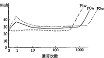
Because what shine laser beam on the CD-RW can be according to separately fabricator or type separately and different such as various setting the such as recording power, erase power, bottom power (bottom power), therefore, this optical disc recording system has shown following feature.Figure 1A and 1B show the relation between the shake of number of rewrites and CD-RW and the curve map of the wobble variation with different recording power re-write optical disk the time respectively.In this case, Figure 1A and 1B show with different recording power data are rewritten to situation on the same type CD-RW continuously.The amplitude of recording power is made as P2w<P0w<P1w, and P0w is an optimal recording power.
(1) recording power of response illuminating laser beam, CD-RW have the different jitter value when reproducing and rewrite can carry out number of times.In other words, shown in Figure 1A, under situation about CD-RW being write down with optimal recording power P0w, initial shake worsens, yet this shake improves gradually along with the increase of number of rewrites.Then, after having carried out about 10 rewritings, this shake is stable subsequently, but surpasses after 1000 times in number of rewrites, and shake worsens suddenly.As a result, under the situation with optimal recording power P0w record CD-RW, the user can rewrite 1000 times, this be orange paper (Orange Book) but the defined number of rewrites of third part.
Writing down under the situation of CD-RW with the recording power P1w that is better than optimal recording power P0w, even when number of rewrites is also very little, to shake also very stable and not deterioration, and differ widely with optimal recording power P0w, shake is improving all the time.Yet in number of rewrites during less than 1000 times, CD is aging to quicken and shake worsens suddenly.As a result, owing to shortened the life-span of CD-RW under the situation with recording power P1w record CD-RW, the user can only rewrite with 1000 times and compare quite little number of times.
On the contrary, under situation with the recording power P2w record CD-RW that is weaker than optimal recording power P0w, shown to optimal recording power P0w situation under similar feature, yet jitter value at this moment is poorer than the situation of optimal recording power P0w all the time.When carry out to rewrite 1000 times or more times the time, the aging slack-off and shake of CD worsens.As a result, owing to prolonged the life-span of CD-RW under the situation with recording power P2w record CD-RW, the user can rewrite above 1000 times.
(2) with certain recording power with data recording on CD-RW, under the situation with different recording power overwriting data, shake changes then.In other words, shown in Figure 1B, shine under the laser beam recording power situation of CD in the setting that concerns according to P2w<P0w<P1w, when with recording power P2w with data recording on CD-RW, then with recording power P0w (>P2w) during overwriting data, shake is improved.When with recording power P0w with data recording on CD-RW, when rewriteeing with identical recordings power P 0w then, the shake do not change.On the contrary, when with recording power P1w with data recording on CD-RW, then with recording power P0w (<P1w) during overwriting data, shake worsens.
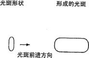
(3) have under the situation of identical light spot shape at illuminating laser beam, when recording power strengthened, the width that is formed at the pit on the CD-RW broadened.Fig. 2 A to 2C shows the pit shape that is formed on the CD-RW.For example, shown in Fig. 2 A to 2C, shine under the situation of laser beam recording power of CD in the setting that concerns according to P2w<P0w<P1w, the width of pit increases along with the enhancing of recording power, and the width of each pit has the relation of W2<W0<W1.When the setting that concerns according to P2e<P0e<P1e shines under the situation of laser beam erase power of CD, erase area broadens along with the increase of erase power.
In the example shown in Fig. 2 A and the 2C,, can wipe the pit that forms by with recording power P2w illuminating laser beam well if the erase power of laser beam is made as P2e or bigger.That is, can wipe this pit with erase power P2e, P0e or P1e.If the erase power of laser beam is set to P0e or bigger, then can wipe the pit that forms by with recording power P0w illuminating laser beam well.That is, can wipe this pit with erase power P0e or P1e, and can not wipe such pit well, and its side end still keeps with erase power P2e.In addition, if the erase power of laser beam is made as P1e or bigger, can wipe the pit that forms by with recording power P1w illuminating laser beam well.That is, can wipe pit with erase power P1e, but with erase power P2e or P0e can not wipe this pit well and its side end still can keep.
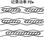
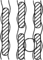
Therefore, rewriteeing under the situation of CD-RW, can produce following phenomenon by the optical disc recording system that is different from the optical disc recording system that is used for writing down legacy data.Fig. 3 A and 3B show the image views of the situation when rewriteeing CD-RW.Promptly, as shown in Figure 3A, writing down CD-RW with recording power P2w, then by with erase power P0e and recording power P0w (>P2w) illuminating laser beam comes under the situation of overwriting data, can wipe the original pit that forms by with recording power P2w illuminating laser beam well by the laser beam of erase power P0e.Therefore, the pit that forms with recording power P2w does not keep at all.When pit when forming with recording power P0w illuminating laser beam, shown in Figure 1B, when with recording power P0w illuminating laser beam, the situation of shake is fine.Therefore, shake improves and error rate reduces.
On the contrary, shown in Fig. 3 B, writing down CD-RW with recording power P1w, then by with erase power P0e and recording power be P0w (<P1w) illuminating laser beam rewrites under the situation of CD-RW, by can not wiping well with erase power P0e illuminating laser beam by being the original pit that the P1w illuminating laser beam forms with recording power, and its side end still keeps.This is because the laser beam of erase power P0e has narrower erase area.Owing to have narrower width than by the pit that forms with recording power P1w illuminating laser beam, so formed at the side end of original pit and newly formed lap between the pit by the pit that forms with recording power P0w illuminating laser beam.As a result, shake takes place to worsen and the error rate increase.
The optical disc recording system of certain manufacturer or types of models has the tactful setting of writing of himself.Fig. 4 is the example of writing strategy of this CD-RW.In addition, usually, write the laser power that strategy can be controlled CD-RW by setting.In this case, when the change firmware
(firmware) during form, change simultaneously and write power P w, erase power Pe and bottom power Pb, perhaps change wherein any one.In this mode, write among power P w, erase power Pe and the bottom power Pb at least any one if changed, even then in same optical disc recording system, can not finely wipe previous recorded data, and the end portion of pit keeps still.Therefore, shake takes place to worsen and the error rate increase.
The light spot shape that shines the laser beam of CD in the optical disc recording system has nothing in common with each other according to the fabricator separately of optical disc recording system.Fig. 5 A shows from the light spot shape of the laser beam of optical disc recording system and is formed at pit shape on the CD-RW to 5D.Shown in Fig. 5 A to 5D, in CD-RW is under the situation of CD-RW, in the system that A company, B company and C company make, the light spot shape of this optical disc recording system is set to along the laterally long ellipse of hot spot working direction, vertical longer ellipse and vergence direction long oval respectively.In CD-RW is under the situation of DVD-RW, DVD+RW or DVD-RAM, has presented circle, vertical ellipse, horizontal ellipse and the inclined ellipse light spot shape as its optical disc recording system.
Under this trend, shown in Fig. 5 A to 5D, because the light spot shape difference of laser beam, be formed at pit shape (width) on the CD-RW according to each fabricator of optical disc recording system and difference.Therefore, by another fabricator's optical disc recording system with data rewrite thereon the optical disc recording system by certain manufacturer write down under the situation on the CD-RW of data, even recording power is set to identical value with erase power respectively, still can occur with reference to the described identical phenomenon of figure 3B.In other words, the laser beam that has light spot shape shown in Fig. 5 A by irradiation with data recording on CD-RW D, have under the situation of laser beam overwriting data of light spot shape shown in Fig. 5 B by irradiation then, the end of original pit is not wiped free of and still keeps.Therefore, shake worsens, and error rate increases.On the contrary, the laser beam that has light spot shape shown in Fig. 5 B by irradiation with data recording on CD-RW D, the laser beam that has a light spot shape shown in Fig. 5 A by irradiation is come under the situation of overwriting data then, can wipe original pit well.Therefore, shake improves and has reduced error rate.
In this optical disc recording system, usually, after writing speed changes, can form pit, and when overwriting data, recording power and erase power are set, so that wipe original data well with same widths (shape).Yet, when writing speed not simultaneously because the changes in material of CD-RW or laser diode, therefore the width (shape) of the pit that forms can dissimilate.For this reason, in some cases, when overwriting data, the pit that forms before can not wiping well.For example, when data being rewritten on it with four times of speed records on the CD-RW of data with standard speed, then can not wipe pit well, thereby shake sometimes can take place to worsen and error rate increases with four times of speed records.
As mentioned above, in the optical disc recording system of prior art, shine laser beam on the CD-RW such as recording power, erase power, bottom power, writing record conditions such as strategy and light spot shape can be according to fabricator, types of models, form of firmware, writing speed etc. and different.According to record condition, CD-RW has different recording features.Therefore, under the situation of the CD-RW that data rewrite has been write down data thereon by certain optical disc recording system by another optical disc recording system, can not wipe the pit that forms on the CD-RW well, can not form new pit and cover original pit.As a result, shake takes place to worsen and the error rate increase.
Summary of the invention
Therefore, the purpose of this invention is to provide a kind of compact disk recording method and a kind of optical disc recording system, even when the CD-RW that rewrites by another optical disc recording system by certain optical disc recording system record, can record data and shake is worsened and can access lower error rate.
In order to overcome the problems referred to above, the present invention has following structure.
(1) a kind of compact disk recording method comprises step:
Be recorded in legacy data on the CD-RW by reproduction, obtain to be recorded in the reproducing signal of the legacy data on the CD-RW;
Can wipe the regenerative recording condition of legacy data well according to the reproducing signal setting of legacy data; And
According to determined regenerative recording condition new data is rewritten on the legacy data.
(2) according to the compact disk recording method of (1), wherein, when the user assigns to be provided with the recording operation of data and determines set recording operation for rewriting by operating portion, obtain the record condition of legacy data.
(3) a kind of compact disk recording method comprises step:
Detect amount of crosstalk the reproducing signal of the legacy data on being recorded in CD-RW;
Can wipe the record condition of legacy data well according to detected amount of crosstalk setting; And
Rewrite new data according to record condition.
(4), wherein, when the user assigns to be provided with the recording operation of data and determines set recording operation for rewriting by operating portion, detect amount of crosstalk according to (3) described compact disk recording method.
(5) according to (3) described compact disk recording method, wherein, respond detected amount of crosstalk and, record condition is set with reference to the difference between the amount of crosstalk.
(6), wherein, by writing the zone and determine optimal recording power, and detect with reference to amount of crosstalk according to the reproducing signal of the data that write down with optimal recording power with attempting writing the trial that is applied on the CD-RW according to (5) described compact disk recording method.
(7) a kind of compact disk recording method comprises step:
Obtain the peak to peak value of the legacy data reproducing signal that is recorded on the CD-RW;
The record condition that can wipe legacy data well is set according to the peak to peak value of being obtained; And
Rewrite new data according to record condition.
(8), wherein, when the user assigns to be provided with the recording operation of data and determines set recording operation for rewriting by operating portion, obtain described peak to peak value according to (7) described compact disk recording method.
(9) according to (7) described compact disk recording method, wherein, by writing and determine optimal recording power on the zone attempting writing the trial that is applied on the CD-RW, and response is provided with record condition with the difference between the peak to peak value of the reproducing signal of the peak to peak value of the reproducing signal of the data of optimal recording power record and legacy data.
(10) a kind of compact disk recording method comprises step:
Shining when the trial of CD-RW writes the laser power in zone, use described trial and write with the scheduled volume change;
The reproducing signal that writes data according to trial is determined optimal recording power;
Peak value and valley according to the reproducing signal of the data of optimal recording power record obtain first peak to peak value;
According to the peak value and the valley of the reproducing signal that is recorded in the legacy data on the CD-RW, obtain the second peak to peak value; And
Respond the difference between the described first and second peak to peak values, proofread and correct the erase power that shines laser beam on the CD-RW, and rewrite new data by the erase power of using after proofreading and correct.
(11), wherein, when the user assigns to be provided with the recording operation of data and determines set recording operation for rewriting by operating portion, use described trial and write according to (10) described compact disk recording method.
(12) a kind of optical disc recording system comprises:
Reproduction units is used to reproduce the data that are recorded on the CD-RW;
The crosstalk detection unit is used for detecting amount of crosstalk from the reproducing signal of reproduction units;
Record condition is provided with the unit, is used for basis by the detected amount of crosstalk in crosstalk detection unit, and setting can be wiped the record condition of legacy data well; And
Record cell is used for according to by record condition the set record condition in unit being set new data being rewritten on original data.
(13) a kind of optical disc recording system comprises:
Reproduction units is used to reproduce the data that are recorded on the CD-RW;
The envelope detected unit is used to obtain the peak to peak value of the reproducing signal of reproduction units;
Record condition is provided with the unit, is used for the peak to peak value obtained according to the envelope detected unit, and setting can be wiped the record condition of legacy data well; And
Record cell is used for according to record condition the set record condition in unit being set, and new data is rewritten on original data.
Description of drawings
Figure 1A and 1B show the relation between the shake of number of rewrites and CD-RW respectively and the curve map of the variation of shaking with different recording power re-write optical disk the time.
Fig. 2 A to 2C shows the view that is formed at the pit shape on the CD-RW.
Fig. 3 A and 3B show the image views of the situation when rewriteeing CD-RW.
Fig. 4 is the example of writing strategy of CD-RW.
Fig. 5 A to 5D shows from the light spot shape of the laser beam of optical disc recording system and is formed at pit shape on the CD-RW.
Fig. 6 shows the block diagram according to the optical disc recording system structure of the embodiment of the invention.
Fig. 7 shows the sectional view of the regional structure of CD.
Fig. 8 A and 8B show posting field and reproduce the synoptic diagram that concerns between the hot spot.
Fig. 9 shows the block scheme of crosstalk detection circuit details.
Figure 10 A and 10B are the signal of output when light picker moves and the oscillogram of amount of crosstalk definition.
Figure 11 is in the optical disc recording system according to first embodiment, and the process flow diagram of the operation that detects amount of crosstalk is described.
Figure 12 A to 12C shows the figure with the reproduction waveform of the pit of different recording power trace and each pit.
Figure 13 A to 13C is the pattern of reproducing signal, has wherein reproduced the pit 3T to 11T that writes down under condition shown in Figure 12 A.
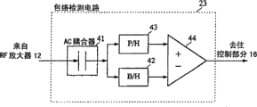
Figure 14 shows the block scheme of envelope detected circuit details.
Figure 15 is in the optical disc recording system according to second embodiment, and the process flow diagram of the operation that detects the PP value is described.
Embodiment
Below to data rewrite to describing as the situation on the CD-RW of the example of CD-RW.At first, will the details according to the optical disc recording system of the embodiment of the invention be described.Fig. 6 shows the block diagram according to the optical disc recording system structure of the embodiment of the invention.In the present embodiment, this structure shows and uses laser beam as the light beam that shines on the CD.As described in Figure 6, optical disc recording system 1 comprises light picker 10, spindle drive motor 11, RF amplifier 12, servo circuit 13, ATIP testing circuit 14, demoder 15, control section 16, scrambler 17, strategy circuit 18, laser driver 19, laser power control circuit 20, frequency generator 21, crosstalk detection circuit 22, envelope detected circuit 23, reproduced signal quality testing circuit 24, storage area 25, operation part 27 and display part 28.Constitute recording section 29 by light picker 10, servo circuit 13, scrambler 17, strategy circuit 18, laser driver 19 and laser power control circuit 20 as data record unit.In addition, constitute reproducing part 30 by light picker 10 and RF amplifier 12 as the data reproduction unit.
Spindle drive motor 11 is the motor that are used to rotate/drive as the CD D of data recording target.Be provided for fixing the CD-fixing device (not shown) such as panoramic table of (clamping) CD to the head portion of the turning axle of spindle drive motor.
Frequency generator 21 detects from the rotation angle or the rotation number of spindle drive motor 11 outputs, then this signal is outputed to servo circuit 13.
The EFM modulated rf signal that is provided by light picker 10 is provided the RF amplifier, then the RF signal that amplifies is outputed to reproduced signal quality testing circuit 24 and demoder 15 that servo circuit 13, ATIP detect electric current 14, crosstalk detection circuit 22, envelope detected circuit 23, are used to measure reproduced signal quality.
In reproducing operation, the RF signal after the EFM that demoder 15EFM demodulation is provided by RF amplifier 12 modulates outputs to storage area 25 with these data then to produce the data of reproducing.In recording operation, demoder 15 carries out the EFM demodulation reproducing wherein when having write down data regional by test record to the RF signal that is provided by RF amplifier 12.
In optical disc recording system 1, when record data, before carrying out the normal data record, test record is applied to PCA (power calibration area) zone of the inner circumferential side of CD D according to present embodiment.Then, according to the reproduction result in this test record zone, produce the record condition that allows to record preferably on the CD.
Now, the zone of wherein having used the CD D of test record with reference to 7 couples in figure describes.Fig. 7 shows the synoptic diagram of disc area structure.The overall diameter of this CD D is 120mm.Partly prepare as ingress area 114 along the diametric 46mm to 50mm of CD D, and prepared to be used for the program zone 118 and the reserve area 120 of record data in the outer circumferential sides of ingress area 114.On the contrary, prepared inner circumferential side PCA zone 112 in the inner circumferential side of ingress area 114.Test zone 112a and counting region 112b have been prepared in the inner circumferential side in PCA zone 112.As mentioned above, before normal recordings, test record is applied to test zone 112a.Here, prepare repeatedly the zone of application testing record, as test zone 112a.To be illustrated in EFM signal record which that record test zone 112a when test record finishes partly be done on the 112b of counting region.Therefore, when test record being applied to this CD D next time,, can knowing and to begin this test record from which position of test zone 112a by detecting the EFM signal in the 112b of counting region.In the optical disc recording system 1 of present embodiment, before carrying out normal data recording, test record is applied among the above-mentioned test zone 112a.
Return Fig. 6, storage area 25 has been stored from the reproduction data of the CD D of demoder 15 output, from the data of the outside input of optical disc recording system 1 etc.Then, when playing, the data of storage are outputed to data reproduction part (not shown), and when data recording to recording disk the time, is outputed to scrambler 17 with the data of being stored.
For before test record is applied to CD D, detection should from the test zone 112a of CD D which partly, envelope detected circuit 23 detects the envelope of the EFM signal among the above-mentioned counting region 112b of CD D.
When reproducing the test record zone of CD D, reproduced signal quality testing circuit 24 is according to the RF signal that is provided by RF amplifier 12, calculate β value and the asymmetry relevant with reproduced signal quality, the result that will calculate outputs to control section 16 then.Can be by β=(a+b)/(a-b) calculate β value, wherein a is the peak level (symbol be+) through the signal waveform of EFM modulation, and b is a valley level (symbol is) wherein.
Servo circuit 13 is carried out the Spin Control of spindle drive motor 11 and focus control, tracking Control and the feeding control of light picker 10.In optical disc recording system 1 according to present embodiment, can switch between CAV (Constant Angular Velocity) system and CLV (constant linear velocity) system when writing down, wherein CAV and CLV are respectively as the system that drives CD D with Constant Angular Velocity with drive the system of CD D with constant linear velocity.Therefore, the control signal that servo circuit 13 responses are provided by control section 16 is switched CAV system and CLV system.Now, in the CAV control of being undertaken by servo circuit 13, controlled rotation number, made it consistent with the rotation number that is provided with by frequency generator 21 detected spindle drive motors 11.In CLV that servo circuit 13 carries out control, control spindle drive motor 11, thus the swinging signal in the RF signal that is provided by RF amplifier 12 is set to the multiple of speed.
17 pairs of record data that provided by storage area 25 of scrambler carry out the EFM modulation, then these data are outputed to strategy circuit 18.Strategy circuit 18 is applied to the EFM signal that provided by scrambler 17 with time base correction processing etc., then consequential signal is outputed to laser driver 19.The record data that laser driver 19 response is provided by strategy circuit 18 and the control of laser power control circuit 20 drive laser diode in the light picker 10 according to the signal of modulation.
Laser power control circuit 20 controls are by the laser power of the irradiation of the laser diode in the light picker 10.More specifically, laser power control circuit 20 is according to should be according to current value that is provided by monitoring diode in the light picker 10 and the information that is used to indicate the optimal laser power desired value that is provided by control section 16, from light picker 10, irradiate the mode of laser beam, control laser driver 19 with optimal laser power.
The reference amount of crosstalk CT0 of the CD-RW of storage area 25 each types of models of storage.Setting operation part 27 is to carry out the operation of data recording to the CD.Display part 28 is set to show such as the content by operation part 27 content of operation that carry out, that should send the user to.
First embodiment
To the optical disc recording system according to first embodiment of the invention be described below.Fig. 8 A and 8B show posting field and reproduce the synoptic diagram that concerns between the hot spot, wherein Fig. 8 A shows with the zone of optimal recording power record and reproduces relation between the hot spot, and Fig. 8 B shows with the zone of the power trace that is higher than optimal recording power and reproduces relation between the hot spot.Shown in Fig. 8 A, when with the best power record data, suitably formed pit (by with laser beam irradiation on CD-RW, make recording layer be in amorphous part) width.Therefore, because the influence that pit is caused when hot spot is positioned at level land (land) is very little, so the minimizing of catoptrical signal level is also less.Coming with optimal recording power in this manner under the situation of record data, in the reproduction process of a certain track, other track exert one's influence hardly (amount of crosstalk).On the contrary, shown in Fig. 8 B, when when being higher than the power trace data of best power, the width thickening of pit.Therefore, because pit is big to the influence change of hot spot when hot spot is positioned at the level land, so catoptrical signal level further reduces.In this manner, in this CD-RW, the width of pit dissimilates according to recording power, and amount of crosstalk is also correspondingly different.
Therefore, in optical disc recording system according to first embodiment of the invention, be stored in the amount of crosstalk of the optimal recording power place generation of this CD-RW in advance, then when will be with data rewrite on this CD-RW the time, be recorded in data on the CD-RW by reproduction and detect amount of crosstalk in this reproducing signal, then with this amount of crosstalk with compare with reference to amount of crosstalk.As mentioned above, because amount of crosstalk is characterised in that amount of crosstalk along with the pit width thickening, promptly strengthens and increase along with recording power, therefore, it is feasible coming the detection record performance number by mutual relatively amount of crosstalk.In optical disc recording system according to first embodiment of the invention, use this feature that the amount of crosstalk of two data is compared mutually, response ratio result then, record condition change such as erase power, the recording power etc. (for example, with these condition changings is identical with the record condition of the optical disc recording system that writes down legacy data) so that overwriting data.As a result, when coming overwriting data, can wipe original data well, thereby can prevent the deterioration of shaking and can reduce error rate by the optical disc recording system that is different from the optical disc recording system that writes down legacy data.
Because record condition changes according to the comparative result of amount of crosstalk, when with data rewrite on CD-RW the time, can change optical disc recording system and shine laser beam erase power on this CD-RW, will be thereby can unsuccessfully not wipe through the legacy data that rewrites.By changing such as the recording power, bottom power (bias power), the ε (erase power/recording power) that obtain by OPC etc., writing conditions such as strategy, recording power corrected value, can rewrite (wipe and write down) data as the original disc register system.
In this case, be weaker than at the recording power of the optical disc recording system that is used to write down legacy data under the situation of recording power of the optical disc recording system that is used for overwriting data etc., must increase erase power and recording power.Therefore, accelerated the aging of laser diode in CD-RW and the optical disc recording system 1.Therefore, in this case, when with data rewrite on CD-RW the time, can respond the crossfire value of legacy data, increase the erase power that shines the laser beam on the CD-RW, can use then in optical disc recording system as the value of himself initial value setting and come overwriting data, and need not to change recording power.Therefore, can suppress the aging of laser diode in CD-RW and the optical disc recording system 1.
Be better than at the recording power of the optical disc recording system that is used for overwriting data under the situation of recording power of the optical disc recording system that is used to write down legacy data etc., can data be rewritten with its initial erase power and recording power, and do not change initial value
Fig. 9 shows the block scheme of crosstalk detection circuit details.Figure 10 A and 10B are that light picker moves the signal of time output and the oscillogram of amount of crosstalk definition.In optical disc recording system 1, as mentioned above, detect crossfire value by crosstalk detection circuit 22.As shown in Figure 9, this crosstalk detection circuit 22 is made of low-pass filter (LPF) 31, valley hold circuit (B/H) 32, peak holding circuit (P/H) 33 and counting circuit 34.
Low-pass filter 31 ends the radio-frequency component of output signal in the RF amplifier 12, and low frequency component is outputed to valley hold circuit 32 and peak holding circuit 33.Valley hold circuit 32 keeps the valley A of the signal of output from low-pass filter 31 and with its output.Peak holding circuit 33 keeps from the peak value B of the signal of low-pass filter 31 outputs and with its output.Counting circuit 34 reaches from the peak value B executable operations of peak holding circuit 33 outputs by using from the valley A of valley hold circuit 32 outputs, thereby calculates amount of crosstalk.
At crosstalk detection circuit 22, carry out the processing of the following stated.Shown in Figure 10 A, when when at rotary CD the time, having moved light picker, from RF amplifier 12 output signal I.Signal I be its level therein reflection coefficient with respect to the signal that reduces in the lower pit portion of mirror image level.Pit (EFM) is a kind of high-frequency signal.The valley level of pit on the level land or the repetition period of groove place be increased or dwindle, and the increase of level/reduce to appear on its peak signal with the predetermined cycle.The envelope that solid line is represented among Figure 10 A has provided the envelope that obtains when reproducing the part that writes down with optimal recording power, and the envelope that dotted line is represented among Figure 10 A has provided the envelope that obtains when reproducing the part that writes down with high power.
By after the low-pass filter 31, the signal I of RF amplifier 12 outputs becomes signal II shown in Figure 9 at signal.Signal II is the low envelope signal of signal I, and is in minimum level in groove, is in maximum level on the level land.Valley hold circuit 32 will carry out valley from the minimum level of the signal II of low-pass filter 31 output and remain the A level and obtain this level.Peak holding circuit 33 carries out peak value with the maximum level of the signal II of low-pass filter 31 output and remains the B level and obtain this level.Counting circuit 34 utilizes from the valley A of valley hold circuit 32 outputs and reaches the peak value B execution computing B/A that exports from peak holding circuit 33, so that calculate levels of crosstalk.
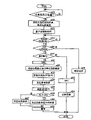
In optical disc recording system 1, carry out processing as described below in case with data rewrite on CD-RW.Figure 11 is the process flow diagram that is used for illustrating detect the operation of amount of crosstalk according to the optical disc recording system of first embodiment.
At first, with data recording under the situation on the CD-RW, the user is positioned over CD-RW on the pan arrest of optical disc recording system 1.The control section 16 of optical disc recording system detects CD (s1) is set, clamps this CD-RW then, afterwards, light picker is moved on the precalculated position, and obtains the initial information (s2) of CD by illuminating laser beam.More specifically, at first control section 16 is determined the type of the reflectivity of laser beam with the identification CD.At this moment,, can determine that then this CD is CD-RW (CD-RW) if the reflectivity of CD is lower, and if if the reflectivity of CD is higher, then this CD is CD-WORM (CD-R) or read-only (can not write down) CD (CD-ROM).Control section 16 detects in the ingress area that is arranged on CD in the optical disc recording system 1 whether have the swing composition, and when having swing information, detects atip information.If detect atip information, then CD is defined as can rewriteeing or CD-WORM, in each control, use then be contained in the atip information such as dish ID (maker code), STLT information such as (start times of Lead-In Area: be equal to maker code and dish code).In this manner, control section 16 is according to reflectivity and atip information, determines corresponding to rewriteeing, write once and in the read-only optical disc which.Control section 16 obtains the dish ID of CD from atip information.
Then, control section 16 shows the content (s3) that is used to inquire the processing that is applied to the CD-RW that is provided with by the user on display part 28.The user responds this demonstration, and input will be applied to the processing of set CD-RW.If control section 16 detects from the input of operation part 27 (s4), and if be provided with data reproduction (s5), then this control section 16 is carried out data reproduction processes (s6).When data reproduction was finished, control section 16 finished this processing.
On the contrary, if be provided with data recording (s5), control section 16 determines that this recording operation is original records or rewriting (s7).More specifically, control section 16 determines whether there is the EFM signal in Lead-In Area and PMA, then, if do not write down the EFM signal in these two zones or guiding area, then this recording operation is defined as original records.Be blank disc or be under the situation in the recording process, when the first time, at CD-RW the not recording areas of data recording in CD D.Therefore, control section 16 is determined optimal recording power (s8) by carrying out the OPC among the PCA.Then, control section 16 is in CD-RW identifying recording layer or write-once data (s9), end process then.
On the contrary, at step s7, if the EFM signal record in the Lead-In Area or PMA of CD-RW, then control section 16 is determined to carry out rewriting, reproduces the legacy data (s11) that is recorded on this CD-RW then.If control section 16 has obtained to be recorded in the amount of crosstalk CT1 (s12) of the data on the CD-RW from crosstalk detection circuit 22, then this control section 16 reads from storage area 25 with reference to amount of crosstalk CT0 (S13).Then, control section 16 calculates CT1-CT0 (s14).If result calculated has surpassed 0, then control section 16 changes record condition.For example, control section 16 by multiplying each other and carry out correction with reference to erase power P0e and reference record power P 0w and CT1/CT0 and predetermined enumerate (enumeration), these corrected values (s16) are set then then, control section 16 with the erase power after proofreading and correct and the recording power after proofreading and correct with data rewrite (s18) on CD-RW, and when record is finished, finish this processing.
On the contrary, if the result of calculation of CT1-CT0 less than 0 (s15), then control section 16 record conditions are set to initial value set in this optical disc recording system 1.In other words, control section 16 erase powers and recording power are set to data rewrite (s18) on CD-RW, when data recording is finished, finish this processing then then with reference to erase power P0e and reference record power P 0w (s17).
Here, as mentioned above, can will be recorded in storage area 25 with reference to amount of crosstalk CT0 at the CD-RW of each types of models.Can as described belowly calculate this with reference to amount of crosstalk CT0.That is, when the optical disc recording system overwriting data, determine optimal recording power by carrying out OPC, reproduce the test data with this optimal recording power record then, so that calculate the value of amount of crosstalk, this value is set to reference to amount of crosstalk then.Then, as mentioned above, can be recorded in the amount of crosstalk CT1 that legacy data on the CD-RW detects data, can respond the difference of CT1-CT0 then, determine record condition by reproduction.If do like this, can increase the required time of record condition of determining slightly, yet, even this CD-RW is the CD of newly selling, also can determines the best titime condition of this CD-RW rapidly and need not to upgrade firmware etc.Second embodiment
Next, will the optical disc recording system according to second embodiment of the invention be described.Figure 12 A to 12C is the view with the reproduction waveform of the pit of different recording power trace and each pit.In Figure 12 A, pit a is the pit that writes down with the recording power that is higher than optimal recording power by by the strategy shorter than optimal strategy.Pit b is by the pit of optimal strategy with the optimal recording power record.Pit c is the pit that writes down with the recording power that is lower than optimal recording power by the strategy longer than optimal strategy.Shown in Figure 12 A, the width of pit a, pit b and pit c has the relation of Wa>Wb>Wc, and the length of pit a, pit b and pit c has the relation of La<Lb<Lc.Shown in Figure 12 B, when reproducing each pit, along with the thickening of pit width, the peak to peak value of the reproducing signal of the such generation relevant with reproducing beam spot size (below be referred to as " PP value ") increases greatly more.Yet shown in Figure 12 C, when to each reproducing signal binary coding, they all provide identical signal.
Figure 13 A to 13C is the pattern of reproducing signal, has wherein reproduced the pit 3T to 11T that writes down under condition shown in Figure 12 A.Hereinafter the pattern with this reproducing signal is called " eye pattern ".Figure 13 A shows by than the eye pattern of the short strategy of optimal strategy with the reproducing signal of the pit of the recording power record that is higher than optimal recording power.Figure 13 B shows by optimal strategy, with the eye pattern of the reproducing signal of the pit of optimal recording power record.Figure 13 C shows by than the eye pattern of the long strategy of optimal strategy with the reproducing signal of the pit of the recording power record that is lower than optimal recording power.Shown in Figure 13 A to 13C, be understandable that when when center wavy line (waveline) is cut apart these eye patterns, these reproducing signals all equate under all conditions, still,, become greatly as the PP value of eye pattern opening along with recording power increases.That is, the relation between the PP value of each eye pattern shown in Figure 13 A to 13C is given PPa>PPb>PPc.
Therefore, in optical disc recording system,, calculate PP value then with the data of optimal recording power record when data rewrite on CD-RW the time, by OPC is applied to CD-RW, is detected optimal recording power according to second embodiment of the invention.The original data that will be rewritten that are recorded on the CD-RW by reproduction detect the PP value, then the PP value of this PP value with the data that write down with optimal recording power are compared.As mentioned above, increase greatly along with recording power becomes owing to the PP value is characterised in that this PP value, therefore the comparison of this PP value can the detection record performance number.In optical disc recording system according to second embodiment of the invention, by using this feature that the PP value (opening of eye pattern) of two data is compared mutually, response ratio is result such as record conditions such as erase power, recording powers (for example change, record condition is changed into the identical record condition of record condition with the optical disc recording system that has write down legacy data by it) so that overwriting data.As a result, owing to when utilizing the optical disc recording system different to come overwriting data, can wipe legacy data well, therefore can avoid the deterioration of shaking and can reduce error rate with the optical disc recording system that has write down legacy data by it.
Because the comparative result according to amount of crosstalk changes record condition, when with data rewrite on CD-RW the time, the erase power that optical disc recording system shines the laser beam on the CD-RW can be changed, thereby the legacy data that is just being rewritten can be guaranteed to wipe.By changing such as the recording power, bottom power (bias power), the ε (erase power/recording power) that obtain by OPC, writing conditions such as strategy, recording power corrected value, can rewrite (wipe and write down) data as the original disc register system.
In this case, be weaker than at the recording power of the optical disc recording system that is used to write down legacy data under the situation of recording power of the optical disc recording system that is used for overwriting data etc., must increase erase power and recording power.So, accelerated the aging of laser diode in CD-RW and the optical disc recording system 1.Therefore, in this case, when with data rewrite on CD-RW the time, can respond the PP value of legacy data, increase the erase power of the laser beam that shines CD-RW, can use then in optical disc recording system as the value of himself initial value setting and come overwriting data, and not change recording power.As a result, can suppress the aging of laser diode in CD-RW and the optical disc recording system 1.
Figure 14 shows the block diagram of envelope detected circuit details.In optical disc recording system 1, detect the PP value of reproducing signal by envelope detected circuit 23.As shown in figure 14, this envelope detected circuit 23 is made up of AC coupling mechanism 41, valley hold circuit (B/H) 42, peak holding circuit (P/H) 43 and counting circuit (OP amplifier) 44.
In optical disc recording system 1, when overwriting data, check whether the recording power in the record condition of the pit write down data thereon is higher than optimal recording power.As illustrated with reference to figure 3A and 3B, this is because in some cases, if when rewriteeing record condition is not set suitably, then can not wipe legacy data fully.Therefore, in optical disc recording system 1, by light beam irradiates being obtained reproducing signal to the track record pit as the rewriting object with the reproducing power level.In envelope detected circuit 23, after the reproducing signal from 12 outputs of RF amplifier passes through AC coupling mechanism 41, keep valley by valley hold circuit 42, and keep peak value by peak holding circuit, then, calculate PP value (eye pattern opening signal) according to the difference between these values, and output to control section 16.
Can obtain the PP value that has write down the posting field of data thereon with optimal recording power constantly at OPC, perhaps can obtain this value on another opportunity.Control section 16 is determined that the opening of which eyelet pattern is bigger, and is responded this difference according to the difference between two PP values, makes erase power the best.If bigger, then carry out control to increase erase power as the eye pattern in the zone that rewrites object.
Next, with explanation when according to the applied processing on CD-RW the time of the optical disc recording system of second embodiment of the invention with data rewrite.Figure 15 is explanation is used to detect the operation of PP value in the optical disc recording system according to second embodiment a process flow diagram.
As shown in figure 15, at first, with data recording under the situation on the CD-RW, the user places CD-RW on the pan arrest of optical disc recording system 1.The control section 16 of optical disc recording system 1 detects CD (s21) is set, clamps this CD-RW then, afterwards, light picker is moved on the precalculated position, and obtains the initial information (s22) of CD by illuminating laser beam.More specifically, at first, control section 16 is determined the reflectivity of laser beam, to discern the type of this CD.At this moment,, can determine that then this CD is CD-RW (CD-RW) if the reflectivity of CD is lower, and if if the reflectivity of CD is higher, then this CD is CD-WORM (CD-R) or read-only (can not write down) CD (CD-ROM).Whether there is the swing composition in the ingress area of control section 16 detections set CD in optical disc recording system 1,, detects atip information if there is swing information.If detect atip information, then CD is defined as can rewriteeing or CD-WORM, in each control, use then be contained in the atip information such as dish ID (maker code), STLI information such as (Lead-In Area start times: be equal to maker code and dish code).In this manner, control section 16 is according to reflectivity and atip information, determine CD corresponding to can rewriting, in write-once and the read-only optical disc which.Control section 16 obtains the dish ID of CD from atip information.
Then, control section 16 shows the content (s23) that is used to inquire the processing that is applied to the CD-RW that is provided with by the user on display part 28.The user responds this and shows that input will be applied to the processing of set CD-RW.If control section 16 detects from the input of operation part 27 (s24) and be provided with data reproduction (s25), then this control section 16 is carried out data reproduction processes (s26).When data reproduction was finished, control section 16 finished this processing.
On the contrary, if be provided with data recording (s25), control section 16 determines that this recording operation is original records or rewriting (s27).More specifically, control section 16 determines the EFM signal whether occurred in Lead-In Area and PMA, if then in two zones or do not write down the EFM signal in Lead-In Area, then this recording operation is defined as original records.Be blank disc or be under the situation in the recording process, when the first time, at CD-RW the not recording areas of data recording in CD D.Therefore, control section 16 is determined optimal recording power (s28) by carry out OPC in PCA.Then, control section 16 writes down these data or write-once data (s29) on CD-RW, finish this processing then.
On the contrary, at step s27, if the EFM signal record in the Lead-In Area or PMA of CD-RW, then control section 16 is determined to carry out rewriting, and at first determines optimal recording power (s31) by carrying out OPC.More specifically, by repeating the predetermined power increment, in the PCA of CD-RW, carry out trial and write with 15 power levels.Then, reproduce the data that trial writes, then reproducing signal is outputed to reproduced signal quality testing circuit 24, so that calculate the β value.Then, this β value approaches the power level in the zone of predetermined value most to select to be used to write down wherein, as the optimal recording power level.
Then, the data (s32) that the control section 16 of optical disc recording system 1 reproduces with the optimal recording power record obtain the PP value P0 by 23 outputs of envelope detected circuit then, and temporarily keep (storage) this value (s33).Control section 16 reproduces the legacy data (s34) that is recorded on the CD-RW, obtains the PP value P1 (s35) by 23 outputs of envelope detected circuit then.Then, control section 16 calculates the difference between PP value P0 and the PP value P1, and responds this difference and make erase power the best.Under the situation of P0-P1<0, control section 16 changes record condition.For example, because legacy data has bigger recording power, so control section 16 erase powers are set to the predetermined value (s37) greater than reference value.Then, control section 16 passes through the erase power after this correction of application, with data rewrite (s39) on CD-RW, afterwards, when data recording is finished, finishes this processing.
On the contrary, under the situation of P0-P1 〉=0, control section 16 record conditions are set to the initial value of setting in the optical disc recording system 1.That is, control section 16 erase powers and recording power are set to reference to erase power P0e and reference record power P 0w (s38), then with data rewrite (s39) on CD-RW, and when data recording is finished, finish this processing.
Utilizing foregoing, is that the situation of CD-RW is illustrated to recording medium.The present invention also can be applicable to DVD-RW and DVD+RW.
According to the present invention, can realize following advantages.
(1) according to be recorded in CD-RW on the consistent record of the reproducing signal of legacy data Condition rewrites data. Therefore, can wipe well legacy data, and can reproduce new rewriting Data and can not be subjected to the impact of legacy data.
(2) amount of crosstalk increases along with the enhancing that shines the recording power on the CD-RW, Thus, the width thickening of pit. Therefore, by amount of crosstalk relatively can infer be applied to original Recording powers of laser beam on the data.
(3) calculated and the reproducing signal of data on being recorded in CD-RW, detected Amount of crosstalk and with reference to the difference between the amount of crosstalk. Therefore, can grasp with respect to reference record Much power levels of power (optimal recording power) have recorded legacy data.
(4) by reproducing the test data with the optimal recording power record, from reproducing signal, examine Survey the value of amount of crosstalk, should be worth then and be used as with reference to amount of crosstalk. Therefore, even newly selling In the CD-RW, also can determine fast for the best titime condition of CD-RW and do not have Need to upgrade firmware etc.
(5) the peak to peak value of amplitude that is recorded in the data of CD-RW can weigh along with shining The enhancing of the recording power on the writing optical disk and increasing, thus, the width thickening of pit. Therefore, Can infer the recording powers of laser beam of legacy data according to the peak to peak value of reproducing signal amplitude.
(6) come the peak of detected amplitude to arrive by the legacy data of reproducing on CD-RW Peak value, and with the peak-to-peak value of this amplitude and peak to peak with optimal power recorded data amplitude Value compares. Therefore, can infer the recording powers of laser beam of legacy data.
(7) peak of the reproducing signal by the legacy data of detection record on CD-RW arrives Peak value and with the difference between the peak to peak value of the data of optimum recording power record can detect Legacy data and will rewrite the difference of record condition between the data. Therefore, if respond this difference Proofread and correct erase power, then can wipe well original data, and in optimum recording conditions The data that lower record will rewrite.
Claims (11)
1. compact disk recording method comprises:
Detect amount of crosstalk the reproducing signal of the legacy data on being recorded in CD-RW;
Can wipe the record condition of legacy data well according to detected amount of crosstalk setting; And
Rewrite new data according to record condition.
2. compact disk recording method according to claim 1 is characterized in that: when the user assigns to be provided with the recording operation of data and determines set recording operation for rewriting by operating portion, detect amount of crosstalk.
3. compact disk recording method according to claim 1 is characterized in that: respond detected amount of crosstalk and with reference to the difference between the amount of crosstalk, record condition is set.
4. compact disk recording method according to claim 3, it is characterized in that by writing the zone and determine optimal recording power, and detect with reference to amount of crosstalk according to the reproducing signal of the data that write down with optimal recording power with attempting writing the trial that is applied on the CD-RW.
5. compact disk recording method comprises:
Obtain the peak to peak value of the legacy data reproducing signal that is recorded on the CD-RW;
The record condition that can wipe legacy data well is set according to the peak to peak value of being obtained; And
Rewrite new data according to record condition.
6. compact disk recording method according to claim 5 is characterized in that obtaining described peak to peak value when the user assigns to be provided with the recording operation of data and determines set recording operation for rewriting by operating portion.
7. compact disk recording method according to claim 5, it is characterized in that by writing and determine optimal recording power on the zone, and response is provided with record condition with the difference between the peak to peak value of the reproducing signal of the peak to peak value of the reproducing signal of the data of optimal recording power record and legacy data attempting writing the trial that is applied on the CD-RW.
8. compact disk recording method comprises:
Shining when the trial of CD-RW writes the laser power in zone with the scheduled volume change, using and attempt writing;
The reproducing signal that writes data according to trial is determined optimal recording power;
Peak value and valley according to the reproducing signal of the data of optimal recording power record obtain first peak to peak value;
According to the peak value and the valley of the reproducing signal that is recorded in the legacy data on the CD-RW, obtain the second peak to peak value; And
Respond the difference between the described first and second peak to peak values, proofread and correct the erase power that shines laser beam on the CD-RW, and rewrite new data by the erase power of using after proofreading and correct.
9. compact disk recording method according to claim 8 is characterized in that using described trial and writing when the user assigns to be provided with the recording operation of data and determines set recording operation for rewriting by operating portion.
10. optical disc recording system comprises:
Reproduction units is used to reproduce the data that are recorded on the CD-RW;
The crosstalk detection unit is used for detecting amount of crosstalk from the reproducing signal of reproduction units;
Record condition is provided with the unit, is used for basis by the detected amount of crosstalk in crosstalk detection unit, and setting can be wiped the record condition of legacy data well; And
Record cell is used for according to by record condition the set record condition in unit being set new data being rewritten on original data.
11. an optical disc recording system comprises:
Reproduction units is used to reproduce the data that are recorded on the CD-RW;
The envelope detected unit is used to obtain the peak to peak value of the reproducing signal of reproduction units;
Record condition is provided with the unit, is used for the peak to peak value obtained according to the envelope detected unit, and setting can be wiped the record condition of legacy data well; And
Record cell is used for according to record condition the set record condition in unit being set, and new data is rewritten on original data.
Applications Claiming Priority (3)
| Application Number | Priority Date | Filing Date | Title |
|---|---|---|---|
| JP2003065709 | 2003-03-11 | ||
| JP2003065709A JP3938075B2 (en) | 2003-03-11 | 2003-03-11 | Optical disc recording method and optical disc recording apparatus |
| JP2003-065709 | 2003-03-11 |
Publications (2)
| Publication Number | Publication Date |
|---|---|
| CN1530938A CN1530938A (en) | 2004-09-22 |
| CN100429707C true CN100429707C (en) | 2008-10-29 |
Family
ID=33126652
Family Applications (1)
| Application Number | Title | Priority Date | Filing Date |
|---|---|---|---|
| CNB2004100284419A Expired - Fee Related CN100429707C (en) | 2003-03-11 | 2004-03-11 | Disc recording method and system |
Country Status (3)
| Country | Link |
|---|---|
| US (1) | US20040257932A1 (en) |
| JP (1) | JP3938075B2 (en) |
| CN (1) | CN100429707C (en) |
Families Citing this family (5)
| Publication number | Priority date | Publication date | Assignee | Title |
|---|---|---|---|---|
| KR101027402B1 (en) * | 2004-11-16 | 2011-04-11 | 주식회사 히타치엘지 데이터 스토리지 코리아 | Method for controlling servo for blank disk |
| JP4554441B2 (en) * | 2005-06-06 | 2010-09-29 | 富士通株式会社 | Magnetic disk device, preventive maintenance detection method thereof, and preventive maintenance detection program |
| US20070047411A1 (en) * | 2005-08-30 | 2007-03-01 | Manuel Rivera | Method and system for verifying media compliance |
| US8599663B1 (en) * | 2007-10-15 | 2013-12-03 | Marvell International Ltd. | High speed forward sense sampling in optical drives using placed data patterns |
| WO2013111382A1 (en) * | 2012-01-27 | 2013-08-01 | 日立コンシューマエレクトロニクス株式会社 | Optical disk device |
Citations (2)
| Publication number | Priority date | Publication date | Assignee | Title |
|---|---|---|---|---|
| JPH1040548A (en) * | 1996-07-26 | 1998-02-13 | Taiyo Yuden Co Ltd | Running opc method for optical disk and optical disk recording/reproducing apparatus |
| CN1250208A (en) * | 1998-09-28 | 2000-04-12 | 松下电器产业株式会社 | Optical information recording media and optical information recording apparatus and method for recording test signal on the same media |
Family Cites Families (13)
| Publication number | Priority date | Publication date | Assignee | Title |
|---|---|---|---|---|
| JP3124720B2 (en) * | 1995-04-14 | 2001-01-15 | 株式会社リコー | Information recording / reproducing method, information recording / reproducing device, and information recording medium |
| JPH03171437A (en) * | 1989-11-30 | 1991-07-24 | Matsushita Electric Ind Co Ltd | Signal recording method and optimum power setting device |
| EP0818783A3 (en) * | 1991-07-16 | 1999-04-14 | Canon Kabushiki Kaisha | Magneto optical recording medium and method |
| JP3359067B2 (en) * | 1991-11-15 | 2002-12-24 | キヤノン株式会社 | Magneto-optical recording method |
| US5485433A (en) * | 1991-12-19 | 1996-01-16 | Canon Kabushiki Kaisha | Information recording method and apparatus for determining whether recording has been correctly performed |
| JPH06208739A (en) * | 1993-01-11 | 1994-07-26 | Canon Inc | Magneto-optic disk and magnetization of the disk |
| JPH07254175A (en) * | 1994-03-16 | 1995-10-03 | Canon Inc | Magneto-optical recording medium and method for recording and reproducing information with same medium |
| JP3787415B2 (en) * | 1996-06-04 | 2006-06-21 | キヤノン株式会社 | Test recording method and optical information recording / reproducing apparatus using the method |
| DE69841191D1 (en) * | 1997-07-02 | 2009-11-12 | Sharp Kk | Method and apparatus for controlling a recording condition and optical recording medium for optical recording apparatus |
| DE60037146T2 (en) * | 1999-05-19 | 2008-03-06 | Mitsubishi Kagaku Media Co. Ltd. | Optical recording method and medium |
| JP3836313B2 (en) * | 1999-11-15 | 2006-10-25 | シャープ株式会社 | Optical recording method and optical recording apparatus |
| JP2002042339A (en) * | 2000-07-19 | 2002-02-08 | Teac Corp | Optical disk recorder |
| US7079460B2 (en) * | 2002-02-21 | 2006-07-18 | Mitsumi Electric Co., Ltd. | Optical power level-controlling device for stable oscillation of laser diode |
-
2003
- 2003-03-11 JP JP2003065709A patent/JP3938075B2/en not_active Expired - Fee Related
-
2004
- 2004-03-10 US US10/797,710 patent/US20040257932A1/en not_active Abandoned
- 2004-03-11 CN CNB2004100284419A patent/CN100429707C/en not_active Expired - Fee Related
Patent Citations (2)
| Publication number | Priority date | Publication date | Assignee | Title |
|---|---|---|---|---|
| JPH1040548A (en) * | 1996-07-26 | 1998-02-13 | Taiyo Yuden Co Ltd | Running opc method for optical disk and optical disk recording/reproducing apparatus |
| CN1250208A (en) * | 1998-09-28 | 2000-04-12 | 松下电器产业株式会社 | Optical information recording media and optical information recording apparatus and method for recording test signal on the same media |
Also Published As
| Publication number | Publication date |
|---|---|
| CN1530938A (en) | 2004-09-22 |
| JP3938075B2 (en) | 2007-06-27 |
| JP2004273073A (en) | 2004-09-30 |
| US20040257932A1 (en) | 2004-12-23 |
Similar Documents
| Publication | Publication Date | Title |
|---|---|---|
| US7394743B2 (en) | Optical disc adaptable to be scanned at multiple speeds, and related apparatus and method therefor | |
| US7088667B2 (en) | Optical disc, optical disc recording/reproducing apparatus, and optical disc recording/reproducing method | |
| US7046599B2 (en) | Optical disc recording method and optical disc recording apparatus for setting optimal recording power to record data | |
| US8045438B2 (en) | High frequency modulation of a light beam in optical recording | |
| JP2001331940A (en) | Optical disk recording method, optical disk recorder and optical disk | |
| US20080037395A1 (en) | Recording medium, optical disk apparatus and writing method | |
| JP3801000B2 (en) | Optical disk device | |
| KR100507561B1 (en) | Optical disk device | |
| EP1598817B1 (en) | Method and apparatus of determining writing power for a recording medium | |
| US7414935B2 (en) | Method of overwriting optical disk with adapting initial writing conditions | |
| US6898163B2 (en) | Optical disc apparatus | |
| EP1320089B1 (en) | Optical disk apparatus of variable recording velocity with optimum power control | |
| CN100429707C (en) | Disc recording method and system | |
| US20060077846A1 (en) | Method of erasing power calibration area for deciding optimum power | |
| US7126895B2 (en) | Optical disk recorder optimizing laser power for initial writing and overwriting | |
| US20070171794A1 (en) | Recording method, recording apparatus, and storage medium | |
| JP2004110993A (en) | Method for selecting laser power, information recording medium and information recorder | |
| US20050073930A1 (en) | Method of recording erase pattern information on an optical recording medium, erasing information on the optical recording medium based on the erase pattern information, and optical recording medium therefor | |
| JP2006338724A (en) | Optical disk device | |
| JP2003331427A (en) | Optical information recording and reproducing device | |
| US7701828B2 (en) | Optical recording system and method | |
| JP3994772B2 (en) | Optical disc recording method and optical disc recording apparatus | |
| KR100427102B1 (en) | Optical disc recording apparatus | |
| JP2004273074A (en) | Optical disk recording method and optical disk recording device | |
| JP3931137B2 (en) | Optical disc recording apparatus and recording condition determining method |
Legal Events
| Date | Code | Title | Description |
|---|---|---|---|
| C06 | Publication | ||
| PB01 | Publication | ||
| C10 | Entry into substantive examination | ||
| SE01 | Entry into force of request for substantive examination | ||
| C14 | Grant of patent or utility model | ||
| GR01 | Patent grant | ||
| C17 | Cessation of patent right | ||
| CF01 | Termination of patent right due to non-payment of annual fee |
Granted publication date: 20081029 Termination date: 20140311 |