JP3937913B2 - Information processing device - Google Patents
Information processing device Download PDFInfo
- Publication number
- JP3937913B2 JP3937913B2 JP2002136193A JP2002136193A JP3937913B2 JP 3937913 B2 JP3937913 B2 JP 3937913B2 JP 2002136193 A JP2002136193 A JP 2002136193A JP 2002136193 A JP2002136193 A JP 2002136193A JP 3937913 B2 JP3937913 B2 JP 3937913B2
- Authority
- JP
- Japan
- Prior art keywords
- attribute
- model
- attribute information
- information
- shape
- Prior art date
- Legal status (The legal status is an assumption and is not a legal conclusion. Google has not performed a legal analysis and makes no representation as to the accuracy of the status listed.)
- Expired - Fee Related
Links
Images


Description
【0001】
【発明の属する技術分野】
本発明は、3D(dimensional)−CAD(computer aided design)を用いて作成した3Dモデル(3D形状)を利用した情報処理装置に関する。
【0002】
【従来の技術】
従来、CAD装置(特に、3D−CAD装置)を用いて、商品や製品を構成する部品等の3次元の形状を有する物品(以下、単に部品という)の設計が行われている。
【0003】
そして、上記設計に基づき、部品製作あるいは部品を作成するための金型の製作が行われている。
【0004】
また、CAD装置により作成された設計情報を利用するにあたり、3Dモデル(3D形状)に、寸法、寸法公差、幾何公差、注記、記号などの属性情報が入力付加されている。
【0005】
3Dモデルに属性情報を入力するためには、3Dモデルの面、稜線、中心線、あるいは頂点等を指示選択することにより行われる。例えば図25に示されるような3Dモデル41(この3Dモデルの正面図、平面図、側面図を図26(a)〜(c)に示す)には、例えば図27に示されるように属性情報が入力される。
【0006】
ここで、属性情報とは、
距離(長さ、幅、厚さ等)、角度、穴径、半径、面取り等の寸法、および、その寸法に付随する寸法公差、
あるいは、面、稜線等に寸法の入力なしで付加される幾何公差および寸法公差、あるいは、部品、ユニット、製品を加工、製作するにあたり伝えるべき、指示すべき情報である注記、
あるいは、表面粗さ等のあらかじめ約束事として決められている記号
などである。
【0007】
3Dモデルに属性情報を付ける方法は、大別すると次の2種類がある。
(1)寸法、寸法公差、幾何公差、注記、記号を付与する場合
寸法、寸法公差を記入するために寸法線および寸法補助線が必要、また、幾何公差、注記、記号を記入するために引き出し線が必要となる。
(2)寸法は付けず、寸法公差、幾何公差、注記、記号を付与する場合
寸法線および寸法補助線は不要であるが、寸法公差、幾何公差、注記、記号を記入するために引き出し線が必要となる。
【0008】
また、上記属性情報の付与に際し、補助的な線、あるいは記号、あるいはテキストの情報が必要な場合は、3Dモデルの形状データからいわゆる二次元的に形状を表した二次元図面を作成し、その二次元図面上で表現されている。上記情報は、例えばJIS B 0001 機械製図 の中の以下のような情報である。
座標寸法記入法の穴等を表す記号、および穴位置等の一覧表
寸法数値の代わりに、文字記号を用いる場合の、別に表示する数値
外形線の延長線の交点に寸法を付与するときの延長線
隣接部分、あるいは工具、ジグなどの形状、位置を参考に表す
平面であることを表す細い実線
テーパ・勾配を図示で明示する
特殊な加工部分の範囲および特殊な加工に関する必要事項
矢視図あるいは部分拡大図等の文字あるいは倍率の表記
また、製作した部品、あるいは製作した金型、その金型により成形された成形品が、設計した通りに出来上がっているか、測定検査する必要があった。
【0009】
【発明が解決しようとする課題】
上記従来例の如き、3Dモデルに属性情報を付ける方法においては、以下の問題点がある。
【0010】
上記(1)の場合は、寸法と寸法公差、およびそれらを記入するための寸法線および寸法補助線が煩雑になり、3Dモデルの形状および属性情報が見難くなってしまう。
【0011】
図27のように、比較的簡単な形状で、属性情報の個数が数十個程度であればなんとか見ることもできるが、複雑な形状あるいは大型の形状の場合、必要に応じ数百〜数千の属性情報が3Dモデルに付与されるため、「属性情報同士が重なる」、「属性情報と寸法線、寸法補助線、あるいは引き出し線とが重なる」、「寸法線、寸法補助線、あるいは引き出し線の引き出し位置が分かりづらい」等のために、属性情報読み取りは極めて困難になってしまう(図27の角部の階段形状ですら多少見づらい)。
【0012】
上記のような場合は、属性情報を入力するオペレータ自身が入力情報を見ることが困難であり、入力内容の確認もできず、すなわち属性情報の入力そのものが困難になってしまう。
【0013】
また、関係する属性情報の読み取りも極めて困難になってしまう。また、3Dモデルに対し属性情報が占有する空間が大きくなってしまい、限られた大きさの表示画面上では、3Dモデルの形状と属性情報を同時に見ることができなくなってしまう。
【0014】
さらに、いわゆる断面図等で指示すべき属性情報(例えば図27のザグリ穴の深さ12±0.1)は、3Dモデル41の指示場所が見えず、分かりづらい。
【0015】
上記(2)の場合は、寸法線および寸法補助線は不要であるが、引き出し線を使用するため、上記(1)と同様に、引き出し線が煩雑になり、3Dモデルの形状および属性情報が見難くなってしまう。また、複雑な形状あるいは大型の形状の場合、必要に応じ数百から数千の属性情報が3Dモデルに付与されるため、属性情報読み取りは極めて困難になってしまう。
【0016】
また、金型を製作し、出来上がった金型、およびその金型により成形された成形品を検査するとき等に、寸法等を測定する必要が生じる。そのため、寸法値を読み取るために3Dモデル形状を計測機能による計測操作が強要される。
【0017】
この場合、読み取りたい面、稜線等の箇所に対し、寸法の基準となる箇所を指示選択する必要があり、複数の箇所の寸法を読み取る場合には、多くの操作回数および長い操作時間がかかってしまうものである。また、操作ミスによる誤読の可能性は避けられない。さらには全ての箇所の寸法を読み取る場合には、きわめて膨大な労力を強いるものである。
【0018】
そもそも、3Dモデルおよび属性情報のいわゆる設計情報は、部品、ユニット、製品を加工、製作するための情報であり、入力するオペレータ=設計者から、見るオペレータ=加工、製造、検査等の技術者に、情報が分かりやすく、効率的に、間違うことなく、伝達されるものでなくてはならない。上記従来技術においては、これらがまったく満足されておらず、工業的に有効に利用できる形態ではない。
【0019】
また、上記属性情報の付与に際し、補助的な線、あるいは記号、あるいはテキストの情報が必要な場合に、3Dモデルのデータからいわゆる二次元の図面を作成し、その二次元の図面上で表現するとなると、設計情報の全てを入力あるいは見るためには、3Dモデルと属性情報と二次元図面を用意しなければならず、入力する場合にも見る場合にも極めて効率が悪くなるものである。
【0020】
さらに、上記3Dモデルと属性情報と二次元図面は、設計情報として整合性が求められるものである。すなわち、3Dモデルと二次元図面の形状は同一の必要がある。また、属性情報と二次元図面の情報は誤解、混乱を避けるために重複があってはならない。これらは、形状等を変更した場合にも整合性を保つ必要があり、運用上多大な労力を強いるものである。
【0021】
本発明は、このような課題に鑑みてなされたもので、その目的とするところは、CAD装置などで作成したデータに、入力しやすく、また見やすい、すなわち操作性良く属性を入力付加することができる情報処理装置を提供することにある。
【0022】
また、本発明の目的は、付加した属性が見やすく、かつ分かりやすく確実に設計情報が伝達される情報処理装置を提供することにある。
【0023】
また、本発明の目的は、CAD装置などで作成したデータを有効に利用し、二次元の図面を使用することなく、そのデータを活用した部品製作を効率良く行う情報処理装置を提供することにある。
【0024】
さらに、本発明の目的は、CAD装置などで作成したデータを用いて、検査ステップを効率良く行う情報処理装置を提供することにある。
【0025】
【課題を解決するための手段】
このような目的を達成するために、本発明の情報処理装置は、3Dモデルに対する属性情報が関連付けられる仮想的な平面に3Dモデルを投影する投影手段であって、前記関連付けは前記仮想的な平面の視線方向に正対するように前記仮想的な平面上に属性情報が付与されている、投影手段と、前記3Dモデルおよび前記仮想的な平面が配置される三次元空間内において、前記3Dモデルと前記仮想的な平面上の前記3Dモデルの投影形状とを結ぶ引出し線を前記視線方向に表示する表示手段とを備え、前記表示手段は、前記3Dモデルの投影形状から前記仮想的な平面上に前記属性情報を引き出して表示し、前記投影形状と前記属性情報とを同一面上に配置することを特徴とする。
【0027】
本発明の以上の構成により、属性情報を所望の仮想平面上に入力配置でき、また該仮想平面上に3Dモデルを投影した投影形状を作成することで、属性情報の数によらず極めて容易に入力が可能となり、また見やすく、かつ分かりやすく確実に情報が伝達できるものである。
【0032】
本発明の以上の構成により、3Dモデルの形状データからいわゆる二次元的に形状を表した二次元図面を作成することなく、3Dモデルと属性情報と仮想平面上の2D図形とテキスト情報で、効率良く設計情報を伝達できるものである。
【0033】
【発明の実施の形態】
本発明の一実施の形態を、図面を用いて詳細に説明する。
【0034】
《モールド金型生産の全体の流れ》
図1は、本発明の実施形態のモールド部品金型生産の全体の流れを示す図である。
【0035】
図1において、ステップS101で、製品の設計を行い、個々の部品の設計図面を作成する。部品の設計図面には、部品製作に必要な情報、制約情報などが含まれている。本実施形態においては、部品の設計図面は3D−CADで作成され、3D−CADで作成された図面(3D図面)は、形状、寸法公差、テキスト(注記)などの属性情報からなる。その属性情報は形状(面、稜線、点)と関連付けることができ、寸法公差は成形品の検査指示、金型精度指示などに利用される。
【0036】
ステップS102において、製品の組み立てや成形などの製造性の検討を行い、部品毎の工程図を作成する。部品の工程図には、部品製作に必要な情報に加えて、詳細な検査指示が含まれる。部品の工程図は2D−CADまたは3D−CADで作成される。
【0037】
ここで、詳細な検査指示の例として、
測定項目(寸法あるいは寸法公差)の番号付け
測定項目に対して測定ポイントや測定方法の指示
などがある。
詳細な検査指示情報はCAD上で寸法公差と関連付けることができる。
【0038】
ステップS103において、ステップS102で作成した部品の工程図(工程図面、金型仕様書)を基に金型設計を行い、金型図面を作成する。金型図面には金型製作に必要な情報、制約条件が含まれる。金型図面は、2D−CADまたは3D−CADで作成され、3D−CADで作成された金型図面(3D図面)は、形状、寸法公差、テキスト(注記)などの属性情報からなる。
【0039】
ステップS104において、ステップS103で作成した金型図面を基に金型の製作工程を検討し、金型工程図を作成する。金型加工工程は、NC(numerical control)加工及び汎用加工からなる。NC加工(数値制御による自動加工)を行う工程に対しては、NCプログラムの作成指示を行う。汎用加工(手動による加工)工程には、汎用加工を行うための指示を行う。
【0040】
ステップS105において、金型図面を基に、NCプログラムを作成する。
ステップS106において、工作機械などで金型部品を製作する。
ステップS107において、製作された金型部品を、ステップS103で作成した情報に基づき検査する。
ステップS108において、金型部品を組み立て、成形する。
ステップS109において、成形されたモールド部品をステップS101、ステップS102で作成した情報に基づき検査し、OKであれば終了する。
ステップS110において、ステップS109の検査の結果に基づき成形品の精度不足(精度不良)の個所に対応する金型の箇所を修正する。
【0041】
《製品の設計》
次に、製品の設計を行い、個々の部品の設計図面の作成について説明する。部品の設計図面は、3D−CAD装置により作成される。
【0042】
ここで、図2に示す情報処理装置である3D−CAD装置を用いた部品の設計について説明する。
【0043】
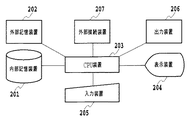
図2は、CAD装置のブロック図である。図2において、図中符号201は内部記憶装置、202は外部記憶装置であり、CADデータやCADプログラムを保管するRAM(random access memory)等の半導体記憶装置、磁気記憶装置等からなる。
【0044】
203はCPU(central processing unit)装置であり、CADプログラムの命令に沿って処理を実行する。
【0045】
204は表示装置であり、CPU装置203の命令に沿って形状などを表示する。
【0046】
205はCADプログラムに対して指示等を与えるマウス、キーボードなどの入力装置である。
【0047】
206はCPU装置203の命令に沿って紙図面などを出力するプリンタなどの出力装置である。
【0048】
207は外部接続装置であり、本CAD装置と外部の装置とを接続し、本装置からのデータを外部装置へ供給したり、外部の装置から本装置を制御したりする。
【0049】
図3は、図2に示したCAD装置の処理動作を示すフローチャートである。 まず、オペレータが入力装置205により、CADプログラムの起動を指示すると、外部記憶装置202に格納されているCADプログラムが内部記憶装置201に読み込まれ、CADプログラムがCPU装置203上で実行される(ステップS301)。
【0050】
オペレータが入力装置205により対話的に指示することにより、内部記憶装置201上に形状モデルを生成し、表示装置204上に画像として表示する(ステップS302)。この形状モデルについては、後述する。なお、オペレータが入力装置205によりファイル名などを指定することにより、既に外部記憶装置202上に作成されている形状モデルをCADプログラム上で取り扱えるように、内部記憶装置201に読み込むこともできる。
【0051】
オペレータが入力装置205により、形状モデルを作成した3次元空間内に、属性配置平面を作成する(ステップS303)。
【0052】
この属性配置平面の位置が判別しやすいように、フレーム(2重枠、枠内塗りつぶし)などの画像情報として表示装置に表示する。また、属性配置平面の設定情報は形状モデルに関連付けられて内部記憶装置201に保管される。
また、必要に応じて作成した属性配置平面に名称をつけることが望ましい。
【0053】
次に、オペレータが入力装置205により、属性配置平面上に形状モデルの投影形状を作成する。その投影形状は、属性配置平面の方向により、いわゆる平面図、正面図等の六面図に相当する投影形状、および断面が投影された断面の投影形状のいずれかである(ステップS304)。投影形状はモデル全体を投影させたものが好ましいが、面あるいは稜線を選択的に、あるいは部分的に投影させてもよい。
【0054】
ここで、投影形状と属性配置平面とは関連付けられて、その関連情報は内部記憶装置201に保管される。
【0055】
次に、オペレータが入力装置205により、形状モデルに対して、寸法、寸法公差、テキスト(注記)などを属性情報として付加する(ステップS305)。付加された属性情報は、ラベルなどの画像情報として、形状モデルと投影された形状と共に表示装置に表示することができる。付加された属性情報は、形状モデルに関連付けられて内部記憶装置201に保管される。
【0056】
次に、オペレータが入力装置205により、属性情報を属性配置平面に対して関連付ける(ステップS306)。属性情報と属性配置平面の関連情報は、内部記憶装置201に保管される。
【0057】
オペレータがあらかじめ属性配置平面を指定して、属性配置平面属性配置平面との関連付けを行いながら属性付けを行うようにしても良い。また、オペレータが入力装置205により、属性情報の属性配置平面への関連付けを設定・解除することができる。
【0058】
次に、オペレータは入力装置205により、属性配置平面を指定することによって属性配置平面、その属性配置平面に関連付けられた投影形状、およびその属性配置平面に関連付けられた寸法公差、テキスト(注記)などの属性情報の表示・非表示、あるいは色付けなどの表示制御を行う(ステップS307)。
【0059】
また、オペレータが入力装置205により属性配置平面を作成する際に、属性配置平面の視点の位置、視線方向、倍率を設定する(ステップS307)。この属性配置平面の表示情報を設定し、この属性配置平面を指定することで、設定された視点の位置、視線方向、倍率で形状モデルを表示することが出来る。またこの属性配置平面と属性情報は関連付けられているので、指定された属性配置平面に関係付けられている属性情報を選択的に表示することができる。属性配置平面の表示情報は内部記憶装置に保管される。
【0060】
また、属性情報に識別子を付加することができ、この識別子を付加して外部記憶装置202に保管することができる。この識別子を利用して他のデータと属性データを関連付ける。
【0061】
また、外部記憶装置202上の属性情報に情報を追加したものを内部記憶装置201に読み込んで、属性情報を更新することができる。
【0062】
そして、オペレータが入力装置205により、形状モデルに属性配置平面の位置情報、属性配置平面上の投影形状、属性配置平面の表示情報、および属性情報を付加したCAD属性モデルを外部記憶装置202に保管する(ステップS308)。
【0063】
ここで、形状モデルとCAD属性モデルについて説明する。
図4(a)、(b)は形状モデルの例を示す図であり、図5は形状モデルを構成する各部の関連を示す概念図である。
【0064】
図4(a)、(b)は、形状モデルの代表例として、SolidModelである。図に示すように、SolidModelは部品などの形状をCAD上の3次元空間上に定義する表現方法で、位相情報(Topology)と幾何情報(Geometory)からなる。SolidModelの位相情報は、図5に示すように、内部記憶装置201上で階層的に記憶され、
1つ以上のShellと、
1つShellに対して1つ以上のFaceと、
1つのFaceに対して1つ以上のLoopと、
1つのLoopに対して1つ以上のEdgeと、
1つのEdgeに対して2個のVertexと
からなる。
【0065】
また、Faceに対して平面や円筒面といったFace形状を表現するSurface情報が内部記憶装置201上で関連付けられて保管される。Edgeに対して直線や円弧といったEdgeの形状を表現するCurve情報が内部記憶装置201上で関連付けられて保管される。Vertlexに対して三次元空間上の座標値を内部記憶装置201上で関連付けられて保管される。
【0066】
Shell、Face、Loop、Vertexの各位相要素には、夫々属性情報が内部記憶装置201上で関連付けられて保管されている。
【0067】
ここで、Face情報を例に、内部記憶装置201上での保管方法の一例を説明する。
【0068】
図6は、内部記憶装置201上でのFace情報の保管方法を示す概念図である。
図に示すように、Face情報はFaceID、Faceを構成するLoopListへのポインタ、Face形状を表すSurfaceデータへのポインタ及び属性情報へのポインタからなる。
【0069】
LoopListは、Faceを構成する全てのLoopのIDをリスト形式で保管したものである。Surface情報は、SurfaceTypeとSurfaceTypeに応じたSurfaceParameterから構成される。
【0070】
属性情報は、属性タイプ及び属性タイプに応じた属性値から構成される。属性値には、Faceへのポインタや属性が所属するグループへのポインタなども含まれる。
【0071】
《3Dモデルの投影形状と属性情報の入力と表示》
次に、3Dモデルへの属性情報の入力、属性配置平面の作成方法、および属性情報が付加された3Dモデルと属性配置平面上の投影形状の表示について、詳細に説明する。
【0072】
図7〜図11は、3Dモデル、属性配置平面、投影形状、および属性情報を示す図であり、図12〜図14は3Dモデルに属性配置平面、投影形状、および属性情報を付加するときの処理動作を示すフローチャートである。
【0073】
図12のステップS121で、図7に示す3Dモデル1を作成し、作成した3Dモデル1に属性情報を付与するために、ステップS122で必要な属性配置平面を設定する。
【0074】
ここで、属性配置平面は、3Dモデル1、および3Dモデル1に付加された属性情報の表示に関わる要件を規定するものである。
【0075】
本実施形態では、属性配置平面を(仮想的な)三次元空間上の一点(以下、視点という)の位置、作成する平面の法線方向(視線方向)で定義し、更に3Dモデル1、および3Dモデル1に付加された属性情報の表示倍率(以下単に倍率)の情報も有するものとする。
【0076】
すなわち、視点の位置とは、視線方向において属性配置平面が設定される位置であり、例えば属性配置平面211、212、213は3Dモデル1の最外形から60mmの位置に設定される(図7)。
【0077】
ただし、ここで、いわゆる三角法による投影図(正面図、平面図、左右の側面図、下面図、背面図)の視線方向に相当する属性配置平面については、視点の位置が3Dモデル1の外部に位置していれば、いずれの位置でも表示内容には関係しない。
【0078】
また、その視点の位置は、3Dモデル1、および3Dモデル1に付加された属性情報を表示する際に表示装置204の表示中心と一致する点である。
次に、法線方向はその視点の位置から、3Dモデル1、および3Dモデル1に付加された属性情報を表示する際の視線方向と一致させる。
【0079】
また、倍率とは(仮想的な)三次元空間上の3Dモデル形状を表示装置204上で表示する際の拡大する倍率とする。
【0080】
属性配置平面のパラメータである、視点の位置、視線方向、倍率は随時変更可能とする。
【0081】
例えば、図7においては、いわゆる正面図、平面図、右側面図の方向に相当する属性配置平面211、212、213が設定される。視線方向は3Dモデルの外から内部へ向かう向きが定められる。図7においては、属性配置平面211は3Dモデル1の正面201aと平行であり、属性配置平面212は3Dモデル1の上面201bと平行であり、属性配置平面213は3Dモデル1の側面201cと平行の関係となる。視点の位置と倍率は、3Dモデル1の形状と付与する属性情報の概ね全てが表示装置204の表示画面に表示できるように定められる。
【0082】
各属性配置平面の位置を明示するために、属性配置平面を枠取りした四角で表現してある。この属性配置平面の位置を明示する手段として本実施例では枠を用いて表現したがこれに限られるものではなく、形状としては、四角以外の多角形、あるいは円形であっても良い。
【0083】
次に、投影形状を設定する(ステップS123)。投影形状は、上記各属性配置平面211,212,213に対し、3Dモデル1の外形形状が投影される形状である。例えば図7に示すように正面図の視線方向に相当する属性配置平面211上に投影形状2、平面図の視線方向に相当する属性配置平面212上に投影形状3、右側面図の視線方向に相当する属性配置平面213上に投影形状4、および図8に示すように断面図の視線方向に相当する属性配置平面214上に投影形状5が設定される。投影形状は、各々の属性配置平面を選択することにより、外形形状を一括して投影する、あるいは単一の面を選択してその面の形状を投影する、あるいは複数の面を選択してその面の形状を投影する、のいずれの方法でもよいものである。
【0084】
上記の属性配置平面と投影形状は、3Dモデル1と同じ三次元空間内に配置されているため、3Dモデル1を三次元的に回転、ズームイン/アウト等すれば、3Dモデル1と共に回転、ズームイン/アウト等できるものである。必要に応じ、随時属性配置平面および投影形状が追加設定あるいは削除されることは言うまでもない。
【0085】
次に、ステップS124で設定された各属性配置平面に関連付けて、各属性配置平面の視線方向に正対するように、属性情報を入力する。図9は正面図の視線方向に相当する属性配置平面211上に属性情報を付与した状態を示す図である。図10(a)、(b)、(c)は各々の属性配置平面の視線方向から見た3Dモデル1、投影形状2,3,4および属性情報である。ここで、属性情報は投影形状と同様に属性配置平面上に配置されるものである。属性情報の配置についての詳細は後述する。なお、図10においては、投影形状2、3、4は3Dモデル1の形状に重なって表示されている。
【0086】
属性配置平面に関連付けられた属性情報の大きさ(文字やシンボルの高さ)を、属性配置平面の倍率に応じて変更する。属性情報の大きさ(mm)とは、3Dモデル1が存在する仮想的3次元空間における大きさと定義する(表示装置204において表示された際の大きさではない)。属性情報が別の属性配置平面に関連付けられた場合、変更先の属性配置平面の倍率に応じて属性情報の大きさを変更する。
【0087】
また、各属性配置平面と属性情報の関連付けは、属性情報の入力後でもよい。たとえば図13に示すフローチャートのように、3Dモデル1を作成し(ステップS131)、ステップS132にて属性を入力、ステップS133、S134で属性配置平面と投影形状を作成後、ステップS135にて所望の属性配置平面に属性情報が関連付けられるものである。また、必要に応じ、属性配置平面に対し関連付けられる属性情報の追加、削除等の修正がなされるものである。
また、投影形状の作成は、属性情報の入力後でもよい。
【0088】
属性情報の入力は、3Dモデル1および所望の投影形状を二次元的に表示させて入力させてもよく、また必要に応じ、三次元的に表示させながら入力してもよい。その入力はいわゆる2D−CADで二次元図面を作成する工数と何ら変わることなく実現できるものである。さらには、必要に応じ三次元的に3Dモデル1を見ながら入力することができるので、より効率的かつミスなく実現できるものである。
【0089】
次に、属性配置平面上での2D図形およびテキスト情報を作成編集する場合の説明を行う。その2D図形およびテキスト情報は、例えば以下の情報を表記する場合に用いられるものである。
座標寸法記入法において、穴等を表す記号、および穴位置等の一覧表を作成編集する。
【0090】
また、寸法数値の代わりに、文字記号を用いる場合において、別に表示するテキスト、数値を作成編集する。
また、外形線の延長線の交点に寸法を付与するとき、交点を明らかにするために外形線の延長線を作成編集する。
また、隣接部分、あるいは工具、ジグなどの形状、位置を参考に表す線を作成編集する。
また、平面であることを表す細い実線を作成編集する。
また、テーパ・勾配を図示で明示するために、斜面から引出線を引き出して図と寸法を作成編集する。
また、特殊な加工部分の範囲を指示する線、および特殊な加工に関する必要事項に関するテキストを作成編集する。
また、矢視図あるいは部分拡大図等の文字あるいは倍率に関するテキストを作成編集する。
また、中心線あるいはかくれ線等を投影形状に付加する。
【0091】
上記各場合において、必要に応じ、いわゆる実線、破線、一点鎖線、二点鎖線の太線あるいは細線が用いられるものである。また、必要に応じ上記各種線の色が設定できるものである。
【0092】
また、上記各種の線は、属性配置平面上の任意の2点を指示する、1点と方向を指示する、あるいは中心と半径を指示する等のよく知られた各種の方法で作成される。また、線の作成に際し、必要に応じ3Dモデル1あるいは投影形状が利用されるのは言うまでもない。
【0093】
上記各種情報が所望の属性配置平面と関連付けられ、属性配置平面上に作成される。これにより、より分かりやすく適切な設計情報が表現可能となるものである。
【0094】
次に、3Dモデル1の属性情報を見る場合の説明を行う。図14のステップS141において所望の属性配置平面を選択することで、ステップS142において選択された属性配置平面の視点の位置、視線方向、および倍率に基づき3Dモデル1の形状とその属性配置平面に関連付けて付与されている投影形状と属性情報が表示されるものである。例えば属性配置平面211、属性配置平面212、あるいは属性配置平面213が選択されると、それぞれ図10(a)、(b)、あるいは(c)が表示される。このとき、属性情報は各属性配置平面の視線方向に正対して配置されているため、表示画面上では二次元的に極めて容易に分かりやすく見ることができる。
【0095】
さらには、3Dモデル1を回転させて三次元的に見る場合においても、投影形状と属性情報とが同一面上に配置されているために、極めて容易に分かりやすく見ることができる。例えば図9と図11とにおいて、投影形状2の有無を比較すれば明らかなように、投影形状2がある場合には属性情報の指示位置がより見やすくなるものである。
【0096】
次に、属性配置平面を容易に選択可能とするための例を紹介する。まず、選択可能な3Dモデルの属性配置平面の枠を表示させ、オペレタータが、マウスなどのポインティングデバイス等の入力装置を使用して、属性配置平面を選択する方法が考えられる(図7)。
【0097】
次に、選択可能な属性配置平面の名称をリスト形式で表示して、その中から選択する方法も考えられる(不図示)。
【0098】
さらには、属性配置平面の視線方向から見た状態(図10(a)、(b)、あるいは(c))の画像をサムネイル画像としてアイコン表示して、選択する方法も考えられる。
【0099】
《属性情報の他の入力方法》
図11〜図14を用いて説明した上述の属性情報の入力においては、各属性配置平面に属性情報を関連付けたが、関連付ける手段は上記に限定されるものではなく、例えば属性情報をグループ化し、そのグループと属性配置平面を関連付けてもよい。
【0100】
図15、図16に示すフローチャートに基づき、説明する。
あらかじめ入力された属性情報を選択的に、あるいは検索結果に基づきグループ化し、そのグループと任意の属性配置平面関連付けすることで上記と同様の結果および効果が得られる。また、属性情報のグループへの追加、削除等の修正がなされることにより、属性配置平面に関連付けられる属性情報を操作することができる。
【0101】
即ち、3Dモデルを生成し(ステップS151)、属性情報を入力し(ステップS152)、3Dモデルに対し属性配置平面の視点の位置、視線方向、および倍率を設定する(ステップS153)。そして、ステップS152で入力され属性情報をグループ化し、設定した属性配置平面とグループ化した属性情報とを関連付けて設定するものである(ステップS154)。
【0102】
また、表示を行うときは、図16に示すように、属性配置平面選択し(ステップS161)、選択された属性配置平面に関連付けられている属性情報を属性配置平面の視点の位置、視線方向、および倍率の情報に従って表示装置204で表示する(ステップS162)ものである。
【0103】
《断面の属性配置平面と投影形状の設定》
断面の投影形状5について、図17に基づきさらに説明する。3Dモデル1内の所望の位置に切断面を設定し(例えば、穴の中心を通り正面図に平行)、その切断面の表裏いずれかの法線方向を視線方向として属性配置平面214を設定する。例えば、視線方向に対し切断面の手前側を非表示とすることで、3Dモデル1の断面形状を表示することができる。断面および切断面の向こう側の形状の投影形状5は上記属性配置平面214上に配置される。その属性配置平面214に関連付けて属性情報を入力、表示することで、二次元的にも三次元的にも、断面形状および投影形状を見ながら、属性情報の指示箇所が容易にかつ即座に分かるものである。その属性情報は例えば、断面で表示しないと見えない面の寸法、注記、あるいは断面で表示しないと寸法引き出し線が見えない寸法等である。
【0104】
《複数の投影図の設定》
また、3Dモデル1の形状が同一に見える、すなわち視線方向が同一の属性配置平面を複数設定し、各々の属性配置平面に同一の投影形状を配置する構成としてもよい。断面の属性配置平面についても同様に、同一の切断面で、同一の視線方向である複数の属性配置平面を設定してもよい。
【0105】
図18に同一の視線方向の複数の属性配置平面215、216、および各々の属性配置平面215、216に投影された同一の複数の投影形状6、7を示す。図18においては、属性配置平面215と属性配置平面216とは3Dモデル1の平面図に相当する属性配置平面215、216である。各々の属性配置平面215、216に属性情報を、例えばグループ化し関連付けることで、より見やすい属性情報を実現できる。例えば、属性配置平面215には3Dモデル1の概略の外形寸法に関わる属性情報を関連付け、属性配置平面216には3Dモデル1の細かい(詳細の)形状を関連付けることができる(図19)。この場合、属性配置平面215、216の倍率を異なる設定とすることができるものである。属性配置平面215に関連付けられるビューの倍率を1、属性配置平面216に関連付けられるビューの倍率を2とすることで、細かい形状と関連付けられた属性情報も容易に分かりやすく見ることができる。
【0106】
また、複数の属性配置平面の設定においては、穴位置および穴形状に関わる属性情報、あるいは印刷、塗装等の二次加工に関連する属性情報等、属性情報の種類ごとに関連付ける属性配置平面を設定するという取り扱いもできるものである。
【0107】
《属性情報の配置》
3Dモデルとその3Dモデルに付加する属性情報を2次元な図面として極めてわかりやすく表示画面上で表現するため、オペレータは表現したい3Dモデルの部位の複数の属性情報を適宜選択もしくはグループ化して属性配置平面に関連付ける。2次元的な図面の表現方法であれば、属性情報の位置は関連する投影図の投影方向、すなわちビューの視線方向の領域に正対配置すればよいが、3Dモデルに属性情報を付加し図面とするいわゆる「3D図面」においては、3Dモデルのメリットを十分生かすため工夫が必要となる。
【0108】
3Dモデルのメリットの一つは、表示画面上で実物に近い形で立体的に表現できるため、3Dモデルを作成するオペレータあるいはその3Dモデルを用いる次工程のオペレータ(工程設計者、金型設計・製作者、測定者等)にとって、2次元図を扱う際に必要となる2次元から3次元への変換作業(これは主にオペレータの頭の中で行われていた)が省ける点である。この変換作業はオペレータの力量によるところが多く、いきおいこの変換作業において誤変換による誤造や変換時間のロスが発生することがある。
【0109】
3D図面において、3Dモデルのメリットである立体的に表現できる点を損なわないために、立体表示した際の属性情報の表示(属性情報の配置)に工夫をする必要がある。
【0110】
その工夫する点について、図20(a)〜(d)を用いて説明を行う。
第一の工夫は、属性情報を配置する面についてである。
図20(a)は説明に使用する3Dモデル21の斜視図、図20(b)は3Dモデル2の平面図、図20(c)は3Dモデル21に工夫しないで属性情報を付加した状態を説明する斜視図、図20(d)は属性情報の配置を工夫して行った斜視図である。
【0111】
まず、3Dモデル21に対して、平面図を作成するため属性配置平面(不図示)、投影形状22、および属性情報の入力を行う。この属性配置平面の視線方向から表示した状態が図20(b)である。
【0112】
その属性情報の入力に関して、図20(c)の様に複数の属性情報の配置する面を互い違いにすると、属性情報が重なりあい属性情報の内容が判別し難くなる。図20(c)のように属性情報が少なくても見にくいので、より複雑な形状であれば、もはや属性情報は有益な情報ではなくなり、斜視状態では図面として成り立たなくなることは容易に想像できる。
【0113】
ところが、図20(d)の様に属性情報を投影形状22と同一平面内に配置することで属性情報どうしが重なり合うことはなく、2次元的な図面の表現(図20(b))と同等に属性情報の判別は容易にできる。
【0114】
こうすることで、3Dモデル21に属性情報を付加する図面形態(3D図面)において2次元的な図面の表現だけでなく、3Dモデル21のメリットである立体的に3Dモデル21を表現しながら、属性情報の判別が容易にできるので、立体図面(3D図面)として利用することが可能となる。
【0115】
上記は同一視線方向の複数の属性配置平面に属性情報を関連付ける場合においても同様である。
【0116】
また、同一視線方向に複数の属性配置平面を作成する際には、離して配置するのが好ましい(図18)。この複数の属性配置平面、各々の属性配置平面に投影された投影形状、および各々の属性配置平面に関連付けられている属性情報を同時に表示する際、属性配置平面を同一位置に作成すると各属性情報の配置面が同一面になるので、視線方向はもとより視線方向をずらして斜めから見ても属性情報同士が重なり見にくくなる。そもそも同一方向からみて属性情報が多いために複数の属性配置平面に分けており、同時に属性情報を表示する際には属性情報が重なってしまうことは避けられない。
【0117】
視線方向からの見にくいのは救えないとしても、斜視状態で属性情報を判別し易くするために手段として、同一視線方向の投影形状は離して配置するのが有効である。
【0118】
第二の工夫は、属性情報の引き出し方である。
属性情報を、3Dモデルから三次元空間内の投影形状が配置された属性配置平面に引き出すためには、引き出し線あるいは寸法補助線に相当する線を、例えば一度折り曲げてL字状に引き出す必要がある。この引き出し方としては、図21に示すように、3Dモデル31側で折り曲げる方法(まず3Dモデル31から属性情報を引き出し、寸法線等の位置で投影形状32が作成されている属性配置平面(不図示)に引き出す。線11)と、属性配置平面の面で折り曲げる方法(3Dモデル31と属性配置平面上の投影形状32をまず線で結び、属性配置平面において属性情報を引き出す。線12)とが考えられる。本発明においては、属性情報を投影形状をより有効に活用するために、上記属性配置平面の面上で折り曲げる方法が好ましい。その方法により、属性情報が投影形状のどの部位に関係しているのかが極めて明確となり、「3D図面」において、3Dモデルのメリットを十分に生かすことができるものである。
【0119】
《倍率》
次に、属性配置平面の倍率について説明する。倍率とは(仮想的な)三次元空間上の3Dモデル形状、投影形状、および属性情報を表示装置204上で表示する際の拡大縮小する倍率である。その倍率を所望の倍率とすることで、複雑な形状あるいは詳細な形状をより見やすくできる。また、サイズの大きな形状を縮小して形状全体を見ることで、形状がより理解しやすくなるものである。
【0120】
図22(a)、(b)、(c)は、3Dモデル51の一部を拡大して表示した状態を示す図である。例えば、図22(a)のように、3Dモデル51に対し、視線方向を平面図に対応する属性配置平面の視線方向に向け、視線中心を角部近傍とし、倍率を例えば5倍とするビューを設定することで、階段状の形状および属性情報が極めて分かりやすく表示できる。(図22(b))
本実施形態においては、3D−CAD装置を構成するハードウェア、あるいは3D形状モデルの構成方法によらず3D−CAD全般に対し有効である。
【0121】
さらに、属性配置平面(不図示)に関連付けられた属性情報の大きさ(文字やシンボルの高さ)は、属性配置平面に関連付けられる倍率に応じて変更するものとする。(図22(b))
属性情報の大きさ(単位は例えばmmとする)とは、3Dモデル51が存在する仮想的3次元空間における大きさと定義する(表示装置204において表示された際の大きさではない)。
【0122】
例えば、属性配置平面において倍率1の時の属性情報の大きさを3mmとする。その属性配置平面を倍率5で同じように文字高さを3mmとして表示した例を図22(c)で示す。属性配置平面に関連付けられた属性情報は5倍の表示倍率で表示されるのでその大きさは15mmとなる。見るために、表示される大きさが大きいのはよいことであるが、その15mmは必要以上に大きく、一度に見たい情報が多数ある場合には好適とは言えない。
【0123】
図22(b)、(c)において四角線は表示装置204での表示可能範囲を示す。
属性情報が重ならないように配置すると、3Dモデルおよび投影形状と、属性情報の位置が離れてしまうので形状とそれに関係する属性情報の関わりがわかりにくく、誤読する可能性も発生する。また表示したい属性情報が多いと全ての属性情報を表示装置204で表示しきれなくなり、表示可能範囲外の属性情報を見るために表示範囲を変更しなくてはならない煩わしさを伴う。
【0124】
また、縮小して表示したい場合(倍率は1未満)に文字の大きさを変更しないと、縮小図表示状態で属性情報の表示装置204上の表示大きさが小さくなり、属性情報の内容が判別できなくなる。
【0125】
そこで、属性情報が表示される時のことを考慮して、属性情報の情報の大きさを倍率によって変更するのが望ましい。
【0126】
そのため、倍率と属性情報の大きさをおおよそ反比例の関係にすると良い。例えば属性配置平面の倍率が1の時、属性情報の大きさを3mmと設定する場合、上記属性配置平面32のビューの倍率を5とすれば、関連付けられた属性情報の大きさを0.6mmとする。
【0127】
また、任意の属性配置平面に関連付けられている属性情報が他の属性配置平面に関連付けられた場合、変更先の属性配置平面の倍率に応じて属性情報の大きさを変更する。
【0128】
《投影図の複数選択》
上述の実施例において、属性配置平面に関連付けられた属性情報を表示する場合、選択対象の属性配置平面の数はただ一つとしていたが、本発明の目的を鑑みると、複数の属性配置平面を選択してもなんら問題ない。
【0129】
ただし、属性配置平面の単一選択を行う場合は、視線方向、倍率、視線中心が唯一つなので、表示装置上での表示方法は一つになるが、複数選択した場合は表示方法が複数になるので工夫をしなければならない。たとえば、複数選択を行った場合、選択された属性配置平面に関連付けられた属性情報をすべて表示し、視線方向、倍率、視線中心についてはどの属性配置平面の設定を採用するか選択できるようにすることが考えられる。
【0130】
また、属性情報の表示は関連する属性配置平面毎に色を変えるなどして、グループがわかりやすく判別できるように工夫を行う。
【0131】
《属性情報の表示方法》
上記従来例では、3Dモデル対して入力された属性情報を選択的に表示する順序として、まず最初に属性配置平面の選択を行い、次にその属性配置平面に関連付けられた属性情報を適宜表示する、この順番で説明を行ったが、この方法に限定されるものではなく、属性情報を選択し、その次に、その属性情報が関連付けられている属性配置平面の視線方向、倍率、視線中心で、3Dモデル、投影形状およびその属性情報を表示する手法も有効である。
【0132】
図23は、この一連の処理動作を示すフローチャートである。
図9の様に3Dモデル1と属性情報が表示された状態(他の属性配置平面に関連付けられている属性情報が同時に表示されていてもよいことは言うまでもない)で、属性情報(例えば35±0.3)を選択する(ステップS311)。
【0133】
この選択により、上記属性情報が関連付けられている属性配置平面の視線方向、倍率、視線中心に基づいて、3Dモデル1、投影形状、および属性情報を表示する(ステップS312)。この場合図10(b)で示す如く正面図が表示される。
これによって、選択された属性情報と3Dモデル1との関係が、2次元的に表示されるので、より認識しやすくなる。
【0134】
また、3Dモデルの幾何情報(稜線、面、頂点)を選択し、その幾何情報に関連付けられている属性情報の表示、さらにはその属性情報が関連付けられている属性配置平面の視線方向、倍率、視線中心で、3Dモデル、投影形状およびその属性情報を表示する手法も有効である。
【0135】
図24(属性情報選択から表示)は、この一連の処理動作を示すフローチャートである。
3Dモデルの幾何情報を選択する(ステップS321)。
選択した幾何情報に関連付けられている、属性情報を表示する(ステップS322)。
関連付けられている、属性情報が複数存在するならば、それらをすべて表示しても良い。また、属性情報が関連付けられている属性配置平面に属する属性情報すべてを表示してもよい。
【0136】
次に、表示した属性情報に関連する属性配置平面の、視線方向、倍率、視線中心に基づいて3Dモデル、投影形状および属性情報を表示する。
このように、3Dモデルの幾何情報から、関連する属性情報の検索および、表示が出来るのでとても使いやすい。
【0137】
《表示》
ここで、上述のように作成した属性情報が付加された3Dモデルの表示について述べる。
【0138】
図2に示した情報処理装置で作成した属性情報が付加された3Dモデルは、作成した装置自身、或いは、外部接続装置を介して作成した3Dモデルのデータを転送することにより、他の同様な情報処理装置を用いて、図1に示した各工程で表示し、利用することができる。
【0139】
まず、3Dモデルを作成した、製品/ユニット・部品の設計技術者あるいはデザイン設計者であるオペレータ自身が、自ら作成した3Dモデルを、図10(a)、(b)、(c)に示すように表示を行うことで、あたかも二次元の図面を作成するごとく3Dモデルに新たな属性情報を付加することができるものである。また、例えば、形状が複雑な場合に、必要に応じて3Dモデルを3次元表示と二次元的表示とを交互に、或いは、同一画面に表示することにより、効率良くかつ正確に所望の属性情報を入力していくことができる。
【0140】
また、作成された3Dモデルをチェック/承認する立場にあるオペレータが、作成した3Dモデルを図10(a)、(b)、(c)に示す表示を、同一画面或いは切替えて表示することにより、チェックを行い、チェック済み、OK、NG、保留、要検討などを意味するマーク、記号、或いは色つけなどの属性情報が付加される。必要に応じて、複数の製品/ユニット/部品を比較、参照しながらチェックが行われるのは言うまでもない。
【0141】
また、作成された3Dモデルの作成者以外の設計技術者あるいはデザイン設計者が、作成された3Dモデルを参照して、他の製品/ユニット/部品を設計する場合に利用することができる。この3Dモデルを参照することにより、容易に作成者の意図、あるいは設計手法を理解できるものである。
【0142】
また、3Dモデルを製作、製造するに当たり、そのために必要な情報を3Dモデルあるいは属性情報に付与するオペレータが利用することができる。この場合、オペレータは製品/ユニット/部品の製作工程を設定する技術者である。オペレータは、例えば加工工程の種類、使用する工具等の指示、あるいは3Dモデルへ加工上必要な稜線部、角部、隅部等へのコーナR、面取りを付加する。あるいは寸法、寸法公差等に対する測定方法の指示、測定点の3Dモデルへの付加、測定上注意すべき情報等を入力する。これらは、図10(a)、(b)、(c)のように見やすく配置作成された表示を見ながら、また必要に応じ三次元的に形状を確認しながら、効率良く確実に行われる。
【0143】
また、3Dモデルを製作、製造するに当たり、所望の準備をするために必要な情報を3Dモデルあるいは属性情報から得るオペレータが利用することができる。この場合、オペレータは製作、製造に必要な金型、治工具、各種装置等を設計する設計技術者である。オペレータは3Dモデルを三次元状態で見ながら形状を理解、把握しつつ、必要な属性情報を図10(a)、(b)、(c)のように見やすく配置作成された表示でチェック、抽出していく。それらの属性情報を元に、オペレータは金型、治工具、各種装置等を設計する。例えば、オペレータが金型の設計技術者である場合は、オペレータは3Dモデルおよび属性情報から、金型の構成、構造等を検討しつつ設計する。また、必要に応じ、金型製作上必要な稜線部、角部、隅部等へのコーナR、面取りを付加する。また、金型が樹脂の射出成形用金型の場合には、オペレータは、例えば3Dモデルに成形上必要な抜き勾配等を付加する。
【0144】
また、製品/ユニット/部品を製作、製造するオペレータが利用することができる。この場合、オペレータは製品/ユニット/部品の加工技術者、組立て技術者である。オペレータは3Dモデルを三次元状態で見ながら加工すべき形状、あるいは組み立てるべき形状を容易に理解、把握しつつ、図10(a)、(b)、(c)のように見やすく配置作成された表示を見て加工、組立てを行う。そして必要に応じ、オペレータは加工部、組立て部の形状等をチェックする。また、加工済み、加工が困難、あるいは加工結果等を属性情報として3Dモデルあるいはすでに付加されている属性情報に付加し、その情報を設計技術者等にフィードバックしてもよい。
【0145】
また、製作、製造された製品/ユニット/部品を検査、測定、評価するオペレータが利用することができる。この場合、オペレータは製品/ユニット/部品の検査、測定、評価する技術者である。オペレータは、上記の寸法、寸法公差等に対する測定方法、測定点、測定上注意すべき情報を、図10(a)、(b)、(c)のように見やすく配置作成された表示を見ながら、また必要に応じ三次元的に形状を確認しながら、効率良く確実に得て、検査、測定、評価を実行する。そして、オペレータは必要に応じ、検査、測定、評価を属性情報として、3Dモデルに付与することができる。例えば、寸法に対応する測定結果を付与する。また、寸法公差外、キズ等の不具合箇所の属性情報あるいは3Dモデルにマークあるいは記号等を付与する。また、上記チェック結果と同様に、検査、測定、評価済みのマーク、記号、あるいは色付け等がなされてもよい。
【0146】
また、製品/ユニット/部品の製作、製造に関係する各種の部門、役割のオペレータが利用することができる。この場合、オペレータは例えば、製作、製造コストを分析する担当者、あるいは製品/ユニット/部品自体、関連する各種部品等を発注する担当者、製品/ユニット/部品のマニュアル、梱包材等を作成する担当者、等である。この場合もオペレータは3Dモデルを三次元状態で見ながら製品/ユニット/部品の形状を容易に理解、把握しつつ、図10(a)、(b)、(c)のように見やすく配置作成された表示を見て効率的に各種業務を遂行する。
【0147】
《検査指示の入力》
次に、検査指示に関して述べる。
出来上がった金型や、部品などを検査するためには、予め、3Dモデルに寸法などを割り当てて表示することは上述した通りである。
【0148】
ここでは、設定された属性配置平面に対して、検査する位置が明確となる表示となるように属性情報を入力する。
【0149】
即ち、3Dモデルを構成する、面、線、稜線などに対して、検査する順番、検査位置、検査項目などを入力する。そして、その順番に検査することにより、検査工数を軽減するものである。
【0150】
まず、検査する項目と位置を入力することにより、全体が入力される。次に、所定の方法により、検査の順番を割り振り、それぞれの項目に順番を割り当てる。そして、実際に検査を行う場合は、順番を指示することにより、属性配置平面が選択され、表示されている属性配置平面において、検査すべき位置の面などが、他と異なった形態(色などが異なる)で表示され、検査位置が明確になる。
そして、指示された検査項目毎に、検査した結果を入力し、再成形が必要か否かが判断されるものである。
【0151】
以上説明のように本発明の実施形態によれば、設定された属性配置平面と属性情報により、簡単な操作で見やすい画面を得ることができる。また、視線方向と属性情報の関係も一覧してわかるものである。さらには、あらかじめ寸法値などが入力されていることにより、オペレータによる操作ミスによる誤読が軽減される。
【0152】
また、属性配置平面に関連付けられた情報のみを見ることができ、必要とする情報を容易に知ることができる。
【0153】
また、同一視線方向の大量の属性情報を、複数の属性配置平面に割り当てることにより、見やすい画面を得ることができ、必要な情報を容易に知ることができる。
【0154】
また、3Dモデルの内部、即ち、断面位置に属性配置平面を設定することにより、属性情報をわかりやすく表示することができる。
【0155】
また、属性配置平面の表示倍率にしたがって、属性情報の大きさを変更するので、わかりやすくそして、適切に表現できる。
【0156】
また、属性情報と投影形状を属性配置平面に配置することで、3Dモデルを斜めから見た立体的な表現を行っても、属性情報を読み取ることが出来る。
【0157】
さらには、属性配置平面上に2D図形あるいはテキスト情報を作成することで、より分かりやすく適切な表現、表示ができる。
【0158】
また、属性情報から、属性配置平面の検索および、その属性配置平面に関連付けられた情報のみを見ることができ、必要とする情報を容易に知ることができる。
【0159】
また、幾何情報から、属性情報および属性配置平面の検索さらには、その属性配置平面に関連付けられた情報のみを見ることができ、必要とする情報を容易に知ることができる。
【0160】
【発明の効果】
以上説明したように本発明によれば、属性情報を所望の仮想平面上に入力配置でき、またその仮想平面上に3Dモデルを投影した投影形状を作成することで、属性情報の数によらず極めて容易に入力が可能となり、また見やすく、かつ分かりやすく確実に情報が伝達できる。
【0162】
また、本発明によれば、3Dモデルの形状データからいわゆる二次元的に形状を表した二次元図面を作成することなく、3Dモデルと属性情報と仮想平面上の2D図形とテキスト情報で、効率良く設計情報を伝達できる。
【図面の簡単な説明】
【図1】本発明の実施形態のモールド部品金型生産の全体の流れを示す図である。
【図2】本発明の実施形態のCAD装置のブロック図である。
【図3】図2に示したCAD装置の処理動作を示すフローチャートである。
【図4】本発明の実施形態の形状モデルの例を示す図で、(a)はSolidModelの図、(b)はShellの図を示す。
【図5】本発明の実施形態の形状モデルを構成する各部の関連を示す概念図である。
【図6】本発明の実施形態の内部記憶装置201上でのFace情報の保管方法を示す概念図である。
【図7】本発明の実施形態の3Dモデル、属性配置平面および投影形状を示す図である。
【図8】本発明の実施形態の3Dモデルおよび断面の属性配置平面および投影形状を示す図である。
【図9】本発明の実施形態の3Dモデル、属性配置平面、投影形状および属性情報を示す図である。
【図10】本発明の実施形態の各属性配置平面から見た3Dモデルと属性情報を示す図で、(a)は平面図の視線方向から見た3Dモデルおよび属性情報、(b)は正面図の視線方向から見た3Dモデルおよび属性情報、(c)は右側面図の視線方向から見た3Dモデルおよび属性情報を示す図である。
【図11】本発明の実施形態の3Dモデル、属性配置平面および属性情報を示す図である。
【図12】本発明の実施形態の3Dモデルに属性情報を付加するときの処理動作を示すフローチャートである。
【図13】本発明の実施形態の3Dモデルに属性情報を付加するときの処理動作を示すフローチャートである。
【図14】本発明の実施形態の3Dモデルに属性情報を付加するときの処理動作を示すフローチャートである。
【図15】本発明の実施形態の3Dモデルに属性情報を付加するときの処理動作を示すフローチャートである。
【図16】本発明の実施形態の属性情報を付加された3Dモデルの表示を行うときのフローチャートである。
【図17】本発明の実施形態の3Dモデル、断面の属性配置平面と投影形状、および属性情報を示す図である。
【図18】本発明の実施形態の3Dモデルに複数の属性配置平面と投影形状を設定した状態の図である。
【図19】本発明の実施形態の3Dモデル、投影形状および属性情報を示す図である。
【図20】本発明の実施形態の3Dモデルの一例を示す図で、(a)は3Dモデルの斜視図、(b)は3Dモデルの平面図、(c)は3Dモデルに工夫しないで属性情報を付加した状態を説明する斜視図、(d)は属性情報の配置を工夫して行った斜視図を示す。
【図21】本発明の実施形態の属性情報の引き出し方の説明図である。
【図22】本発明の実施形態の3Dモデルの一部に属性配置平面を割り当てた場合を示す図で、(a)は3Dモデルの図、(b)は階段状の形状および属性情報を分かりやすく表示した図、(c)は投影図を倍率5のビューで文字高さを3mmとして表示した例を示す図である。
【図23】本発明の実施形態の属性情報から3Dモデルと属性情報の表示を行うときのフローチャートである。
【図24】本発明の実施形態の幾何情報から3Dモデルと属性情報の表示を行うときのフローチャートである。
【図25】従来の3Dモデルの一例を示す図である。
【図26】従来の図25に示した3Dモデルの図で、(a)は平面図、(b)は側面図、(c)は正面図を示す。
【図27】従来の図25に示した3Dモデルに属性情報を付与した状態の図である。
【符号の説明】
1、21、31、41、51 3Dモデル
2、3、4、5、6、7、22、32 投影図
11、12 寸法補助線
32 投影図
201 内部記憶装置
201a 正面
201b 上面
201c 側面
202 外部記憶装置
203 CPU装置
204 表示装置
205 入力装置
206 出力装置
207 外部接続装置
211、212、213、214、215、216 属性配置平面[0001]
BACKGROUND OF THE INVENTION
The present invention Is 3 Information processing equipment using 3D model (3D shape) created using D (dimensional) -CAD (computer aided design) In place Related.
[0002]
[Prior art]
2. Description of the Related Art Conventionally, an article having a three-dimensional shape (hereinafter, simply referred to as a part) such as a product or a part constituting a product has been designed using a CAD apparatus (particularly a 3D-CAD apparatus).
[0003]
Based on the above design, parts are manufactured or molds for creating parts are manufactured.
[0004]
In addition, when using design information created by a CAD device, attribute information such as dimensions, dimensional tolerances, geometrical tolerances, notes, symbols, and the like is input and added to a 3D model (3D shape).
[0005]
In order to input attribute information to the 3D model, it is performed by instructing and selecting a surface, a ridgeline, a centerline, or a vertex of the 3D model. For example, in the
[0006]
Here, the attribute information is
Dimensions such as distance (length, width, thickness, etc.), angle, hole diameter, radius, chamfer, and dimensional tolerances associated with that dimension,
Alternatively, geometrical and dimensional tolerances that are added to surfaces, ridges, etc. without input of dimensions, or notes that should be instructed to be communicated when processing or manufacturing parts, units, or products.
Or a symbol that has been decided as a convention such as surface roughness
Etc.
[0007]
There are the following two types of methods for attaching attribute information to a 3D model.
(1) When adding dimensions, dimensional tolerances, geometrical tolerances, notes, and symbols
Dimension lines and extension lines are required to enter dimensions and dimensional tolerances, and leader lines are required to enter geometric tolerances, notes, and symbols.
(2) When dimension tolerance, geometric tolerance, notes, and symbols are added without dimensions
Dimension lines and extension lines are not required, but lead lines are required to enter dimensional tolerances, geometrical tolerances, notes, and symbols.
[0008]
If auxiliary line, symbol, or text information is required to give the attribute information, a so-called two-dimensional drawing representing the shape in two dimensions is created from the shape data of the 3D model. It is represented on a two-dimensional drawing. The information is, for example, the following information in JIS B 0001 mechanical drawing.
List of symbols indicating holes in the coordinate dimensioning method, and hole positions
Numerical value to be displayed separately when using text symbols instead of dimension values
Extension line when adding dimensions to the intersection of the extension lines of the outline
Shown by reference to the shape and position of adjacent parts or tools and jigs
A thin solid line representing a flat surface
Specify taper / gradient in illustration
Special machining areas and special machining requirements
Character or magnification notation such as arrow view or enlarged view
In addition, it is necessary to measure and inspect whether the manufactured part, the manufactured mold, and the molded product formed by the mold are completed as designed.
[0009]
[Problems to be solved by the invention]
The method of attaching attribute information to the 3D model as in the conventional example has the following problems.
[0010]
In the case of (1) above, the dimensions and dimensional tolerances, and the dimension lines and dimension auxiliary lines for entering them become complicated, making it difficult to see the shape and attribute information of the 3D model.
[0011]
As shown in FIG. 27, if the number of pieces of attribute information is a relatively simple shape and about several tens, it can be seen. However, in the case of a complicated shape or a large shape, several hundred to several thousand are necessary. Since the attribute information is added to the 3D model, “the attribute information overlaps”, “the attribute information overlaps the dimension line, the dimension extension line, or the lead line”, “the dimension line, the dimension extension line, or the lead line” It is very difficult to read the attribute information because it is difficult to understand the position of the drawer, etc. (even the stepped shape at the corner of FIG. 27 is somewhat difficult to see).
[0012]
In such a case, it is difficult for an operator who inputs attribute information to see the input information, and the input content cannot be confirmed, that is, it becomes difficult to input the attribute information itself.
[0013]
Also, reading related attribute information becomes extremely difficult. Further, the space occupied by the attribute information with respect to the 3D model becomes large, and it becomes impossible to view the shape of the 3D model and the attribute information at the same time on a limited display screen.
[0014]
Further, the attribute information to be instructed by a so-called sectional view or the like (for example,
[0015]
In the case of (2) above, the dimension line and the auxiliary dimension line are not necessary, but since the lead line is used, the lead line becomes complicated as in (1) above, and the shape and attribute information of the 3D model is not obtained. It becomes difficult to see. In the case of a complicated shape or a large shape, attribute information is extremely difficult to read because hundreds to thousands of attribute information is added to the 3D model as necessary.
[0016]
Moreover, when manufacturing a metal mold | die and inspecting the completed metal mold | die and the molded article shape | molded with the metal mold | die, it is necessary to measure a dimension. For this reason, in order to read the dimension value, a measurement operation using a measurement function of the 3D model shape is forced.
[0017]
In this case, it is necessary to specify and select a reference point for the dimensions such as the surface or ridgeline to be read. When reading the dimensions of multiple parts, it takes many operations and a long operation time. It is what will end up. In addition, the possibility of misreading due to operational mistakes is inevitable. Furthermore, when reading the dimensions of all the places, an extremely large amount of labor is required.
[0018]
In the first place, the so-called design information of the 3D model and attribute information is information for processing and manufacturing parts, units, and products. From the input operator = designer to the viewing operator = engineer for processing, manufacturing, inspection, etc. , Information must be easy to understand, efficient, communicated without error. In the above-mentioned prior art, these are not satisfied at all, and are not in a form that can be used industrially effectively.
[0019]
In addition, when auxiliary line, symbol, or text information is required to give the attribute information, a so-called two-dimensional drawing is created from the data of the 3D model and expressed on the two-dimensional drawing. In order to input or view all of the design information, a 3D model, attribute information, and a two-dimensional drawing must be prepared. This is very inefficient both when inputting and viewing.
[0020]
Furthermore, the 3D model, the attribute information, and the two-dimensional drawing are required to be consistent as design information. That is, the 3D model and the two-dimensional drawing need to have the same shape. Also, attribute information and 2D drawing information must not overlap to avoid misunderstandings and confusion. These are required to maintain consistency even when the shape or the like is changed, and this requires a lot of labor in operation.
[0021]
The present invention has been made in view of such problems, and the object of the present invention is to input and add attributes to data created by a CAD device or the like that are easy to input and easy to view, that is, with good operability. Information processing equipment Place It is to provide.
[0022]
In addition, an object of the present invention is to provide an information processing device in which added attributes are easy to see, understand and reliably transmit design information. Place It is to provide.
[0023]
An object of the present invention is to effectively use data created by a CAD device or the like, and without using a two-dimensional drawing, an information processing device that efficiently produces parts using the data. Place It is to provide.
[0024]
Furthermore, an object of the present invention is to provide an information processing apparatus that efficiently performs an inspection step using data created by a CAD device or the like. Place It is to provide.
[0025]
[Means for Solving the Problems]
In order to achieve such an object, the information processing apparatus of the present invention projects a 3D model onto a virtual plane associated with attribute information for the 3D model. The association means is provided with attribute information on the virtual plane so as to face the line-of-sight direction of the virtual plane. And a leader line connecting the 3D model and the projected shape of the 3D model on the virtual plane in a three-dimensional space in which the 3D model and the virtual plane are arranged. In the line of sight Display means to display And the display means extracts and displays the attribute information on the virtual plane from the projection shape of the 3D model, and arranges the projection shape and the attribute information on the same plane. It is characterized by that.
[0027]
With the above configuration of the present invention, attribute information can be input and arranged on a desired virtual plane, and by creating a projection shape by projecting a 3D model on the virtual plane, it is extremely easy regardless of the number of attribute information. Input is possible, information is easy to see, easy to understand, and can be transmitted reliably.
[0032]
With the above configuration of the present invention, it is possible to efficiently use the 3D model, the attribute information, the 2D figure on the virtual plane, and the text information without creating a so-called two-dimensional drawing representing the shape in two dimensions from the shape data of the 3D model. It can communicate design information well.
[0033]
DETAILED DESCRIPTION OF THE INVENTION
An embodiment of the present invention will be described in detail with reference to the drawings.
[0034]
<Overall flow of mold production>
FIG. 1 is a diagram showing an overall flow of mold part mold production according to an embodiment of the present invention.
[0035]
In FIG. 1, in step S101, a product is designed and a design drawing of each part is created. The design drawing of the part includes information necessary for manufacturing the part, constraint information, and the like. In the present embodiment, a part design drawing is created by 3D-CAD, and the drawing created by 3D-CAD (3D drawing) includes attribute information such as shape, dimensional tolerance, text (note), and the like. The attribute information can be associated with the shape (surface, ridge line, point), and the dimensional tolerance is used for an inspection instruction for a molded product, a mold accuracy instruction, and the like.
[0036]
In step S102, manufacturability such as product assembly and molding is examined, and a process chart for each part is created. A part process diagram includes detailed inspection instructions in addition to information necessary for manufacturing parts. The process diagram of the part is created by 2D-CAD or 3D-CAD.
[0037]
Here, as an example of detailed inspection instructions,
Numbering of measurement items (dimensions or dimensional tolerances)
Indication of measurement points and measurement methods for measurement items
and so on.
Detailed inspection instruction information can be associated with dimensional tolerances on CAD.
[0038]
In step S103, mold design is performed based on the process diagram (process drawing, mold specification) of the part created in step S102, and a mold drawing is created. The mold drawing contains information and constraints necessary for mold production. The mold drawing is created by 2D-CAD or 3D-CAD, and the mold drawing (3D drawing) created by 3D-CAD includes attribute information such as shape, dimensional tolerance, text (note), and the like.
[0039]
In step S104, the mold manufacturing process is examined based on the mold drawing created in step S103, and a mold process diagram is created. The die machining process includes NC (numerical control) machining and general-purpose machining. An NC program creation instruction is issued for the NC machining (automatic machining by numerical control) process. The general-purpose machining (manual machining) process is instructed to perform general-purpose machining.
[0040]
In step S105, an NC program is created based on the mold drawing.
In step S106, a mold part is manufactured with a machine tool or the like.
In step S107, the manufactured mold part is inspected based on the information created in step S103.
In step S108, the mold parts are assembled and molded.
In step S109, the molded mold part is inspected based on the information created in steps S101 and S102. If OK, the process ends.
In step S110, based on the result of the inspection in step S109, the location of the mold corresponding to the location where the accuracy of the molded product is insufficient (inaccuracy) is corrected.
[0041]
《Product design》
Next, product design will be described, and creation of design drawings for individual parts will be described. The design drawing of the part is created by a 3D-CAD apparatus.
[0042]
Here, the design of a part using the 3D-CAD apparatus which is the information processing apparatus shown in FIG. 2 will be described.
[0043]
FIG. 2 is a block diagram of the CAD apparatus. In FIG. 2,
[0044]
[0045]
A
[0046]
[0047]
[0048]
An
[0049]
FIG. 3 is a flowchart showing the processing operation of the CAD apparatus shown in FIG. First, when an operator instructs to start a CAD program with the
[0050]
The operator interactively instructs the
[0051]
The operator creates an attribute arrangement plane with the
[0052]
In order to easily determine the position of this attribute arrangement plane, it is displayed on the display device as image information such as a frame (double frame, fill in frame). The attribute placement plane setting information is stored in the
Moreover, it is desirable to give a name to the attribute arrangement plane created as necessary.
[0053]
Next, the operator uses the
[0054]
Here, the projection shape and the attribute arrangement plane are associated with each other, and the related information is stored in the
[0055]
Next, the operator adds dimensions, dimension tolerances, text (notes), and the like as attribute information to the shape model using the input device 205 (step S305). The added attribute information can be displayed as image information such as a label on the display device together with the shape model and the projected shape. The added attribute information is stored in the
[0056]
Next, the operator associates the attribute information with the attribute arrangement plane by using the input device 205 (step S306). The attribute information and the related information on the attribute arrangement plane are stored in the
[0057]
The operator may designate the attribute arrangement plane in advance and perform attribute assignment while associating the attribute arrangement plane with the attribute arrangement plane. Further, the operator can set / cancel the association of the attribute information with the attribute arrangement plane using the
[0058]
Next, the operator designates the attribute arrangement plane by using the
[0059]
Further, when the operator creates the attribute arrangement plane by using the
[0060]
An identifier can be added to the attribute information, and the identifier can be added and stored in the
[0061]
Also, the attribute information can be updated by reading the attribute information on the
[0062]
Then, the operator stores the CAD attribute model in which the position information of the attribute arrangement plane, the projection shape on the attribute arrangement plane, the display information of the attribute arrangement plane, and the attribute information are added to the shape model by the
[0063]
Here, the shape model and the CAD attribute model will be described.
FIGS. 4A and 4B are diagrams showing examples of shape models, and FIG. 5 is a conceptual diagram showing the relationship between each part constituting the shape model.
[0064]
4A and 4B are SolidModels as representative examples of shape models. As shown in the figure, SolidModel is an expression method that defines the shape of a part or the like in a three-dimensional space on CAD, and includes phase information (Topology) and geometric information (Geometry). The phase information of the SolidModel is hierarchically stored on the
One or more Shells;
One or more Faces for one Shell;
One or more loops for one face;
One or more Edges for one Loop;
Two Vertex and one Edge
Consists of.
[0065]
Also, Surface information representing a Face shape such as a plane or a cylindrical surface is stored in association with the Face on the
[0066]
In each of the phase elements of Shell, Face, Loop, and Vertex, attribute information is stored in association with each other on the
[0067]
Here, an example of a storage method on the
[0068]
FIG. 6 is a conceptual diagram showing a method for storing Face information on the
As shown in the figure, Face information includes FaceID, a pointer to LoopList that constitutes the Face, a pointer to Surface data that represents the Face shape, and a pointer to attribute information.
[0069]
The LoopList is a list in which the IDs of all the Loops constituting the Face are stored in a list format. Surface information is composed of SurfaceType and SurfaceParameter corresponding to SurfaceType.
[0070]
The attribute information includes an attribute type and an attribute value corresponding to the attribute type. The attribute value includes a pointer to Face and a pointer to a group to which the attribute belongs.
[0071]
<< Input and display of 3D model projection shape and attribute information >>
Next, input of attribute information to the 3D model, a method for creating the attribute arrangement plane, and display of the 3D model to which the attribute information is added and the projection shape on the attribute arrangement plane will be described in detail.
[0072]
7 to 11 are diagrams showing the 3D model, the attribute arrangement plane, the projection shape, and the attribute information. FIGS. 12 to 14 are diagrams when adding the attribute arrangement plane, the projection shape, and the attribute information to the 3D model. It is a flowchart which shows a processing operation.
[0073]
In step S121 of FIG. 12, the
[0074]
Here, the attribute arrangement plane defines requirements relating to the display of the
[0075]
In the present embodiment, the attribute arrangement plane is defined by the position of one point (hereinafter referred to as viewpoint) in a (virtual) three-dimensional space, the normal direction (line-of-sight direction) of the plane to be created, and the
[0076]
That is, the viewpoint position is a position where the attribute arrangement plane is set in the line-of-sight direction. For example, the attribute arrangement planes 211, 212, and 213 are set at a position 60 mm from the outermost shape of the 3D model 1 (FIG. 7). .
[0077]
However, here, regarding the attribute arrangement plane corresponding to the line-of-sight direction of the projection view (front view, plan view, left and right side views, bottom view, and rear view) by so-called trigonometry, the viewpoint position is outside the
[0078]
Further, the position of the viewpoint is a point that coincides with the display center of the
Next, the normal direction is matched with the line-of-sight direction when displaying the
[0079]
The magnification is a magnification for enlarging when a 3D model shape in a (virtual) three-dimensional space is displayed on the
[0080]
The viewpoint position, line-of-sight direction, and magnification, which are parameters of the attribute arrangement plane, can be changed at any time.
[0081]
For example, in FIG. 7, attribute arrangement planes 211, 212, and 213 corresponding to the directions of so-called front view, plan view, and right side view are set. The direction of the line of sight is determined from the outside to the inside of the 3D model. 7, the
[0082]
In order to clearly indicate the position of each attribute arrangement plane, the attribute arrangement plane is represented by a square with a frame. In this embodiment, a frame is used as a means for clearly indicating the position of the attribute arrangement plane. However, the present invention is not limited to this. The shape may be a polygon other than a square or a circle.
[0083]
Next, a projection shape is set (step S123). The projected shape is a shape in which the outer shape of the
[0084]
Since the attribute placement plane and the projected shape are arranged in the same three-dimensional space as the
[0085]
Next, in association with each attribute arrangement plane set in step S124, attribute information is input so as to face the line-of-sight direction of each attribute arrangement plane. FIG. 9 is a diagram showing a state in which attribute information is given on the
[0086]
The size of the attribute information (character or symbol height) associated with the attribute placement plane is changed according to the magnification of the attribute placement plane. The size (mm) of the attribute information is defined as the size in the virtual three-dimensional space where the
[0087]
Further, the association between each attribute arrangement plane and the attribute information may be after the attribute information is input. For example, as shown in the flowchart of FIG. 13, a
The projection shape may be created after the attribute information is input.
[0088]
The attribute information may be input by displaying the
[0089]
Next, a description will be given of the case of creating and editing 2D graphics and text information on the attribute arrangement plane. The 2D figure and text information are used when, for example, the following information is written.
In the coordinate dimension writing method, a symbol representing holes and the list of hole positions are created and edited.
[0090]
In addition, when character symbols are used instead of dimension numerical values, text and numerical values to be displayed separately are created and edited.
Further, when a dimension is given to the intersection of the extension line of the outline, the extension line of the outline is created and edited in order to clarify the intersection.
In addition, a line representing the shape or position of an adjacent portion or a tool or jig is created and edited.
In addition, a thin solid line representing a plane is created and edited.
In addition, in order to clearly show the taper / gradient in the drawing, a drawing line is drawn from the slope, and the drawing and dimensions are created and edited.
In addition, a line that indicates the range of a special machining portion and text related to special machining requirements are created and edited.
In addition, a text related to a character or magnification such as an arrow view or a partially enlarged view is created and edited.
Also, a center line or a hide line is added to the projected shape.
[0091]
In each of the above cases, a so-called solid line, broken line, one-dot chain line, two-dot chain thick line or thin line is used as necessary. Moreover, the color of the said various lines can be set as needed.
[0092]
The various lines are created by various well-known methods such as designating any two points on the attribute arrangement plane, designating one point and direction, or designating the center and radius. Needless to say, the
[0093]
The various information is associated with a desired attribute arrangement plane and created on the attribute arrangement plane. This makes it possible to express design information more easily and easily.
[0094]
Next, description will be made on viewing attribute information of the
[0095]
Furthermore, even when the
[0096]
Next, an example for easily selecting the attribute arrangement plane will be introduced. First, it is possible to display a frame of an attribute arrangement plane of a selectable 3D model, and an operator can select an attribute arrangement plane using an input device such as a pointing device such as a mouse (FIG. 7).
[0097]
Next, a method of displaying the names of selectable attribute arrangement planes in a list format and selecting from them (not shown) is also conceivable.
[0098]
Furthermore, a method is conceivable in which an image in the state viewed from the line-of-sight direction of the attribute arrangement plane (FIG. 10 (a), (b), or (c)) is displayed as an icon as a thumbnail image and selected.
[0099]
<< Other input methods for attribute information >>
In the input of the attribute information described with reference to FIGS. 11 to 14, the attribute information is associated with each attribute arrangement plane. However, the association means is not limited to the above. For example, attribute information is grouped, The group may be associated with the attribute arrangement plane.
[0100]
This will be described based on the flowcharts shown in FIGS.
By selectively grouping attribute information input in advance or based on a search result and associating the group with an arbitrary attribute arrangement plane, the same result and effect as described above can be obtained. Also, attribute information associated with the attribute placement plane can be manipulated by making modifications such as addition and deletion of attribute information to the group.
[0101]
That is, a 3D model is generated (step S151), attribute information is input (step S152), and the viewpoint position, line-of-sight direction, and magnification of the attribute arrangement plane are set for the 3D model (step S153). The attribute information input in step S152 is grouped, and the set attribute arrangement plane and the grouped attribute information are set in association with each other (step S154).
[0102]
When performing display, as shown in FIG. 16, the attribute placement plane is selected (step S161), and the attribute information associated with the selected attribute placement plane is changed to the viewpoint position, line-of-sight direction, The information is displayed on the
[0103]
《Setting cross section attribute placement plane and projection shape》
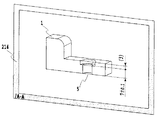
The projected
[0104]
《Setting multiple projections》
Further, a plurality of attribute arrangement planes that have the same shape of the
[0105]
FIG. 18 shows a plurality of attribute arrangement planes 215 and 216 in the same viewing direction, and the same plurality of
[0106]
In addition, when setting multiple attribute placement planes, set attribute placement planes to be associated with each type of attribute information, such as attribute information related to hole position and shape, or attribute information related to secondary processing such as printing and painting. It can also be handled.
[0107]
<Allocation of attribute information>
In order to express the 3D model and the attribute information added to the 3D model as a two-dimensional drawing on the display screen in an easy-to-understand manner, the operator selects or groups a plurality of attribute information of the part of the 3D model to be expressed as appropriate. Associate with a plane. In the case of a two-dimensional drawing representation method, the position of the attribute information may be arranged directly in the projection direction of the related projection view, that is, the region in the view line-of-sight direction. In the so-called “3D drawing”, it is necessary to devise in order to take full advantage of the 3D model.
[0108]
One of the merits of the 3D model is that it can be represented three-dimensionally in a form close to the real thing on the display screen, so the operator who creates the 3D model or the operator of the next process using the 3D model (process designer, mold design / For example, a manufacturer, a measurer, etc.) can eliminate the conversion work from 2D to 3D (this was mainly done in the operator's head), which is necessary when handling 2D drawings. This conversion work often depends on the ability of the operator. In this conversion work, there is a possibility that forgery due to erroneous conversion or loss of conversion time may occur.
[0109]
In the 3D drawing, it is necessary to devise display of attribute information (arrangement of attribute information) at the time of stereoscopic display so as not to impair the three-dimensional representation that is a merit of the 3D model.
[0110]
The point to devise is demonstrated using FIG. 20 (a)-(d).
The first contrivance is about the surface on which attribute information is arranged.
20A is a perspective view of the
[0111]
First, an attribute arrangement plane (not shown), a projection shape 22, and attribute information are input to the
[0112]
Regarding the input of the attribute information, if the planes on which the plurality of attribute information are arranged are staggered as shown in FIG. 20C, the attribute information overlaps and it is difficult to determine the contents of the attribute information. Since it is difficult to see even with a small amount of attribute information as shown in FIG. 20C, it can be easily imagined that if the shape is more complicated, the attribute information is no longer useful information and can no longer hold as a drawing in a perspective state.
[0113]
However, by arranging the attribute information in the same plane as the projection shape 22 as shown in FIG. 20D, the attribute information does not overlap with each other and is equivalent to the representation of the two-dimensional drawing (FIG. 20B). In addition, the attribute information can be easily identified.
[0114]
By doing this, in the drawing form (3D drawing) for adding attribute information to the
[0115]
The same applies to the case where attribute information is associated with a plurality of attribute arrangement planes in the same line-of-sight direction.
[0116]
Further, when creating a plurality of attribute arrangement planes in the same line-of-sight direction, it is preferable to arrange them apart (FIG. 18). When simultaneously displaying the plurality of attribute arrangement planes, the projection shape projected on each attribute arrangement plane, and the attribute information associated with each attribute arrangement plane, each attribute information is created by creating the attribute arrangement plane at the same position. Therefore, even if the viewing direction is shifted as well as the viewing direction, the attribute information overlaps and is difficult to see. In the first place, since there is a lot of attribute information when viewed from the same direction, the attribute information is divided into a plurality of attribute arrangement planes. When attribute information is displayed at the same time, it is inevitable that the attribute information overlaps.
[0117]
Even if it is difficult to see that it is difficult to see from the line of sight, it is effective to dispose the projected shapes in the same line of sight as a means in order to make it easy to determine the attribute information in a perspective state.
[0118]
The second device is how to extract attribute information.
In order to extract the attribute information from the 3D model to the attribute arrangement plane on which the projection shape in the three-dimensional space is arranged, it is necessary to fold the line corresponding to the lead line or the dimension extension line once, for example, and draw it into an L shape. is there. As a drawing method, as shown in FIG. 21, a method of bending on the 3D model 31 side (firstly, attribute information is extracted from the 3D model 31 and an attribute arrangement plane in which a
[0119]
"magnification"
Next, the magnification of the attribute arrangement plane will be described. The scaling factor is a scaling factor when the 3D model shape, projection shape, and attribute information in the (virtual) three-dimensional space are displayed on the
[0120]
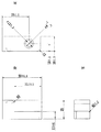
FIGS. 22A, 22 </ b> B, and 22 </ b> C are diagrams illustrating a state in which a part of the
In this embodiment, the present invention is effective for all 3D-CAD regardless of the hardware constituting the 3D-CAD apparatus or the method of configuring the 3D shape model.
[0121]
Furthermore, the size of the attribute information (character or symbol height) associated with the attribute arrangement plane (not shown) is changed according to the magnification associated with the attribute arrangement plane. (Fig. 22 (b))
The size of the attribute information (the unit is mm, for example) is defined as the size in the virtual three-dimensional space where the
[0122]
For example, the size of the attribute information when the magnification is 1 on the attribute arrangement plane is 3 mm. FIG. 22C shows an example in which the attribute arrangement plane is displayed with a magnification of 5 and a character height of 3 mm. Since the attribute information associated with the attribute arrangement plane is displayed at a display magnification of 5 times, its size is 15 mm. For viewing, it is good that the displayed size is large, but 15 mm is larger than necessary, and it is not preferable when there is a lot of information to be viewed at a time.
[0123]
22B and 22C, a square line indicates a displayable range on the
If the attribute information is arranged so as not to overlap, the position of the attribute information is separated from the 3D model and the projection shape, so the relationship between the shape and the attribute information related thereto is difficult to understand and the possibility of misreading also occurs. Further, if there is a large amount of attribute information to be displayed, all the attribute information cannot be displayed on the
[0124]
If the character size is not changed when the image is to be displayed in a reduced size (magnification is less than 1), the display size of the attribute information on the
[0125]
Therefore, in consideration of the time when the attribute information is displayed, it is desirable to change the size of the attribute information information according to the magnification.
[0126]
Therefore, the magnification and the size of the attribute information should be approximately inversely related. For example, when the magnification of the attribute placement plane is 1, and the size of the attribute information is set to 3 mm, if the view magnification of the
[0127]
In addition, when attribute information associated with an arbitrary attribute arrangement plane is associated with another attribute arrangement plane, the size of the attribute information is changed according to the magnification of the attribute arrangement plane to be changed.
[0128]
《Multiple selection of projections》
In the above embodiment, when displaying the attribute information associated with the attribute arrangement plane, the number of attribute arrangement planes to be selected is only one. However, in view of the object of the present invention, a plurality of attribute arrangement planes are displayed. There is no problem even if you choose.
[0129]
However, when performing single selection of the attribute arrangement plane, since there is only one line-of-sight direction, magnification, and line-of-sight center, there is only one display method on the display device, but when multiple selections are made, there are multiple display methods. It must be devised. For example, when multiple selections are made, all the attribute information associated with the selected attribute arrangement plane is displayed, and it is possible to select which attribute arrangement plane is adopted for the line-of-sight direction, magnification, and line-of-sight center. It is possible.
[0130]
In addition, the display of the attribute information is devised so that the group can be easily identified by changing the color for each related attribute arrangement plane.
[0131]
<< Display method of attribute information >>
In the above conventional example, as the order of selectively displaying the attribute information input to the 3D model, the attribute arrangement plane is first selected, and then the attribute information associated with the attribute arrangement plane is appropriately displayed. In this order, the description is not limited to this method. The attribute information is selected, and then the line-of-sight direction, magnification, and line-of-sight center of the attribute arrangement plane with which the attribute information is associated. A technique for displaying a 3D model, a projection shape, and its attribute information is also effective.
[0132]
FIG. 23 is a flowchart showing this series of processing operations.
As shown in FIG. 9, the attribute information (for example, 35 ±) is displayed in a state where the
[0133]
By this selection, the
As a result, the relationship between the selected attribute information and the
[0134]
In addition, the geometric information (ridge line, face, vertex) of the 3D model is selected, the attribute information associated with the geometric information is displayed, and the line-of-sight direction, magnification, It is also effective to display a 3D model, a projection shape and its attribute information at the center of the line of sight.
[0135]
FIG. 24 (display from attribute information selection) is a flowchart showing this series of processing operations.
The geometric information of the 3D model is selected (step S321).
The attribute information associated with the selected geometric information is displayed (step S322).
If there is a plurality of associated attribute information, all of them may be displayed. Further, all attribute information belonging to the attribute arrangement plane with which the attribute information is associated may be displayed.
[0136]
Next, the 3D model, the projection shape, and the attribute information are displayed based on the line-of-sight direction, the magnification, and the line-of-sight center of the attribute arrangement plane related to the displayed attribute information.
In this way, the related attribute information can be searched and displayed from the geometric information of the 3D model, so it is very easy to use.
[0137]
"display"
Here, the display of the 3D model to which the attribute information created as described above is added will be described.
[0138]
The 3D model to which the attribute information created by the information processing device shown in FIG. 2 is added can be obtained by transferring the data of the created device itself or the 3D model created via the external connection device, to the other similar items. Using the information processing apparatus, it can be displayed and used in each step shown in FIG.
[0139]
First, a 3D model created by a product / unit / part design engineer or an operator who is a design designer is shown in FIGS. 10A, 10B, and 10C. By performing the display, new attribute information can be added to the 3D model as if a two-dimensional drawing was created. In addition, for example, when the shape is complicated, desired attribute information can be efficiently and accurately displayed by alternately displaying a 3D model and a two-dimensional display alternately or on the same screen as necessary. Can be entered.
[0140]
Further, an operator who is in a position to check / approve the created 3D model displays the created 3D model in the same screen or by switching the display shown in FIGS. 10 (a), (b), and (c). , A check, OK, NG, hold, and mark, symbol, or attribute information such as coloring is added, which means “requires examination”. It goes without saying that a check is performed while comparing and referring to a plurality of products / units / parts as necessary.
[0141]
Further, it can be used when a design engineer or design designer other than the creator of the created 3D model designs other products / units / parts by referring to the created 3D model. By referring to this 3D model, the creator's intention or design method can be easily understood.
[0142]
Further, when a 3D model is manufactured and manufactured, an operator who gives information necessary for the 3D model or attribute information can be used. In this case, the operator is an engineer who sets the production process of the product / unit / part. The operator adds, for example, instructions on the type of machining process, tools to be used, etc., or corners R and chamfers on ridges, corners, corners, etc. necessary for machining to the 3D model. Alternatively, a measurement method instruction with respect to dimensions, dimension tolerances, etc., addition of measurement points to the 3D model, information to be taken into account in measurement, etc. are input. These are performed efficiently and reliably while viewing the display that is arranged and created as shown in FIGS. 10A, 10B, and 10C, and confirming the shape three-dimensionally as necessary.
[0143]
In producing and manufacturing a 3D model, an operator who obtains information necessary for making a desired preparation from the 3D model or attribute information can be used. In this case, the operator is a design engineer who designs dies, jigs, various devices, etc. necessary for production and manufacture. The operator understands and grasps the shape while viewing the 3D model in a three-dimensional state, and checks and extracts the necessary attribute information with a display that is arranged and created as shown in FIGS. 10 (a), (b), and (c). I will do it. Based on the attribute information, the operator designs a mold, a tool, various devices, and the like. For example, if the operator is a mold design engineer, the operator designs from the 3D model and attribute information while examining the mold configuration and structure. If necessary, corners R and chamfers are added to ridges, corners, corners, and the like necessary for mold production. When the mold is a resin injection mold, the operator adds a draft necessary for molding to the 3D model, for example.
[0144]
It can also be used by operators who produce and manufacture products / units / parts. In this case, the operator is a product / unit / part processing engineer or assembly engineer. The operator can easily understand and grasp the shape to be processed or the shape to be assembled while viewing the 3D model in a three-dimensional state, and has been arranged and created as shown in FIGS. 10 (a), 10 (b), and 10 (c). Look at the display and perform processing and assembly. Then, if necessary, the operator checks the shape of the processing part and the assembly part. Further, the processed, difficult processing, or processing result may be added as attribute information to the 3D model or already added attribute information, and the information may be fed back to the design engineer.
[0145]
Further, it can be used by an operator who inspects, measures, and evaluates a manufactured / manufactured product / unit / part. In this case, the operator is an engineer who inspects, measures, and evaluates a product / unit / part. The operator looks at the display created and arranged as shown in FIGS. 10 (a), 10 (b), and 10 (c) with respect to the measurement method, measurement point, and information to be taken into consideration for the above dimensions and dimensional tolerances. Moreover, while checking the shape three-dimensionally as necessary, it is obtained efficiently and reliably, and inspection, measurement and evaluation are executed. Then, the operator can give inspection, measurement, and evaluation as attribute information to the 3D model as necessary. For example, a measurement result corresponding to the dimension is given. In addition, a mark or a symbol or the like is given to the attribute information of a defective portion such as a dimensional tolerance or a defect, or a 3D model. Further, in the same manner as the check result, inspection, measurement, evaluated marks, symbols, coloring, or the like may be performed.
[0146]
Further, it can be used by operators in various departments and roles related to production / manufacture of products / units / parts. In this case, the operator creates, for example, a person in charge of manufacturing and manufacturing cost analysis, a person in charge of ordering a product / unit / part itself, various related parts, a product / unit / part manual, a packing material, and the like. The person in charge, etc. In this case as well, the operator can easily understand and grasp the shape of the product / unit / part while viewing the 3D model in a three-dimensional state, and the layout is created as shown in FIGS. 10 (a), 10 (b), and 10 (c). See various displays and perform various tasks efficiently.
[0147]
<Entering inspection instructions>
Next, inspection instructions will be described.
As described above, in order to inspect the finished mold, parts, etc., the dimensions are assigned to the 3D model and displayed in advance.
[0148]
Here, the attribute information is input so that the inspection position becomes clear with respect to the set attribute arrangement plane.
[0149]
That is, the inspection order, inspection position, inspection item, and the like are input for the surfaces, lines, ridge lines, and the like constituting the 3D model. And the inspection man-hour is reduced by inspecting in that order.
[0150]
First, the whole is input by inputting the item to be inspected and the position. Next, the inspection order is assigned by a predetermined method, and the order is assigned to each item. When actually inspecting, the attribute arrangement plane is selected by instructing the order, and in the displayed attribute arrangement plane, the surface of the position to be inspected is different from other forms (colors, etc.) Is different) and the inspection position becomes clear.
Then, for each inspected inspection item, the inspection result is input, and it is determined whether or not reshaping is necessary.
[0151]
As described above, according to the embodiment of the present invention, an easy-to-see screen can be obtained with a simple operation using the set attribute arrangement plane and attribute information. In addition, the relationship between the line-of-sight direction and the attribute information can be found in a list. Furthermore, since a dimension value or the like is input in advance, misreading due to an operation mistake by an operator is reduced.
[0152]
In addition, only information associated with the attribute arrangement plane can be seen, so that necessary information can be easily known.
[0153]
Further, by assigning a large amount of attribute information in the same line-of-sight direction to a plurality of attribute arrangement planes, an easy-to-view screen can be obtained and necessary information can be easily known.
[0154]
In addition, attribute information can be displayed in an easy-to-understand manner by setting an attribute arrangement plane in the 3D model, that is, in a cross-sectional position.
[0155]
Further, since the size of the attribute information is changed according to the display magnification of the attribute arrangement plane, it is easy to understand and can be expressed appropriately.
[0156]
Further, by arranging the attribute information and the projection shape on the attribute arrangement plane, the attribute information can be read even if a three-dimensional representation of the 3D model viewed from an oblique direction is performed.
[0157]
Furthermore, by creating 2D graphics or text information on the attribute arrangement plane, it is possible to express and display appropriately more easily.
[0158]
In addition, from the attribute information, it is possible to search only the attribute arrangement plane and only information associated with the attribute arrangement plane, and easily know necessary information.
[0159]
Further, from the geometric information, the attribute information and the attribute arrangement plane can be searched, and only the information associated with the attribute arrangement plane can be viewed, so that necessary information can be easily known.
[0160]
【The invention's effect】
As described above, according to the present invention, attribute information can be input and arranged on a desired virtual plane, and a projection shape in which a 3D model is projected on the virtual plane is created, regardless of the number of attribute information. Information can be input very easily, and information can be transmitted clearly and clearly.
[0162]
Further, according to the present invention, it is possible to efficiently use the 3D model, the attribute information, the 2D figure on the virtual plane, and the text information without creating a so-called two-dimensional drawing representing the shape two-dimensionally from the shape data of the 3D model. Can communicate design information well.
[Brief description of the drawings]
FIG. 1 is a diagram showing an overall flow of mold part mold production according to an embodiment of the present invention.
FIG. 2 is a block diagram of a CAD apparatus according to an embodiment of the present invention.
FIG. 3 is a flowchart showing processing operations of the CAD apparatus shown in FIG. 2;
4A and 4B are diagrams showing examples of a shape model according to an embodiment of the present invention, in which FIG. 4A is a diagram of SolidModel, and FIG. 4B is a diagram of Shell;
FIG. 5 is a conceptual diagram showing the relationship between the respective parts constituting the shape model of the embodiment of the present invention.
FIG. 6 is a conceptual diagram illustrating a method for storing Face information on the
FIG. 7 is a diagram showing a 3D model, an attribute arrangement plane, and a projection shape according to the embodiment of the present invention.
FIG. 8 is a diagram illustrating a 3D model, an attribute arrangement plane of a cross section, and a projection shape according to an embodiment of the present invention.
FIG. 9 is a diagram showing a 3D model, an attribute arrangement plane, a projection shape, and attribute information according to the embodiment of the present invention.
10A and 10B are diagrams illustrating a 3D model and attribute information viewed from each attribute arrangement plane according to the embodiment of the present invention, in which FIG. 10A is a 3D model and attribute information viewed from the line-of-sight direction of the plan view, and FIG. FIG. 3C is a diagram illustrating the 3D model and attribute information viewed from the line-of-sight direction in the figure, and FIG.
FIG. 11 is a diagram illustrating a 3D model, an attribute arrangement plane, and attribute information according to the embodiment of this invention.
FIG. 12 is a flowchart showing a processing operation when attribute information is added to the 3D model according to the embodiment of the present invention.
FIG. 13 is a flowchart showing a processing operation when attribute information is added to the 3D model according to the embodiment of the present invention.
FIG. 14 is a flowchart showing a processing operation when attribute information is added to the 3D model according to the embodiment of the present invention.
FIG. 15 is a flowchart showing a processing operation when attribute information is added to the 3D model according to the embodiment of the present invention.
FIG. 16 is a flowchart when displaying a 3D model to which attribute information is added according to the embodiment of the present invention;
FIG. 17 is a diagram showing a 3D model, an attribute arrangement plane of a cross section, a projection shape, and attribute information according to the embodiment of the present invention.
FIG. 18 is a diagram showing a state in which a plurality of attribute arrangement planes and projection shapes are set in the 3D model according to the embodiment of the present invention.
FIG. 19 is a diagram showing a 3D model, a projection shape, and attribute information according to the embodiment of the present invention.
20A and 20B are diagrams illustrating an example of a 3D model according to an embodiment of the present invention, in which FIG. 20A is a perspective view of the 3D model, FIG. 20B is a plan view of the 3D model, and FIG. The perspective view explaining the state which added information, (d) shows the perspective view performed by devising arrangement | positioning of attribute information.
FIG. 21 is an explanatory diagram of how to extract attribute information according to the embodiment of this invention.
FIG. 22 is a diagram showing a case where an attribute arrangement plane is assigned to a part of the 3D model according to the embodiment of the present invention, where (a) is a diagram of the 3D model, and (b) is a figure showing stepped shapes and attribute information; FIG. 8C is a diagram showing an easy display, and FIG. 8C is a diagram showing an example in which a projected view is displayed with a view of
FIG. 23 is a flowchart when displaying a 3D model and attribute information from the attribute information according to the embodiment of the present invention;
FIG. 24 is a flowchart for displaying a 3D model and attribute information from geometric information according to the embodiment of the present invention.
FIG. 25 is a diagram illustrating an example of a conventional 3D model.
26A and 26B are diagrams of the 3D model shown in FIG. 25, in which FIG. 26A is a plan view, FIG. 26B is a side view, and FIG. 26C is a front view.
27 is a diagram showing a state in which attribute information is added to the conventional 3D model shown in FIG.
[Explanation of symbols]
1, 21, 31, 41, 51 3D model
2, 3, 4, 5, 6, 7, 22, 32 Projection
11, 12 dimension extension line
32 Projection
201 Internal storage device
201a front
201b upper surface
201c side
202 External storage device
203 CPU device
204 Display device
205 Input device
206 Output device
207 External connection device
211, 212, 213, 214, 215, 216 Attribute arrangement plane
Claims (1)
前記3Dモデルおよび前記仮想的な平面が配置される三次元空間内において、前記3Dモデルと前記仮想的な平面上の前記3Dモデルの投影形状とを結ぶ引出し線を前記視線方向に表示する表示手段とを備え、
前記表示手段は、前記3Dモデルの投影形状から前記仮想的な平面上に前記属性情報を引き出して表示し、前記投影形状と前記属性情報とを同一面上に配置する
ことを特徴とする情報処理装置。Projecting means for projecting a 3D model onto a virtual plane to which attribute information for the 3D model is associated , wherein the association is such that the attribute information is on the virtual plane so as to face the direction of the line of sight of the virtual plane. Assigned projection means ;
Display means for displaying a leader line connecting the 3D model and the projected shape of the 3D model on the virtual plane in the visual line direction in a three-dimensional space in which the 3D model and the virtual plane are arranged. And
The display means extracts and displays the attribute information on the virtual plane from the projection shape of the 3D model, and arranges the projection shape and the attribute information on the same plane. apparatus.
Priority Applications (2)
| Application Number | Priority Date | Filing Date | Title |
|---|---|---|---|
| JP2002136193A JP3937913B2 (en) | 2002-05-10 | 2002-05-10 | Information processing device |
| US10/430,213 US20030210244A1 (en) | 2002-05-10 | 2003-05-07 | Information processing apparatus and method |
Applications Claiming Priority (1)
| Application Number | Priority Date | Filing Date | Title |
|---|---|---|---|
| JP2002136193A JP3937913B2 (en) | 2002-05-10 | 2002-05-10 | Information processing device |
Publications (3)
| Publication Number | Publication Date |
|---|---|
| JP2003330970A JP2003330970A (en) | 2003-11-21 |
| JP2003330970A5 JP2003330970A5 (en) | 2005-09-29 |
| JP3937913B2 true JP3937913B2 (en) | 2007-06-27 |
Family
ID=29698303
Family Applications (1)
| Application Number | Title | Priority Date | Filing Date |
|---|---|---|---|
| JP2002136193A Expired - Fee Related JP3937913B2 (en) | 2002-05-10 | 2002-05-10 | Information processing device |
Country Status (1)
| Country | Link |
|---|---|
| JP (1) | JP3937913B2 (en) |
Families Citing this family (4)
| Publication number | Priority date | Publication date | Assignee | Title |
|---|---|---|---|---|
| JP4616585B2 (en) * | 2004-06-30 | 2011-01-19 | 富士通株式会社 | Image display device and image display program |
| JP4992439B2 (en) * | 2007-01-26 | 2012-08-08 | 富士通株式会社 | CAD system projection method, CAD system projection program, and CAD system |
| JP6467879B2 (en) | 2014-11-11 | 2019-02-13 | 富士通株式会社 | Leader line layout position determining program, leader line layout position determining method, and leader line layout position determining apparatus |
| JP2018045587A (en) * | 2016-09-16 | 2018-03-22 | 株式会社トプコン | Image processing device, image processing method, and image processing program |
-
2002
- 2002-05-10 JP JP2002136193A patent/JP3937913B2/en not_active Expired - Fee Related
Also Published As
| Publication number | Publication date |
|---|---|
| JP2003330970A (en) | 2003-11-21 |
Similar Documents
| Publication | Publication Date | Title |
|---|---|---|
| US7119805B2 (en) | Three-dimensional CAD attribute information presentation | |
| US7127324B2 (en) | Information processing apparatus and information processing method | |
| US6917842B2 (en) | Information processing apparatus and method | |
| US20030210244A1 (en) | Information processing apparatus and method | |
| JP5143252B2 (en) | Information processing apparatus, method, and program | |
| JP3937913B2 (en) | Information processing device | |
| JP2003330972A (en) | Information processing device and method | |
| JP3825994B2 (en) | Information processing apparatus and method | |
| JP4845289B2 (en) | Information processing apparatus and method | |
| JP3935361B2 (en) | Information processing apparatus and method | |
| JPS62251905A (en) | Interactive graphic input system | |
| JP4846927B2 (en) | Information processing apparatus and method | |
| JP2002324083A (en) | Apparatus and method for information processing | |
| JP2002324085A (en) | Apparatus and method for information processing | |
| JP2006113846A (en) | Information processor and processing method | |
| JP2002324253A (en) | Information processing apparatus and method | |
| JP2004192035A (en) | Information processing device and method | |
| JP3796454B2 (en) | Information processing apparatus, information processing method, and program | |
| JP2002350122A (en) | Apparatus and method for processing attribute information | |
| JP2002324091A (en) | Apparatus and method for information processing | |
| JP2004070415A (en) | Information processing device, method, and program | |
| JP3796453B2 (en) | Information processing apparatus, information processing method, and program | |
| JP2002324247A (en) | Information processor and its method | |
| JP3796452B2 (en) | Information processing apparatus, information processing method, and program | |
| JP2006113657A (en) | Information processor |
Legal Events
| Date | Code | Title | Description |
|---|---|---|---|
| A521 | Written amendment |
Free format text: JAPANESE INTERMEDIATE CODE: A523 Effective date: 20050510 |
|
| A621 | Written request for application examination |
Free format text: JAPANESE INTERMEDIATE CODE: A621 Effective date: 20050510 |
|
| A131 | Notification of reasons for refusal |
Free format text: JAPANESE INTERMEDIATE CODE: A131 Effective date: 20061212 |
|
| A521 | Written amendment |
Free format text: JAPANESE INTERMEDIATE CODE: A523 Effective date: 20070207 |
|
| TRDD | Decision of grant or rejection written | ||
| A01 | Written decision to grant a patent or to grant a registration (utility model) |
Free format text: JAPANESE INTERMEDIATE CODE: A01 Effective date: 20070313 |
|
| A61 | First payment of annual fees (during grant procedure) |
Free format text: JAPANESE INTERMEDIATE CODE: A61 Effective date: 20070319 |
|
| R150 | Certificate of patent or registration of utility model |
Free format text: JAPANESE INTERMEDIATE CODE: R150 |
|
| FPAY | Renewal fee payment (event date is renewal date of database) |
Free format text: PAYMENT UNTIL: 20110406 Year of fee payment: 4 |
|
| FPAY | Renewal fee payment (event date is renewal date of database) |
Free format text: PAYMENT UNTIL: 20130406 Year of fee payment: 6 |
|
| FPAY | Renewal fee payment (event date is renewal date of database) |
Free format text: PAYMENT UNTIL: 20130406 Year of fee payment: 6 |
|
| FPAY | Renewal fee payment (event date is renewal date of database) |
Free format text: PAYMENT UNTIL: 20140406 Year of fee payment: 7 |
|
| LAPS | Cancellation because of no payment of annual fees |