JP3937501B2 - Electronics - Google Patents
Electronics Download PDFInfo
- Publication number
- JP3937501B2 JP3937501B2 JP09752797A JP9752797A JP3937501B2 JP 3937501 B2 JP3937501 B2 JP 3937501B2 JP 09752797 A JP09752797 A JP 09752797A JP 9752797 A JP9752797 A JP 9752797A JP 3937501 B2 JP3937501 B2 JP 3937501B2
- Authority
- JP
- Japan
- Prior art keywords
- cam
- shaft
- display body
- cam groove
- electronic device
- Prior art date
- Legal status (The legal status is an assumption and is not a legal conclusion. Google has not performed a legal analysis and makes no representation as to the accuracy of the status listed.)
- Expired - Fee Related
Links
Images


Description
【0001】
【発明の属する技術分野】
本発明は、例えば外付け式の液晶表示パネルを備えたビデオカメラ装置等に適用して好適な電子機器に関し、詳しくはビデオカメラ本体部に対して液晶表示パネルを回動起立させ、さらに旋回動作させるためのヒンジ機構を超小型化することによって、装置全体のコンパクト化を図ることができるようにしたものである。
【0002】
【従来の技術】
従来、この種の液晶表示パネルを備えたビデオカメラ装置の一例として、本出願人が先に特願平6−281522号で提案したビデオカメラがある。これを図12を参照して説明する。
【0003】
図12において、全体を符号60で示したビデオカメラ本体部の一側面に液晶表示パネル61が配置されている。この液晶表示パネル61はビデオカメラ本体部60とヒンジ機構部62によって結合され、パネル表示面を裏側にしてビデオカメラ本体部60に形成した収納部60aに収納されている。尚、63はビデオカメラ本体部1に搭載した電子ビューファインダーである。
【0004】
このように構成した液晶表示パネル61は図13に示すようにヒンジ機構部62を回動支点として直立位置に起立回動した状態において、液晶表示パネル61のパネル表示面61aに映し出される画像を見ながらビデオ撮影することができる。
【0005】
また、液晶表示パネル61は図13の状態からヒンジ機構部62を回動中心として180°反転動作することができ、従って、この状態ではパネル表示面61aが撮影側を向くので被撮影者に撮影画像を見せながらビデオ撮影をすることができる。
【0006】
さらに、液晶表示パネル61を反転した状態のまま、つまりパネル表示面61aを表側にした状態でビデオカメラ本体部60の収納部60aに収納して使用することで、ビデオ再生画像を液晶表示パネル61に映し出して見ることもできる。
【0007】
上述のように構成したビデオカメラ装置は、液晶表示パネルの視認性を高めビデオカメラの様々な使用態様に対応することができるようにした新規なビデオカメラ装置となる。
【0008】
【発明が解決しようとする課題】
しかし、液晶表示パネル61を起立回動したり反転動作するためのヒンジ機構部62については改善する余地もある。ヒンジ機構部62は液晶表示パネル61を直立位置と収納位置とに回動動作するための第1の回動機構と、液晶表示パネル61を直立位置状態において反転し旋回動作するための第2の回動機構とを有する、いわゆる2軸ヒンジ機構から構成されている。
【0009】
この2軸ヒンジ機構には液晶表示パネル61が収納位置及び直立位置に起立動作した状態において旋回動作可能とされ、また、液晶表示パネル61が上述した収納位置及び直立位置に起立動作する以外の途中の動作状態では旋回不能にするためのカム部材が配置されている。
【0010】
このカム部材は板金を曲げ加工して成形したものであるため比較的大きな部品となり、2軸ヒンジ機構全体のサイズが大きくならざるを得ない。従って、ビデオカメラ装置の奥行き長さを短くした場合には、液晶表示パネルの画面サイズを小さくしなければならなかったり、また、2軸ヒンジ機構の高さが大きくなることからビデオカメラ装置の幅方向のサイズが必然的に厚くなるといった問題がある。
【0011】
また、上述したカム部材はビデオカメラ本体部側に別部材であるブラケットを介して取り付ける必要があり、また、カム部材と係合する回転軸の先端部に別に対向する両側部が偏平な部品が必要となる等、部品点数が多くなりその分、コストアップとなるといった問題もある。
【0012】
本発明は、上述したような課題を解消するためになされたもので、2軸ヒンジ機構の超小型化と共に部品点数の削減を図ることができ、その分、他の構成部材の設計自由度を向上できるようにし、ビデオカメラ装置等の液晶表示パネルの2軸ヒンジ機構に適用して好適な電子機器を得ることを目的とする。
【0013】
【課題を解決するための手段】
上述の目的を達成するため、本発明による電子機器は、表示体を収納状態から起立回動させる第1の回動手段と、この第1の回動手段に回転軸を中心として表示体を旋回動作させる第2の回動手段とからなる2軸ヒンジ機構を備え、第2の回動手段の回転軸先端部のカム軸を、第1の回動手段のブラケットに形成したカム溝に係合させる。更に、2軸ヒンジ機構は、カム軸が回転軸の先端部を加工した偏平軸形状であり、カム溝はその両端側ではカム軸が回転可能な拡開したカム溝形状であり、カム溝の途中ではカム軸の偏平軸側が通過する幅を有する通路状カム形状であって、ブラケットは一対の軸受板とその軸受板を連結する連結フレームとからなり、カム溝は連結フレームと一体にその連結フレームの一部として構成されており、軸受板にはそれぞれ軸受孔を有し、その軸受孔に可動フレームが軸受されてなるようにしたものである。
【0014】
このように構成したことで、表示体が収納及び直立位置ではカム軸がカム溝内を旋回動作可能となり、表示体が収納及び直立位置以外の途中の回動位置ではカム軸がカム溝に規制され旋回不能となる。
【0015】
【発明の実施の形態】
以下、本発明による電子機器の実施の形態を液晶表示パネルを有するビデオカメラ装置を例にとって図面を参照して説明する。
【0016】
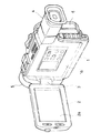
図1は本例によるビデオカメラ装置で液晶表示パネルの使用しない状態の外観斜視図である。
【0017】
図1において、電子機器本体であるビデオカメラ本体部1の一側面に表示体である液晶表示パネル2が配置されている。この液晶表示パネル2は、ビデオカメラ本体部1と2軸ヒンジ機構部3によって結合され、パネル表示面を裏側にしてビデオカメラ本体部1に形成した表示体収納部である収納部1aに収納されている。尚、4は、ビデオカメラ本体部1に搭載した電子ビューファインダーであり、5は、カメラ機構部の前玉レンズ、6は、電源であるバッテリーである。
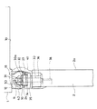
【0018】
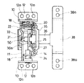
図2はビデオカメラ本体部1と液晶表示パネル2が2軸ヒンジ機構部3で結合されている構成図であり、図3は2軸ヒンジ機構部3の分解斜視図、図4は2軸ヒンジ機構部3の組立て状態の平面図、図5は同じく組み立て状態の正面図である。
【0019】
2軸ヒンジ機構部3の詳細について説明する。
軸受板となる一対の第1のブラケット10,10間に連結フレームであるフレーム11がその両端部の爪部11a,11a(一方側のみが見えている)をカシメ固定して連結されている。両ブラケット10,10に取付板12,12を有している。両ブラケット10,10には軸受孔13,13を有し、この軸受孔13,13にコ字形状の可動フレーム14が軸受けされる。
【0020】
一方のブラケット10の内面にはトルク発生座がね15が取り付けられる。このトルク発生座がね15は切欠孔16,16及び内周側に短く突出する複数の突起17を有し、切欠孔16,16をブラケット10から突出する凸面10a,10aに嵌合し、中心の軸孔15aを軸受孔13に通じるようにして固定している。そして、このトルク発生座がね15に可動フレーム14の一方の軸受片18が位置決めされ、この軸受片18の内面側にワッシャ19、2枚の波形ワッシャ20,20及びワッシャ21を重ね、これらの各軸孔21a,20a,20a,19aに軸ピン22を貫通し、さらに、可動フレーム14の一方の軸受片18の軸孔18a、トルク発生座がね15の軸孔15a、ブラケット10の軸受孔13を通し、軸ピン22の端部をカシメ固定している。この際、可動フレーム14の軸受片18の周囲に形成した複数の切欠孔18bがトルク発生座がね15の各突起17と対応するようにさせている。
【0021】
他方のブラケット10の軸受孔13には、その内面側から鍔部23の外側のカシメ軸24aがカシメ固定され、鍔部23の内側に突出する軸ピン24に可動フレーム14の他方の軸受片18の軸孔18aが軸受けされる。
【0022】
このように可動フレーム14は上述した軸受け構造によりブラケット10,10に対し軸ピン22,24を中心として回動する第1の回動機構を構成している。
【0023】
一方、可動フレーム14の内面側中央部にはばね受け25が配置され、ばね受け25の上部に形成した凹部25aが可動フレーム14のフランジ26に位置決めされ保持されている。このばね受け25には略アーチ形のトルク発生板ばね27がその両端部の脚部27a,27aを可動フレーム14の溝孔28,28に係合し取り付けられる。このトルク発生板ばね27の上下中心部に凸部29,29が設けられている。
【0024】
符号30は上述した可動フレーム14に軸受けされる回転軸であり、この回転軸30にはフランジ30aの前部に先端部が縦型に偏平に加工されたカム軸31が形成されている。フランジ30aの後部は横型に偏平に加工され、カム軸31より太くされた軸部32に設けられている。この軸部32にはクリック発生ワッシャ33が回転不能に挿入可能であり、クリック発生ワッシャ33の周囲には上下,左右方向に4つの溝部34と、斜め位置に1つのストッパ部34aが形成されている。
【0025】
かくして、回転軸30の軸部32にクリック発生ワッシャ33の角孔33aが挿入されて回転不能にされ、この軸部32を上述したトルク発生ばね27の窓孔27b及びばね受け25の開口孔25bを通して可動フレーム14の開口孔14aを貫通している。
【0026】
そして、可動フレーム14の開口孔14aを貫通した軸部32は、可動フレーム14の背面側に配置された樹脂モールド部材から成形されたカバー取付枠体35の軸受筒部36に軸受けされ、このカバー取付枠体35はその内面側から突出した凸部35a,35aを可動フレーム14の位置決め孔14b,14bに位置決めされ、カバー取付枠体35の通し孔35c,35cから挿入したねじ37,37を可動フレーム14のねじ孔14c,14cにねじ止めして固定される。
【0027】
また、カバー取付枠体35の軸受筒部36から突き出る軸部32のカシメ軸32aに後述する液晶表示パネルを支持するための第2のブラケット38に形成したフランジ39の取付孔39aがカシメ固定される。
【0028】
このように可動フレーム14には回転軸30と共に第2のブラケット38が旋回動作される第2の回転機構を構成している。
【0029】
ここで、上述した第1の回動機構及び第2の回動機構は合体式の上カバー40及び下カバー41により第1のブラケット10,10以外が保護される。上カバー40には4つの脚片42(図3では2つの脚片のみが見えている)が延び、先端部に係合爪42aが形成されている。この上カバー40がその内面に形成した図示しない凸部をカバー取付枠体35の係合孔35d,35dに係合して位置決めされる。
【0030】
下カバー41にはその内面にピン43,43が形成され、このピン43,43がカバー取付枠体35の係合孔44,44に係合され位置決めされる。
【0031】
上カバー40及び下カバー41の位置決め状態において、両カバーを合体すると、上カバー40の各係合爪42aが下カバー41の係合部45に係合され一体化させることができる。また、両カバー40,41にはそれぞれ半割状の筒カバー46,47を有し、両カバーの合体状態においてカバー取付枠体35の軸受筒部36が筒カバー46,47で保護される。
【0032】
尚、図3においてカバー取付枠体35の下面に突出する一対の係合爪48,48は、図示しない電源オン/オフ用のマイクロスイッチ体を固定するためのものであり、本発明の要部ではないためここでは省略する。また、筒カバー46,47の外縁部には液晶表示パネルに内蔵した液晶表示画像の上下を反転動作するためのカム面49,49が形成されている。
【0033】
さて、上述のように構成した2軸ヒンジ機構において、第2の回動機構の先端部のカム軸31は前述した第1のブラケット10,10を連結しているフレーム11に対応している。フレーム11は第1の回動機構の回動中心、すなわち、第1のブラケット10の軸受孔13を中心とする円弧面形状を有し、このフレーム11の内面にカム溝50が設けられている。カム溝50は上下両端部ではカム軸31が自由に回動可能なような半円形状の第1のカム溝51a及び第2のカム溝51bであり、この両カム溝51a,51bの間はカム軸31の偏平部分が通過する幅を有する通路状カム溝51cとなっている。
【0034】
上述したように構成した2軸ヒンジ機構は、第1のブラケット10,10をビデオカメラ本体部1に取付板12,12のねじ孔12aを利用してねじ固定され、また、第2のブラケット38に液晶表示パネル2がねじ孔38aを利用してねじ固定される。
【0035】
次に、2軸ヒンジ機構の動作を図6に示したカム溝50の展開図を含めて説明する。
【0036】
図1及び図2は液晶表示パネル2のパネル表示面2a側が内側にされてビデオカメラ本体部1の収納部1a内に収納されている状態である。
【0037】
液晶表示パネル2の収納状態では、第2の回動機構の先端部のカム軸31は第1のカム溝51a内に実線で示した向きで位置している。従って、カム軸31は第1のカム溝51a内において第2の回動機構を中心として液晶表示パネル2は旋回動作可能であるが、液晶表示パネル2が収納部1a内に収納されている状態であるので旋回動作する必要もない。
【0038】
図7及び図8は液晶表示パネル2を直立位置に起立回動させ、パネル表示面2aに映し出される画像を見ながらビデオ撮影を可能にしている状態である。すなわち、液晶表示パネル2は第1の回動機構を回動支点として起立回動すると、第2の回動機構のカム軸31が第1のカム溝51aから通路状カム溝51cを通過して第2のカム溝51b内に移動することになる。このため、液晶表示パネル2が完全に起立しない途中の回動位置では、カム軸31が通路状カム溝51cに位置しているため第2の回動機構の回動が阻止され、液晶表示パネル2の旋回動作は不能となる。また、第1の回動機構の回動動作ではトルク発生座がね15及び波形ワッシャ20の作用により所定のトルクが発生し、液晶表示パネル2の起立回動に手応えのある動作を可能にしている。
【0039】
図9は液晶表示パネル2を直立位置から180°旋回動作させ、パネル表示面2aに映し出される画像を被撮影者に見せながらビデオ撮影を可能にしている状態である。すなわち、液晶表示パネル2の直立位置ではカム軸31が第2のカム溝51b内に位置している状態であるので、第2の回動機構が回転軸30を中心として回動可能となり液晶表示パネル2の旋回動作が行える。この際、液晶表示パネル2の旋回動作はクリック発生ワッシャ33の溝部34とクリック発生板ばね27の凸部29とがばね係合していることから90°の旋回動作毎にクリック作用し確実性と共に手応えのある旋回動作が可能となる。
【0040】
また、液晶表示パネル2の旋回方向は上向き方向に旋回動作させることで180°の旋回が可能となり、180°を僅かに越えた旋回角度においてクリック発生ワッシャ33に形成したストッパ部34aが可動フレーム14のフランジ26に突き当たり停止するように規制されている。また、下向きに旋回した場合では、クリック発生ワッシャ33のストッパ部34aが可動フレーム14のフランジ26に突き当たり下向き状態で停止するように規制されている。
【0041】
かくして、液晶表示パネル2は図9に示した旋回状態のまま、図10に示すように表示パネル面2aを前面を向けて収納部1a内に収納し、ビデオ取りした映像を表示パネル面2aに再生して見ることができる。すなわち、液晶表示パネル2の旋回動作位置ではカム軸31が第2のカム溝51b内において通路状カム溝51cと平行に位置している状態であるので、液晶表示パネル2が収納動作されると、カム軸31が通路状カム溝51cを通過し再び第1のカム溝51a内に移動する。尚、この場合も液晶表示パネル2が完全に収納されない途中の回動位置では、カム軸31が通路状カム溝51cに位置しているため第2の回動機構の回動が阻止され、液晶表示パネル2の旋回動作は不能となる。
【0042】
また、図10において液晶表示パネル2は旋回動作可能な状態にあるため、液晶表示パネル2を図11に示すように収納位置においてやや上向きに回動させることで、ビデオ取りした映像を表示パネル面2aに再生して見るときの視認性を向上することができる。
【0043】
以上説明したように本発明によれば、第1の回動機構を構成するフレーム11を利用してカム溝50を形成し、このカム溝50と係合し合うカム軸31を第2の回動機構の回転軸30の先端部を偏平に加工したカム軸31によって形成したものであるから部品点数が削減され、2軸ヒンジ機構の組立て性と共に低価格化を図ることができる。
【0044】
特に、2軸ヒンジ機構の超小型化が可能となることから、2軸ヒンジ機構の奥行き方向を小さくできた分、液晶表示パネル2の画面サイズを大きくすることができたり、また、2軸ヒンジ機構の高さが低くなったことからビデオカメラ装置の薄形化を可能にすることができるようになった。
【0045】
また、第1の回動機構及び第2の回動機構が半割状のカバー40,41内に収納できるようにしたことで、2軸ヒンジ機構を1つのユニットとして組み立てておくことができ、従って、ビデオカメラ装置への組立て性を向上することができる。
【0046】
本発明は、上述しかつ図面に示した形態に限定されるものでなく、その要旨を逸脱しない範囲内で種々の変形実施が可能である。
【0047】
本発明の例ではビデオカメラ装置のビデオカメラ本体部1に対して2軸ヒンジ機構によって液晶表示パネル2が種々の使用態様に対応することができる場合について説明したが、その他、ビデオカメラ装置以外、電子機器本体部とその表示体との2軸ヒンジ機構部にも広く適用可能である。
【0048】
【発明の効果】
以上説明したように本発明の電子機器は、2軸ヒンジ機構の超小型化が可能となり、2軸ヒンジ機構の奥行き方向のサイズが小さくできた分、表示体の画面サイズを大きくすることができ、また、2軸ヒンジ機構の高さサイズが低くなったことから電子機器本体部の薄形化を可能にすることができるといった効果がある。
【0049】
また、2軸ヒンジ機構の部品点数が削減され、組立て性と共に低価格化を図ることができる。
【図面の簡単な説明】
【図1】本発明の電子機器の一例となるビデオカメラ装置で、液晶表示パネルの非使用状態の外観斜視図である。
【図2】液晶表示パネルの非使用状態における2軸ヒンジ機構部の動作図である。
【図3】2軸ヒンジ機構部の分解斜視図である。
【図4】2軸ヒンジ機構の組立て状態の平面図である。
【図5】同じく2軸ヒンジ機構の組立て状態の正面図である。
【図6】カム溝とカム軸との展開図である。
【図7】 液晶表示パネルを直立位置に回動した状態のビデオカメラ装置の外観斜視図である。
【図8】液晶表示パネルの直立位置の2軸ヒンジ機構部の動作図である。
【図9】液晶表示パネルの表示面を反転した使用態様のビデオカメラ装置の外観斜視図である。
【図10】 液晶表示パネルの表示面を反転した収納状態の外観斜視図である。
【図11】液晶表示パネルの表示面を反転した1つの使用態様のビデオカメラ装置の外観斜視図である。
【図12】従来のビデオカメラ装置の外観斜視図である。
【図13】液晶表示パネルを回動した状態の従来のビデオカメラ装置の外観斜視図である。
【符号の説明】
1 ビデオカメラ本体部、2 液晶表示パネル、2a パネル表示画面、3 2軸ヒンジ機構、10 第1のブラケット、11 フレーム、14 可動フレーム、15 トルク発生座がね、20 波形ワッシャ、22,24 軸ピン、25 ばね受け、27 トルク発生板ばね、30 回診軸、31 カム軸、33 クリック発生ワッシャ、35 カバー取付け枠体、38 第2のブラケット、40 上カバー、41 下カバー、50 カム溝、51a 第1のカム溝、51b 第2のカム溝、51c 通路状カム溝[0001]
BACKGROUND OF THE INVENTION
The present invention relates to an electronic apparatus suitable for application to, for example, a video camera device equipped with an external liquid crystal display panel, and more specifically, the liquid crystal display panel is turned upright with respect to the video camera main body, and further turned. By reducing the size of the hinge mechanism for reducing the size of the hinge mechanism, the entire apparatus can be made compact.
[0002]
[Prior art]
Conventionally, as an example of a video camera apparatus provided with this type of liquid crystal display panel, there is a video camera previously proposed by the present applicant in Japanese Patent Application No. 6-281522. This will be described with reference to FIG.
[0003]
In FIG. 12, a liquid
[0004]
As shown in FIG. 13, the liquid
[0005]
Further, the liquid
[0006]
Further, by storing and using the liquid
[0007]
The video camera device configured as described above is a novel video camera device that can improve the visibility of the liquid crystal display panel and can be used in various usage modes of the video camera.
[0008]
[Problems to be solved by the invention]
However, there is room for improvement with respect to the
[0009]
This is the two-axis hinge mechanism is pivotable operation in a state where the liquid
[0010]
Since this cam member is formed by bending a sheet metal, it becomes a relatively large part, and the size of the entire biaxial hinge mechanism must be increased. Therefore, when the depth length of the video camera device is shortened, the screen size of the liquid crystal display panel has to be reduced, and the height of the biaxial hinge mechanism is increased. There is a problem that the size of the direction inevitably increases.
[0011]
Further, the cam member described above needs to be attached to the video camera main body via a bracket, which is a separate member, and there are flat parts on both sides facing the tip of the rotating shaft that engages with the cam member. There is also a problem that the number of parts increases and the cost increases accordingly.
[0012]
The present invention has been made to solve the above-described problems, and can reduce the number of parts together with the miniaturization of the biaxial hinge mechanism. An object of the present invention is to obtain a suitable electronic device by applying to a biaxial hinge mechanism of a liquid crystal display panel such as a video camera device.
[00113]
[Means for Solving the Problems]
In order to achieve the above-described object, an electronic device according to the present invention has a first rotating means for raising and rotating a display body from a stored state, and the display body is rotated around the rotation axis by the first rotating means. A biaxial hinge mechanism comprising a second rotating means to be operated is provided, and the cam shaft at the tip of the rotating shaft of the second rotating means is engaged with a cam groove formed in the bracket of the first rotating means. make. Further, the biaxial hinge mechanism has a flat shaft shape in which the cam shaft is processed at the tip of the rotating shaft, and the cam groove has an expanded cam groove shape in which the cam shaft can rotate at both ends thereof. The camshaft is a passage-shaped cam with a width that allows the flat shaft side of the camshaft to pass, and the bracket is composed of a pair of bearing plates and a connecting frame that connects the bearing plates, and the cam groove is connected to the connecting frame integrally. Each of the bearing plates has a bearing hole, and a movable frame is supported by the bearing hole .
[0014]
With this configuration, when the display body is in the stowed and upright position, the camshaft can rotate in the cam groove, and the camshaft is restricted to the cam groove when the display body is in a rotating position other than the stowed and upright position. It becomes impossible to turn.
[0015]
DETAILED DESCRIPTION OF THE INVENTION
Embodiments of an electronic apparatus according to the present invention will be described below with reference to the drawings, taking a video camera apparatus having a liquid crystal display panel as an example.
[0016]
FIG. 1 is an external perspective view of the video camera device according to the present embodiment in a state where a liquid crystal display panel is not used.
[0017]
In FIG. 1, a liquid
[0018]
2 is a configuration diagram in which the video camera
[0019]
Details of the
A
[0020]
A torque generating seat 15 is attached to the inner surface of one
[0021]
In the bearing hole 13 of the
[0022]
Thus, the
[0023]
On the other hand, a
[0024]
[0025]
Thus, the square hole 33a of the
[0026]
Then, the shaft portion 32 penetrating the opening hole 14a of the
[0027]
Further, a mounting hole 39a of a flange 39 formed in a
[0028]
Thus, the
[0029]
Here, the first and second rotation mechanisms described above are protected by the combined
[0030]
The
[0031]
When the
[0032]
In FIG. 3, the pair of engaging claws 48 projecting from the lower surface of the
[0033]
Now, in the biaxial hinge mechanism configured as described above, the
[0034]
In the biaxial hinge mechanism configured as described above, the
[0035]
Next, the operation of the biaxial hinge mechanism will be described including the development of the
[0036]
1 and 2 show a state in which the
[0037]
In the storage state of the liquid
[0038]
7 and 8 show a state in which the liquid
[0039]
FIG. 9 shows a state in which the liquid
[0040]
Further, the turning direction of the liquid
[0041]
Thus, the liquid
[0042]
Further, in FIG. 10, the liquid
[0043]
As described above, according to the present invention, the
[0044]
In particular, since the biaxial hinge mechanism can be miniaturized, the screen size of the liquid
[0045]
Further, since the first rotation mechanism and the second rotation mechanism can be accommodated in the halved covers 40 and 41, the biaxial hinge mechanism can be assembled as one unit, Therefore, the assembling property to the video camera device can be improved.
[0046]
The present invention is not limited to the form described above and shown in the drawings, and various modifications can be made without departing from the scope of the invention.
[0047]
In the example of the present invention, the case where the liquid
[0048]
【The invention's effect】
As described above, the electronic device according to the present invention enables the miniaturization of the biaxial hinge mechanism, and the screen size of the display body can be increased as much as the size in the depth direction of the biaxial hinge mechanism can be reduced. In addition, since the height size of the biaxial hinge mechanism is reduced, the electronic device main body can be thinned.
[0049]
Further, the number of parts of the biaxial hinge mechanism is reduced, and the cost can be reduced as well as the assemblability.
[Brief description of the drawings]
FIG. 1 is an external perspective view of a liquid crystal display panel in a non-use state in a video camera device as an example of an electronic apparatus of the present invention.
FIG. 2 is an operation diagram of a biaxial hinge mechanism when the liquid crystal display panel is not in use.
FIG. 3 is an exploded perspective view of a biaxial hinge mechanism.
FIG. 4 is a plan view of the assembled state of the biaxial hinge mechanism.
FIG. 5 is a front view of the assembled state of the biaxial hinge mechanism.
FIG. 6 is a development view of a cam groove and a cam shaft.
FIG. 7 is an external perspective view of a video camera device in a state where a liquid crystal display panel is rotated to an upright position.
FIG. 8 is an operation diagram of a biaxial hinge mechanism portion in an upright position of a liquid crystal display panel.
FIG. 9 is an external perspective view of a video camera device in a usage mode in which a display surface of a liquid crystal display panel is reversed.
FIG. 10 is an external perspective view of a storage state in which a display surface of a liquid crystal display panel is reversed.
FIG. 11 is an external perspective view of a video camera device according to one usage mode in which a display surface of a liquid crystal display panel is reversed.
FIG. 12 is an external perspective view of a conventional video camera device.
FIG. 13 is an external perspective view of a conventional video camera device in a state in which a liquid crystal display panel is rotated.
[Explanation of symbols]
DESCRIPTION OF
Claims (7)
上記第1の回動手段は、上記電子機器本体部に固定されたブラケットに支持され、上記第2の回動手段を備えた可動フレームを起立回動し、
上記第2の回動手段は、上記表示体を支持したブラケットに回転軸を有し、この回転軸を上記可動フレームに回動可能に支持し上記表示体を上記回転軸を中心として旋回動作し、
上記回転軸の先端部にカム軸と、上記ブラケットの一部に上記カム軸が上記第1の回動手段によって起立回動する軌跡に沿って係合する円弧面のカム溝とを有し、
上記2軸ヒンジ機構は、上記表示体が収納及び直立位置では上記カム軸が上記カム溝に規制されず上記表示体が旋回動作可能であり、上記表示体が収納及び直立位置以外の途中の回動位置では上記カム軸が上記カム溝に規制され上記表示体が旋回動作不能にされるカム機構を備え、
更に、上記2軸ヒンジ機構は、上記カム軸が上記回転軸の先端部を加工した偏平軸形状であり、上記カム溝はその両端側では上記カム軸が回転可能な拡開したカム溝形状であり、上記カム溝の途中では上記カム軸の偏平軸側が通過する幅を有する通路状カム形状であって、
上記ブラケットは一対の軸受板と該軸受板を連結する連結フレームとからなり、上記カム溝は上記連結フレームと一体に上記連結フレームの一部として構成されており、
上記軸受板にはそれぞれ軸受孔を有し、上記軸受孔に上記可動フレームが軸受されてなる
ことを特徴とする電子機器。First rotating means for rotating the display body upright from the display body housing part on one surface of the electronic device main body part, and the display body is rotated in a reversible manner on the front and back surfaces at the upright position. an electronic apparatus having a biaxial hinge mechanism having a second pivot means,
The first rotating means is supported by a bracket fixed to the electronic apparatus main body, and upright pivot the movable frame with said second pivot means,
The second pivot means has an axis of rotation to a bracket that supports the display body, the rotary shaft turning operation the display body is rotatably supported to the movable frame about said rotational axis ,
A cam shaft at a tip portion of the rotating shaft, and a cam groove having an arcuate surface engaged with a part of the bracket along a locus in which the cam shaft is raised and rotated by the first rotating means;
In the biaxial hinge mechanism, when the display body is in the stowed and upright position, the camshaft is not restricted by the cam groove, and the display body can be swiveled. A cam mechanism in which the cam shaft is restricted by the cam groove in the moving position and the display body cannot be turned;
Further, the biaxial hinge mechanism has a flat shaft shape in which the cam shaft is processed at a tip portion of the rotating shaft, and the cam groove has an expanded cam groove shape in which the cam shaft can rotate at both ends. There is a passage-like cam shape having a width through which the flat shaft side of the cam shaft passes in the middle of the cam groove,
The bracket includes a pair of bearing plates and a connecting frame that connects the bearing plates, and the cam groove is configured as a part of the connecting frame integrally with the connecting frame,
An electronic apparatus , wherein each of the bearing plates has a bearing hole, and the movable frame is supported by the bearing hole .
上記第1の回動手段には所定のトルク力を有するトルク機構を備えていることを特徴とする電子機器。The electronic device according to claim 1,
An electronic apparatus, wherein the first rotating means includes a torque mechanism having a predetermined torque force.
上記第2の回動手段には上記表示体を90°の旋回角度ごとに位置決めするクリック機構を備えていることを特徴とする電子機器。The electronic device according to claim 1,
The electronic device according to claim 1, wherein the second rotating means includes a click mechanism for positioning the display body at every 90 ° turning angle.
上記第2の回動手段には上記表示体の不要な旋回動作を規制するストッパ機構を備えていることを特徴とする電子機器。The electronic device according to claim 1,
The electronic device according to claim 2, wherein the second rotating means includes a stopper mechanism for restricting unnecessary turning motion of the display body.
上記第1の回動手段と上記第2の回動手段及び上記カム機構が1つのカバー内に収められることを特徴とする電子機器。The electronic device according to claim 1,
An electronic apparatus, wherein the first rotating means, the second rotating means, and the cam mechanism are housed in one cover.
上記カム溝を上記ブラケットと一体成形したことを特徴とする電子機器。The electronic device according to claim 1,
An electronic apparatus, wherein the cam groove is formed integrally with the bracket.
上記電子機器はビデオカメラ装置であって、上記表示体は液晶表示パネルであることを特徴とする電子機器。The electronic device according to claim 1,
The electronic apparatus is a video camera device, and the display body is a liquid crystal display panel.
Priority Applications (1)
| Application Number | Priority Date | Filing Date | Title |
|---|---|---|---|
| JP09752797A JP3937501B2 (en) | 1997-04-15 | 1997-04-15 | Electronics |
Applications Claiming Priority (1)
| Application Number | Priority Date | Filing Date | Title |
|---|---|---|---|
| JP09752797A JP3937501B2 (en) | 1997-04-15 | 1997-04-15 | Electronics |
Publications (2)
| Publication Number | Publication Date |
|---|---|
| JPH10290385A JPH10290385A (en) | 1998-10-27 |
| JP3937501B2 true JP3937501B2 (en) | 2007-06-27 |
Family
ID=14194732
Family Applications (1)
| Application Number | Title | Priority Date | Filing Date |
|---|---|---|---|
| JP09752797A Expired - Fee Related JP3937501B2 (en) | 1997-04-15 | 1997-04-15 | Electronics |
Country Status (1)
| Country | Link |
|---|---|
| JP (1) | JP3937501B2 (en) |
Families Citing this family (11)
| Publication number | Priority date | Publication date | Assignee | Title |
|---|---|---|---|---|
| US6941618B2 (en) * | 2002-09-13 | 2005-09-13 | Samsung Electronics Co., Ltd. | Hinge device for portable wireless terminal |
| KR100547754B1 (en) * | 2002-09-13 | 2006-01-31 | 삼성전자주식회사 | Hinge Device of Portable Wireless Terminal |
| JP2006010025A (en) * | 2004-06-29 | 2006-01-12 | Matsushita Electric Ind Co Ltd | Two-shaft hinge and portable information terminal equipped therewith |
| CN100417858C (en) * | 2004-11-17 | 2008-09-10 | 亚洲光学股份有限公司 | Rotary hinge mechanism with double axis |
| KR100744080B1 (en) | 2006-01-11 | 2007-08-01 | 삼성전자주식회사 | Rotary Hinge Unit and Image Photographing Apparatus Having the Same |
| JP5076703B2 (en) * | 2006-07-24 | 2012-11-21 | 株式会社Jvcケンウッド | Hinge device and image display device |
| JP4539632B2 (en) * | 2006-09-29 | 2010-09-08 | 日本ケミコン株式会社 | HINGE DEVICE AND DEVICE USING THE HINGE DEVICE |
| JP4571168B2 (en) * | 2007-07-09 | 2010-10-27 | 株式会社リコー | camera |
| JP4697256B2 (en) * | 2008-04-16 | 2011-06-08 | ソニー株式会社 | Display device |
| US10732491B2 (en) | 2017-03-24 | 2020-08-04 | Canon Kabushiki Kaisha | Image pickup apparatus to which accessory is removably attached, and image pickup system |
| JP6639448B2 (en) * | 2017-03-24 | 2020-02-05 | キヤノン株式会社 | Imaging device and imaging system |
-
1997
- 1997-04-15 JP JP09752797A patent/JP3937501B2/en not_active Expired - Fee Related
Also Published As
| Publication number | Publication date |
|---|---|
| JPH10290385A (en) | 1998-10-27 |
Similar Documents
| Publication | Publication Date | Title |
|---|---|---|
| US6697117B1 (en) | Folded compact image capture apparatus | |
| JP3083003U (en) | Hinge structure of electronic device | |
| KR100202758B1 (en) | Apparatuc for image pickup | |
| JP3937501B2 (en) | Electronics | |
| US7934876B2 (en) | Image pickup apparatus and lens device | |
| JP2002290523A (en) | Folding-type mobile equipment with camera | |
| US7155118B2 (en) | Portable terminal | |
| JP4346744B2 (en) | Imaging device | |
| JP3642198B2 (en) | Camera for information processing equipment | |
| JP3487025B2 (en) | Video camera | |
| JP2008141768A (en) | Monitor mounting assembly | |
| JPS5855708Y2 (en) | Electronic viewfinder device for television camera | |
| JP2001045341A (en) | Video camera | |
| JP3500819B2 (en) | Video camera equipment | |
| JP3520025B2 (en) | Door monitor | |
| JP2001248629A (en) | Hinge mechanism and wiring method for electronic equipment | |
| JP3941245B2 (en) | Electronics | |
| KR100498357B1 (en) | Camera apparatus in mobile phone | |
| CN114554128A (en) | Display device | |
| KR100654639B1 (en) | Apparatus for rotating camera of mobile terminal | |
| KR20070075001A (en) | Rotary hinge unit and image photographing apparatus having the same | |
| TW202223587A (en) | Display device | |
| JP4047355B2 (en) | Imaging device | |
| JPH11275401A (en) | Image recording device | |
| JPH09163189A (en) | Electronic device |
Legal Events
| Date | Code | Title | Description |
|---|---|---|---|
| A977 | Report on retrieval |
Free format text: JAPANESE INTERMEDIATE CODE: A971007 Effective date: 20051115 |
|
| A131 | Notification of reasons for refusal |
Free format text: JAPANESE INTERMEDIATE CODE: A131 Effective date: 20051129 |
|
| A521 | Request for written amendment filed |
Free format text: JAPANESE INTERMEDIATE CODE: A523 Effective date: 20060130 |
|
| TRDD | Decision of grant or rejection written | ||
| A01 | Written decision to grant a patent or to grant a registration (utility model) |
Free format text: JAPANESE INTERMEDIATE CODE: A01 Effective date: 20070306 |
|
| A61 | First payment of annual fees (during grant procedure) |
Free format text: JAPANESE INTERMEDIATE CODE: A61 Effective date: 20070319 |
|
| FPAY | Renewal fee payment (event date is renewal date of database) |
Free format text: PAYMENT UNTIL: 20100406 Year of fee payment: 3 |
|
| FPAY | Renewal fee payment (event date is renewal date of database) |
Free format text: PAYMENT UNTIL: 20110406 Year of fee payment: 4 |
|
| FPAY | Renewal fee payment (event date is renewal date of database) |
Free format text: PAYMENT UNTIL: 20120406 Year of fee payment: 5 |
|
| LAPS | Cancellation because of no payment of annual fees |