JP3935722B2 - Entrance / exit device for elevator for small luggage - Google Patents
Entrance / exit device for elevator for small luggage Download PDFInfo
- Publication number
- JP3935722B2 JP3935722B2 JP2001392381A JP2001392381A JP3935722B2 JP 3935722 B2 JP3935722 B2 JP 3935722B2 JP 2001392381 A JP2001392381 A JP 2001392381A JP 2001392381 A JP2001392381 A JP 2001392381A JP 3935722 B2 JP3935722 B2 JP 3935722B2
- Authority
- JP
- Japan
- Prior art keywords
- door
- opening
- entrance
- electric motor
- loading
- Prior art date
- Legal status (The legal status is an assumption and is not a legal conclusion. Google has not performed a legal analysis and makes no representation as to the accuracy of the status listed.)
- Expired - Fee Related
Links
Images


Description
【0001】
【発明の属する技術分野】
この発明は、ダムウエータ、すなわち小荷物専用昇降機のかごに設けられた出し入れ口、昇降路に設けられた出し入れ口に装備される小荷物専用昇降機用出し入れ口装置に関する。
【0002】
【従来の技術】
図7は、従来の小荷物専用昇降機用出し入れ口装置を示す図で、出し入れ口装置を概念的に示す斜視図である。図において、1は小荷物専用昇降機のかご、2はかご1に設けられた出し入れ口、3は出し入れ口2の上半を開閉する上側上下戸、4は出し入れ口2の下半を開閉する下側上下戸である。
【0003】
5は出し入れ口2の縁部の上方に枢着されて出し入れ口2の間口方向の両側にそれぞれ配置された滑車、6は一端が上側上下戸3に連結されて滑車5に巻掛けられ他端は下側上下戸4に連結されたロープからなる可撓条体、7は出し入れ口2の縁部の上方に枢着されて出し入れ口2の間口方向の中心位置に配置された中心滑車である。
【0004】
8は出し入れ口2の縁部の上方に装着されて出し入れ口2の間口方向の一側の側部に配置された駆動車、9は駆動ロープで、一端が上側上下戸3の間口方向の中心に連結されて中心滑車7及び駆動車8に巻掛けられ他端にはつり合おもり10が連結されている。11は駆動車8を回転駆動する電動機である。
【0005】
40は下側上下戸4に設けられて下側上下戸4の間口方向に突出して配置された開閉検出カム、200は出し入れ口2の縁部に設けられて開閉検出カム4に対応する位置に配置され下側上下戸4が全閉位置に上昇したときに動作するスイッチからなる戸閉検出器、210は出し入れ口2の縁部に設けられて開閉検出カム4に対応する位置に配置され下側上下戸4が全開位置に下降したときに動作するスイッチからなる戸閉検出器である。
【0006】
従来の小荷物専用昇降機用出し入れ口装置は上記のように構成され、出し入れ口2の戸閉時において上半が上側上下戸3、下半は下側上下戸4によって閉塞される。そして、出し入れ口2の戸開には電動機11が付勢されて駆動車8を介して駆動ロープ9が引き上げられる。これにより上側上下戸3が上昇し、また可撓条体6を介して下側上下戸4が自重によって下降して出し入れ口2が開放される。なお、つり合おもり10により駆動ロープ9に張力が付与される。
【0007】
【発明が解決しようとする課題】
上記のような従来の小荷物専用昇降機用出し入れ口装置では、電動機11に駆動される駆動ロープ9が設けられて上側上下戸3等が駆動され、また駆動ロープ9につり合おもり10が連結されている。このため、上側上下戸3等を駆動する装置の構成部材数が増し設置費用が嵩むという問題点があった。
【0008】
また、つり合おもり10、電動機11、開閉検出カム40,戸閉検出器200、戸閉検出器201が出し入れ口2の間口の外方位置に設置される。このため、手動開閉される出し入れ口装置に比較して小荷物専用昇降機の昇降路の間口を拡大することが必要になり、小荷物専用昇降機の設置所要スペースが増大して設置の制約が多くなるという問題点があった。
【0009】
また、出し入れ口装置のつり合おもり10をかご1の反出し入れ口2に配置する構成の場合には、昇降路の奥行き方向寸法を増すことが必要になるため小荷物専用昇降機の設置所要スペースが増大する。したがって、既設の小荷物専用昇降機の手動開閉出し入れ口装置を電動開閉出し入れ口装置に改修することは困難であった。
【0010】
なお、駆動ロープ9、つり合おもり10を省略した出し入れ口装置の構成として図7における滑車5をそれぞれ駆動車とし、これらの駆動車のそれぞれを電動機によって駆動して上側上下戸3等を駆動する機構が考えられる。しかし、このような機構の場合には、二個の電動機が必要であって出し入れ口装置の構成部材数が増し設置費用が嵩み、また装置の設置所要スペースが増大して装置設置の制約が多くなる。
【0011】
この発明は、かかる問題点を解消するためになされたものであり、電動開閉機能を備え容易に設置できる小荷物専用昇降機用出し入れ口装置を得ることを目的とする。
【0012】
【課題を解決するための手段】
この発明に係る小荷物専用昇降機用出し入れ口装置においては、昇降路壁の開口部に設けられた出し入れ口と、出し入れ口の上半を開閉する上側上下戸と、出し入れ口の下半を開閉する下側上下戸と、出し入れ口の上枠の上方となる昇降路壁に枢着され、出し入れ口における間口方向の両側に配置された第一滑車及び第二滑車と、出し入れ口の上枠の上方となる昇降路壁に枢着され、出し入れ口における間口方向の中心寄りに配置された第一駆動車及び第二駆動車と、第一駆動車に固定された第一歯車及び第二駆動車に固定されて第一歯車と噛み合う第二歯車からなる伝動機構と、一端が上側上下戸に連結されて第一駆動車及び第一滑車に巻掛けられ、他端が下側上下戸に連結された第一可撓条体と、一端が上側上下戸に連結されて第二駆動車及び第二滑車に巻掛けられ、他端が下側上下戸に連結された第二可撓条体と、出し入れ口の上枠の上面側に設けられ、上枠と開口部を形成する昇降路壁下端との間に配置された電動機と、電動機及び第一駆動車に設けられ、電動機の駆動力を第一駆動車に伝達する巻掛伝動機構と、が設けられる。
【0014】
また、この発明に係る小荷物専用昇降機用出し入れ口装置においては、昇降路壁の開口部に設けられた出し入れ口と、出し入れ口の上半を開閉する上側上下戸と、出し入れ口の下半を開閉する下側上下戸と、出し入れ口の上枠の上方となる昇降路壁に枢着され、出し入れ口における間口方向の両側に配置された第一駆動車及び第二駆動車と、第一駆動車に固定された第一伝動車及び第二駆動車に固定された第二伝動車の両者並びにこれら両者に巻掛けられた伝動条体からなる伝動機構と、一端が上側上下戸に連結されて第一駆動車に巻掛けられ、他端が下側上下戸に連結された第一可撓条体と、一端が上側上下戸に連結されて第二駆動車に巻掛けられ、他端が下側上下戸に連結された第二可撓条体と、出し入れ口の上枠の上面側に設けられ、上枠と開口部を形成する昇降路壁下端との間に配置された電動機と、電動機及び第一駆動車に設けられ、電動機の駆動力を第一駆動車に伝達する巻掛伝動機構と、が設けられる。
【0015】
また、この発明に係る小荷物専用昇降機用出し入れ口装置においては、出し入れ口の上縁部に設けられて上側上下戸が全閉位置に下降したときに動作する戸閉検出器と、出し入れ口の上方に設けられて上側上下戸が全開位置に上昇したときに動作する戸開検出器とが設けられる。
【0016】
【発明の実施の形態】
実施の形態1.
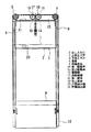
図1及び図2は、この発明の実施の形態の一例を示す図で、図1は正面図、図2は図1の要部を概念的に示す側面図である。図において、1は小荷物専用昇降機のかご、2はかご1に設けられた出し入れ口、3は出し入れ口2の上半を開閉する上側上下戸、4は出し入れ口2の下半を開閉する下側上下戸である。
【0017】
12は出し入れ口2の間口方向の両側の縁部にそれぞれ配置されて長手が上下方向に配置された案内レール、13は桁で、両側の案内レール12の上端部を連結して配置されて出し入れ口2の縁部の上方に配置されている。5は桁13に枢着されて出し入れ口2の縁部の上方に配置され、かつ出し入れ口2の間口方向の両側にそれぞれ配置された滑車である。
【0018】
6は一端が上側上下戸3の間口方向の中心寄りに連結されて滑車5に巻掛けられ他端は下側上下戸4に連結されたロープからなる可撓条体、14は第一駆動車で、桁13に枢着されて出し入れ口2の縁部の上方に配置され、かつ出し入れ口2の間口方向の中心寄りに配置されて一側の可撓条体6が巻掛けられている。15は第二駆動車で、桁13に枢着されて出し入れ口2の縁部の上方に配置され、かつ出し入れ口2の間口方向の中心寄りに配置されて他側の可撓条体6が巻掛けられている。
【0019】
16は桁13に装着されて第一駆動車14を回転駆動する電動機、17は伝動機構で、第一駆動車14に固定された平歯車からなる第一歯車18及び第二駆動車15に固定されて第一歯車18と噛み合う第二歯車19によって構成されている。20は出し入れ口2の上縁部に設けられて上側上下戸3が全閉位置に下降したときに動作するスイッチからなる戸閉検出器、21は桁13に設けられて上側上下戸3が全開位置に上昇したときに動作するスイッチからなる戸開検出器である。
【0020】
上記のように構成された小荷物専用昇降機用出し入れ口装置において、出し入れ口2の戸閉時において上半が上側上下戸3、下半は下側上下戸4によって閉塞される。そして、この状態において下降位置に配置された上側上下戸3によって戸閉検出器20が動作して出し入れ口2の全閉が検出される。
【0021】
また、出し入れ口2の戸開には電動機16が付勢されて第一駆動車14の回転駆動により一側の可撓条体6が引き上げられ、また第一駆動車14が駆動されて回転することによって伝動機構17を介し、すなわち第一歯車18及び第二歯車19の噛み合いによって第二駆動車15が回転駆動される。
【0022】
これにより、他側の可撓条体6が引き上げられて上側上下戸3が案内レール12に案内されて上昇し、また下側上下戸4が案内レール12に案内されて下降して出し入れ口2が開放される。そして、この状態において上昇位置に配置された上側上下戸3によって戸開検出器21が動作して出し入れ口2の全開が検出される。
【0023】
上記のような構成では、前述の図7における上側上下戸3に連結された駆動ロープ9、つり合おもり10を省くことができる。また、出し入れ口2の縁部の上方位置に戸閉検出器20、戸開検出器21が設けられるので、出し入れ口2の幅方向における特別なスペースを準備する必要がなく、出し入れ口装置の間口方向の所要スペースを少なくすることができる。また、設置された戸閉検出器20等を容易に保守点検することができるので、保守点検作業の能率を向上することができる。
【0024】
このため、上側上下戸3等を駆動する装置の構成部材数が少なくなって設置費用を節減できる。また、電動機16、伝動機構17、戸閉検出器20、戸開検出器21が出し入れ口2のほぼ間口内に配置されるので、上側上下戸3、下側上下戸4を駆動する小荷物専用昇降機用出し入れ口装置の設置所要スペースが減少して少ないスペースに出し入れ口装置を容易に設置することができる。
【0025】
また、電動機16、伝動機構17、戸閉検出器20、戸開検出器21が出し入れ口2のほぼ間口内に配置される。このため、昇降路における出し入れ口2の間口の外側に出し入れ口装置の設置スペースを要しない。このため、手動開閉機構からなる既設の小荷物専用昇降機用出し入れ口装置を容易に電動開閉機構の出し入れ口装置に改修することができる。
【0026】
また、図1及び図2の実施の形態において、伝動機構17が次に述べるように構成された場合、すなわち第一歯車18及び第二歯車19の両者間にアイドラ歯車を設けて上記両者がアイドラ歯車を介して動作する構成、また第一駆動車14及び第二駆動車15が後述するたすき掛け伝動条体31による伝動手段により動作する構成であっても、図1及び図2の実施の形態と同様な作用が得られる。
【0027】
実施の形態2.
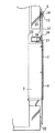
図3及び図4は、この発明の他の実施の形態の一例を示す図で、図3は正面図、図4は図3の要部を概念的に示す側面図である。図において、前述の図1及び図2と同符号は相当部分を示し、22は小荷物専用昇降機の昇降路、2は昇降路22に設けられた出し入れ口、3は出し入れ口2の上半を開閉する上側上下戸、4は出し入れ口2の下半を開閉する下側上下戸である。
【0028】
12は出し入れ口2の間口方向の両側の縁部にそれぞれ配置されて長手が上下方向に配置された案内レール、13は桁で、両側の案内レール12の上端部を連結して配置されて出し入れ口2の縁部の上方に配置されている。5は桁13に枢着されて出し入れ口2の縁部の上方に配置され、かつ出し入れ口2の間口方向の両側にそれぞれ配置された滑車である。
【0029】
6は一端が上側上下戸3の間口方向の中心寄りに連結されて滑車5に巻掛けられ他端は下側上下戸4に連結されたロープからなる可撓条体、14は第一駆動車で、桁13に枢着されて出し入れ口2の縁部の上方に配置され、かつ出し入れ口2の間口方向の中心寄りに配置されて一側の可撓条体6が巻掛けられている。15は第二駆動車で、桁13に枢着されて出し入れ口2の縁部の上方に配置され、かつ出し入れ口2の間口方向の中心寄りに配置されて他側の可撓条体6が巻掛けられている。
【0030】
23は出し入れ口2の上枠の上面側に装着された電動機、24は電動機23の出力軸に固定された出力駆動車、25は第一駆動車14と同軸に配置され第一駆動車14に固定された入力駆動車、26は無端状をなし出力駆動車24及び入力駆動車25に巻掛けられた駆動条体である。27は出力駆動車24、入力駆動車25及び駆動条体26からなる巻掛伝動機構である。
【0031】
上記のように構成された小荷物専用昇降機用出し入れ口装置においても、出し入れ口2の戸閉時において上半が上側上下戸3、下半は下側上下戸4によって閉塞される。そして、この状態において下降位置に配置された上側上下戸3によって戸閉検出器20が動作して出し入れ口2の全閉が検出される。
【0032】
また、出し入れ口2の戸開には電動機23が付勢されて出力駆動車24の回転が巻掛伝動機構27により、すなわち駆動条体26を介して入力駆動車25に伝達される。これにより、第一駆動車14が回転駆動されて一側の可撓条体6が引き上げられ、また、第一駆動車14が駆動されて回転することによって伝動機構17を介し、すなわち第一歯車18及び第二歯車19の噛み合いによって第二駆動車15が回転駆動される。
【0033】
これにより、他側の可撓条体6が引き上げられて上側上下戸3が案内レール12に案内されて上昇し、また下側上下戸4が案内レール12に案内されて下降して出し入れ口2が開放される。そして、この状態において上昇位置に配置された上側上下戸3によって戸開検出器21が動作して出し入れ口2の全開が検出される。
【0034】
このように、図3及び図4に示す構成においても前述の図7における上側上下戸3に連結された駆動ロープ9、つり合おもり10を省くことができる。したがって、詳細な説明を省略するが図3及び図4の実施の形態においても図1及び図2の実施の形態と同様な作用が得られる。
【0035】
また、図3及び図4の実施の形態において、電動機23が、出し入れ口2の上枠と、この上枠の上面側における昇降路22壁下端との間に形成された空所に設けられて、両側の案内レール12の相互間に配置される。このため、小荷物専用昇降機用出し入れ口装置の設置所要スペースが減少して少ないスペースに出し入れ口装置を容易に設置することができる。
【0036】
また、出力駆動車24、入力駆動車25及び駆動条体26からなる巻掛伝動機構27による電動機23からの駆動系を薄形とし、これらの駆動系が出し入れ口2の上枠の上方における昇降路22壁の内側に配置される。このため、出し入れ口2の上枠の上方の昇降路22壁に特殊な切り欠きを設けたり、特別に薄くしたりする等の建築工事における特別な対策が不要である。したがって、小荷物専用昇降機用出し入れ口装置を昇降路22に容易に設置することができる。
【0037】
さらに電動機23を、出し入れ口2の上枠の上面側における昇降路22壁下端との間に水平方向に形成された空所内に配置して、両側の案内レール12の相互間において出し入れ口2の間口方向に移動可能に装着する。このような構成によって、電動機23を出し入れ口2の間口方向に適宜に移動することによって駆動条体26の張力を容易に調整することができ、据付、保守作業の能率を向上することができる。
【0038】
実施の形態3.
図5も、この発明の他の実施の形態の一例を示す図で、出し入れ口装置を概念的に示す斜視図である。なお、図5の他は前述の図1及び図2と同様に小荷物専用昇降機用出し入れ口装置が構成されている。図において、図1及び図2と同符号は相当部分を示し、14は出し入れ口2の間口方向の一方の縁部の上方に配置されて一側の可撓条体6が巻掛けられた第一駆動車、15は出し入れ口2の間口方向の他方の縁部の上方に配置されて他側の可撓条体6が巻掛けられた第二駆動車である。
【0039】
28は伝動機構であり、第一駆動車14と同軸に配置され第一駆動車14に固定された第一伝動車29、第二駆動車15と同軸に配置され第二駆動車15に固定された第二伝動車30並びに無端状をなし第一伝動車29及び第二伝動車30にたすき掛けにより巻掛けられた伝動条体31によって構成されている。
【0040】
上記のように構成された小荷物専用昇降機用出し入れ口装置においても、出し入れ口2の戸閉時において上半が上側上下戸3、下半は下側上下戸4によって閉塞される。そして、この状態において下降位置に配置された上側上下戸3によって戸閉検出器20が動作して出し入れ口2の全閉が検出される。
【0041】
また、出し入れ口2の戸開には電動機16が付勢されて第一駆動車14の回転により第一駆動車14が回転駆動されて一側の可撓条体6が引き上げられ、また、第一駆動車14が駆動されて回転することによって伝動機構28を介し、すなわち伝動条体31、第二伝動車30を介して第二駆動車15が回転し、他側の可撓条体6が引き上げられる。
【0042】
これによって、案内レール12に案内されて上側上下戸3が上昇し、また下側上下戸4が下降して出し入れ口2が開放される。そして、この状態において上昇位置に配置された上側上下戸3によって戸開検出器21が動作して出し入れ口2の全開が検出される。
【0043】
このように、図5に示す構成においても前述の図7における上側上下戸3に連結された駆動ロープ9、つり合おもり10を省くことができる。したがって、詳細な説明を省略するが図5の実施の形態においても図1及び図2の実施の形態と同様な作用が得られる。
【0044】
また、図5の実施の形態において、前述の図3及び図4の実施の形態と同様に出し入れ口2の上枠の上面側における昇降路22壁下端との間の空所内に電動機16を設ける。そして、図3及び図4における駆動条体26によって第一伝動車29及び第二伝動車30のいずれかを駆動する。このような構成によっても図5の実施の形態における作用を得ることができる。
【0045】
実施の形態4.
図6も、この発明の他の実施の形態の一例を示す図で前述の図4相当図である。なお、図6の他は前述の図1及び図2と同様に小荷物専用昇降機用出し入れ口装置が構成されている。図において、図1及び図2と同符号は相当部分を示し、32はユニット形の出し入れ口フレームで、出し入れ口2が設けられた建物の階床に床面から天井側に向かって立設されている。33は電動機室で、出し入れ口フレーム32の天井寄り位置に設けられて昇降路22側が開口して反昇降路22側に突出して形成されている。34は電動機室33内に設置された電動機で、第一駆動車14を駆動する。
【0046】
上記のように構成された小荷物専用昇降機用出し入れ口装置においても、電動機34が付勢されて上側上下戸3及び下側上下戸4が駆動されて出し入れ口2が開閉される。そして、図6に示す構成においても前述の図7における上側上下戸3に連結された駆動ロープ9、つり合おもり10を省くことができる。したがって、詳細な説明を省略するが図6の実施の形態においても図1及び図2の実施の形態と同様な作用が得られる。
【0047】
また、図6の構成において、出し入れ口フレーム32の奥行きが浅くなるので、この奥行き寸法に電動機34を設置することが困難である。しかし、出し入れ口2が設けられた階床の天井寄りに設けられた電動機室33に電動機34が配置される。このため、出し入れ口2が設けられた階床の邪魔にならない位置に電動機34を不都合なく設置することができて、ユニット形による後付け式の小荷物専用昇降機用出し入れ口装置を実現できる。したがって、手動開閉機構からなる既設の小荷物専用昇降機用出し入れ口装置を電動開閉機構の出し入れ口装置に改修する工事に容易に対応することができる。
【0048】
【発明の効果】
この発明は以上説明したように、昇降路壁の開口部に設けられた出し入れ口と、出し入れ口の上半を開閉する上側上下戸と、出し入れ口の下半を開閉する下側上下戸と、出し入れ口の上枠の上方となる昇降路壁に枢着され、出し入れ口における間口方向の両側に配置された第一滑車及び第二滑車と、出し入れ口の上枠の上方となる昇降路壁に枢着され、出し入れ口における間口方向の中心寄りに配置された第一駆動車及び第二駆動車と、第一駆動車に固定された第一歯車及び第二駆動車に固定されて第一歯車と噛み合う第二歯車からなる伝動機構と、一端が上側上下戸に連結されて第一駆動車及び第一滑車に巻掛けられ、他端が下側上下戸に連結された第一可撓条体と、一端が上側上下戸に連結されて第二駆動車及び第二滑車に巻掛けられ、他端が下側上下戸に連結された第二可撓条体と、出し入れ口の上枠の上面側に設けられ、上枠と開口部を形成する昇降路壁下端との間に配置された電動機と、電動機及び第一駆動車に設けられ、電動機の駆動力を第一駆動車に伝達する巻掛伝動機構と、を設けたものである。
【0051】
これによって、出し入れ口の上半が上側上下戸、下半は下側上下戸によって閉塞される。そして、電動機が付勢されて巻掛伝動機構を介して第一駆動車が回転駆動されて第一可撓条体が引き上げられ、また第一駆動車の回転が伝動機構によって第二駆動車に伝動されて第二可撓条体が引き上げられる。これにより、上側上下戸が上昇し、また下側上下戸が下降して出し入れ口が開放される。このような構成により出し入れ口装置の構成部材数が少なくなって設置費用を節減でき、また設置所要スペースが減少して出し入れ口装置の設置を容易化する効果がある。また、手動開閉機構からなる既設の出し入れ口装置の電動開閉機構への改修を容易化する効果がある。
【0052】
また、この発明は以上説明したように、昇降路壁の開口部に設けられた出し入れ口と、出し入れ口の上半を開閉する上側上下戸と、出し入れ口の下半を開閉する下側上下戸と、出し入れ口の上枠の上方となる昇降路壁に枢着され、出し入れ口における間口方向の両側に配置された第一駆動車及び第二駆動車と、第一駆動車に固定された第一伝動車及び第二駆動車に固定された第二伝動車の両者並びにこれら両者に巻掛けられた伝動条体からなる伝動機構と、一端が上側上下戸に連結されて第一駆動車に巻掛けられ、他端が下側上下戸に連結された第一可撓条体と、一端が上側上下戸に連結されて第二駆動車に巻掛けられ、他端が下側上下戸に連結された第二可撓条体と、出し入れ口の上枠の上面側に設けられ、上枠と開口部を形成する昇降路壁下端との間に配置された電動機と、電動機及び第一駆動車に設けられ、電動機の駆動力を第一駆動車に伝達する巻掛伝動機構と、を設けたものである。
【0053】
これによって、出し入れ口の上半が上側上下戸、下半は下側上下戸によって閉塞される。そして、電動機が付勢されて巻掛伝動機構を介して第一駆動車が回転駆動されて第一可撓条体が引き上げられ、また第一駆動車の回転が伝動機構により第二駆動車に伝動されて第二駆動車の回転駆動によって第二可撓条体が引き上げられる。これにより、上側上下戸が上昇し、また下側上下戸が下降して出し入れ口が開放される。このような構成により出し入れ口装置の構成部材数が少なくなって設置費用を節減でき、また設置所要スペースが減少して出し入れ口装置の設置を容易化する効果がある。また、手動開閉機構からなる既設の出し入れ口装置の電動開閉機構への改修を容易化する効果がある。
【0054】
また、この発明は以上説明したように、出し入れ口の上縁部に設けられて上側上下戸が全閉位置に下降したときに動作する戸閉検出器と、出し入れ口の上方に設けられて上側上下戸が全開位置に上昇したときに動作する戸開検出器とを設けたものである。
【0055】
このように、出し入れ口の縁部の上方位置に戸閉検出器、戸開検出器が設けられるので、特別なスペースを要せずに戸閉検出器等を配置でき、設置所要スペースが減少して出し入れ口装置の設置を容易化する効果がある。また、手動開閉機構からなる既設の出し入れ口装置の電動開閉機構への改修を容易化する効果がある。また、設置された戸閉検出器等を出し入れ口の上部において容易に保守点検することができ、保守点検作業の能率を向上する効果がある。
【図面の簡単な説明】
【図1】 この発明の実施の形態1を示す正面図。
【図2】 図1の要部を概念的に示す側面図。
【図3】 この発明の実施の形態2を示す正面図。
【図4】 図3の要部を概念的に示す側面図。
【図5】 この発明の実施の形態3を概念的に示す斜視図。
【図6】 この発明の実施の形態4を概念的に示す図で、前述の図4相当図である。
【図7】 従来の小荷物専用昇降機用出し入れ口装置を概念的に示す斜視図。
【符号の説明】
2 出し入れ口、 3 上側上下戸、 4 下側上下戸、 5 滑車、6 可撓条体、 14 第一駆動車、 15 第二駆動車、 16電動機、 17 伝動機構、 18 第一歯車、 19 第二歯車、
20 戸閉検出器、 21 戸開検出器、 23 電動機、 27 巻掛伝動機構、 28 伝動機構、 29 第一伝動車、 30 第二伝動車、 31 伝動条体。[0001]
BACKGROUND OF THE INVENTION
The present invention relates to a dam waiter, that is, a loading / unloading port for a small baggage elevator installed in a loading / unloading port provided in a cage of a small baggage elevator and a loading / unloading port provided in a hoistway.
[0002]
[Prior art]
FIG. 7 is a diagram showing a conventional loading / unloading device for an elevator for small luggage, and is a perspective view conceptually showing the loading / unloading device. In the figure, 1 is a car for a small luggage elevator, 2 is a loading / unloading port provided in the
[0003]
5 is a pulley pivotally mounted above the edge of the inlet /
[0004]
Reference numeral 8 denotes a driving wheel that is mounted above the edge of the inlet /
[0005]
[0006]
A conventional baggage elevator apparatus is constructed as described above. When the
[0007]
[Problems to be solved by the invention]
In the conventional lifting / unloading device for small baggage as described above, the driving rope 9 driven by the
[0008]
Further, the
[0009]
Further, in the case where the
[0010]
In addition, as a structure of the loading / unloading port apparatus in which the driving rope 9 and the
[0011]
The present invention has been made to solve such problems, and an object of the present invention is to provide a loading / unloading device for a small baggage elevator that has an electric opening / closing function and can be easily installed.
[0012]
[Means for Solving the Problems]
In the small baggage elevator apparatus according to the present invention, Access port provided in the opening of the hoistway wall; The upper door that opens and closes the upper half of the doorway, the lower door that opens and closes the lower half of the doorway, and the doorway Upper frame Above Hoistway wall Pivoted to , Both sides of frontage direction at entrance / exit In Arranged first pulley And second pulley When , Outlet Top border Above Hoistway wall Pivoted to Placed near the center of the frontage direction at the entrance First drive vehicle And second drive car When , A transmission mechanism comprising a first gear fixed to the first drive wheel and a second gear fixed to the second drive wheel and meshed with the first gear; , One end is connected to the upper door First drive vehicle and first Wrapped around a pulley , The other end But Connected to the lower door first A flexible strip; One end is connected to the upper door and the second drive wheel and the second pulley are wound around, the other end is connected to the lower door and the second flexible strip, and the upper side of the upper frame of the access port An electric motor provided between the upper frame and the lower end of the hoistway wall forming the opening, and a winding transmission provided in the electric motor and the first driving vehicle for transmitting the driving force of the electric motor to the first driving vehicle Mechanism, Is provided.
[0014]
Moreover, in the loading / unloading device for the elevator for small luggage according to the present invention, Access port provided in the opening of the hoistway wall; An upper door that opens and closes the upper half of the doorway; a lower door that opens and closes the lower half of the doorway; A first drive vehicle and a second drive vehicle that are pivotally attached to a hoistway wall that is above the upper frame of the entrance / exit, and are arranged on both sides of the entrance / exit in the frontage direction; Both the first transmission vehicle fixed to the first drive vehicle and the second transmission vehicle fixed to the second drive vehicle, and both In A transmission mechanism composed of wound transmission strips; , One end is connected to the upper door First drive vehicle Wrapped around , The other end But Connected to the lower door first A flexible strip; One end is connected to the upper door and is wound around the second drive wheel, and the other end is connected to the lower door and the upper flexible door is provided on the upper surface of the upper frame of the access port. An electric motor disposed between the frame and the lower end of the hoistway wall forming the opening, a winding transmission mechanism provided in the electric motor and the first driving vehicle, and transmitting the driving force of the electric motor to the first driving vehicle; Is provided.
[0015]
Further, in the baggage elevator apparatus according to the present invention, the door closing detector provided at the upper edge of the door and operating when the upper door is lowered to the fully closed position, Upward And a door open detector that operates when the upper upper door is raised to the fully open position.
[0016]
DETAILED DESCRIPTION OF THE INVENTION
Embodiment 1 FIG.
1 and 2 are views showing an example of an embodiment of the present invention. FIG. 1 is a front view, and FIG. 2 is a side view conceptually showing an essential part of FIG. In the figure, 1 is a car for a small luggage elevator, 2 is a loading / unloading port provided in the
[0017]
[0018]
6 is a flexible strip made of a rope having one end connected near the center of the
[0019]
[0020]
In the baggage elevator apparatus configured as described above, the upper half is closed by the upper
[0021]
In addition, an
[0022]
As a result, the
[0023]
In the above configuration, the drive rope 9 and the
[0024]
For this reason, the number of constituent members of the device for driving the upper
[0025]
In addition, the
[0026]
In the embodiment shown in FIGS. 1 and 2, when the
[0027]
3 and 4 are views showing an example of another embodiment of the present invention. FIG. 3 is a front view, and FIG. 4 is a side view conceptually showing the main part of FIG. In the figure, the same reference numerals as those in FIGS. 1 and 2 indicate the corresponding parts, 22 is a hoistway for a small baggage elevator, 2 is a loading / unloading port provided in the hoisting
[0028]
[0029]
6 is a flexible strip made of a rope having one end connected near the center of the
[0030]
23 is an electric motor mounted on the upper surface side of the upper frame of the entrance /
[0031]
Also in the baggage elevating / unloading device configured as described above, the upper half is closed by the upper
[0032]
Further, when the
[0033]
As a result, the
[0034]
3 and FIG. 4, the driving rope 9 and the
[0035]
3 and 4, the
[0036]
Further, the drive system from the
[0037]
Furthermore, the
[0038]
FIG. 5 is also a diagram showing an example of another embodiment of the present invention, and is a perspective view conceptually showing the access port apparatus. Except for FIG. 5, a baggage dedicated elevator access device is configured in the same manner as in FIGS. 1 and 2 described above. In the figure, the same reference numerals as those in FIGS. 1 and 2 indicate the corresponding parts, and 14 is arranged above one edge of the entrance /
[0039]
[0040]
Also in the baggage elevating / unloading device configured as described above, the upper half is closed by the upper
[0041]
In addition, when the
[0042]
As a result, the upper
[0043]
Thus, in the configuration shown in FIG. 5, the drive rope 9 and the
[0044]
Further, in the embodiment of FIG. 5, the
[0045]
FIG. 6 is also a diagram showing an example of another embodiment of the present invention, which corresponds to FIG. 4 described above. Except for FIG. 6, a baggage elevating / unloading port device is configured as in FIGS. 1 and 2 described above. In the figure, the same reference numerals as in FIG. 1 and FIG. 2 indicate the corresponding parts, and 32 is a unit-type entrance / exit frame, which stands on the floor of the building where the entrance /
[0046]
Also in the loading / unloading device for a small baggage elevator configured as described above, the
[0047]
Further, in the configuration of FIG. 6, the depth of the entrance /
[0048]
【The invention's effect】
As described above, the present invention Access port provided in the opening of the hoistway wall; The upper door that opens and closes the upper half of the doorway, the lower door that opens and closes the lower half of the doorway, and the doorway Upper frame Above Hoistway wall Pivoted to , Both sides of frontage direction at entrance / exit In Arranged first pulley And second pulley When , Outlet Top border Above Hoistway wall Pivoted to Placed near the center of the frontage direction at the entrance First drive vehicle And second drive car When , A transmission mechanism comprising a first gear fixed to the first drive wheel and a second gear fixed to the second drive wheel and meshed with the first gear; , One end is connected to the upper door First drive vehicle and first Wrapped around a pulley , The other end But Connected to the lower door first A flexible strip; One end is connected to the upper door and the second drive wheel and the second pulley are wound around, the other end is connected to the lower door and the second flexible strip, and the upper side of the upper frame of the access port An electric motor provided between the upper frame and the lower end of the hoistway wall forming the opening, and a winding transmission provided in the electric motor and the first driving vehicle for transmitting the driving force of the electric motor to the first driving vehicle Mechanism, Is provided.
[0051]
As a result, the upper half of the entrance / exit is closed by the upper upper door and the lower half is closed by the lower upper door. Then, the electric motor is energized and the first drive vehicle is driven to rotate through the winding transmission mechanism. first The flexible strip is pulled up, and the rotation of the first drive vehicle is transmitted to the second drive vehicle by the transmission mechanism. second The flexible strip is pulled up. As a result, the upper upper door is raised and the lower upper door is lowered to open the entrance. With such a configuration, the number of constituent members of the inlet / outlet apparatus can be reduced, and the installation cost can be reduced, and the installation required space can be reduced and the installation of the inlet / outlet apparatus can be facilitated. In addition, there is an effect of facilitating the modification of the existing opening / closing device comprising the manual opening / closing mechanism to the electric opening / closing mechanism.
[0052]
In addition, as described above, the present invention Access port provided in the opening of the hoistway wall; An upper door that opens and closes the upper half of the doorway; a lower door that opens and closes the lower half of the doorway; A first drive vehicle and a second drive vehicle that are pivotally attached to a hoistway wall that is above the upper frame of the entrance / exit, and are arranged on both sides of the entrance / exit in the frontage direction; Both the first transmission vehicle fixed to the first drive vehicle and the second transmission vehicle fixed to the second drive vehicle, and both In A transmission mechanism composed of wound transmission strips; , One end is connected to the upper door First drive vehicle Wrapped around , The other end But Connected to the lower door first A flexible strip; One end is connected to the upper door and is wound around the second drive wheel, and the other end is connected to the lower door and the upper flexible door is provided on the upper surface of the upper frame of the access port. An electric motor disposed between the frame and the lower end of the hoistway wall forming the opening, a winding transmission mechanism provided in the electric motor and the first driving vehicle, and transmitting the driving force of the electric motor to the first driving vehicle; Is provided.
[0053]
As a result, the upper half of the entrance / exit is closed by the upper upper door and the lower half is closed by the lower upper door. And the motor is energized Via the winding transmission mechanism The first drive car is driven to rotate first The flexible strip is pulled up, and the rotation of the first drive vehicle is transmitted to the second drive vehicle by the transmission mechanism, and the second drive vehicle is driven to rotate. second The flexible strip is pulled up. As a result, the upper upper door is raised and the lower upper door is lowered to open the entrance. With such a configuration, the number of constituent members of the inlet / outlet apparatus can be reduced, and the installation cost can be reduced, and the installation required space can be reduced and the installation of the inlet / outlet apparatus can be facilitated. In addition, there is an effect of facilitating the modification of the existing opening / closing device comprising the manual opening / closing mechanism to the electric opening / closing mechanism.
[0054]
In addition, as described above, the present invention provides a door closing detector provided at the upper edge of the inlet / outlet opening and operating when the upper upper and lower doors are lowered to the fully closed position. Upward And a door open detector that operates when the upper upper and lower doors are raised to the fully open position.
[0055]
As described above, since the door closing detector and the door opening detector are provided above the edge of the entrance / exit, the door closing detector and the like can be arranged without requiring a special space, and the required installation space is reduced. This has the effect of facilitating the installation of the inlet / outlet device. In addition, there is an effect of facilitating the modification of the existing opening / closing device comprising the manual opening / closing mechanism to the electric opening / closing mechanism. In addition, the installed door closing detector and the like can be easily inspected and maintained at the upper part of the entrance / exit, thereby improving the efficiency of maintenance and inspection work.
[Brief description of the drawings]
FIG. 1 is a front view showing a first embodiment of the present invention.
FIG. 2 is a side view conceptually showing the main part of FIG.
FIG. 3 is a front
4 is a side view conceptually showing the main part of FIG. 3. FIG.
FIG. 5 is a perspective view conceptually showing
FIG. 6 is a diagram conceptually showing
FIG. 7 is a perspective view conceptually showing a conventional loading / unloading device for an elevator for small luggage.
[Explanation of symbols]
2 entrance / exit, 3 upper upper / lower doors, 4 lower upper / lower doors, 5 pulley, 6 flexible strip, 14 first drive vehicle, 15 second drive vehicle, 16 electric motor, 17 transmission mechanism, 18 first gear, 19 first gear Two gears,
20 door closing detectors, 21 door opening detectors, 23 electric motors, 27 winding transmission mechanisms, 28 transmission mechanisms, 29 first transmission vehicles, 30 second transmission vehicles, 31 transmission strips.
Claims (3)
上記出し入れ口の上半を開閉する上側上下戸と、
上記出し入れ口の下半を開閉する下側上下戸と、
上記出し入れ口の上枠の上方となる上記昇降路壁に枢着され、上記出し入れ口における間口方向の両側に配置された第一滑車及び第二滑車と、
上記出し入れ口の上枠の上方となる上記昇降路壁に枢着され、上記出し入れ口における間口方向の中心寄りに配置された第一駆動車及び第二駆動車と、
上記第一駆動車に固定された第一歯車及び上記第二駆動車に固定されて上記第一歯車と噛み合う第二歯車からなる伝動機構と、
一端が上記上側上下戸に連結されて上記第一駆動車及び上記第一滑車に巻掛けられ、他端が上記下側上下戸に連結された第一可撓条体と、
一端が上記上側上下戸に連結されて上記第二駆動車及び上記第二滑車に巻掛けられ、他端が上記下側上下戸に連結された第二可撓条体と、
上記出し入れ口の上枠の上面側に設けられ、上記上枠と上記開口部を形成する上記昇降路壁下端との間に配置された電動機と、
上記電動機及び上記第一駆動車に設けられ、上記電動機の駆動力を上記第一駆動車に伝達する巻掛伝動機構と、
を備えたことを特徴とする小荷物専用昇降機用出し入れ口装置。 Access port provided in the opening of the hoistway wall;
An upper vertical door for opening and closing the upper half of the loading and unloading opening,
A lower door that opens and closes the lower half of the outlet, and
Pivoted upward to become the hoistway wall of the upper frame of the loading and unloading opening, a first pulley and a second pulley disposed on either side of the frontage direction of the loading and unloading opening,
A first drive vehicle and a second drive vehicle that are pivotally attached to the hoistway wall above the upper frame of the access port, and are arranged closer to the center in the frontage direction at the access port ;
A transmission mechanism comprising a first gear fixed to the first driving wheel and a second gear fixed to the second driving wheel and meshing with the first gear ;
One end connected to the upper vertical door wound around the first drive wheel and the first pulley, a first flexible strip member whose other end is connected to the lower vertical door,
A second flexible strip having one end connected to the upper upper door and wound around the second drive wheel and the second pulley, and the other end connected to the lower upper door;
An electric motor which is provided on the upper surface side of the upper frame of the access port, and is arranged between the upper frame and the lower end of the hoistway wall forming the opening;
A winding transmission mechanism that is provided in the electric motor and the first drive vehicle, and transmits a driving force of the electric motor to the first drive vehicle;
Parcel dedicated elevator for loading and unloading opening device characterized by comprising a.
上記出し入れ口の上半を開閉する上側上下戸と、
上記出し入れ口の下半を開閉する下側上下戸と、
上記出し入れ口の上枠の上方となる上記昇降路壁に枢着され、上記出し入れ口における間口方向の両側に配置された第一駆動車及び第二駆動車と、
上記第一駆動車に固定された第一伝動車及び第二駆動車に固定された第二伝動車の両者並びにこれら両者に巻掛けられた伝動条体からなる伝動機構と、
一端が上記上側上下戸に連結されて上記第一駆動車に巻掛けられ、他端が上記下側上下戸に連結された第一可撓条体と、
一端が上記上側上下戸に連結されて上記第二駆動車に巻掛けられ、他端が上記下側上下戸に連結された第二可撓条体と、
上記出し入れ口の上枠の上面側に設けられ、上記上枠と上記開口部を形成する上記昇降路壁下端との間に配置された電動機と、
上記電動機及び上記第一駆動車に設けられ、上記電動機の駆動力を上記第一駆動車に伝達する巻掛伝動機構と、
を備えたことを特徴とする小荷物専用昇降機用出し入れ口装置。 Access port provided in the opening of the hoistway wall;
An upper vertical door for opening and closing the upper half of the loading and unloading opening,
A lower door that opens and closes the lower half of the outlet, and
A first drive vehicle and a second drive vehicle that are pivotally attached to the hoistway wall above the upper frame of the access port, and disposed on both sides of the front / rear direction at the access port;
A first transmission wheel and the second both the second transmission wheel which is fixed to the drive wheel and transmission mechanism comprising a transmission strip body wound around these both fixed to said first drive wheel,
One end connected to the upper vertical door wound around the first drive wheel, a first flexible strip member whose other end is connected to the lower vertical door,
A second flexible strip having one end connected to the upper door and wound around the second drive wheel, and the other end connected to the lower door;
An electric motor which is provided on the upper surface side of the upper frame of the access port, and is arranged between the upper frame and the lower end of the hoistway wall forming the opening;
A winding transmission mechanism that is provided in the electric motor and the first drive vehicle, and transmits a driving force of the electric motor to the first drive vehicle;
Parcel dedicated elevator for loading and unloading opening device characterized by comprising a.
上記出し入れ口の上方に設けられて上記上側上下戸が全開位置に上昇したときに動作する戸開検出器と
を備えたことを特徴とする請求項1又は請求項2に記載の小荷物専用昇降機用出し入れ口装置。A door-closing detector that is provided at the upper edge of the entrance and exit and operates when the upper upper door is lowered to the fully-closed position;
Provided above the loading and unloading opening the upper vertical door is parcel dedicated elevator according to claim 1 or claim 2, characterized in that a door-opening detectors operating when raised to the fully open position In / out device.
Priority Applications (1)
| Application Number | Priority Date | Filing Date | Title |
|---|---|---|---|
| JP2001392381A JP3935722B2 (en) | 2001-12-25 | 2001-12-25 | Entrance / exit device for elevator for small luggage |
Applications Claiming Priority (1)
| Application Number | Priority Date | Filing Date | Title |
|---|---|---|---|
| JP2001392381A JP3935722B2 (en) | 2001-12-25 | 2001-12-25 | Entrance / exit device for elevator for small luggage |
Publications (2)
| Publication Number | Publication Date |
|---|---|
| JP2003192259A JP2003192259A (en) | 2003-07-09 |
| JP3935722B2 true JP3935722B2 (en) | 2007-06-27 |
Family
ID=27599719
Family Applications (1)
| Application Number | Title | Priority Date | Filing Date |
|---|---|---|---|
| JP2001392381A Expired - Fee Related JP3935722B2 (en) | 2001-12-25 | 2001-12-25 | Entrance / exit device for elevator for small luggage |
Country Status (1)
| Country | Link |
|---|---|
| JP (1) | JP3935722B2 (en) |
Cited By (2)
| Publication number | Priority date | Publication date | Assignee | Title |
|---|---|---|---|---|
| CN103863927A (en) * | 2014-03-21 | 2014-06-18 | 都佛电梯设备(上海)有限公司 | Opening linkage mechanism on elevator three doors |
| CN104340824A (en) * | 2014-10-31 | 2015-02-11 | 四川建设机械(集团)股份有限公司 | Construction lift cage with automatically opened-closed door |
Families Citing this family (2)
| Publication number | Priority date | Publication date | Assignee | Title |
|---|---|---|---|---|
| KR100778251B1 (en) * | 2005-11-02 | 2007-11-22 | (주)공간엘리베이터 | Door apparatus of dumbwaiter |
| CN103121616A (en) * | 2012-12-26 | 2013-05-29 | 江苏通祐电梯有限公司 | Vertically sliding elevator door |
-
2001
- 2001-12-25 JP JP2001392381A patent/JP3935722B2/en not_active Expired - Fee Related
Cited By (3)
| Publication number | Priority date | Publication date | Assignee | Title |
|---|---|---|---|---|
| CN103863927A (en) * | 2014-03-21 | 2014-06-18 | 都佛电梯设备(上海)有限公司 | Opening linkage mechanism on elevator three doors |
| CN104340824A (en) * | 2014-10-31 | 2015-02-11 | 四川建设机械(集团)股份有限公司 | Construction lift cage with automatically opened-closed door |
| CN104340824B (en) * | 2014-10-31 | 2016-08-24 | 四川建设机械(集团)股份有限公司 | Construction elevator cage with automatic opener |
Also Published As
| Publication number | Publication date |
|---|---|
| JP2003192259A (en) | 2003-07-09 |
Similar Documents
| Publication | Publication Date | Title |
|---|---|---|
| JP5940220B2 (en) | Elevator car door lock device | |
| CN110304528B (en) | Elevator car ceiling access system | |
| JP2015037995A (en) | Elevator engagement device | |
| JP3935722B2 (en) | Entrance / exit device for elevator for small luggage | |
| KR100835989B1 (en) | Door automatic open and shut apparatus | |
| JP2009249155A (en) | Door opening and closing device of elevator | |
| CN112499446A (en) | Automatic horizontal door device of lift car of hoistway elevator | |
| JP6367131B2 (en) | Door unit and elevator | |
| US3436863A (en) | Door operating means | |
| US3447637A (en) | Elevator system | |
| EP1627842A1 (en) | Door device of elevator | |
| JPWO2005123563A1 (en) | Elevator door equipment | |
| JP2504275B2 (en) | Elevator door device | |
| JPH11292431A (en) | Opening and closing device for elevator car door | |
| JP6546668B2 (en) | Elevator equipment | |
| JP4946153B2 (en) | Elevator smoke detector inspection device | |
| JP2503741B2 (en) | Door device for elevator | |
| US20060180404A1 (en) | Elevator installation with hoistway door and door-closing device | |
| US2235384A (en) | Elevator door operator | |
| KR102204544B1 (en) | Track vehicle system with ascending and descending type two-stage sliding door | |
| JP4135453B2 (en) | Elevator door equipment | |
| JP2549215B2 (en) | Elevator door opener | |
| JP2023090128A (en) | Smoke shielding device and elevator | |
| CN112499444A (en) | Horizontal door device of lift car of hoistway elevator | |
| KR100340320B1 (en) | Elevator |
Legal Events
| Date | Code | Title | Description |
|---|---|---|---|
| A977 | Report on retrieval |
Free format text: JAPANESE INTERMEDIATE CODE: A971007 Effective date: 20061102 |
|
| A131 | Notification of reasons for refusal |
Free format text: JAPANESE INTERMEDIATE CODE: A131 Effective date: 20061114 |
|
| A521 | Written amendment |
Free format text: JAPANESE INTERMEDIATE CODE: A523 Effective date: 20070105 |
|
| TRDD | Decision of grant or rejection written | ||
| A01 | Written decision to grant a patent or to grant a registration (utility model) |
Free format text: JAPANESE INTERMEDIATE CODE: A01 Effective date: 20070227 |
|
| A61 | First payment of annual fees (during grant procedure) |
Free format text: JAPANESE INTERMEDIATE CODE: A61 Effective date: 20070320 |
|
| R150 | Certificate of patent or registration of utility model |
Free format text: JAPANESE INTERMEDIATE CODE: R150 |
|
| LAPS | Cancellation because of no payment of annual fees |