JP3934658B2 - Position detection system - Google Patents
Position detection system Download PDFInfo
- Publication number
- JP3934658B2 JP3934658B2 JP2005218132A JP2005218132A JP3934658B2 JP 3934658 B2 JP3934658 B2 JP 3934658B2 JP 2005218132 A JP2005218132 A JP 2005218132A JP 2005218132 A JP2005218132 A JP 2005218132A JP 3934658 B2 JP3934658 B2 JP 3934658B2
- Authority
- JP
- Japan
- Prior art keywords
- infrared
- screen
- reflected light
- game
- imaging
- Prior art date
- Legal status (The legal status is an assumption and is not a legal conclusion. Google has not performed a legal analysis and makes no representation as to the accuracy of the status listed.)
- Active
Links
- 238000001514 detection method Methods 0.000 title claims description 56
- 238000003384 imaging method Methods 0.000 claims description 37
- 230000003287 optical effect Effects 0.000 claims description 5
- 238000001914 filtration Methods 0.000 claims description 2
- 230000002093 peripheral effect Effects 0.000 claims description 2
- 239000000872 buffer Substances 0.000 description 19
- 238000010191 image analysis Methods 0.000 description 19
- 238000012545 processing Methods 0.000 description 18
- 238000000034 method Methods 0.000 description 17
- 241000283973 Oryctolagus cuniculus Species 0.000 description 8
- 238000010586 diagram Methods 0.000 description 6
- 238000004891 communication Methods 0.000 description 4
- 238000006243 chemical reaction Methods 0.000 description 3
- 230000001678 irradiating effect Effects 0.000 description 3
- 230000000903 blocking effect Effects 0.000 description 2
- 238000012937 correction Methods 0.000 description 2
- 230000000386 athletic effect Effects 0.000 description 1
- 230000007423 decrease Effects 0.000 description 1
- 230000000694 effects Effects 0.000 description 1
- 238000003780 insertion Methods 0.000 description 1
- 230000037431 insertion Effects 0.000 description 1
- 238000009434 installation Methods 0.000 description 1
- 239000003973 paint Substances 0.000 description 1
- 239000004065 semiconductor Substances 0.000 description 1
- 230000001360 synchronised effect Effects 0.000 description 1
- 238000012546 transfer Methods 0.000 description 1
Images


Classifications
-
- A—HUMAN NECESSITIES
- A63—SPORTS; GAMES; AMUSEMENTS
- A63F—CARD, BOARD, OR ROULETTE GAMES; INDOOR GAMES USING SMALL MOVING PLAYING BODIES; VIDEO GAMES; GAMES NOT OTHERWISE PROVIDED FOR
- A63F13/00—Video games, i.e. games using an electronically generated display having two or more dimensions
- A63F13/20—Input arrangements for video game devices
- A63F13/21—Input arrangements for video game devices characterised by their sensors, purposes or types
- A63F13/213—Input arrangements for video game devices characterised by their sensors, purposes or types comprising photodetecting means, e.g. cameras, photodiodes or infrared cells
-
- A—HUMAN NECESSITIES
- A63—SPORTS; GAMES; AMUSEMENTS
- A63F—CARD, BOARD, OR ROULETTE GAMES; INDOOR GAMES USING SMALL MOVING PLAYING BODIES; VIDEO GAMES; GAMES NOT OTHERWISE PROVIDED FOR
- A63F13/00—Video games, i.e. games using an electronically generated display having two or more dimensions
- A63F13/20—Input arrangements for video game devices
- A63F13/21—Input arrangements for video game devices characterised by their sensors, purposes or types
-
- A—HUMAN NECESSITIES
- A63—SPORTS; GAMES; AMUSEMENTS
- A63B—APPARATUS FOR PHYSICAL TRAINING, GYMNASTICS, SWIMMING, CLIMBING, OR FENCING; BALL GAMES; TRAINING EQUIPMENT
- A63B24/00—Electric or electronic controls for exercising apparatus of preceding groups; Controlling or monitoring of exercises, sportive games, training or athletic performances
- A63B24/0003—Analysing the course of a movement or motion sequences during an exercise or trainings sequence, e.g. swing for golf or tennis
-
- A—HUMAN NECESSITIES
- A63—SPORTS; GAMES; AMUSEMENTS
- A63B—APPARATUS FOR PHYSICAL TRAINING, GYMNASTICS, SWIMMING, CLIMBING, OR FENCING; BALL GAMES; TRAINING EQUIPMENT
- A63B63/00—Targets or goals for ball games
-
- A63F13/04—
-
- A—HUMAN NECESSITIES
- A63—SPORTS; GAMES; AMUSEMENTS
- A63F—CARD, BOARD, OR ROULETTE GAMES; INDOOR GAMES USING SMALL MOVING PLAYING BODIES; VIDEO GAMES; GAMES NOT OTHERWISE PROVIDED FOR
- A63F13/00—Video games, i.e. games using an electronically generated display having two or more dimensions
- A63F13/20—Input arrangements for video game devices
- A63F13/21—Input arrangements for video game devices characterised by their sensors, purposes or types
- A63F13/216—Input arrangements for video game devices characterised by their sensors, purposes or types using geographical information, e.g. location of the game device or player using GPS
-
- A—HUMAN NECESSITIES
- A63—SPORTS; GAMES; AMUSEMENTS
- A63F—CARD, BOARD, OR ROULETTE GAMES; INDOOR GAMES USING SMALL MOVING PLAYING BODIES; VIDEO GAMES; GAMES NOT OTHERWISE PROVIDED FOR
- A63F9/00—Games not otherwise provided for
- A63F9/02—Shooting or hurling games
-
- F—MECHANICAL ENGINEERING; LIGHTING; HEATING; WEAPONS; BLASTING
- F41—WEAPONS
- F41J—TARGETS; TARGET RANGES; BULLET CATCHERS
- F41J5/00—Target indicating systems; Target-hit or score detecting systems
- F41J5/08—Infra-red hit-indicating systems
-
- G—PHYSICS
- G06—COMPUTING; CALCULATING OR COUNTING
- G06F—ELECTRIC DIGITAL DATA PROCESSING
- G06F3/00—Input arrangements for transferring data to be processed into a form capable of being handled by the computer; Output arrangements for transferring data from processing unit to output unit, e.g. interface arrangements
- G06F3/01—Input arrangements or combined input and output arrangements for interaction between user and computer
- G06F3/03—Arrangements for converting the position or the displacement of a member into a coded form
- G06F3/0304—Detection arrangements using opto-electronic means
- G06F3/0308—Detection arrangements using opto-electronic means comprising a plurality of distinctive and separately oriented light emitters or reflectors associated to the pointing device, e.g. remote cursor controller with distinct and separately oriented LEDs at the tip whose radiations are captured by a photo-detector associated to the screen
-
- G—PHYSICS
- G06—COMPUTING; CALCULATING OR COUNTING
- G06F—ELECTRIC DIGITAL DATA PROCESSING
- G06F3/00—Input arrangements for transferring data to be processed into a form capable of being handled by the computer; Output arrangements for transferring data from processing unit to output unit, e.g. interface arrangements
- G06F3/01—Input arrangements or combined input and output arrangements for interaction between user and computer
- G06F3/03—Arrangements for converting the position or the displacement of a member into a coded form
- G06F3/041—Digitisers, e.g. for touch screens or touch pads, characterised by the transducing means
- G06F3/042—Digitisers, e.g. for touch screens or touch pads, characterised by the transducing means by opto-electronic means
- G06F3/0421—Digitisers, e.g. for touch screens or touch pads, characterised by the transducing means by opto-electronic means by interrupting or reflecting a light beam, e.g. optical touch-screen
-
- G—PHYSICS
- G06—COMPUTING; CALCULATING OR COUNTING
- G06F—ELECTRIC DIGITAL DATA PROCESSING
- G06F3/00—Input arrangements for transferring data to be processed into a form capable of being handled by the computer; Output arrangements for transferring data from processing unit to output unit, e.g. interface arrangements
- G06F3/01—Input arrangements or combined input and output arrangements for interaction between user and computer
- G06F3/03—Arrangements for converting the position or the displacement of a member into a coded form
- G06F3/041—Digitisers, e.g. for touch screens or touch pads, characterised by the transducing means
- G06F3/042—Digitisers, e.g. for touch screens or touch pads, characterised by the transducing means by opto-electronic means
- G06F3/0425—Digitisers, e.g. for touch screens or touch pads, characterised by the transducing means by opto-electronic means using a single imaging device like a video camera for tracking the absolute position of a single or a plurality of objects with respect to an imaged reference surface, e.g. video camera imaging a display or a projection screen, a table or a wall surface, on which a computer generated image is displayed or projected
-
- A—HUMAN NECESSITIES
- A63—SPORTS; GAMES; AMUSEMENTS
- A63B—APPARATUS FOR PHYSICAL TRAINING, GYMNASTICS, SWIMMING, CLIMBING, OR FENCING; BALL GAMES; TRAINING EQUIPMENT
- A63B24/00—Electric or electronic controls for exercising apparatus of preceding groups; Controlling or monitoring of exercises, sportive games, training or athletic performances
- A63B24/0021—Tracking a path or terminating locations
- A63B2024/0037—Tracking a path or terminating locations on a target surface or at impact on the ground
- A63B2024/0043—Systems for locating the point of impact on a specific surface
-
- A—HUMAN NECESSITIES
- A63—SPORTS; GAMES; AMUSEMENTS
- A63B—APPARATUS FOR PHYSICAL TRAINING, GYMNASTICS, SWIMMING, CLIMBING, OR FENCING; BALL GAMES; TRAINING EQUIPMENT
- A63B2220/00—Measuring of physical parameters relating to sporting activity
- A63B2220/05—Image processing for measuring physical parameters
-
- A—HUMAN NECESSITIES
- A63—SPORTS; GAMES; AMUSEMENTS
- A63B—APPARATUS FOR PHYSICAL TRAINING, GYMNASTICS, SWIMMING, CLIMBING, OR FENCING; BALL GAMES; TRAINING EQUIPMENT
- A63B2220/00—Measuring of physical parameters relating to sporting activity
- A63B2220/80—Special sensors, transducers or devices therefor
- A63B2220/806—Video cameras
-
- A—HUMAN NECESSITIES
- A63—SPORTS; GAMES; AMUSEMENTS
- A63F—CARD, BOARD, OR ROULETTE GAMES; INDOOR GAMES USING SMALL MOVING PLAYING BODIES; VIDEO GAMES; GAMES NOT OTHERWISE PROVIDED FOR
- A63F13/00—Video games, i.e. games using an electronically generated display having two or more dimensions
- A63F13/50—Controlling the output signals based on the game progress
- A63F13/52—Controlling the output signals based on the game progress involving aspects of the displayed game scene
-
- A—HUMAN NECESSITIES
- A63—SPORTS; GAMES; AMUSEMENTS
- A63F—CARD, BOARD, OR ROULETTE GAMES; INDOOR GAMES USING SMALL MOVING PLAYING BODIES; VIDEO GAMES; GAMES NOT OTHERWISE PROVIDED FOR
- A63F2300/00—Features of games using an electronically generated display having two or more dimensions, e.g. on a television screen, showing representations related to the game
- A63F2300/10—Features of games using an electronically generated display having two or more dimensions, e.g. on a television screen, showing representations related to the game characterized by input arrangements for converting player-generated signals into game device control signals
- A63F2300/1043—Features of games using an electronically generated display having two or more dimensions, e.g. on a television screen, showing representations related to the game characterized by input arrangements for converting player-generated signals into game device control signals being characterized by constructional details
-
- A—HUMAN NECESSITIES
- A63—SPORTS; GAMES; AMUSEMENTS
- A63F—CARD, BOARD, OR ROULETTE GAMES; INDOOR GAMES USING SMALL MOVING PLAYING BODIES; VIDEO GAMES; GAMES NOT OTHERWISE PROVIDED FOR
- A63F2300/00—Features of games using an electronically generated display having two or more dimensions, e.g. on a television screen, showing representations related to the game
- A63F2300/10—Features of games using an electronically generated display having two or more dimensions, e.g. on a television screen, showing representations related to the game characterized by input arrangements for converting player-generated signals into game device control signals
- A63F2300/1068—Features of games using an electronically generated display having two or more dimensions, e.g. on a television screen, showing representations related to the game characterized by input arrangements for converting player-generated signals into game device control signals being specially adapted to detect the point of contact of the player on a surface, e.g. floor mat, touch pad
-
- A—HUMAN NECESSITIES
- A63—SPORTS; GAMES; AMUSEMENTS
- A63F—CARD, BOARD, OR ROULETTE GAMES; INDOOR GAMES USING SMALL MOVING PLAYING BODIES; VIDEO GAMES; GAMES NOT OTHERWISE PROVIDED FOR
- A63F2300/00—Features of games using an electronically generated display having two or more dimensions, e.g. on a television screen, showing representations related to the game
- A63F2300/10—Features of games using an electronically generated display having two or more dimensions, e.g. on a television screen, showing representations related to the game characterized by input arrangements for converting player-generated signals into game device control signals
- A63F2300/1087—Features of games using an electronically generated display having two or more dimensions, e.g. on a television screen, showing representations related to the game characterized by input arrangements for converting player-generated signals into game device control signals comprising photodetecting means, e.g. a camera
-
- A—HUMAN NECESSITIES
- A63—SPORTS; GAMES; AMUSEMENTS
- A63F—CARD, BOARD, OR ROULETTE GAMES; INDOOR GAMES USING SMALL MOVING PLAYING BODIES; VIDEO GAMES; GAMES NOT OTHERWISE PROVIDED FOR
- A63F2300/00—Features of games using an electronically generated display having two or more dimensions, e.g. on a television screen, showing representations related to the game
- A63F2300/80—Features of games using an electronically generated display having two or more dimensions, e.g. on a television screen, showing representations related to the game specially adapted for executing a specific type of game
- A63F2300/8023—Features of games using an electronically generated display having two or more dimensions, e.g. on a television screen, showing representations related to the game specially adapted for executing a specific type of game the game being played by multiple players at a common site, e.g. in an arena, theatre, shopping mall using a large public display
-
- A—HUMAN NECESSITIES
- A63—SPORTS; GAMES; AMUSEMENTS
- A63F—CARD, BOARD, OR ROULETTE GAMES; INDOOR GAMES USING SMALL MOVING PLAYING BODIES; VIDEO GAMES; GAMES NOT OTHERWISE PROVIDED FOR
- A63F2300/00—Features of games using an electronically generated display having two or more dimensions, e.g. on a television screen, showing representations related to the game
- A63F2300/80—Features of games using an electronically generated display having two or more dimensions, e.g. on a television screen, showing representations related to the game specially adapted for executing a specific type of game
- A63F2300/8029—Fighting without shooting
-
- A—HUMAN NECESSITIES
- A63—SPORTS; GAMES; AMUSEMENTS
- A63F—CARD, BOARD, OR ROULETTE GAMES; INDOOR GAMES USING SMALL MOVING PLAYING BODIES; VIDEO GAMES; GAMES NOT OTHERWISE PROVIDED FOR
- A63F9/00—Games not otherwise provided for
- A63F9/02—Shooting or hurling games
- A63F9/0291—Shooting or hurling games with a simulated projectile, e.g. an image on a screen
Description
本発明は、物体の位置を検出するシステムに関する。さらに詳しくは、空間内の任意の平面上での物体の位置を検出するシステムに関する。 The present invention relates to a system for detecting the position of an object. More particularly, the present invention relates to a system for detecting the position of an object on an arbitrary plane in space.
ゲームの一種に、実空間内でプレイヤが操作する実オブジェクトと、ゲーム空間内の仮想オブジェクトと、の当たり判定を行うゲームがある。この種のゲームの一つとして、ディスプレイに表示される仮想オブジェクトにプレイヤがボールを当てるゲームがある。
図10は、このゲームにおけるボールの位置検出のための構成を示す説明図である。同図(a)は、ディスプレイDの外周に沿って赤外線照射手段Lx、Lyを配置し、碁盤目上の赤外線網を構成することを示す。各赤外線照射手段Lx,Lyに対向する位置には、赤外線センサSx,Syが、ディスプレイDの外周に沿って配置される。同図(b)は、赤外線照射手段Lx,Ly及び赤外線センサSx,Syは、ディスプレイDのごく近傍に配置されることを示す。プレイヤがディスプレイDに向かって投げたボールがディスプレイDの手前で赤外線を遮断すると、赤外線が遮断されたことを赤外線センサSx,Syが検出する。どの赤外線センサSx,Syが遮断を検出したかを判別することにより、ボールが当たった位置を(x,y)座標で特定する。
One type of game is a game in which a hit determination is made between a real object operated by a player in the real space and a virtual object in the game space. As one of such games, there is a game in which a player hits a ball against a virtual object displayed on a display.
FIG. 10 is an explanatory diagram showing a configuration for detecting the position of the ball in this game. FIG. 4A shows that infrared irradiation means Lx and Ly are arranged along the outer periphery of the display D to constitute an infrared network on a grid. Infrared sensors Sx, Sy are arranged along the outer periphery of the display D at positions facing the respective infrared irradiation means Lx, Ly. FIG. 5B shows that the infrared irradiation means Lx and Ly and the infrared sensors Sx and Sy are arranged in the very vicinity of the display D. When the ball thrown toward the display D by the player blocks the infrared rays before the display D, the infrared sensors Sx and Sy detect that the infrared rays are blocked. By determining which infrared sensor Sx, Sy has detected the interruption, the position hit by the ball is specified by (x, y) coordinates.
しかし、図10に示す方法では、図中x方向及びy方向に沿って配置された赤外線照射手段Lx,Ly及び赤外線センサSx,Syの間隔に、検出精度が依存する。そのため、検出精度を上げようとすると、配置すべき赤外線照射手段Lx,Ly及び赤外線センサSx,Syの数が多くなってしまう。しかも、赤外線照射手段Lx,Lyと赤外線センサSx,Syとが正確に対向するように設置する必要があるので、数が増えるほど設置が困難になる。 However, in the method shown in FIG. 10, the detection accuracy depends on the interval between the infrared irradiation means Lx, Ly and the infrared sensors Sx, Sy arranged along the x direction and the y direction in the figure. Therefore, if it is going to raise detection accuracy, the number of infrared irradiation means Lx and Ly and infrared sensors Sx and Sy which should be arranged will increase. Moreover, since it is necessary to install the infrared irradiation means Lx, Ly and the infrared sensors Sx, Sy so as to face each other accurately, the installation becomes more difficult as the number increases.
また、検出精度を上げようとして赤外線の間隔を狭め、ボールの直径よりも赤外線の間隔の方が小さくなると、1つのボールがx方向及び/またはy方向において、複数の赤外線センサに検出され得る。この場合、1つのボールが複数のボールと誤認識されてしまう可能性がある。
さらに、一度に複数のボールが赤外線網を通過した場合、図10に示す方法では、それぞれの通過位置を検出することが難しい。例えば、2つのボールが、位置P1(x1,y1)、P2(x2,y2)を通過したとする。x1及びx2に対応する位置の赤外線センサは、赤外線の遮断を検知する。同様に、y1及びy2に対応する位置の赤外線センサは、赤外線の遮断を検知する。しかし、これだけでは、x1,x2とy1,y2との組み合わせを特定することができない。すなわち、2つのボールが、位置P1(x1,y1)、P2(x2,y2)を通過したのか、それともP3(x1,y2)、P4(x2,y1)を通過したのかを、判別することができない。
Further, when the interval between infrared rays is narrowed to increase the detection accuracy and the interval between infrared rays becomes smaller than the diameter of the ball, one ball can be detected by a plurality of infrared sensors in the x direction and / or the y direction. In this case, one ball may be erroneously recognized as a plurality of balls.
Furthermore, when a plurality of balls pass through the infrared network at one time, it is difficult to detect the respective passing positions with the method shown in FIG. For example, it is assumed that two balls have passed positions P1 (x1, y1) and P2 (x2, y2). Infrared sensors at positions corresponding to x1 and x2 detect blocking of infrared rays. Similarly, the infrared sensor at a position corresponding to y1 and y2 detects blocking of infrared rays. However, this alone cannot identify the combination of x1, x2 and y1, y2. That is, it is possible to determine whether two balls have passed positions P1 (x1, y1) and P2 (x2, y2) or P3 (x1, y2) and P4 (x2, y1). Can not.
本発明は、空間内の任意の平面における物体の位置を、また物体の数にかかわらず、正確に検出することを目的とする。 An object of the present invention is to accurately detect the position of an object on an arbitrary plane in space and regardless of the number of objects.
前記課題を解決するために、発明1は、下記の手段を有する位置検出システムを提供する。
・平面状の赤外線スクリーンを生成する赤外線スクリーン生成手段、
・任意の複数の被検出物が前記赤外線スクリーンを通過することによる前記赤外線スクリーン上での赤外線の反射を選択的に検出する反射光検出手段、
・前記反射光検出手段が検出した赤外線の複数の反射位置を、前記赤外線スクリーン上で特定する位置特定手段、
・前記赤外線スクリーンを挟んで前記反射光検出手段と反対側に、前記赤外線スクリーンに沿ってその近傍に設けられている実スクリーン。
In order to solve the above-described problems, the
-Infrared screen generating means for generating a planar infrared screen,
Reflected light detection means for selectively detecting reflection of infrared rays on the infrared screen caused by any plurality of detected objects passing through the infrared screen;
· Said plurality of reflection positions of infrared reflected light detecting unit detects the position specifying means for specifying on the infrared screen,
An actual screen provided in the vicinity of the infrared screen on the opposite side of the reflected light detection means along the infrared screen .
ここで、前記反射光検出手段は、
・少なくとも前記実スクリーン全体が画角内に入るように設定され、所定時間間隔で撮像を繰り返す第1撮像手段と、
・前記第1撮像手段に取り付けられ、前記第1撮像手段に入力される光を選択する赤外線フィルタと、を含む。また、前記位置特定手段は、前記第1撮像手段が撮像した各画像を解析することにより、前記赤外線スクリーン上での前記被検出物による赤外線の反射位置を特定する。
Here, the reflected light detecting means is
First imaging means that is set so that at least the entire real screen falls within the angle of view, and repeats imaging at predetermined time intervals;
An infrared filter that is attached to the first imaging unit and that selects light input to the first imaging unit. Further, the position specifying unit specifies an infrared reflection position by the detected object on the infrared screen by analyzing each image picked up by the first image pickup unit.
この位置検出システムでは、赤外線スクリーン上の反射光だけを選択的に検出することにより、反射光の位置を特定する。複数の被検出物が同時に赤外線スクリーンを通過した場合であっても、それぞれの被検出物が赤外線スクリーンを通過した位置を、高精度のセンサを設けることなく、正確に特定することができる。
赤外線スクリーンと実スクリーンとを間近に設置することにより、実スクリーンのどこに被検出物が当たったのかを、実質的に特定することができる。実スクリーンは、赤外線スクリーンを挟んで反射光検出手段と反対側に設置される。なお、赤外線スクリーンが実スクリーンを覆う大きさであれば、実スクリーンの全範囲における位置検出が可能である。
In this position detection system, the position of the reflected light is specified by selectively detecting only the reflected light on the infrared screen. Even when a plurality of objects to be detected have passed through the infrared screen at the same time, the position where each object to be detected has passed through the infrared screen can be accurately identified without providing a high-precision sensor.
By installing the infrared screen and the actual screen close to each other, it is possible to substantially specify where the object to be detected hits on the actual screen. The actual screen is installed on the side opposite to the reflected light detecting means with the infrared screen interposed therebetween. If the infrared screen is large enough to cover the real screen, position detection in the entire range of the real screen is possible.
カメラなどの第1撮像手段で撮像した画像を解析することにより、赤外線スクリーン上での発光位置を、所定時間間隔毎に検出することができる。第1撮像手段としては、CCDカメラやビデオカメラなどを用いることができる。なお、撮像した画像の歪みを補正する手段があることが好ましい。例えば、歪み補正レンズを用いてもよいし、ソフト的に画像の歪みを補正することも可能である。また、第1撮像手段は、1つとは限らない。例えば実スクリーンが大きい場合、実スクリーン全体が複数の第1撮像手段それぞれの画角の総和に収まるように、複数の第1撮像手段を設けても良い。 By analyzing the image captured by the first imaging means such as a camera, the light emission position on the infrared screen can be detected at predetermined time intervals. As the first imaging means, a CCD camera, a video camera, or the like can be used. In addition, it is preferable that there is a means for correcting distortion of the captured image. For example, a distortion correction lens may be used, or image distortion can be corrected in software. Further, the number of first imaging means is not limited to one. For example, when the actual screen is large, a plurality of first imaging units may be provided so that the entire real screen falls within the total angle of view of each of the plurality of first imaging units.
発明2は、前記発明1において、前記赤外線スクリーンと前記実スクリーンとの距離は、前記被検出物の最大長を超えないように調整されている位置検出システムを提供する。
赤外線スクリーンと実スクリーンとの距離は、前記被検出物の最大長を超えないことが好ましい。例えば被検出物がボールである場合を考える。両スクリーンの距離がボールの直径を超えないように調整すると、実スクリーンに当たって跳ね返ったボールによる赤外線の再反射を防止できる。
A second aspect of the present invention provides the position detection system according to the first aspect , wherein a distance between the infrared screen and the actual screen is adjusted so as not to exceed a maximum length of the detected object.
It is preferable that the distance between the infrared screen and the actual screen does not exceed the maximum length of the object to be detected. For example, consider the case where the object to be detected is a ball. By adjusting the distance between the two screens so as not to exceed the diameter of the ball, it is possible to prevent re-reflection of infrared rays by the ball bounced off the actual screen.
発明3は、前記発明1または2において、前記赤外線スクリーン生成手段は、空間内の任意の矩形状平面の周縁の少なくとも一部に配置され、光軸が前記平面上にある赤外線を照射する複数の赤外線照射手段を含んでいる位置検出システムを提供する。
各赤外線照射手段は、矩形状平面上に光軸を有する赤外線を照射する。言い換えれば、赤外線の照射方向は、矩形状平面に含まれる。このように、指向性を持つ赤外線を照射することにより、平面状の赤外線網、すなわち赤外線スクリーンを形成することができる。また、指向性を持つ赤外線を照射することにより、赤外線スクリーンの厚みを押さえることができる。赤外線スクリーンの厚さが小さいほど、赤外線スクリーンと実スクリーンとの距離を縮め、実スクリーンに近いところでの位置検出が可能となる。また、反射光の発光時間を短くすることができるため、複数の被検出物が同時に赤外線スクリーンを通過する場合でも、各被検出物が実スクリーンに当たる位置と当たるタイミングとのずれを小さくすることができる。
A third aspect of the present invention is the first or second aspect , wherein the infrared screen generating means is disposed at least at a part of a peripheral edge of an arbitrary rectangular plane in the space, and emits infrared rays having an optical axis on the plane. A position detection system including infrared irradiation means is provided.
Each infrared irradiation means irradiates infrared rays having an optical axis on a rectangular plane. In other words, the irradiation direction of infrared rays is included in a rectangular plane. Thus, a planar infrared network, that is, an infrared screen can be formed by irradiating infrared rays having directivity. Moreover, the thickness of an infrared screen can be suppressed by irradiating infrared rays having directivity. The smaller the thickness of the infrared screen, the shorter the distance between the infrared screen and the actual screen, and the position detection near the actual screen becomes possible. In addition, since the emission time of the reflected light can be shortened, even when a plurality of detected objects pass through the infrared screen at the same time, it is possible to reduce the deviation between the position where each detected object hits the actual screen and the timing of hitting. it can.
発明4は、前記発明3において、前記複数の赤外線照射手段は、前記矩形状平面を形成する4辺のうち、少なくとも2辺に沿って配置されている位置検出システムを提供する。
対向する2辺に沿ってでもよいし、交差する2辺に沿って赤外線照射手段を配列してもよい。この構成により、矩形状の赤外線スクリーンを形成することができる。この赤外線スクリーンを通過する被検出物には、少なくとも2方向から赤外線が照射される。そのため、複数の被検出物がスクリーンを同時に通過する場合であっても、ある被検出物が他の被検出物の陰になりにくく、複数の被検出物全てにまんべんなく均等に赤外線を照射できる利点がある。
A fourth aspect of the present invention provides the position detection system according to the third aspect , wherein the plurality of infrared irradiation units are arranged along at least two of the four sides forming the rectangular plane.
The infrared irradiation means may be arranged along two opposing sides or along two intersecting sides. With this configuration, a rectangular infrared screen can be formed. The object to be detected that passes through the infrared screen is irradiated with infrared rays from at least two directions. Therefore, even when multiple detection objects pass through the screen at the same time, certain detection objects are less likely to be shaded by other detection objects, and all of the multiple detection objects can be uniformly irradiated with infrared rays. There is.
発明5は、前記発明1〜4において、任意のゲームを実行するゲーム実行手段をさらに有する位置検出システムを提供する。このシステムにおいて、前記実スクリーンは、前記ゲーム実行手段と接続され、前記コンピュータ端末からの画像を出力するディスプレイである。
発明1の位置検出システムをゲームに適用してもよい。コンピュータ端末は、例えば、ディスプレイに表示するゲーム空間中の仮想オブジェクトと、ディスプレイに向かってプレイヤが投げるボールと、の当たり判定を行う。この当たり判定に必要な、ボールとディスプレイとの接触位置の判定に、発明1の位置検出システムを用いるとよい。しかも、複数のボールが同時にディスプレイに当たった場合でも、それぞれのボールと仮想オブジェクトとの当たり判定を個別に行うことができる。そのため、ゲームでの当たり判定の的確さが向上し、ゲームの面白みが一段と増すことを期待できる。
A fifth aspect of the present invention provides the position detection system according to any of the first to fourth aspects, further comprising game execution means for executing an arbitrary game. In this system, the real screen is a display that is connected to the game execution means and outputs an image from the computer terminal.
The position detection system according to the first aspect may be applied to a game. For example, the computer terminal performs a hit determination between a virtual object in the game space displayed on the display and a ball thrown by the player toward the display. The position detection system according to the first aspect of the present invention may be used to determine the contact position between the ball and the display necessary for the hit determination. In addition, even when a plurality of balls hit the display at the same time, it is possible to individually determine whether each ball hits the virtual object. Therefore, the accuracy of the hit determination in the game is improved, and it can be expected that the fun of the game will be further increased.
発明6は、前記発明1〜5において、以下の手段をさらに有する位置検出システムを提供する。
・少なくとも前記実スクリーン全体が画角内に入るように設定され、所定時間間隔でカラー画像の撮像を繰り返す第2撮像手段
・前記第1撮像手段及び前記第2撮像手段が撮像した各画像を解析することにより、前記被検出物の色を判別する色彩特定手段。
A sixth aspect of the present invention provides the position detection system according to the first to fifth aspects, further comprising the following means.
Second imaging means that is set so that at least the entire real screen falls within the angle of view, and repeats imaging of color images at predetermined time intervals. Each image captured by the first imaging means and the second imaging means is analyzed. Color specifying means for determining the color of the object to be detected.
第2撮像手段に可視光を入力してカラー画像を撮像し、第1撮像手段の画像に基づいて特定した位置の色彩を解析すれば、被検出物の色を得ることができる。例えば、複数プレイヤによるゲームにおいてプレイヤ毎に被検出物の色が違う場合、プレイヤ毎に当たり判定を行うことが可能になる。また、第2撮像手段は、1つとは限らない。例えば実スクリーンが大きい場合、実スクリーン全体が複数の第2撮像手段それぞれの画角の総和に収まるように、複数の第2撮像手段を設けても良い。 The color of the object to be detected can be obtained by inputting visible light to the second image pickup means to pick up a color image and analyzing the color at the position specified based on the image of the first image pickup means. For example, if the color of the detected object is different for each player in a game with a plurality of players, it is possible to make a hit determination for each player. Further, the number of the second imaging means is not limited to one. For example, when the actual screen is large, a plurality of second imaging units may be provided so that the entire real screen falls within the total angle of view of each of the plurality of second imaging units.
発明7は、前記発明1〜6において、前記反射光検出手段により検出された反射光が生じたタイミングを検出するタイミング検出手段をさらに有する位置検出システムを提供する。
例えば、被検出物がどのような順序で赤外線スクリーンを通過したのかを特定し、ゲームに生かすことができる。
A seventh aspect of the present invention provides the position detection system according to any of the first to sixth aspects, further comprising timing detection means for detecting timing at which the reflected light detected by the reflected light detection means is generated.
For example, it is possible to specify in what order the detected object has passed through the infrared screen and use it in the game.
発明8は、以下のステップを有する位置検出方法を提供する。
・平面状の赤外線スクリーンを生成する赤外線スクリーン生成ステップ、
・任意の複数の被検出物が前記赤外線スクリーンを通過することによる前記赤外線スクリーン上での赤外線の反射を、反射光検出手段により選択的に検出する反射光検出ステップ、
・前記反射光検出ステップで検出された赤外線の複数の反射位置を、前記赤外線スクリーン上で特定する位置特定ステップ。
The invention 8 provides a position detection method having the following steps.
An infrared screen generation step for generating a planar infrared screen;
A reflected light detection step of selectively detecting reflection of infrared rays on the infrared screen caused by any plurality of detected objects passing through the infrared screen by reflected light detection means ;
· Said plurality of reflection position of the infrared that is detected by the reflected light detection step, a position specifying step of specifying on the infrared screen.
この方法において、前記反射光検出ステップは、In this method, the reflected light detection step includes:
・少なくとも実スクリーン全体が画角内に入るように設定され、所定時間間隔で撮像を繰り返す第1撮像ステップと、A first imaging step that is set so that at least the entire real screen falls within the angle of view and repeats imaging at predetermined time intervals;
・前記第1撮像ステップで撮像される光を赤外線フィルタで選択するフィルタリングステップと、を含む。前記位置特定ステップは、前記第1撮像ステップで撮像した各画像を解析することにより、前記赤外線スクリーン上での前記被検出物による赤外線の反射位置を特定する。前記実スクリーンは、前記赤外線スクリーンを挟んで前記反射光検出手段と反対側に、前記赤外線スクリーンに沿ってその近傍に設けられている。A filtering step of selecting the light imaged in the first imaging step with an infrared filter. In the position specifying step, an infrared reflection position by the object to be detected on the infrared screen is specified by analyzing each image captured in the first imaging step. The actual screen is provided on the opposite side of the reflected light detecting means across the infrared screen and in the vicinity thereof along the infrared screen.
この方法は、発明1の位置検出システムで実行され、発明1と同様の作用効果を奏する。 This method is executed by the position detection system according to the first aspect of the invention, and has the same effects as the first aspect.
本発明を用いれば、複数の物体が同時に赤外線スクリーンを通過した場合であっても、それぞれの物体が赤外線スクリーンを通過した位置を、特定することができる。 According to the present invention, even when a plurality of objects pass through the infrared screen at the same time, the position where each object passes through the infrared screen can be specified.
<発明の概要>
本発明は、赤外線スクリーンを通過する物体の反射光の位置を、赤外光を選択的に撮像した画像を解析することにより特定する。赤外線スクリーンを実スクリーン、例えばディスプレイの手前に形成すれば、ディスプレイの直前でのみ、反射光が発生する。ここで赤外光を選択的に撮像すれば、可視光で表示される映像と赤外域の反射光とが分離され、反射光だけを撮像することができる。撮像した反射光のディスプレイ上での位置は、公知の画像解析の手法により特定することができる。
<Summary of invention>
The present invention specifies the position of reflected light of an object passing through an infrared screen by analyzing an image obtained by selectively capturing infrared light. If the infrared screen is formed in front of a real screen, for example, a display, reflected light is generated only immediately before the display. If infrared light is selectively imaged here, the image displayed with visible light and the reflected light in the infrared region are separated, and only the reflected light can be imaged. The position of the captured reflected light on the display can be specified by a known image analysis technique.
この方法は、ゲーム装置に適用することができる。任意のゲームを実行するゲーム装置とディスプレイとを接続し、ゲーム装置からの画像を前記ディスプレイに出力する。ゲーム装置は、例えば、ディスプレイに表示するゲーム空間中の仮想オブジェクトと、ディスプレイに向かってプレイヤが投げるボールと、の当たり判定を行う。この当たり判定に必要な、ボールとディスプレイとの接触位置の判定に前述の方法を用いるとよい。複数のボールが同時にディスプレイに当たった場合でも、それぞれのボールと仮想オブジェクトとの当たり判定を個別に行うことができる。そのため、ゲームでの当たり判定の的確さが向上し、ゲームの面白みが一段と増すことを期待できる。 This method can be applied to a game device. A game device for executing an arbitrary game is connected to a display, and an image from the game device is output to the display. For example, the game device performs a hit determination between a virtual object in the game space displayed on the display and a ball thrown by the player toward the display. The above-described method may be used to determine the contact position between the ball and the display, which is necessary for the hit determination. Even when a plurality of balls hit the display at the same time, the hit determination between each ball and the virtual object can be performed individually. Therefore, the accuracy of the hit determination in the game is improved, and it can be expected that the fun of the game will be further increased.
<第1実施形態>
(1)構成
(1−1)システム外観
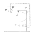
図1は、第1実施形態に係る位置検出システムの外観構成図である。位置検出システムは、ゲーム筐体10と、ゲーム筐体10の上方前面に設けられた赤外線カメラ20(反射光検出手段)の一部に相当)及びカラーカメラ21と、を含む。以下、赤外線カメラ20及びカラーカメラ21を、まとめてカメラ20,21と記載する場合がある。
<First Embodiment>
(1) Configuration (1-1) System Appearance FIG. 1 is an external configuration diagram of a position detection system according to the first embodiment. The position detection system includes a
ゲーム筐体10は、下記の要素を有している。
(a)ディスプレイ11(実スクリーンに相当):ディスプレイ11は、筐体上部中央に設けられ、後述するゲーム装置からの画像を出力する。
(b)ゲーム実行手段12:ゲーム実行手段12は、任意のゲームを実行し、実行中のゲームの画像を前記ディスプレイ11に出力する。本実施形態では、ゲーム実行手段12は、ディスプレイ11に表示される仮想オブジェクトに、プレイヤがボール(「被検出物」に相当)を投げて当てるゲームを実行する。
The
(A) Display 11 (corresponding to a real screen): The
(B) Game execution means 12: The game execution means 12 executes an arbitrary game and outputs an image of the game being executed to the
(c)画像解析ボード13(位置特定手段の一部、色彩特定手段に相当):画像解析ボード13は、赤外線カメラ20及びカラーカメラ21と接続され、両方のカメラで撮像された画像を解析する。具体的には、赤外線カメラ20の画像に基づいてボールにより生じる反射光の位置を特定し、その特定した位置における色彩を、カラーカメラ21の画像に基づいて特定する。
(C) Image analysis board 13 (corresponding to a part of position specifying means and color specifying means): The
(d)赤外線ランプ14(赤外線スクリーン生成手段):ディスプレイ11の直前に複数個設けられ、ディスプレイ11に沿って、かつディスプレイ11の全面に渡り、赤外線を照射する。これにより、ディスプレイ11の直前に平面状の赤外線網(赤外線スクリーン)が生成される。
赤外線カメラ20は、少なくともディスプレイ11全体が画角内に入るように設定され、連続的に撮像または所定時間間隔ΔT1で繰り返し撮像した映像を、画像解析ボード13に入力する。時間間隔ΔT1は、ディスプレイ11の画像が更新される間隔ΔT2以上(ΔT1≧ΔT2)であってよい。赤外線カメラ20は、カメラ(第1撮像手段に相当)と、カメラに取り付けられた赤外線フィルタ(図示せず)と、を含む。そのため、赤外線カメラ20には、赤外域の光が選択的に入力される。言い換えれば、赤外線カメラ20は、赤外線スクリーンを通過したボールによる反射光を選択的に撮像する。赤外線フィルタを用いず、赤外光のみを検出するカメラを、赤外線カメラ20として用いてもよい。赤外線カメラ20を構成するカメラとしては、CCDカメラやビデオカメラ、デジタルカメラなどを用いることができる。なお、撮像した画像の歪みを補正する手段があることが好ましい。例えば、非球面レンズなどの歪み補正レンズを用いてもよいし、ソフト的に画像の歪みを補正することも可能である。
(D) Infrared lamps 14 (infrared screen generating means): A plurality of
The
カラーカメラ21(第2撮像手段に相当)は、少なくともディスプレイ11全体が画角内に入るように設定され、連続的に撮像または所定時間間隔ΔT1で繰り返し撮像した映像を、画像解析ボード13に入力する。所定時間間隔で撮像を繰り返す場合、撮像のタイミングは、赤外線カメラ20の撮像のタイミングと同期していることが好ましい。前述の各種カメラをカラーカメラ21として用いても良い。また、赤外域の光を遮断するフィルタ、例えば可視光域の光を選択的に通過させるフィルタを前述のカメラに取り付けて、カラーカメラ21としても良い。このようなフィルタが取り付けられたカラーカメラ21は、ディスプレイ11に表示されている画像を選択的に撮像することができる。カラーカメラ21の画像において、赤外線カメラ20の画像に基づいて特定した位置の色彩を解析すれば、ボールの色を判別することができる。例えば、複数プレイヤによるゲームにおいてプレイヤ毎にボールの色が違う場合、プレイヤ毎に当たり判定を行うことが可能になる。
The color camera 21 (corresponding to the second imaging means) is set so that at least the
(1−2)画像解析ボード及びゲーム実行手段のハード構成
図2は、図1に示す画像解析ボード13及びゲーム実行手段12のハード構成を示す説明図である。図中、赤外線カメラ20を、IRカメラ20と表記している。
画像解析ボード13は、CPU131、ROM132、RAM133、通信ポート134、2つのフレームバッファ135a,b及び2つの画像処理部136a、bを有している。
(1-2) Hardware Configuration of Image Analysis Board and Game Execution Unit FIG. 2 is an explanatory diagram showing the hardware configuration of the
The
画像処理部136a,bは、カメラ20,21から入力された映像を、デジタルデータ化し、フレームバッファ135a、135bに展開する。より具体的には、画像処理部136a,bは、1)入力される映像のA/D変換、2)フレームバッファ134a,bに格納されるべきメモリー空間へのアドレス生成及びデジタルデータ化されたデータの書き込み、3)CPU131に対する、1フレーム分の上記処理1)及び処理2)完了の通知、を行う。フレームバッファ135aには、赤外線カメラ20が撮像した画像が展開される。フレームバッファ135bには、カラーカメラ21が撮像した画像が展開される。CPU131は、ROM132に記憶された画像処理プログラムを読み出し、RAM133を作業領域として用いながら、フレームバッファ135aに書き込まれた画像に基づいて、ボールの反射光の位置を特定する。また、CPU131は、フレームバッファ135bに書き込まれた画像に基づいて、反射光の位置における色情報を特定する。CPU131が行う画像解析処理については、詳細を後述する。CPU131は、通信ポート134を介し、特定した位置情報や色情報を、ゲーム実行手段12のバッファ124に書き込む。
The
ゲーム実行手段12は、下記(a)〜(e)の要素を有している。
(a)CPU121:後述するROM123に記憶されている制御プログラムを実行する。
(b)RAM122:各種変数やパラメータなどを一時的に記憶する。
(c)ROM123:制御プログラムや各種パラメータなどを記憶する。
(d)通信ポート(バッファ)124:通信ケーブル、例えばRS232Cを介し、画像解析ボード13からのデータを受信し、記憶する。
(e)描画処理部125:ディスプレイ11に表示する画像データを生成する。
The game execution means 12 has the following elements (a) to (e).
(A) CPU 121: executes a control program stored in a
(B) RAM 122: temporarily stores various variables and parameters.
(C) ROM 123: Stores control programs and various parameters.
(D) Communication port (buffer) 124: Receives and stores data from the
(E) Drawing processing unit 125: Generates image data to be displayed on the
また、上述した要素の他に、ゲーム実行手段12は、スピーカ、音声再生部、入力操作部、コイン受付部と接続されている(図示せず)。スピーカは、ゲーム実行中やデモ画面表示中のサウンドを出力する。音声再生部は、スピーカに出力させるためのサウンドデータを生成する。入力操作部は、ジョイスティックや操作ボタンなどから構成され、プレイヤの指示入力を受け付ける。コイン受付部は、挿入されるコインによるクレジットを受け付ける。 In addition to the elements described above, the game execution means 12 is connected to a speaker, a sound reproduction unit, an input operation unit, and a coin reception unit (not shown). The speaker outputs sound while the game is running or the demonstration screen is displayed. The sound reproducing unit generates sound data to be output to the speaker. The input operation unit includes a joystick, operation buttons, and the like, and accepts an instruction input from the player. The coin accepting unit accepts credit from the inserted coin.
上記のように構成されたゲーム実行手段12は、ROM123に記憶された制御プログラムに従い、ゲームを実行する。
(1−3)赤外線スクリーンとディスプレイとの位置関係
図3(a)は、赤外線スクリーンとディスプレイ11との位置関係を示す説明図である。赤外線スクリーンSIRは、ディスプレイ11の表示面と赤外線カメラ20との間に位置している。言い換えれば、ディスプレイ11は、赤外線スクリーンSIRを挟んで赤外線カメラ20と反対側に設置される。
The game execution means 12 configured as described above executes the game according to the control program stored in the
(1-3) Positional Relationship Between Infrared Screen and Display FIG. 3A is an explanatory diagram showing a positional relationship between the infrared screen and the
赤外線スクリーンSIRとディスプレイ11の表示面とは、近傍に位置することが好ましい。赤外線スクリーンSIRとディスプレイ11の表示面とを間近に設置することにより、ディスプレイ表示面のどこに物体が当たったのかを、実質的に特定することができる。さらに詳しくは、赤外線スクリーンSIRをディスプレイ11の表示面直前に形成することにより、ボールによる赤外線の反射をディスプレイの直前で生じさせる。赤外線スクリーンSIRとディスプレイ11の表示面とが近ければ近いほど、ボールがディスプレイ11に当たる位置と反射位置とのずれを小さくすることができる。
The infrared screen SIR and the display surface of the
より好ましくは、赤外線スクリーンSIRとディスプレイ11の表示面との距離Gは、ボールの最大長、すなわち直径を超えないように調整されていることが好ましい。このように両者の距離を調整しておくと、ディスプレイ11の表示面に当たって跳ね返ったボールによる赤外線の再反射を防止できる。
さらに、赤外線スクリーンSIRは、ディスプレイ11の表示面以上の大きさ、すなわちディスプレイ11の表示面と同一かそれより大きく、表示面を覆うことが好ましい。赤外線スクリーンSIRの面が、ボールの位置を検出可能な領域を決定するからである。逆に、赤外線スクリーンSIRがディスプレイ11の表示面より小さい形態もあり得る。この形態では、ボールがディスプレイ11の外側に投げられたことを検出し、その検出結果をゲームに反映させることができる。例えば、ディスプレイ11の外側にボールが投げられたら、減点などのペナルティをプレイヤに課すことが考えられる。
More preferably, the distance G between the infrared screen SIR and the display surface of the
Further, the infrared screen SIR is preferably larger than the display surface of the
(1−4)赤外線スクリーンの生成
図3(b)は、複数の赤外線ランプ14の配置例を示す。複数の赤外線ランプ14は、空間内の任意の矩形状平面の周縁の少なくとも一部に配置されている。この例では、ディスプレイの表示面に沿う矩形状平面の周縁に沿って、複数の赤外線ランプ14が等間隔に配置されている。
(1-4) Generation of Infrared Screen FIG. 3B shows an arrangement example of a plurality of
複数の赤外線ランプ14は、ディスプレイの表示面に沿う方向に、指向性を持って赤外線を照射する。より詳しくは、赤外線ランプ14から照射される赤外線の光軸は、前記矩形状平面上に位置し、赤外線の照射方向はその矩形状平面に含まれる。赤外線ランプ14からの赤外線にこのような指向性を持たせることで、赤外線スクリーンの厚みが小さくなる。これはすなわち、赤外線スクリーンを通過するボールにより生じる反射位置と、実際にボールがディスプレイに当たる位置とのずれを小さくすることにつながる。ひいては、ボールの位置検出の正確性を高めることができる。また、反射光の発光時間を短くすることができるため、ボールが赤外線スクリーンに当たるタイミングと反射光の発光タイミングとのずれを小さくすることができる。
The plurality of
複数の赤外線ランプ14は、少なくとも2辺に沿って配置されていることが好ましい。対向する2辺に沿ってでもよいし、交差する2辺に沿って配置されていても良い。
上記構成により、複数の赤外線ランプ14は、矩形状の赤外線スクリーンを形成する。この赤外線スクリーンを通過するボールには、少なくとも2方向から赤外線がほぼ均等に照射される。そのため、複数のボールがスクリーンを同時に通過する場合であっても、あるボールが他のボールの陰になりにくく、複数のボール全てにまんべんなく均等に赤外線を照射することができる。
The plurality of
With the above configuration, the plurality of
なお、赤外線ランプ14の間隔は、必ずしも等間隔でなくても良いが、等間隔であれば、赤外線スクリーンにおいて赤外線の強度を均一化することができる。
(2)ゲームでの具体例
図4、図5、図6は、ゲーム実行手段12が実行するゲームの一例を示す画面例である。このゲームでは、空から振ってくる隕石が、ウサギが住む建物に当たらないよう、隕石に向かってプレイヤがボールを投げ、隕石を粉砕する。画面上部の各ウサギに対応する位置には、ウサギの残りライフが数字で示されている。隕石によりウサギがダメージを受けるたびに、ウサギの残りライフは減少する。隕石がウサギに当たると、残存ライフがゼロでなくてもゲームオーバーとなる(図5参照)。この例では、4匹のウサギが居るので、最大4人のプレイヤがそれぞれのウサギを救うために参戦することができる。ゲームの終盤に、巨大隕石が落ちてくるので、これが地上に着くまでに所定数のボールを巨大隕石に命中させれば、プレイヤはゲームを続行することができる(図6参照)。
Note that the intervals of the
(2) Specific Example in Game FIGS. 4, 5, and 6 are screen examples showing an example of a game executed by the game execution means 12. FIG. In this game, the player throws the ball toward the meteorite and crushes the meteorite so that the meteorite swinging from the sky does not hit the building where the rabbit lives. In the position corresponding to each rabbit at the top of the screen, the remaining life of the rabbit is indicated by a number. Each time a rabbit is damaged by a meteorite, the remaining life of the rabbit decreases. If the meteorite hits the rabbit, the game is over even if the remaining life is not zero (see FIG. 5). In this example, there are four rabbits, so a maximum of four players can participate to save each rabbit. Since the huge meteorite falls at the end of the game, the player can continue the game by hitting the huge meteorite with a predetermined number of balls before it reaches the ground (see FIG. 6).
このゲームを行うゲーム実行手段12は、画像解析ボード13が特定したボールの位置に基づいて、ボールと隕石との当たり判定を行う。当たり判定の結果、ボールが隕石に当たっていれば、隕石を粉砕する。
(3)処理
(3−1)システム全体の処理
図7は、位置検出システム全体が行う処理の流れの一例を示す説明図である。この図は、画像解析ボード13が実行する画像解析処理の流れの一例も併せて示す。
The game execution means 12 for playing this game determines whether the ball is in contact with the meteorite based on the position of the ball specified by the
(3) Processing (3-1) Overall System Processing FIG. 7 is an explanatory diagram showing an example of the flow of processing performed by the entire position detection system. This figure also shows an example of the flow of image analysis processing executed by the
まず、赤外線カメラ20及びカラーカメラ21が実行する処理について説明する。赤外線カメラ20及びカラーカメラ21が行う処理は同じであるので、以下では両者を単にカメラ20,21と記載する。
カメラ20,21は、連続的に撮像を行い(#1)、映像信号を画像解析ボード13に転送する(#2)。
First, processing executed by the
The
次に、画像解析ボード13が実行する処理について説明する。画像処理部136a,bは、カメラ20,21から映像信号を受信し、映像信号をデジタルデータ化し、フレームバッファ135a,bに展開する(#11)。
CPU131は、フレームバッファ135aに展開された画像データを、ドット単位で、所定の閾値を基準に二値化し(#12)、赤外線の輝度の高い部分の選別をドット単位で行う(#13)。CPU131は、選別した輝度の高い部分、すなわち1以上の高輝度ドットからなる集合体それぞれについて、その集合体の面積を算出する(#14)。さらにCPU131は、算出した面積それぞれについて所定の範囲の大きさか否かを判断し(#15)、所定の大きさを有する高輝度ドットの集合体があれば、各高輝度集合体の重心座標を求める(#16)。次いで、CPU131は、重心座標を求めた集合体の円形度が所定の範囲内か否かを判断する(#17)。例えば、求めた重心座標を中心とする所定の半径の円内に、高輝度のドットが所定の範囲の割合で存在していれば、その集合体は円形であると判断することができる。
Next, processing executed by the
The
次いで、CPU131は、円形であると判断した高輝度集合体をボールの画像であるとみなし、フレームバッファ135aにおけるその重心座標を、フレームバッファ135bの座標に変換する。この座標変換は、フレームバッファ135a,b間で座標のずれがある場合に行う。さらに、CPU131は、変換して得られた座標位置の画像データから色情報を読み出す(#18)。その後、CPU131は、ボールの重心座標及び色情報を、ゲーム実行手段12のバッファ124に書き込む。
Next, the
次にゲーム実行手段12が実行する処理について説明する。ゲーム実行手段12のCPU121は、所定時間ΔT2が経過する毎にバッファ124を参照し、最新の位置情報及び色情報を読み出す(#21,#22)。読み出した情報は、ゲームの当たり判定に用いられる(#23)。ゲーム実行手段12は、例えば1/60sec毎にこの処理を行うことにより、バッファ124中に書き込まれた位置情報を用いてゲーム中での当たり判定を行う。
Next, processing executed by the game execution means 12 will be described. The
(3−2)ゲーム実行手段の処理
図8は、ゲーム実行手段12が行うゲーム処理の流れの一例を示すフローチャートである。ゲーム実行手段12のCPU121は、電源を投入されると、以下の処理を開始する。
ステップS1〜S2:CPU121は、でも画面をディスプレイに出力しながら、コインが投入されるのを待機する(S1)。コインが投入されると(S2)、ステップS3に移行する。
(3-2) Process of Game Execution Unit FIG. 8 is a flowchart showing an example of the game process flow performed by the
Steps S1 to S2: The
ステップS3:CPU121は、ROM123に記憶されているゲームプログラムを実行する。この実行に当たり、CPU121は、バッファ124を必要なタイミングで参照し、参照した時点でバッファ124に書き込まれている位置情報や色情報を、ゲームの処理に利用する。
ステップS4〜S5:CPU121は、ゲームが終了するまでゲームを実行し(S4)、ゲームが終了すると、ゲームのクリアによる終了なのか、それともゲームオーバーによる終了なのかを判断する(S5)。
Step S3: The
Steps S4 to S5: The
ステップS6:CPU121は、ゲームを続行するか否かの選択をプレイヤから受け付け、続行する場合は再び前記ステップS3に戻って新たなゲームを実行する。続行しない場合、及び前記ステップS4でゲームオーバーになった場合、前記ステップS1に戻り、でも画面を表示する。
本実施形態を用いれば、ゲームにおいて、プレイヤがディスプレイに向かって投げつけるボールが、ディスプレイのどこに当たったのかを、正確に検出できる。しかも、複数のボールが同時にディスプレイに当たった場合でも、各ボールの当たり位置をそれぞれ特定することができる。ボールによる反射光が、ディスプレイの直前で生じるため、反射光の生じる位置と、ボールがディスプレイに当たる位置と、のずれを押さえることができる。反射光が生じるタイミングと、ボールがディスプレイに当たるタイミングと、のずれも押さえることができる。そのため、検出結果に基づいて、ゲーム空間中の仮想オブジェクトとの当たり判定を行っても、違和感が生じることがない。
Step S6: The
By using this embodiment, it is possible to accurately detect where the ball that the player throws toward the display hits in the game. In addition, even when a plurality of balls hit the display at the same time, it is possible to specify the hit position of each ball. Since the light reflected by the ball is generated immediately before the display, it is possible to suppress a deviation between the position where the reflected light is generated and the position where the ball hits the display. The deviation between the timing at which the reflected light is generated and the timing at which the ball hits the display can be suppressed. Therefore, even if the hit determination with the virtual object in the game space is performed based on the detection result, there is no sense of incongruity.
<他の実施形態>
(A)本発明の位置検出方法は、赤外光でなくとも、可視光以外の波長の光を用いて実現可能である。ディスプレイからの可視光以外の波長の光をカメラに選択的に入力できれば、ディスプレイに表示される映像とボールの反射光との分離を行うことができるからである。
<Other embodiments>
(A) The position detection method of the present invention can be realized using light having a wavelength other than visible light, not infrared light. This is because if light of a wavelength other than visible light from the display can be selectively input to the camera, the image displayed on the display and the reflected light of the ball can be separated.
(B)前記実施形態では赤外線カメラ20及びカラーカメラ21をそれぞれ1台ずつ用いているが、必ずしも1台ずつでなくともよい。例えば、ディスプレイが大きすぎて1台のカメラの画角に収まりきらない場合、複数の赤外線カメラ20及びカラーカメラ21を用いてもよい。
(C)図9は、赤外線ランプ14の別の配置例を示す。赤外線ランプ14の配置は、前述の例に限定されない。赤外線スクリーン内を通過する複数の物体に均一に赤外線を照射できるように、赤外線ランプ14を配置すればよい。赤外線スクリーンを形成しようとする矩形状平面の少なくとも2隅に、90度の範囲内で、かつその平面上に光軸を持つ赤外線IRを照射する赤外線ランプ14’を取り付けてもよい。この赤外線ランプ14’を矩形状平面の2隅に取り付ける場合には、対角線上にある2隅に取り付けることが好ましい。その方が、赤外線スクリーンを通過するボールに均等に赤外線を照射しやすいからである。
(B) In the embodiment, one
(C) FIG. 9 shows another arrangement example of the
(D)画像解析ボード13は、反射光が生じたタイミング、例えば時刻情報やタイムスタンプを検出してもよい。これにより、ボールなどの物体が、どのような順序で赤外線スクリーンを通過したのかを特定することができる。
また、タイミングの検出により、物体が赤外線スクリーン上に描いた軌跡を検出することもできる。例えば、プレイヤが剣を操作して敵キャラクタと戦う戦闘ゲームにおいて、プレイヤが剣を用いて特定のパターン、例えば十文字を描いたかどうかを、赤外線スクリーン上での剣の軌跡に基づいて判断することができる。
(D) The
Further, the locus drawn by the object on the infrared screen can be detected by detecting the timing. For example, in a battle game in which a player operates a sword and fights an enemy character, it can be determined based on the trajectory of the sword on the infrared screen whether the player has drawn a specific pattern, such as a cross, using the sword. it can.
(E)前記実施形態では、ゲームの例を用いて説明したが、本発明はゲーム以外の分野にも適用可能である。例えば、陸上競技や競馬での勝敗の判定に用いてもよい。この場合は、画像解析ボード13は、前述のタイミングの検出を行うことがさらに好ましい。
また、ゲームに適用する場合、前述のゲームだけでなく、他の様々なゲームに適用可能である。また、検出する物体も、ボールだけでなく、例えば弓矢、BB弾、差し棒であってもよいし、プレイヤの体の一部であってもよい。例えば、プレイヤが塗料を塗布したグローブをはめて行う格闘ゲームにおいて、グローブの位置を検出することもできる。
(E) Although the above embodiment has been described using an example of a game, the present invention can also be applied to fields other than games. For example, it may be used for determination of winning or losing in athletics or horse racing. In this case, it is more preferable that the
Moreover, when applied to a game, it is applicable not only to the above-described game but also to various other games. Further, the object to be detected is not limited to the ball, but may be, for example, a bow and arrow, a BB bullet, a insertion rod, or a part of the player's body. For example, the position of the glove can be detected in a fighting game performed by the player wearing a glove with paint applied.
(F)前記位置検出システムが実行する位置検出方法は、本発明の範囲に含まれる。また、この位置検出方法に用いられる位置特定方法、この方法を実行するプログラム及びそのプログラムを記録したコンピュータ読み取り記録媒体は、本発明の範囲に含まれる。ここでプログラムには、記録媒体に記憶されているものもダウンロード可能なものが含まれる。また記録媒体としては、コンピュータが読み書き可能なフレキシブルディスク、ハードディスク、半導体メモリ、CD−ROM、DVD、光磁気ディスク(MO)、その他のものが挙げられる。 (F) The position detection method executed by the position detection system is included in the scope of the present invention. Further, a position specifying method used in this position detecting method, a program for executing this method, and a computer-readable recording medium recording the program are included in the scope of the present invention. Here, the programs include those stored in the recording medium and those that can be downloaded. Examples of the recording medium include a computer readable / writable flexible disk, hard disk, semiconductor memory, CD-ROM, DVD, magneto-optical disk (MO), and the like.
本発明は、空間での物体の位置を検出するあらゆる分野に適用でき、ゲーム分野に好適に適用することができる。 The present invention can be applied to all fields for detecting the position of an object in space, and can be suitably applied to the game field.
10:ゲーム筐体
20:赤外線カメラ
21:カラーカメラ
11:ディスプレイ
12:ゲーム実行手段
13:画像解析ボード
14:赤外線ランプ
10: Game case 20: Infrared camera 21: Color camera 11: Display 12: Game execution means 13: Image analysis board 14: Infrared lamp
Claims (8)
任意の複数の被検出物が前記赤外線スクリーンを通過することによる前記赤外線スクリーン上での赤外線の反射を選択的に検出する反射光検出手段と、
前記反射光検出手段が検出した赤外線の複数の反射位置を、前記赤外線スクリーン上で特定する位置特定手段と、
前記赤外線スクリーンを挟んで前記反射光検出手段と反対側に、前記赤外線スクリーンに沿ってその近傍に設けられている実スクリーンと、を有し、
前記反射光検出手段は、
少なくとも前記実スクリーン全体が画角内に入るように設定され、所定時間間隔で撮像を繰り返す第1撮像手段と、
前記第1撮像手段に取り付けられ、前記第1撮像手段に入力される光を選択する赤外線フィルタと、を含み、
前記位置特定手段は、前記第1撮像手段が撮像した各画像を解析することにより、前記赤外線スクリーン上での前記被検出物による赤外線の反射位置を特定する、
ことを特徴とする位置検出システム。 An infrared screen generating means for generating a planar infrared screen;
Reflected light detection means for selectively detecting reflection of infrared rays on the infrared screen caused by any plurality of detection objects passing through the infrared screen;
A plurality of reflection positions of infrared said reflected light detecting unit detects a position specifying means for specifying on the infrared screen,
On the opposite side of the reflected light detection means across the infrared screen, an actual screen provided in the vicinity along the infrared screen ,
The reflected light detection means includes
First imaging means that is set so that at least the entire real screen falls within the angle of view, and repeats imaging at predetermined time intervals;
An infrared filter that is attached to the first imaging means and that selects light input to the first imaging means;
The position specifying means specifies an infrared reflection position by the detected object on the infrared screen by analyzing each image picked up by the first image pickup means.
A position detection system characterized by that.
前記実スクリーンは、前記ゲーム実行手段と接続され、前記ゲーム実行手段からの画像を出力するディスプレイであることを特徴とする、請求項1〜4のいずれかに記載の位置検出システム。 A game execution means for executing an arbitrary game;
The actual screen, which is connected with the game execution unit, characterized in that it is a display for outputting an image from the game execution means, the position detecting system according to any of claims 1-4.
前記第1撮像手段及び前記第2撮像手段が撮像した各画像を解析することにより、前記被検出物の色を判別する色彩特定手段と、
をさらに有することを特徴とする、請求項1〜5に記載の位置検出システム。 A second imaging means that is set so that at least the entire real screen falls within the angle of view, and repeats imaging of color images at predetermined time intervals;
Color specifying means for determining the color of the detected object by analyzing each image captured by the first imaging means and the second imaging means;
Characterized by further comprising a position detection system according to claim 1-5.
任意の複数の被検出物が前記赤外線スクリーンを通過することによる前記赤外線スクリーン上での赤外線の反射を、反射光検出手段により選択的に検出する反射光検出ステップと、
前記反射光検出ステップで検出された赤外線の複数の反射位置を、前記赤外線スクリーン上で特定する位置特定ステップと、を有し、
前記反射光検出ステップは、
少なくとも実スクリーン全体が画角内に入るように設定され、所定時間間隔で撮像を繰り返す第1撮像ステップと、
前記第1撮像ステップで撮像される光を赤外線フィルタで選択するフィルタリングステップと、を含み、
前記位置特定ステップは、前記第1撮像ステップで撮像した各画像を解析することにより、前記赤外線スクリーン上での前記被検出物による赤外線の反射位置を特定し、
前記実スクリーンは、前記赤外線スクリーンを挟んで前記反射光検出手段と反対側に、前記赤外線スクリーンに沿ってその近傍に設けられている、ことを特徴とする位置検出方法。 An infrared screen generating step for generating a planar infrared screen;
A reflected light detecting step of selectively detecting reflection of infrared rays on the infrared screen by passing a plurality of arbitrary detection objects through the infrared screen;
A plurality of reflection positions of infrared rays detected by the reflected light detecting step, anda position specifying step of specifying on the infrared screen,
The reflected light detection step includes
A first imaging step that is set so that at least the entire real screen falls within the angle of view, and repeats imaging at predetermined time intervals;
A filtering step of selecting the light imaged in the first imaging step with an infrared filter,
The position specifying step specifies an infrared reflection position by the detected object on the infrared screen by analyzing each image captured in the first imaging step,
The position detection method according to claim 1, wherein the actual screen is provided on the opposite side of the reflected light detection unit across the infrared screen and along the infrared screen .
Priority Applications (7)
| Application Number | Priority Date | Filing Date | Title |
|---|---|---|---|
| JP2005218132A JP3934658B2 (en) | 2005-07-28 | 2005-07-28 | Position detection system |
| PCT/JP2006/313818 WO2007013299A1 (en) | 2005-07-28 | 2006-07-12 | Position detection system |
| CN2006800211947A CN101198383B (en) | 2005-07-28 | 2006-07-12 | Position detection system |
| EP06780988A EP1908496A4 (en) | 2005-07-28 | 2006-07-12 | Position detection system |
| KR1020077024278A KR101017916B1 (en) | 2005-07-28 | 2006-07-12 | Position detection system |
| TW095125715A TW200708327A (en) | 2005-07-28 | 2006-07-13 | Position detection system |
| US12/021,038 US7453582B2 (en) | 2005-07-28 | 2008-01-28 | Position detection system |
Applications Claiming Priority (1)
| Application Number | Priority Date | Filing Date | Title |
|---|---|---|---|
| JP2005218132A JP3934658B2 (en) | 2005-07-28 | 2005-07-28 | Position detection system |
Publications (2)
| Publication Number | Publication Date |
|---|---|
| JP2007029478A JP2007029478A (en) | 2007-02-08 |
| JP3934658B2 true JP3934658B2 (en) | 2007-06-20 |
Family
ID=37683200
Family Applications (1)
| Application Number | Title | Priority Date | Filing Date |
|---|---|---|---|
| JP2005218132A Active JP3934658B2 (en) | 2005-07-28 | 2005-07-28 | Position detection system |
Country Status (7)
| Country | Link |
|---|---|
| US (1) | US7453582B2 (en) |
| EP (1) | EP1908496A4 (en) |
| JP (1) | JP3934658B2 (en) |
| KR (1) | KR101017916B1 (en) |
| CN (1) | CN101198383B (en) |
| TW (1) | TW200708327A (en) |
| WO (1) | WO2007013299A1 (en) |
Cited By (1)
| Publication number | Priority date | Publication date | Assignee | Title |
|---|---|---|---|---|
| US9465480B2 (en) | 2013-02-01 | 2016-10-11 | Seiko Epson Corporation | Position detection apparatus, adjustment method, and adjustment program |
Families Citing this family (51)
| Publication number | Priority date | Publication date | Assignee | Title |
|---|---|---|---|---|
| JP5015270B2 (en) * | 2007-02-15 | 2012-08-29 | クアルコム,インコーポレイテッド | Input using flashing electromagnetic radiation |
| JP2008306512A (en) * | 2007-06-08 | 2008-12-18 | Nec Corp | Information providing system |
| JP4745316B2 (en) * | 2007-11-07 | 2011-08-10 | シャープ株式会社 | Display system and indication position detection method |
| EP2335138A4 (en) * | 2008-08-15 | 2012-12-19 | Qualcomm Inc | Enhanced multi-touch detection |
| US9635285B2 (en) | 2009-03-02 | 2017-04-25 | Flir Systems, Inc. | Infrared imaging enhancement with fusion |
| US9843742B2 (en) | 2009-03-02 | 2017-12-12 | Flir Systems, Inc. | Thermal image frame capture using de-aligned sensor array |
| US9235876B2 (en) | 2009-03-02 | 2016-01-12 | Flir Systems, Inc. | Row and column noise reduction in thermal images |
| US9998697B2 (en) | 2009-03-02 | 2018-06-12 | Flir Systems, Inc. | Systems and methods for monitoring vehicle occupants |
| US10757308B2 (en) | 2009-03-02 | 2020-08-25 | Flir Systems, Inc. | Techniques for device attachment with dual band imaging sensor |
| USD765081S1 (en) | 2012-05-25 | 2016-08-30 | Flir Systems, Inc. | Mobile communications device attachment with camera |
| US9674458B2 (en) | 2009-06-03 | 2017-06-06 | Flir Systems, Inc. | Smart surveillance camera systems and methods |
| US10244190B2 (en) | 2009-03-02 | 2019-03-26 | Flir Systems, Inc. | Compact multi-spectrum imaging with fusion |
| US9451183B2 (en) | 2009-03-02 | 2016-09-20 | Flir Systems, Inc. | Time spaced infrared image enhancement |
| US9473681B2 (en) | 2011-06-10 | 2016-10-18 | Flir Systems, Inc. | Infrared camera system housing with metalized surface |
| US9756264B2 (en) | 2009-03-02 | 2017-09-05 | Flir Systems, Inc. | Anomalous pixel detection |
| US9208542B2 (en) | 2009-03-02 | 2015-12-08 | Flir Systems, Inc. | Pixel-wise noise reduction in thermal images |
| WO2012170949A2 (en) | 2011-06-10 | 2012-12-13 | Flir Systems, Inc. | Non-uniformity correction techniques for infrared imaging devices |
| US9986175B2 (en) | 2009-03-02 | 2018-05-29 | Flir Systems, Inc. | Device attachment with infrared imaging sensor |
| US9948872B2 (en) | 2009-03-02 | 2018-04-17 | Flir Systems, Inc. | Monitor and control systems and methods for occupant safety and energy efficiency of structures |
| US9517679B2 (en) | 2009-03-02 | 2016-12-13 | Flir Systems, Inc. | Systems and methods for monitoring vehicle occupants |
| US9843743B2 (en) | 2009-06-03 | 2017-12-12 | Flir Systems, Inc. | Infant monitoring systems and methods using thermal imaging |
| US9716843B2 (en) | 2009-06-03 | 2017-07-25 | Flir Systems, Inc. | Measurement device for electrical installations and related methods |
| US9819880B2 (en) | 2009-06-03 | 2017-11-14 | Flir Systems, Inc. | Systems and methods of suppressing sky regions in images |
| US10091439B2 (en) | 2009-06-03 | 2018-10-02 | Flir Systems, Inc. | Imager with array of multiple infrared imaging modules |
| US9292909B2 (en) | 2009-06-03 | 2016-03-22 | Flir Systems, Inc. | Selective image correction for infrared imaging devices |
| US9756262B2 (en) | 2009-06-03 | 2017-09-05 | Flir Systems, Inc. | Systems and methods for monitoring power systems |
| US9706138B2 (en) | 2010-04-23 | 2017-07-11 | Flir Systems, Inc. | Hybrid infrared sensor array having heterogeneous infrared sensors |
| US9848134B2 (en) | 2010-04-23 | 2017-12-19 | Flir Systems, Inc. | Infrared imager with integrated metal layers |
| US9207708B2 (en) | 2010-04-23 | 2015-12-08 | Flir Systems, Inc. | Abnormal clock rate detection in imaging sensor arrays |
| JP5307108B2 (en) * | 2010-10-29 | 2013-10-02 | 株式会社コナミデジタルエンタテインメント | Detection system, electronic blackboard apparatus to which the detection system is applied, its control method, and computer program |
| US10079982B2 (en) | 2011-06-10 | 2018-09-18 | Flir Systems, Inc. | Determination of an absolute radiometric value using blocked infrared sensors |
| KR101808375B1 (en) | 2011-06-10 | 2017-12-12 | 플리어 시스템즈, 인크. | Low power and small form factor infrared imaging |
| US10169666B2 (en) | 2011-06-10 | 2019-01-01 | Flir Systems, Inc. | Image-assisted remote control vehicle systems and methods |
| US9509924B2 (en) | 2011-06-10 | 2016-11-29 | Flir Systems, Inc. | Wearable apparatus with integrated infrared imaging module |
| US9961277B2 (en) | 2011-06-10 | 2018-05-01 | Flir Systems, Inc. | Infrared focal plane array heat spreaders |
| US9235023B2 (en) | 2011-06-10 | 2016-01-12 | Flir Systems, Inc. | Variable lens sleeve spacer |
| US9058653B1 (en) | 2011-06-10 | 2015-06-16 | Flir Systems, Inc. | Alignment of visible light sources based on thermal images |
| US10051210B2 (en) | 2011-06-10 | 2018-08-14 | Flir Systems, Inc. | Infrared detector array with selectable pixel binning systems and methods |
| US10841508B2 (en) | 2011-06-10 | 2020-11-17 | Flir Systems, Inc. | Electrical cabinet infrared monitor systems and methods |
| US9900526B2 (en) | 2011-06-10 | 2018-02-20 | Flir Systems, Inc. | Techniques to compensate for calibration drifts in infrared imaging devices |
| US9143703B2 (en) | 2011-06-10 | 2015-09-22 | Flir Systems, Inc. | Infrared camera calibration techniques |
| US9706137B2 (en) | 2011-06-10 | 2017-07-11 | Flir Systems, Inc. | Electrical cabinet infrared monitor |
| EP2719166B1 (en) | 2011-06-10 | 2018-03-28 | Flir Systems, Inc. | Line based image processing and flexible memory system |
| US10389953B2 (en) | 2011-06-10 | 2019-08-20 | Flir Systems, Inc. | Infrared imaging device having a shutter |
| US9811884B2 (en) | 2012-07-16 | 2017-11-07 | Flir Systems, Inc. | Methods and systems for suppressing atmospheric turbulence in images |
| JP6081830B2 (en) * | 2013-03-12 | 2017-02-15 | 新日本無線株式会社 | Position detection device using a reflective photosensor |
| US9973692B2 (en) | 2013-10-03 | 2018-05-15 | Flir Systems, Inc. | Situational awareness by compressed display of panoramic views |
| US11297264B2 (en) | 2014-01-05 | 2022-04-05 | Teledyne Fur, Llc | Device attachment with dual band imaging sensor |
| JP2018005806A (en) * | 2016-07-08 | 2018-01-11 | 株式会社スクウェア・エニックス | Position specification program, computer device, position specification method, and position specification system |
| CN112915523B (en) * | 2019-01-03 | 2022-11-18 | 上海亿湾特训练设备科技有限公司 | Shooting distinguishing method and system |
| CN113587734A (en) * | 2021-07-12 | 2021-11-02 | 孙立峰 | Visual identification target scoring method based on near-infrared light imaging |
Family Cites Families (14)
| Publication number | Priority date | Publication date | Assignee | Title |
|---|---|---|---|---|
| JPS596078A (en) * | 1982-06-30 | 1984-01-13 | 美津濃株式会社 | Pitching exerciser |
| US5328190A (en) * | 1992-08-04 | 1994-07-12 | Dart International, Inc. | Method and apparatus enabling archery practice |
| US5649706A (en) * | 1994-09-21 | 1997-07-22 | Treat, Jr.; Erwin C. | Simulator and practice method |
| JP3183820B2 (en) * | 1996-02-22 | 2001-07-09 | 住友ゴム工業株式会社 | Flying object position measuring device and position measuring method |
| JP3794180B2 (en) | 1997-11-11 | 2006-07-05 | セイコーエプソン株式会社 | Coordinate input system and coordinate input device |
| JP2000148375A (en) * | 1998-11-11 | 2000-05-26 | Seiko Epson Corp | Input system and projection type display system |
| JP2001350576A (en) | 2000-06-08 | 2001-12-21 | Clarion Co Ltd | Visual interface |
| US8287374B2 (en) * | 2000-07-07 | 2012-10-16 | Pryor Timothy R | Reconfigurable control displays for games, toys, and other applications |
| TW539568B (en) | 2001-04-27 | 2003-07-01 | Tvio Technology Co Ltd | Location information detection system and game machine using the location information detection system |
| JP3662863B2 (en) | 2001-07-31 | 2005-06-22 | Necパーソナルプロダクツ株式会社 | Light gun, target box, shooting box, and light gun shooting system |
| JP3920067B2 (en) | 2001-10-09 | 2007-05-30 | 株式会社イーアイティー | Coordinate input device |
| JP3867205B2 (en) * | 2002-08-30 | 2007-01-10 | カシオ計算機株式会社 | Pointed position detection device, pointed position detection system, and pointed position detection method |
| JP2004101317A (en) * | 2002-09-09 | 2004-04-02 | Matsushita Electric Ind Co Ltd | Position detecting method, position detector, and electronic blackboard |
| JP2005052306A (en) | 2003-08-01 | 2005-03-03 | Sony Corp | Position detection system |
-
2005
- 2005-07-28 JP JP2005218132A patent/JP3934658B2/en active Active
-
2006
- 2006-07-12 KR KR1020077024278A patent/KR101017916B1/en not_active IP Right Cessation
- 2006-07-12 CN CN2006800211947A patent/CN101198383B/en active Active
- 2006-07-12 WO PCT/JP2006/313818 patent/WO2007013299A1/en active Application Filing
- 2006-07-12 EP EP06780988A patent/EP1908496A4/en not_active Withdrawn
- 2006-07-13 TW TW095125715A patent/TW200708327A/en unknown
-
2008
- 2008-01-28 US US12/021,038 patent/US7453582B2/en active Active
Cited By (1)
| Publication number | Priority date | Publication date | Assignee | Title |
|---|---|---|---|---|
| US9465480B2 (en) | 2013-02-01 | 2016-10-11 | Seiko Epson Corporation | Position detection apparatus, adjustment method, and adjustment program |
Also Published As
| Publication number | Publication date |
|---|---|
| TWI307637B (en) | 2009-03-21 |
| KR101017916B1 (en) | 2011-03-04 |
| CN101198383A (en) | 2008-06-11 |
| WO2007013299A1 (en) | 2007-02-01 |
| CN101198383B (en) | 2011-01-26 |
| US20080165342A1 (en) | 2008-07-10 |
| JP2007029478A (en) | 2007-02-08 |
| KR20070116901A (en) | 2007-12-11 |
| TW200708327A (en) | 2007-03-01 |
| US7453582B2 (en) | 2008-11-18 |
| EP1908496A1 (en) | 2008-04-09 |
| EP1908496A4 (en) | 2012-03-28 |
Similar Documents
| Publication | Publication Date | Title |
|---|---|---|
| JP3934658B2 (en) | Position detection system | |
| US8791901B2 (en) | Object tracking with projected reference patterns | |
| JP2681454B2 (en) | Shooting game device | |
| CN102449641A (en) | Color calibration for object tracking | |
| JP2007300985A (en) | Game program and game device | |
| JPWO2007037227A1 (en) | POSITION INFORMATION DETECTING DEVICE, POSITION INFORMATION DETECTING METHOD, AND POSITION INFORMATION DETECTING PROGRAM | |
| US8282104B2 (en) | Game system, detection program, and detection method | |
| US20050026703A1 (en) | Position detection system, game machine, program, and information storage medium | |
| JP5843217B2 (en) | GAME PROGRAM, GAME DEVICE, AND RECORDING MEDIUM CONTAINING GAME PROGRAM | |
| US8075379B2 (en) | Game device with cheating prevention function, and method and program for preventing cheating during a game | |
| JP5656387B2 (en) | Game device and game program for realizing the game device | |
| KR101395237B1 (en) | Compensating for blooming of a shape in an image | |
| JPH07306012A (en) | Measurement device of moving object | |
| JP2001062149A (en) | Spotlight position detection system, and simulator | |
| JP2001162049A (en) | Shooting game device, position detecting device, and information memory medium | |
| JP5638797B2 (en) | GAME DEVICE AND GAME PROGRAM | |
| JP2000189671A (en) | Shooting game device | |
| JP2573983B2 (en) | Recognition method of dice eyes used in game | |
| JP2007267850A (en) | Program, information storage medium, and image generating system | |
| JP4900914B2 (en) | Program, information storage medium, and image generation system | |
| JP2011130927A (en) | Game device | |
| JP2007267849A (en) | Program, information storage medium, and image generating system | |
| JP2000199698A (en) | Light beam irradiating position detecting device | |
| JP3418156B2 (en) | Shooting game apparatus, shooting game processing method, and information storage medium | |
| GB2467951A (en) | Detecting orientation of a controller from an image of the controller captured with a camera |
Legal Events
| Date | Code | Title | Description |
|---|---|---|---|
| A521 | Request for written amendment filed |
Free format text: JAPANESE INTERMEDIATE CODE: A523 Effective date: 20061120 |
|
| TRDD | Decision of grant or rejection written | ||
| A01 | Written decision to grant a patent or to grant a registration (utility model) |
Free format text: JAPANESE INTERMEDIATE CODE: A01 Effective date: 20070306 |
|
| A61 | First payment of annual fees (during grant procedure) |
Free format text: JAPANESE INTERMEDIATE CODE: A61 Effective date: 20070315 |
|
| R150 | Certificate of patent or registration of utility model |
Ref document number: 3934658 Country of ref document: JP Free format text: JAPANESE INTERMEDIATE CODE: R150 Free format text: JAPANESE INTERMEDIATE CODE: R150 |
|
| FPAY | Renewal fee payment (event date is renewal date of database) |
Free format text: PAYMENT UNTIL: 20100330 Year of fee payment: 3 |
|
| S531 | Written request for registration of change of domicile |
Free format text: JAPANESE INTERMEDIATE CODE: R313531 |
|
| FPAY | Renewal fee payment (event date is renewal date of database) |
Free format text: PAYMENT UNTIL: 20100330 Year of fee payment: 3 |
|
| R350 | Written notification of registration of transfer |
Free format text: JAPANESE INTERMEDIATE CODE: R350 |
|
| FPAY | Renewal fee payment (event date is renewal date of database) |
Free format text: PAYMENT UNTIL: 20110330 Year of fee payment: 4 |
|
| R250 | Receipt of annual fees |
Free format text: JAPANESE INTERMEDIATE CODE: R250 |
|
| FPAY | Renewal fee payment (event date is renewal date of database) |
Free format text: PAYMENT UNTIL: 20110330 Year of fee payment: 4 |
|
| FPAY | Renewal fee payment (event date is renewal date of database) |
Free format text: PAYMENT UNTIL: 20120330 Year of fee payment: 5 |
|
| R250 | Receipt of annual fees |
Free format text: JAPANESE INTERMEDIATE CODE: R250 |
|
| FPAY | Renewal fee payment (event date is renewal date of database) |
Free format text: PAYMENT UNTIL: 20130330 Year of fee payment: 6 |
|
| R250 | Receipt of annual fees |
Free format text: JAPANESE INTERMEDIATE CODE: R250 |
|
| FPAY | Renewal fee payment (event date is renewal date of database) |
Free format text: PAYMENT UNTIL: 20140330 Year of fee payment: 7 |
|
| R250 | Receipt of annual fees |
Free format text: JAPANESE INTERMEDIATE CODE: R250 |
|
| R250 | Receipt of annual fees |
Free format text: JAPANESE INTERMEDIATE CODE: R250 |
|
| R250 | Receipt of annual fees |
Free format text: JAPANESE INTERMEDIATE CODE: R250 |
|
| S802 | Written request for registration of partial abandonment of right |
Free format text: JAPANESE INTERMEDIATE CODE: R311802 |
|
| R250 | Receipt of annual fees |
Free format text: JAPANESE INTERMEDIATE CODE: R250 |
|
| R350 | Written notification of registration of transfer |
Free format text: JAPANESE INTERMEDIATE CODE: R350 |
|
| R250 | Receipt of annual fees |
Free format text: JAPANESE INTERMEDIATE CODE: R250 |
|
| R250 | Receipt of annual fees |
Free format text: JAPANESE INTERMEDIATE CODE: R250 |
|
| R250 | Receipt of annual fees |
Free format text: JAPANESE INTERMEDIATE CODE: R250 |
|
| R250 | Receipt of annual fees |
Free format text: JAPANESE INTERMEDIATE CODE: R250 |
|
| R250 | Receipt of annual fees |
Free format text: JAPANESE INTERMEDIATE CODE: R250 |
|
| R250 | Receipt of annual fees |
Free format text: JAPANESE INTERMEDIATE CODE: R250 |
|
| R250 | Receipt of annual fees |
Free format text: JAPANESE INTERMEDIATE CODE: R250 |
|
| R250 | Receipt of annual fees |
Free format text: JAPANESE INTERMEDIATE CODE: R250 |