JP3932012B2 - Installation method of solar cell module - Google Patents
Installation method of solar cell module Download PDFInfo
- Publication number
- JP3932012B2 JP3932012B2 JP2000194572A JP2000194572A JP3932012B2 JP 3932012 B2 JP3932012 B2 JP 3932012B2 JP 2000194572 A JP2000194572 A JP 2000194572A JP 2000194572 A JP2000194572 A JP 2000194572A JP 3932012 B2 JP3932012 B2 JP 3932012B2
- Authority
- JP
- Japan
- Prior art keywords
- solar cell
- cell module
- cylindrical member
- hollow
- cylindrical
- Prior art date
- Legal status (The legal status is an assumption and is not a legal conclusion. Google has not performed a legal analysis and makes no representation as to the accuracy of the status listed.)
- Expired - Fee Related
Links
Images


Classifications
-
- F—MECHANICAL ENGINEERING; LIGHTING; HEATING; WEAPONS; BLASTING
- F24—HEATING; RANGES; VENTILATING
- F24S—SOLAR HEAT COLLECTORS; SOLAR HEAT SYSTEMS
- F24S25/00—Arrangement of stationary mountings or supports for solar heat collector modules
-
- Y—GENERAL TAGGING OF NEW TECHNOLOGICAL DEVELOPMENTS; GENERAL TAGGING OF CROSS-SECTIONAL TECHNOLOGIES SPANNING OVER SEVERAL SECTIONS OF THE IPC; TECHNICAL SUBJECTS COVERED BY FORMER USPC CROSS-REFERENCE ART COLLECTIONS [XRACs] AND DIGESTS
- Y02—TECHNOLOGIES OR APPLICATIONS FOR MITIGATION OR ADAPTATION AGAINST CLIMATE CHANGE
- Y02E—REDUCTION OF GREENHOUSE GAS [GHG] EMISSIONS, RELATED TO ENERGY GENERATION, TRANSMISSION OR DISTRIBUTION
- Y02E10/00—Energy generation through renewable energy sources
- Y02E10/50—Photovoltaic [PV] energy
Description
【0001】
【発明の属する技術分野】
この発明は、電気絶縁性を有するフィルム基板上に形成された太陽電池を、電気絶縁性の保護材により封止するために、太陽電池の受光面側および非受光面側の双方に保護層を設けた太陽電池モジュールの設置方法に関する。
【0002】
【従来の技術】
現在、環境保護の立場から、クリーンなエネルギーの研究開発が進められている。中でも、太陽電池はその資源(太陽光)が無限であること、無公害であることから注目を集めている。同一基板上に形成された複数の太陽電池素子が、直列接続されてなる太陽電池(光電変換装置)の代表例は、薄膜太陽電池である。
【0003】
薄膜太陽電池は、薄型で軽量、製造コストの安さ、大面積化が容易であることなどから、今後の太陽電池の主流となると考えられ、電力供給用以外に、建物の屋根や窓などにとりつけて利用される業務用,一般住宅用にも需要が広がってきている。
【0004】
従来の薄膜太陽電池はガラス基板を用いていたが、軽量化、施工性、量産性においてプラスチックフィルムを用いたフレキシブルタイプの太陽電池の研究開発がすすめられている。このフレキシブル性を生かし、ロールツーロール方式の製造方法により大量生産が可能となった。
【0005】
上記の薄膜太陽電池モジュールとしては、電気絶縁性を有するフィルム基板上に形成された太陽電池を、電気絶縁性の保護材により封止するために、太陽電池の受光面側および非受光面側の双方に保護層を設けたものが知られている。
【0006】
上記太陽電池モジュールは、保護材がプラスチックのため、ねじれや引っ張り力に対する強度が弱く、このため施工時の外力によって破損したりするおそれがあった。そこで、特許第2651121号や特許第2719114号に記載されたように、太陽電池モジュールの裏面全体に補強板を設けたり、実開昭55−25383号公報に記載のように、非発電領域に補強材と電力リード線を兼用した構造のものが開発されている。
【0007】
また、太陽電池モジュールの屋根などへの設置方法としては、下記のような方法が知られている。樹脂の保護材で封止された太陽電池モジュールの設置方法としては、例えば、前記特許第2651121号公報に記載された方法が知られている。図10にその概略構成を示し、図10において920は屋根の野地板、910は野地板にボルトで取り付けられた太陽電池モジュール800の受け部材である。太陽電池モジュールは、太陽電池モジュールの補強板と充填材と透光フィルムとを、受光面と反対側に折り曲げたものとなし、太陽電池モジュールを設置する際には、この折り曲げ部を前記受け部材910に嵌合させて、太陽電池モジュールを固定する方法が採用されている。
【0008】
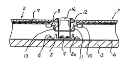
一方、ガラスカバー型太陽電池モジュールの設置方法としては、下記の方法が知られている。図11は太陽電池アレイの部分平面図、図12は図11のD−Dに沿った断面図である。太陽電池アレイ1は図示しない屋根面に太陽電池モジュール2を複数個、平面状に設置して構成しており、さらには屋根の野地板3の表面にルーフィング材4が敷かれ、固定部材5が木ネジ6などで野地板3に固定されている。太陽電池モジュール2は略四角形平板のガラス7の四辺がフレーム8で保持固定され、フレーム8は固定部材5にネジ9で固定されている。一方、端子箱10に接続されたケーブル11は、太陽電池モジュール2を固定部材5に取付ける際、フレーム8の貫通穴12を通して隣接する太陽電池モジュール2のケーブル11とジョイント13で電気的に直並列的に接続され、図示しないインバータに接続される。また隣接する太陽電池モジュール2のフレーム8にはカバー部材14が取付けられ、雨水が屋根裏に侵入するのを防止している。なお、固定部材5の突起部5aは万一、雨水が侵入しても野地板3に流入しない役目をなすもので図示はしないが、屋根傾斜面に沿って軒先側に流れて外に排出される。
【0009】
ところで、前記実開昭55−25383号公報に記載の太陽電池モジュールの場合、フレキシブル性がなく重量も増大する問題があり、特許第2651121号公報に記載された太陽電池モジュールの場合、全面補強故にモジュール重量が増大し、また、モジュールの設置方法と関連して、補強板と充填材と透光フィルムとを受光面と反対側に折り曲げる構造のため、作業性が悪く加工費用が嵩み、また、大型の曲げ加工設備を必要とするなど全体としてコストが増大する。さらに、太陽電池モジュールの寸法を小さくした場合、ある広さの太陽電池アレイを構築する場合に取付け回数が増えて、作業工数が増す。また太陽電池モジュール毎に端子やケーブルが必要になり、太陽電池モジュールのコストが、この観点からも増大する。
【0010】
一方、前記ガラスカバー型太陽電池モジュールの設置方法においては、下記のような問題がある。ガラスを用いているために太陽電池モジュールが重く、また、ガラスは直接、取付け架台にネジ止めなどの機械的固定が出来ないため、ガラスを支持する支持枠(フレーム)が必要となる。支持枠は重いガラスを支承するため強固な枠体となり、その結果、さらに太陽電池モジュールが重くなり、かつ支持枠のコストが加わってコスト高となる。
【0011】
上記のような問題点を解消し、軽量およびフレキシブル性を維持しつつ,モジュール強度も維持し、設置が容易でかつコスト低減を図った太陽電池モジュールとその設置方法が、本願出願人により、特願平11−172624号において提案されている。図13ないし図16は、前記特願平11−172624号に記載された太陽電池モジュールとその設置方法の一例を示す。
【0012】
図13は太陽電池モジュールの上面図、図14は図13のA−Aに沿った断面図である。図13,14に示すように、電気絶縁性を有するフィルム基板上に形成された太陽電池100を、電気絶縁性の保護材により封止するために、太陽電池の受光面側および非受光面側の双方に保護層100Aおよび100Bを設けた太陽電池モジュール120において、太陽電池100の側方に前記保護層を延長して非発電領域を形成し、この非発電領域に、太陽電池モジュール設置用の取付け穴117を設ける。この例における保護層100Aおよび100Bは、後述するように多数の層を備えるが、防水,絶縁などの安全性や強度ならびに設置条件その他のニーズに応じて、保護層の一部を適宜省略できる。
【0013】
図13,14においては、太陽電池100の受光面側(光入射側)の上面にはエチレンビニルアセテート(EVA)で構成された第1の保護層101、その上面にエチレン・テトラフルオロエチレン共重合体(ETFE)で構成された第2の保護層102、その上面にはガラス不織布にEVAを充填した第3の保護層103、さらにその上面にはETFEで構成された第4の保護層104、一方、太陽電池100の非受光面側(光入射側と反対側の下面)には、EVAで構成された第5の保護層105、その下面にはETFEで構成された第6の保護層106、その下面にはEVAで構成された第7の保護層107、さらにはその下面にはステンレス、またはアルミニューム、もしくは鉄板の金属板で構成された第8の保護層108で一体的に挟持、接合している。
【0014】
ここで第1の保護層101、第5の保護層105は太陽電池100を封止し、機械的ストレスや熱的ストレスが太陽電池100に加わるのを緩和、抑制するものであり、第2の保護層102は防水、防湿の役目、第3の保護層103は外部からの機械的衝撃や応力の緩和の役目、第4の保護層104は表面に塵埃などの汚損、光遮蔽物質の付着を抑制するものである。また第6の保護層106は防水、防湿の役目に加えて太陽電池100と第8の保護層108との電気的絶縁の役目をなすものであり、第7の保護層107は接着、及び機械的熱的ストレスの緩和の役目、第8の保護層108は機械強度体としての役目をそれぞれ成すものである。
【0015】
一方、太陽電池100の両側方には、メッキ銅箔線などの帯状の電力リード線109が太陽電池100と略同一平面上に配置され、導電性粘着テープ、若しくは銅箔線をハンダ付けして用いる接続線110で電気的に太陽電池100と電力リード線109が接続されている。電力リード線109の端部に位置する第8の保護層108の表面には端子箱111が接着、または図示しないネジなどで固定され第5の保護層105から第8の保護層108を貫通して開けられた穴112を通って引出し線113が電力リード線109とハンダ付けなどにより電気、機械的に接続、固定されている。引出し線113の他端部は、端子箱111に取付けられたケーブル114の導体部115にネジ116、若しくは図示しないハンダ付けにより電気的機械的に接続固定されている。なお、穴112は引出し線113の太さに比較して充分大きな穴径であり、第8の保護層108と引出し線113の電気的絶縁は保たれており、必要に応じて引出し線113は被覆電線、若しくは絶縁チューブを被せる、穴112に絶縁樹脂を充填するなどの方法をとる。
【0016】
他方、第1の保護層101から第8の保護層108は太陽電池100の側方に延長して非発電領域を形成し、この非発電領域に電力リード線109を避けてその外側に第4の保護層104から第8の保護層108を貫通して取付け穴117が設けられており、全体として四角形平板の太陽電池モジュール120を構成している。
【0017】
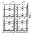
次に、前記特願平11−172624号に記載された太陽電池モジュールの設置方法の一例について説明する。図15,16は太陽電池モジュールの設置方法に関する例を示すもので、図15は太陽電池アレイの上面図、図16は図15のC−C部分断面図である。
【0018】
図15に於いて、太陽電池アレイ200は図示しない屋根面に太陽電池モジュール120を複数個、平面状に設置して構成している。
【0019】
図16においては、屋根の野地板3の表面にルーフィング材4が敷かれ、その断面形状が略I字状のアルミニュームなどの金属製、若しくはエポキシ樹脂などの構造用有機材料で構成された固定部材201が木ネジ6などで野地板3に固定されている。
【0020】
太陽電池モジュール120は、第4の保護層104を光入射側に、第8の保護層108を光入射側と反対側にして、第8の保護層108の非発電領域を、例えばブチルゴムなどで構成された緩衝材202を介して固定部材201の上リム203の上面に当接し、隣接する太陽電池モジュール120の側方の端部204の間に隙間205を開けて置かれている。
【0021】
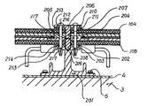
一方、断面形状が略T字状のアルミニュームなどの金属製、若しくはエポキシ樹脂などの構造用有機材料で構成された押え具206は、その略中央の突起部207が前記の隙間205に挿入され、且つ先端部208が固定部材201のほぼ中央部に設けられた溝209に嵌め込まれている。
【0022】
他方、突起部207から左右に延びた平板部210は、ブチルゴムなどの弾力性を有する有機材料で構成した当て板211を介して隣接する太陽電池モジュール120の非発電領域に当接し、押え具206の平板部210に開けられた穴212、当て板211に開けられた穴213、太陽電池モジュール120の取付け穴117、緩衝材202に開けられた穴214、固定部材201に開けられた穴215を連通して差し込みピン216で押え具206、当て板211、太陽電池モジュール120、緩衝材202、固定部材201を一体的に固定している。また、差し込みピン216は、その先端217が他のピン直径より大きく鏃(ヤシ゛リ)状になっており、かつ中央部にスリットが設けられ、差し込んだ後、抜けない構造となっている。
【0023】
図9は、前記図13ないし図16により説明した太陽電池モジュールとその設置方法に関わり、後の説明の便宜上、構成を簡略化して模式的に示したものである。
【0024】
図9に示す太陽電池モジュールにおいては、太陽電池51から電力を取出すための導電性粘着テープ52が太陽電池の陽極側、陰極側に電気的に接続され、太陽電池51の両側には太陽電池モジュールから太陽電池の電力を取出すための帯状の平箔金属板53が平行に配設され、この平箔金属板53と導電性粘着テープ52とが電気的に接続されている。太陽電池51、導電性粘着テープ52および平箔金属板53を表裏より、充填材として例えばEVAなどの熱溶着性プラスチック材54a、54bで保護し、またその表面に耐候性フィルムとしてETFEなどのフッ素系フィルム材を用いた表面保護材55a、55bを設けて一体化し、太陽電池モジュールを構成している。さらに、太陽電池の受光面と反対側の裏面には金属板56を配し、EVAなどの熱溶着性プラスチック材54cを用いてプラスチックフィルムのみで構成した太陽電池モジュールと金属板とを一体化している。
【0025】
この太陽電池モジュールの架台等への取付け設置方法は、図9に示すように、太陽電池モジュール設置台としての架台61に太陽電池モジュールを配置し、説明の便宜上、矢印で示す複数本のネジ62を太陽電池モジュールの非発電領域に貫通させ、架台61に固定するようにしている。
【0026】
【発明が解決しようとする課題】
ところで、前述のように、非発電領域に取付け穴を設けて、架台に直接ネジにより締め付け固定する従来の太陽電池モジュールの設置方法においては、設置が容易でかつコストが低減できるメリットはあるものの、以下のような問題点があった。
【0027】
図15および16に示すように、太陽電池モジュールの非発電領域にネジ等を貫通させて直接固定する場合、モジュールの温度が上昇した際、熱膨張量が吸収しきれずに、特に大型のモジュールの場合、モジュール全体に波打ちが発生するという不具合が生ずる。特に、モジュール底面に補強層として金属板を備える場合に顕著である。
【0028】
この発明は、上記のような問題点を解消するためになされたもので、本発明の課題は、軽量およびフレキシブル性を維持しつつモジュール強度も維持した太陽電池モジュールの設置方法であって、モジュールの熱膨張に伴う応力発生の軽減を図った簡便な太陽電池モジュールの設置方法を提供することにある。
【0029】
【課題を解決するための手段】
前述の課題を解決するため、この発明は、電気絶縁性を有するフィルム基板上に形成された太陽電池を、電気絶縁性の保護材により封止するために、太陽電池の受光面側および非受光面側の双方に保護層を設け、太陽電池の側方に前記保護層を延長して非発電領域を形成し、この非発電領域に、太陽電池モジュール設置用の取付け穴を設けた太陽電池モジュールを、設置用架台にネジにより締め付け固定する太陽電池モジュールの設置方法であって、前記取付け穴に、同心の中空部を有する円筒部材を嵌合し、かつ、同心のネジ貫通孔を有し、その外径が前記円筒部材の中空部内径より小さい円筒状の胴体部と、この胴体部の一側に設けられ、その外径が、前記モジュール設置用の取付け穴の直径より大きいフランジとを備えたフランジ付き円筒コマの胴体部を、前記円筒部材の中空部に挿入し、さらに、前記ネジ貫通孔にネジを挿入して、太陽電池モジュールを前記フランジを介してネジにより、設置用架台に締め付け固定し、かつ前記フランジ付き円筒コマの胴体部を、円筒部材の中空部に挿入した際に生ずる隙間寸法を、太陽電池モジュールの熱膨張による伸び量と同等以上とする(請求項1の発明)。
【0030】
また、請求項1に記載の設置方法において、前記同心の中空部を有する円筒部材に代えて、同心のレーストラック状の中空長穴部を有する円筒部材とし、この中空長穴部のレーストラックの直線部の長さ寸法を、太陽電池モジュールの熱膨張による伸び量と同等以上とし、レーストラックの幅寸法を、前記フランジ付き円筒コマの胴体部の外形寸法と略同一とする(請求項2の発明)。
【0031】
上記請求項1の発明によれば、円筒部材の中空部とフランジ付き円筒コマの胴体部との間に隙間があるので、モジュールに熱膨張による伸びが発生してもこの隙間分動くことができるため、モジュールに波打ちや撓みが発生することを防止することができる。また、請求項2の発明によれば、モジュールの熱膨張による伸びは、中空長穴部のレーストラックの直線部において吸収することができる。
【0032】
さらに、請求項3の発明によっても、この発明の課題は解決できる。即ち、請求項1に記載の設置方法において、前記同心の中空部を有する円筒部材に代えて、前記円筒部材の中空部内径を前記円筒コマの胴体部の外形寸法と略同一とし、かつ円筒部材の材質を、圧縮変形可能な弾性部材とする。上記において、円筒部材の材質を例えば、ゴム材とすることにより、太陽電池モジュールの熱膨張をこのゴム材が吸収し、モジュールに波打ちや撓みが発生することがない。
【0033】
また、ネジの頭が突出しないようにするためには、請求項4の発明が好ましい。即ち、請求項1ないし3のいずれか1項に記載の設置方法において、前記フランジ付き円筒コマのネジ貫通孔は、そのフランジ側に、テーパ穴部を備えることとする。
【0034】
さらにまた、太陽電池モジュールを傾斜面に取り付ける場合には、請求項5の発明が好適である。即ち、電気絶縁性を有するフィルム基板上に形成された太陽電池を、電気絶縁性の保護材により封止するために、太陽電池の受光面側および非受光面側の双方に保護層を設け、太陽電池の側方に前記保護層を延長して非発電領域を形成し、この非発電領域に、太陽電池モジュール設置用の取付け穴を設けた太陽電池モジュールを、設置用架台にネジにより締め付け固定する太陽電池モジュールの傾斜面への設置方法であって、傾斜面上流側最上位の複数の前記取付け穴には、請求項2に記載の同心のレーストラック状の中空長穴部を有する円筒部材を、中空長穴部の長手方向が前記傾斜面の傾斜方向と直交する方向となるように嵌合し、前記最上位より下位の複数の前記取付け穴には、請求項3に記載の弾性部材からなる同心の中空部を有する円筒部材を嵌合し、かつ、同心のネジ貫通孔を有し、その外径が前記円筒部材の中空長穴部のレーストラックの幅寸法あるいは前記中空部内径と略同一寸法の円筒状の胴体部と、この胴体部の一側に設けられ、その外径が、前記モジュール設置用の取付け穴の直径より大きいフランジとを備えたフランジ付き円筒コマの胴体部を、前記円筒部材の中空長穴部および中空部に挿入し、さらに、前記ネジ貫通孔にネジを挿入して、太陽電池モジュールを前記フランジを介してネジにより、設置用架台に締め付け固定し、かつ前記フランジ付き円筒コマの胴体部を、円筒部材の中空長穴部および中空部に挿入した際に生ずる隙間寸法を、太陽電池モジュールの熱膨張による伸び量と同等以上とする。
【0035】
傾斜面に設置する場合には、モジュールの自重が取付け穴部にかかるために、位置決めがしにくいことや、初期ずれによる伸び吸収効果の低減などの問題があるが、上記設置方法によれば後に詳述するように、最上位の取付け穴部で位置決めを行い、他の取付け穴部で伸び吸収が可能となるので、傾斜面への設置が容易でかつ、所期の目的が達成できる。
【0036】
【発明の実施の形態】
図面に基づき、この発明の実施例について以下に述べる。
【0037】
図1は、請求項1の発明に関わる円筒部材とフランジ付き円筒コマの斜視図を示し、図4は、太陽電池モジュールの設置上面図を示し、図5は、図4におけるA−A断面図を示す。図1(a)に示す円筒部材31は、同心の中空部311を有し、円筒部材の外形寸法は、太陽電池モジュールの取付け穴と略同一とし、緩く嵌合するような寸法としている。円筒部材の長さは、太陽電池モジュールの厚さと略同一とする。
【0038】
図1(b)に示すフランジ付き円筒コマ32は、太陽電池モジュール120に設けた取付け穴70の直径寸法よりも大きいフランジ321と、直径が円筒部材31に設けた中空部311の直径よりも小さい胴体部322から構成され、また、モジュールを固定するためのネジ貫通孔323を有している。なお、前記円筒部材およびフランジ付き円筒コマの材料としては、ステンレススチール(SUS),アルミニウム等の金属材料やポリアミドなどの等硬質プラスチック材料等が適用できる。
【0039】
図4、図5において、太陽電池モジュール120の構造は、前述の図9に示す構造と同一構造である。太陽電池モジュール120は、太陽電池モジュール設置架台61に載置され、取付け穴70に円筒部材31を嵌合し、太陽電池受光面側からフランジ付き円筒コマ32の胴体部322を、円筒部材31に設けた中空部311に挿入し、フランジ付き円筒コマ32のネジ貫通孔323にネジ62を通し、架台61にネジで締め付け、太陽電池モジュール120を固定する。
【0040】
図5において、円筒部材31に設けた中空部311の直径m2とフランジ付き円筒コマ32の胴体部322の直径m1の差によって生ずる隙間Δmは、太陽電池モジュール120の熱膨張長さと同じまたはそれ以上となるようにm1、m2を定める。なお、図5において、太陽電池モジュールの固定と熱膨張への追随性の観点から、太陽電池モジュール120とフランジ321との間には、弾性部材からなる図示しないワッシャを挿入するのが好ましい。
【0041】
図2は、請求項2に関わる中空長穴部を有する円筒部材とフランジ付き円筒コマの斜視図である。図2(a)に示す円筒部材31aは、同心のレーストラック状の中空長穴部312を有するものとし、この中空長穴部312のレーストラックの直線部の長さ寸法n1を、太陽電池モジュールの熱膨張による伸び量と同等以上とし、レーストラックの幅寸法n2を、図2(b)に示すフランジ付き円筒コマ32の胴体部322の外形寸法と略同一とする。図2(b)に示すフランジ付き円筒コマ32は、図1(b)に示すものと、結果的に寸法上も同一でありうる。前記中空長穴部を有する円筒部材31aおよびフランジ付き円筒コマ部材32を用いた太陽電池モジュールの設置方法は、図5によって説明した方法と同様である。
【0042】
図6は、請求項3に関わる弾性部材からなる円筒部材を使って太陽電池モジュールを固定した時の固定部分の部分断面図である。図6において、円筒部材51は、例えば、クロロプレンゴム,ポリエチレンスポンジ,シリコンゴム等の弾性部材からなり、その肉厚aは、太陽電池モジュール120が熱膨張によって起きる長さ以上の寸法としている。また、円筒部材51に設けた中空部511の寸法は、フランジ付き円筒コマの胴体部322の寸法と略同一あるいはそれ以下とする。円筒部材51を、フランジ付き円筒コマの胴体部322に挿入して、太陽電池モジュール120に設けた取付け穴70に嵌合し、前述と同様にして太陽電池モジュールを固定する。
【0043】
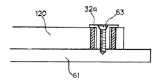
図3は、請求項4に関わるフランジ付き円筒コマ32aの断面図を示す。また、図7に、本フランジ付き円筒コマ32aを用いて太陽電池モジュール120を固定した時の断面図を示す。図3において、フランジ付き円筒コマ32aのネジ貫通孔323は、そのフランジ側に、テーパ穴部324を備える。これにより、図7に示すように、皿ネジ63で太陽電池モジュール120を固定した場合、ネジ頭部が隠れるので、意匠性を向上させることができる。
【0044】
図8は、請求項5の発明に関わる太陽電池モジュールの設置図を示す。図中、紙面上側が傾斜面の上流側である。この上流側の最上位のモジュール取付け穴70には、中空長穴部を有する円筒部材31aを長寸法がケラバ方向に平行となるように嵌合する。また、その他のモジュールの取付け穴には、材料がゴム材の円筒部材51を嵌合し、各円筒部材に受光面側からフランジ付き円筒コマ32または32aを挿入し、フランジ付き円筒コマにネジ62を通し太陽電池モジュール設置架台61に固定する。
【0045】
上記のモジュール設置法は、設置傾斜角度が大きい場合に特に適している。設置角度が急勾配な架台にモジュールを取付ける場合、請求項1の発明の方法ではフランジ付き円筒コマを円筒部材中空部の中心位置に合わせることが困難である。また、請求項3の発明の方法では、ゴム材がモジュールの重さで縮むため、フランジ付き円筒コマをモジュール取付け穴中心でネジ止めすることが出来なくなる。一方、請求項2の発明に関わる円筒部材は、レーストラックの幅寸法をフランジ付き円筒コマ胴体部の寸法と略同じにしているため、レーストラックの幅方向に対してフランジ付き円筒コマの位置を決めることができる。したがって、急勾配な架台にモジュールを固定する時、図8のように、傾斜面流れ方向、例えば屋根流れ方向の上流側最上位のモジュール取付け穴に請求項2に関わる円筒部材31aを使ってモジュール固定位置の位置決めを行い、その他は請求項3の発明に関わる弾性部材からなる円筒部材を使うことにより取付け穴部においてモジュールの伸びの吸収が可能となるので、傾斜面への設置が容易でかつ、所期の目的が達成できる。
【0046】
【発明の効果】
上記のとおり、この発明によれば、電気絶縁性を有するフィルム基板上に形成された太陽電池を、電気絶縁性の保護材により封止するために、太陽電池の受光面側および非受光面側の双方に保護層を設け、太陽電池の側方に前記保護層を延長して非発電領域を形成し、この非発電領域に、太陽電池モジュール設置用の取付け穴を設けた太陽電池モジュールを、設置用架台にネジにより締め付け固定する太陽電池モジュールの設置方法であって、前記取付け穴に、同心の中空部を有する円筒部材を嵌合し、かつ、同心のネジ貫通孔を有し、その外径が前記円筒部材の中空部内径より小さい円筒状の胴体部と、この胴体部の一側に設けられ、その外径が、前記モジュール設置用の取付け穴の直径より大きいフランジとを備えたフランジ付き円筒コマの胴体部を、前記円筒部材の中空部に挿入し、さらに、前記ネジ貫通孔にネジを挿入して、太陽電池モジュールを前記フランジを介してネジにより、設置用架台に締め付け固定することとし、 上記において、フランジ付き円筒コマの胴体部を、円筒部材の中空部に挿入した際に生ずる隙間寸法を、太陽電池モジュールの熱膨張による伸び量と同等以上とするか、または、前記同心の中空部を有する円筒部材に代えて、同心のレーストラック状の中空長穴部を有する円筒部材とし、この中空長穴部のレーストラックの直線部の長さ寸法を、太陽電池モジュールの熱膨張による伸び量と同等以上とし、レーストラックの幅寸法を、前記フランジ付き円筒コマの胴体部の外形寸法と略同一とするか、さらには、前記同心の中空部を有する円筒部材に代えて、前記円筒部材の中空部内径を前記円筒コマの胴体部の外形寸法と略同一とし、かつ円筒部材の材質を、圧縮変形可能な弾性部材とすることにより、モジュールの熱膨張による伸びを、円筒部材の中空部とフランジ付き円筒コマの胴体部との間の隙間、または中空長穴部のレーストラックの直線部、さらには弾性部材からなる円筒部材で吸収して、モジュールに波打ちや撓みが発生することを防止することができる。
【図面の簡単な説明】
【図1】 この発明の実施例に関わるフランジ付き円筒コマと円筒部材の斜視図
【図2】 図1とは異なるフランジ付き円筒コマと円筒部材の斜視図
【図3】 図1とはさらに異なるフランジ付き円筒コマの斜視図
【図4】 この発明の請求項1の発明に関わる太陽電池モジュールの設置状態の上面図
【図5】 図4のA−A拡大部分断面図
【図6】 太陽電池モジュールの図5とは異なる設置状態の拡大部分断面図
【図7】 太陽電池モジュールの図5とはさらに異なる設置状態の拡大部分断面図
【図8】 この発明の請求項5の発明に関わる太陽電池モジュールの設置状態の上面図
【図9】 従来の太陽電池モジュールの設置例を示す模式図
【図10】 従来の太陽電池モジュールの異なる設置方法を示す斜視図
【図11】 従来の太陽電池モジュールのさらに異なる設置方法を示す上面図
【図12】 図11の太陽電池モジュールの設置構造を示す断面図
【図13】 従来の太陽電池モジュールの上面図
【図14】 図13の太陽電池モジュールの断面図
【図15】 図13の太陽電池モジュールの設置方法の一例を示す上面図
【図16】 図15の太陽電池モジュールの設置構造を示す断面図
【符号の説明】
31,31a,51:円筒部材、32,32a:フランジ付き円筒コマ、61:架台、62:ネジ、70:取付け穴、120:太陽電池モジュール、311,511:中空部、312:中空長穴部、321:フランジ、322:胴体部、323:ネジ貫通孔、324:テーパ穴部。[0001]
BACKGROUND OF THE INVENTION
In order to seal a solar cell formed on an electrically insulating film substrate with an electrically insulating protective material, a protective layer is provided on both the light-receiving surface side and the non-light-receiving surface side of the solar cell. It is related with the installation method of the provided solar cell module.
[0002]
[Prior art]
Currently, clean energy research and development is underway from the standpoint of environmental protection. Among them, solar cells are attracting attention because their resources (sunlight) are infinite and pollution-free. A typical example of a solar cell (photoelectric conversion device) in which a plurality of solar cell elements formed on the same substrate are connected in series is a thin film solar cell.
[0003]
Thin-film solar cells are expected to become the mainstream of solar cells in the future because they are thin and lightweight, inexpensive to manufacture, and easy to increase in area, and are attached to roofs and windows of buildings in addition to power supply. Demand is also expanding for commercial and general residential use.
[0004]
Conventional thin-film solar cells have used glass substrates, but research and development of flexible solar cells using plastic films has been promoted in terms of weight reduction, workability, and mass productivity. Utilizing this flexibility, mass production became possible by the roll-to-roll manufacturing method.
[0005]
As the above thin film solar cell module, in order to seal the solar cell formed on the electrically insulating film substrate with an electrically insulating protective material, the light receiving surface side and the non-light receiving surface side of the solar cell What provided the protective layer in both is known.
[0006]
Since the protective material of the solar cell module is plastic, the strength against twisting and pulling force is weak, and there is a risk that the solar cell module may be damaged by external force during construction. Therefore, as described in Japanese Patent No. 2651121 and Japanese Patent No. 2719114, a reinforcing plate is provided on the entire back surface of the solar cell module, or it is reinforced in a non-power generation region as described in Japanese Utility Model Publication No. 55-25383. A structure that uses both a material and a power lead has been developed.
[0007]
Further, as a method for installing the solar cell module on the roof or the like, the following methods are known. As a method for installing a solar cell module sealed with a resin protective material, for example, a method described in Japanese Patent No. 2651121 is known. FIG. 10 shows a schematic configuration thereof. In FIG. 10,
[0008]
On the other hand, the following method is known as a method for installing the glass cover type solar cell module. FIG. 11 is a partial plan view of the solar cell array, and FIG. 12 is a cross-sectional view taken along the line DD of FIG. The
[0009]
By the way, in the case of the solar cell module described in the Japanese Utility Model Laid-Open No. 55-25383, there is a problem that the flexibility is not increased and the weight is increased. In the case of the solar cell module described in Japanese Patent No. 2651121, the entire surface is reinforced. The module weight is increased, and the reinforcing plate, filler and translucent film are folded to the opposite side of the light receiving surface in relation to the module installation method, resulting in poor workability and high processing costs. The cost increases as a whole, such as requiring large bending equipment. Further, when the size of the solar cell module is reduced, the number of attachments increases when a certain size solar cell array is constructed, and the number of work steps increases. Moreover, a terminal and a cable are needed for every solar cell module, and the cost of a solar cell module increases also from this viewpoint.
[0010]
On the other hand, the method for installing the glass cover solar cell module has the following problems. Since glass is used, the solar cell module is heavy, and since glass cannot be directly fixed to the mounting base by screws or the like, a support frame (frame) for supporting the glass is required. Since the support frame supports heavy glass, the support frame becomes a strong frame. As a result, the solar cell module becomes heavier and the cost of the support frame is added, resulting in an increase in cost.
[0011]
The applicant of the present invention has developed a solar cell module that eliminates the above-mentioned problems, maintains light weight and flexibility, maintains module strength, is easy to install, and reduces costs, and its installation method. This is proposed in Japanese Patent Application No. 11-172624. FIGS. 13 to 16 show an example of the solar cell module described in Japanese Patent Application No. 11-172624 and an installation method thereof.
[0012]
FIG. 13 is a top view of the solar cell module, and FIG. 14 is a cross-sectional view taken along line AA of FIG. As shown in FIGS. 13 and 14, in order to seal the
[0013]
13 and 14, the first
[0014]
Here, the first
[0015]
On the other hand, on both sides of the
[0016]
On the other hand, the first
[0017]
Next, an example of a method for installing the solar cell module described in Japanese Patent Application No. 11-172624 will be described. FIGS. 15 and 16 show an example of a solar cell module installation method. FIG. 15 is a top view of the solar cell array, and FIG. 16 is a partial cross-sectional view taken along the line CC in FIG.
[0018]
In FIG. 15, a
[0019]
In FIG. 16, a
[0020]
The
[0021]
On the other hand, the presser 206 made of a metal such as aluminum having a substantially T-shaped cross section or a structural organic material such as an epoxy resin has a substantially
[0022]
On the other hand, the
[0023]
FIG. 9 relates to the solar cell module described with reference to FIGS. 13 to 16 and the installation method thereof, and schematically shows the configuration in a simplified manner for convenience of later description.
[0024]
In the solar cell module shown in FIG. 9, a conductive
[0025]
As shown in FIG. 9, the solar cell module is mounted on a
[0026]
[Problems to be solved by the invention]
By the way, as described above, in the installation method of the conventional solar cell module in which the mounting hole is provided in the non-power generation region and directly fixed to the pedestal with the screw, there is an advantage that the installation is easy and the cost can be reduced. There were the following problems.
[0027]
As shown in FIGS. 15 and 16, when directly fixing screws or the like through the non-power generation region of the solar cell module, when the temperature of the module rises, the amount of thermal expansion cannot be absorbed, In such a case, there arises a problem that the entire module is wavy. This is particularly noticeable when a metal plate is provided as a reinforcing layer on the bottom surface of the module.
[0028]
The present invention has been made to solve the above problems, and an object of the present invention is to provide a solar cell module installation method that maintains module strength while maintaining light weight and flexibility. An object of the present invention is to provide a simple method for installing a solar cell module that reduces the generation of stress associated with thermal expansion of the solar cell.
[0029]
[Means for Solving the Problems]
In order to solve the above-described problems, the present invention provides a solar cell on the light-receiving surface side and a non-light-receiving side for sealing a solar cell formed on an electrically insulating film substrate with an electrically insulating protective material. A solar cell module in which a protective layer is provided on both sides and the non-power generation region is formed by extending the protective layer on the side of the solar cell, and a mounting hole for installing the solar cell module is provided in the non-power generation region. Is a method of installing a solar cell module that is fastened and fixed to a mounting base with a screw, wherein the mounting hole is fitted with a cylindrical member having a concentric hollow portion, and has a concentric screw through hole, A cylindrical body part whose outer diameter is smaller than the inner diameter of the hollow part of the cylindrical member, and a flange which is provided on one side of the body part and whose outer diameter is larger than the diameter of the mounting hole for installing the module. With flange The body portion of the tubular frame, is inserted into the hollow portion of the cylindrical member, further, by inserting screws into the screw holes, the screw solar cell module via the flange, fastened to the installation for frame And the gap size generated when the body portion of the flanged cylindrical piece is inserted into the hollow portion of the cylindrical member is equal to or greater than the elongation due to thermal expansion of the solar cell module. (Invention of Claim 1)
[0030]
Further, in the installation method according to
[0031]
Claims above 1's According to the invention, since there is a gap between the hollow part of the cylindrical member and the body part of the flanged cylindrical piece, even if the module is stretched due to thermal expansion, it can move by this gap. Or bending can be prevented.
[0032]
And claims 3 The present invention can also solve the problems of the present invention. That is, in the installation method according to
[0033]
In order to prevent the head of the screw from protruding, 4 The invention is preferred. That is, claims 1 to 3 Either 1 item In the installation method described above, the screw through hole of the flanged cylindrical piece is provided with a tapered hole portion on the flange side.
[0034]
Furthermore, when attaching the solar cell module to the inclined surface, the
[0035]
When installing on an inclined surface, the module's own weight is applied to the mounting hole, so there are problems such as difficulty in positioning and reduction of the elongation absorption effect due to initial deviation. As will be described in detail, positioning is performed at the uppermost mounting hole, and elongation can be absorbed by other mounting holes, so that installation on an inclined surface is easy and the intended purpose can be achieved.
[0036]
DETAILED DESCRIPTION OF THE INVENTION
An embodiment of the present invention will be described below with reference to the drawings.
[0037]
FIG. 1
[0038]
The flanged
[0039]
4 and 5, the
[0040]
In FIG. 5, the gap Δm generated by the difference between the diameter m2 of the
[0041]
2
[0042]
FIG. 6 claims 3 It is a fragmentary sectional view of the fixing | fixed part when fixing a solar cell module using the cylindrical member which consists of an elastic member in connection with. In FIG. 6, the
[0043]
3
[0044]
FIG. 8
[0045]
The above module installation method is particularly suitable when the installation inclination angle is large. If the module is mounted on a mounting base with a
[0046]
【The invention's effect】
As described above, according to the present invention, in order to seal the solar cell formed on the electrically insulating film substrate with the electrically insulating protective material, the light receiving surface side and the non-light receiving surface side of the solar cell. A protective layer is provided on both sides, the protective layer is extended to the side of the solar cell to form a non-power generation region, and in this non-power generation region, a solar cell module provided with a mounting hole for solar cell module installation, A method of installing a solar cell module that is fastened and fixed to a mounting base with screws, wherein a cylindrical member having a concentric hollow portion is fitted into the mounting hole, and a concentric screw through hole is provided, A flange having a cylindrical body portion whose diameter is smaller than the inside diameter of the hollow portion of the cylindrical member, and a flange which is provided on one side of the body portion and whose outer diameter is larger than the diameter of the mounting hole for installing the module Cylindrical core with The body portion of the cylindrical member is inserted into the hollow portion of the cylindrical member, and further, a screw is inserted into the screw through hole, and the solar cell module is fastened and fixed to the installation base with the screw through the flange, In the above, the gap size generated when the body portion of the flanged cylindrical piece is inserted into the hollow portion of the cylindrical member is equal to or larger than the elongation amount due to thermal expansion of the solar cell module, or the concentric hollow portion Instead of the cylindrical member having a cylindrical member having a concentric racetrack-like hollow elongated hole portion, the length of the straight portion of the racetrack in the hollow elongated hole portion is determined by the amount of elongation due to thermal expansion of the solar cell module. A cylindrical member having a race track width dimension substantially equal to the outer dimension of the body part of the flanged cylindrical piece, or having the concentric hollow part. Instead, the inner diameter of the hollow part of the cylindrical member is substantially the same as the outer dimension of the body part of the cylindrical piece, and the cylindrical member is made of an elastic member that can be compressed and deformed, so that the expansion due to the thermal expansion of the module is increased. Absorbed by the gap between the hollow part of the cylindrical member and the body part of the flanged cylindrical piece, or by the straight part of the race track in the hollow long hole part, and also by the cylindrical member made of an elastic member, the module is wavy or bent. Can be prevented.
[Brief description of the drawings]
FIG. 1 is a perspective view of a cylindrical piece with a flange and a cylindrical member according to an embodiment of the present invention.
FIG. 2 is a perspective view of a cylindrical piece with a flange and a cylindrical member different from those in FIG.
FIG. 3 is a perspective view of a flanged cylindrical piece further different from FIG.
FIG. 4 is a top view of an installed state of a solar cell module according to the invention of
5 is an AA enlarged partial cross-sectional view of FIG.
6 is an enlarged partial cross-sectional view of a solar cell module installed in a state different from that shown in FIG.
FIG. 7 is an enlarged partial cross-sectional view of the solar cell module in a different installation state from FIG.
FIG. 8 Claims of the
FIG. 9 is a schematic view showing an installation example of a conventional solar cell module.
FIG. 10 is a perspective view showing a different installation method of a conventional solar cell module.
FIG. 11 is a top view showing yet another method of installing a conventional solar cell module.
12 is a cross-sectional view showing the installation structure of the solar cell module of FIG.
FIG. 13 is a top view of a conventional solar cell module.
14 is a cross-sectional view of the solar cell module of FIG.
15 is a top view showing an example of a method for installing the solar cell module of FIG.
16 is a sectional view showing the installation structure of the solar cell module of FIG.
[Explanation of symbols]
31, 31a, 51: Cylindrical member, 32, 32a: Flange cylindrical piece, 61: Mount, 62: Screw, 70: Mounting hole, 120: Solar cell module, 311, 511: Hollow part, 312: Hollow long hole part 321: flange, 322: body part, 323: screw through hole, 324: taper hole part.
Claims (5)
Priority Applications (1)
| Application Number | Priority Date | Filing Date | Title |
|---|---|---|---|
| JP2000194572A JP3932012B2 (en) | 2000-06-28 | 2000-06-28 | Installation method of solar cell module |
Applications Claiming Priority (1)
| Application Number | Priority Date | Filing Date | Title |
|---|---|---|---|
| JP2000194572A JP3932012B2 (en) | 2000-06-28 | 2000-06-28 | Installation method of solar cell module |
Publications (2)
| Publication Number | Publication Date |
|---|---|
| JP2002016277A JP2002016277A (en) | 2002-01-18 |
| JP3932012B2 true JP3932012B2 (en) | 2007-06-20 |
Family
ID=18693374
Family Applications (1)
| Application Number | Title | Priority Date | Filing Date |
|---|---|---|---|
| JP2000194572A Expired - Fee Related JP3932012B2 (en) | 2000-06-28 | 2000-06-28 | Installation method of solar cell module |
Country Status (1)
| Country | Link |
|---|---|
| JP (1) | JP3932012B2 (en) |
Families Citing this family (5)
| Publication number | Priority date | Publication date | Assignee | Title |
|---|---|---|---|---|
| KR101007622B1 (en) | 2009-06-30 | 2011-01-12 | 김종완 | The supporting device for signal lamp |
| CN101980378B (en) * | 2010-09-08 | 2014-12-24 | 常州亿晶光电科技有限公司 | Overtemperature alarm device for solar energy component framing machine |
| JP2012193553A (en) * | 2011-03-17 | 2012-10-11 | Fuji Electric Co Ltd | Device for fixing solar cell module |
| CN102832292B (en) * | 2012-09-13 | 2015-02-04 | 苏州晟成新能源科技有限公司 | servo drive pack frame machine |
| FR3033461B1 (en) * | 2015-03-02 | 2017-02-24 | Superdome Sarl | PHOTOVOLTAIC TILE |
-
2000
- 2000-06-28 JP JP2000194572A patent/JP3932012B2/en not_active Expired - Fee Related
Also Published As
| Publication number | Publication date |
|---|---|
| JP2002016277A (en) | 2002-01-18 |
Similar Documents
| Publication | Publication Date | Title |
|---|---|---|
| US6670541B2 (en) | Solar battery, solar generating apparatus, and building | |
| JP3792867B2 (en) | Solar cell module, solar cell array, and solar power generation apparatus construction method | |
| KR100325951B1 (en) | Solar cell module enclosure with solar cells, enclosure installation method, and solar cell system | |
| JP3674234B2 (en) | Large solar cell module | |
| US6128868A (en) | Combination solar battery and roof member, and mounting method thereof | |
| EP1104029B1 (en) | Solar battery unit | |
| KR100287089B1 (en) | Solar cell module and solar cell integrated cladding assembly | |
| US20010034982A1 (en) | Solar cell-bearing roof and method for installing solar cell-bearing roof | |
| US20120118355A1 (en) | Flexible solar shell and support structure for use with rooftops | |
| US20110073163A1 (en) | Photovoltaic lamination and roof mounting systems | |
| JP4556956B2 (en) | Installation method of solar cell module | |
| JP3932008B2 (en) | Solar cell module | |
| JP2006278672A (en) | Structure of accommodating power transmission cable, and solar battery module employing same | |
| JP3940944B2 (en) | Installation method of solar cell module | |
| JP3932012B2 (en) | Installation method of solar cell module | |
| US20180219509A1 (en) | Easy to install flexible photovoltaic modules | |
| JP4325107B2 (en) | Solar cell module installation method and solar cell curtain structure | |
| JP3952249B2 (en) | Installation method of solar cell module | |
| JPH11214734A (en) | Solar battery module, its manufacture and execution method and solar battery power generation system | |
| JP4379562B2 (en) | Power generation device having a plurality of solar cell modules | |
| JP2005175236A (en) | Solar cell module | |
| CN214739325U (en) | Flexible light photovoltaic waterproofing membrane and mounting structure thereof | |
| CN214753799U (en) | Junction box-free flexible light photovoltaic module | |
| CN218292382U (en) | Interlayer photovoltaic curtain wall and building | |
| JP4477765B2 (en) | Photovoltaic power generation unit array and manufacturing method thereof, solar power generation device, and roof device |
Legal Events
| Date | Code | Title | Description |
|---|---|---|---|
| A621 | Written request for application examination |
Free format text: JAPANESE INTERMEDIATE CODE: A621 Effective date: 20050323 |
|
| A977 | Report on retrieval |
Free format text: JAPANESE INTERMEDIATE CODE: A971007 Effective date: 20061110 |
|
| A131 | Notification of reasons for refusal |
Free format text: JAPANESE INTERMEDIATE CODE: A131 Effective date: 20061130 |
|
| A521 | Written amendment |
Free format text: JAPANESE INTERMEDIATE CODE: A523 Effective date: 20070124 |
|
| TRDD | Decision of grant or rejection written | ||
| A01 | Written decision to grant a patent or to grant a registration (utility model) |
Free format text: JAPANESE INTERMEDIATE CODE: A01 Effective date: 20070222 |
|
| A61 | First payment of annual fees (during grant procedure) |
Free format text: JAPANESE INTERMEDIATE CODE: A61 Effective date: 20070307 |
|
| R150 | Certificate of patent or registration of utility model |
Free format text: JAPANESE INTERMEDIATE CODE: R150 |
|
| FPAY | Renewal fee payment (event date is renewal date of database) |
Free format text: PAYMENT UNTIL: 20100323 Year of fee payment: 3 |
|
| S111 | Request for change of ownership or part of ownership |
Free format text: JAPANESE INTERMEDIATE CODE: R313113 |
|
| FPAY | Renewal fee payment (event date is renewal date of database) |
Free format text: PAYMENT UNTIL: 20100323 Year of fee payment: 3 |
|
| R350 | Written notification of registration of transfer |
Free format text: JAPANESE INTERMEDIATE CODE: R350 |
|
| FPAY | Renewal fee payment (event date is renewal date of database) |
Free format text: PAYMENT UNTIL: 20110323 Year of fee payment: 4 |
|
| FPAY | Renewal fee payment (event date is renewal date of database) |
Free format text: PAYMENT UNTIL: 20110323 Year of fee payment: 4 |
|
| FPAY | Renewal fee payment (event date is renewal date of database) |
Free format text: PAYMENT UNTIL: 20120323 Year of fee payment: 5 |
|
| FPAY | Renewal fee payment (event date is renewal date of database) |
Free format text: PAYMENT UNTIL: 20120323 Year of fee payment: 5 |
|
| S111 | Request for change of ownership or part of ownership |
Free format text: JAPANESE INTERMEDIATE CODE: R313111 |
|
| FPAY | Renewal fee payment (event date is renewal date of database) |
Free format text: PAYMENT UNTIL: 20120323 Year of fee payment: 5 |
|
| R350 | Written notification of registration of transfer |
Free format text: JAPANESE INTERMEDIATE CODE: R350 |
|
| FPAY | Renewal fee payment (event date is renewal date of database) |
Free format text: PAYMENT UNTIL: 20120323 Year of fee payment: 5 |
|
| FPAY | Renewal fee payment (event date is renewal date of database) |
Free format text: PAYMENT UNTIL: 20130323 Year of fee payment: 6 |
|
| FPAY | Renewal fee payment (event date is renewal date of database) |
Free format text: PAYMENT UNTIL: 20130323 Year of fee payment: 6 |
|
| FPAY | Renewal fee payment (event date is renewal date of database) |
Free format text: PAYMENT UNTIL: 20140323 Year of fee payment: 7 |
|
| R250 | Receipt of annual fees |
Free format text: JAPANESE INTERMEDIATE CODE: R250 |
|
| LAPS | Cancellation because of no payment of annual fees |