JP3929635B2 - Exposure method - Google Patents
Exposure method Download PDFInfo
- Publication number
- JP3929635B2 JP3929635B2 JP06070899A JP6070899A JP3929635B2 JP 3929635 B2 JP3929635 B2 JP 3929635B2 JP 06070899 A JP06070899 A JP 06070899A JP 6070899 A JP6070899 A JP 6070899A JP 3929635 B2 JP3929635 B2 JP 3929635B2
- Authority
- JP
- Japan
- Prior art keywords
- magnification
- linear error
- error
- reticle
- linear
- Prior art date
- Legal status (The legal status is an assumption and is not a legal conclusion. Google has not performed a legal analysis and makes no representation as to the accuracy of the status listed.)
- Expired - Fee Related
Links
- 238000000034 method Methods 0.000 title claims description 42
- 239000000758 substrate Substances 0.000 claims description 66
- 238000012937 correction Methods 0.000 claims description 41
- 238000010586 diagram Methods 0.000 description 7
- 230000003287 optical effect Effects 0.000 description 4
- 239000002131 composite material Substances 0.000 description 1
- 238000009795 derivation Methods 0.000 description 1
- 230000000694 effects Effects 0.000 description 1
- 238000005259 measurement Methods 0.000 description 1
Images


Classifications
-
- G—PHYSICS
- G03—PHOTOGRAPHY; CINEMATOGRAPHY; ANALOGOUS TECHNIQUES USING WAVES OTHER THAN OPTICAL WAVES; ELECTROGRAPHY; HOLOGRAPHY
- G03F—PHOTOMECHANICAL PRODUCTION OF TEXTURED OR PATTERNED SURFACES, e.g. FOR PRINTING, FOR PROCESSING OF SEMICONDUCTOR DEVICES; MATERIALS THEREFOR; ORIGINALS THEREFOR; APPARATUS SPECIALLY ADAPTED THEREFOR
- G03F9/00—Registration or positioning of originals, masks, frames, photographic sheets or textured or patterned surfaces, e.g. automatically
- G03F9/70—Registration or positioning of originals, masks, frames, photographic sheets or textured or patterned surfaces, e.g. automatically for microlithography
- G03F9/7003—Alignment type or strategy, e.g. leveling, global alignment
Landscapes
- Physics & Mathematics (AREA)
- General Physics & Mathematics (AREA)
- Exposure And Positioning Against Photoresist Photosensitive Materials (AREA)
- Exposure Of Semiconductors, Excluding Electron Or Ion Beam Exposure (AREA)
Description
【0001】
【発明の属する技術分野】
本発明は、露光装置を用いてパターンを基板に転写する工程で、特に基板上のパターンの位置精度に高精度が要求される場合の露光方法に関する。
【0002】
【従来の技術】
従来、露光装置を用いてパターンの転写を行う際、特に何も露光されていないブランクの基板に転写を行う場合、転写に使用するレチクルの倍率、直交度誤差、露光装置の光学系による倍率,直交度誤差、そして露光装置のステージの倍率,直交度誤差などの線型誤差は考慮されることはなかった。
【0003】
例えば1枚の被転写基板に1枚のレチクルを用いて複数のショットを境界同士が接するように露光を行う場合、線型誤差を含まない理想的な条件下においては図10に示すようにショット同士の境界が接し、ショット内の十字で示したパターンも直交座標系に載っている。
【0004】
しかし、実際の露光では転写されたパターンの位置誤差は前記誤差を全て含むため非常に大きいものになる。また、被転写基板上での位置誤差は前記複数の線型誤差の組み合わせとなるため、線型誤差ではなく非線型の誤差になってしまう。 図11は模式的にこれらの位置誤差を示したものである。理想的にはショットの境界同士が接するはずが、ショットとステージの基準となる長さが異なるため、境界が分離してしまう。また理想的には点線の交点にあるべき十字のパターンは所定の位置からずれてしまっている。
【0005】
【発明が解決しようとする課題】
上記した位置誤差が許容されていたのは、今までは基板上で他の層との重ねあわせ精度を管理すればよく、位置誤差で問題になるのは、露光装置によって転写されるショット内のみであったことによる。ところが基板上でのパターンの位置精度自体が要求されるような局面、例えば基板上で他の層との重ね合わせ露光の精度を更に向上させたい場合、この転写基板をレチクルとして使用する場合、複数のレチクルを合わせることで目的のパターンとする場合等においては、上記のような露光方法では要求される位置精度を達成することができないという問題が生じる。
【0006】
本発明は、上述の如き従来の課題を解決するためになされたもので、その目的は、基板上でのパターンの位置を高精度に露光することができる露光方法を提供することである。
【0007】
【課題を解決するための手段】
上記目的を達成するために、本発明の特徴は、原版を複数回露光することで被転写基板上に複数個のショットによるパターンを形成する露光方法において、前記被転写基板上における各ショット内のパターン位置の倍率及び直交度などの線型誤差とショット毎の位置の倍率及び直交度などの線型誤差が各成分で等しくなるように、前記被転写基板を載せるステージの移動距離と方向を補正することにある。
【0010】
本発明の他の特徴は、露光装置のステージ上に設置された基板を少なくとも1つのマスクを用いて複数回露光することで前記基板上に複数個のパターンを形成する露光方法において、前記マスクによって形成されたパターンの第1の位置線型誤差および前記露光装置がパターン転写時に生ぜしめる第2の位置線型誤差および前記露光装置のステージが有する第3の位置線型誤差を求めるステップと前記第1、第2および第3の位置線型誤差が相互に等しくなるように前記露光装置の調整要素を調整する、あるいは前記ステージの移動を調整するステップとを有することである。
【0011】
本発明の他の特徴は、線型誤差の各成分を独立に補正可能で複数枚の原版を複数回露光することで被転写基板上に複数個のショットによるパターンを形成する露光方法において、各ショット内のパターン位置の倍率及び直交度などの線型誤差とショット毎の位置の倍率及び直交度などの線型誤差が各成分で等しくなるように使用する原版毎に露光条件を補正することにある。
【0012】
【発明の実施の形態】
以下、本発明の実施の形態を図面に基づいて説明する。まず、本発明の露光方法の第1の実施の形態を説明する。
【0013】
本例は、露光装置の光学系による一部の線型誤差を補正する機構を有する Nikon社製NSR-2005i11Dを使用し、被転写基板においては誤差の内で線型誤差は許される場合について述べる。
【0014】
NSR-2005i11Dにおいて補正可能な線型誤差は光学的な倍率補正であり、X方向,Y方向を独立に補正することはできない。また、被転写基板において線型誤差が許される理由は、例えばこの基板を Nikon社製 NSR-S201Aにおいて使用するレチクルとする場合、全ての線型誤差が補正可能であるため、被転写基板上での線型誤差は問題とならないことによる。
【0015】
露光に使用するレチクルが1枚で、それぞれのショットの境界が重なるような場合の事例を以下で述べる。使用したレチクルによる被転写基板上で測定したショット内パターン位置の線型誤差は以下のような数値であった。
【0016】
倍率誤差においてX方向が−1.2[ppm]、Y方向が−0.8[ppm]、直交度誤差が−1.1[μrad]であった。これらの数値は露光装置のステージに何も補正を加えなかった場合で、露光装置のステージを基準とした相対的な誤差である。
【0017】
数値の導出にあたってはレチクルを被転写基板である8inchウェハに露光した後現像を行ってパターンを形成し、 Leica社製LMS IPROを用いて被転写基板を測定した。
【0018】
レチクルを従来のようにステージの精度のみで露光した結果を模式的に示したのが図1である。線型誤差の内で回転の成分を除去するために転写されたパターンと露光装置のステージとで、X方向の合わせはとられている。この時の線型成分を除いたパターン位置の残留誤差は3σでX、Y方向でそれぞれ64,52nmであった。
【0019】
前記の通りX方向で−1.2[ppm],Y方向で−0.8[ppm]の倍率誤差があり、露光ショットの大きさに比較してステージの動きが大きいため、ショットの境界が離れてしまった。20mm角大のショットを露光したため、X,Y方向のショット境界のずれ量Δx,Δyはそれぞれ24,16nmであった。
【0020】
このずれ量を補正すべく、ステージの移動距離に倍率補正を加えて露光を行った結果が図1である。補正数値はX,Y方向それぞれ−1.2[ppm],−0.8[ppm]であり、補正前の座標系を(X,Y)とし、補正後の座標系を(X´,Y′)とすると、その関係式は以下のようになる。
【0021】
X´=(1−1.2×10⁻⁶)×X
Y´=(1−0.8×10⁻⁶)×Y
その結果、ショットの境界が接するような露光結果を得ることができた。この時の線型成分を除いた残留誤差は3σで、X,Y方向でそれぞれ43,32nmであった。だが未だ露光ショットとステージとの直交度誤差が−1.1[μrad]残っているため、ショット境界で22nmのずれが生じてしまう。このずれを正すために、更にステージの移動方向に直交度の補正を加えた。
【0022】
上記倍率補正に加えてステージ座標系の直交度の補正も行った結果は図2のようになった。ここでショット境界は互いに完全に接し、ショットの位置とパターン位置の相対的な線型誤差がなくなっているため、被転写基板上でショットの線型誤差とステージの線型誤差を複合した誤差は線型誤差となっている。補正後の座標系を(X″,Y″)とした時の補正の関係式は以下のようになる。
【0023】
【数1】
X″=X′=(1−1.2×10⁻⁶)×X
Y″=Y′−1.1×10⁻⁶×X′=(1−0.8×10⁻⁶)×Y−1.1×10-6×(1−1.2×10⁻⁶)×X
本実施の形態によれば、ステージに補正を加えて露光した基板の位置誤差から線型成分を除くと、完全に線型誤差が除去可能で残留成分はランダムなものだけになる。線型誤差を取り除いた後の残留誤差は3σでX,Y方向でそれぞれ15,17nmと非常に良い結果を得ることができた。このようにレチクルによって露光されるパターンの線型成分と露光装置ステージの線型成分との相対的な誤差を無くすことで、被転写基板上のパターン位置を高精度に制御することができる。 本発明の露光方法の第2の実施の形態を説明する。上記第1の実施の形態においてはレチクルによって露光されるパターンの線型成分と露光装置ステージの線型成分との相対的な誤差を導出するにあたり、実際に基板に露光を行って基板上のパターンを測定することによって行っていた。本実施の形態では基板にパターンを転写すること無しに補正する方法について述べる。
【0024】
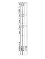
図3に示した表図はパターン位置の線型誤差の各成分を倍率X,倍率Y,直交度の順に示したものである。この線型誤差は Leica社製LMS IPROで測定した値であり、第1の実施の形態での線型誤差がショットの線型誤差と露光装置ステージの線型誤差との相対的なものであったのに対し、表図の値は絶対的な線型誤差である。Reticle の数値はレチクル単体での線型誤差で、 Patternとは露光装置を用いてこのレチクルを露光した基板上での線型誤差である。
【0025】
若しも露光装置で線型誤差に関して何の変動も受けない揚合は Reticleと Patternの項は全く等しくなるはずが、実際には露光装置自体が線型誤差成分を有するため、 Reticleと Patternとは異なった数値を示す。つまり、この数値の差が露光装置固有の線型誤差であり、この値は一定値を示す。
【0026】
それ故、レチクル単体での線型誤差と露光装置固有の線型誤差がわかっていれば、レチクルを変えて露光する場合でも、実際の露光を行わなうことなく、露光後の被転写基板上でのパターン位置の線型誤差が予測できる。また、露光装置ステージの線型誤差も一定値を示すため、実際の露光を行わずとも、転写されるパターン位置と露光装置ステージとの相対的な線型誤差がわかる。
【0027】
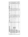
図4の表図は具体的に行った補正の数値を一覧として示したものである。ここで、レチクルをa、露光装置をb、パターンをc、ステージをd、補正値をeとすると、d,a、bは独立で、c=a+b,e=c−dの関係がある。
【0028】
本実施の形態では、上記差を補正値としてステージの座標系を補正することによって被転写基板上でパターン位置を高精度に制御することができる。
【0029】
本発明の露光方法の第3の実施の形態を説明する。
【0030】
上記した実施の形態においては使用するレチクルが1枚の揚合について述べたが、本実施の形態では2枚のレチクルを使用して位置精度を向上させる方法について述べる。使用するレチクルが1枚の場合と複数枚の場合との大きな違いは、レチクルが1枚の場合、ショット内でのパターン位置の線型誤差と露光装置ステージの線型誤差を相対的に合わせることで、線型誤差の各成分を0にすることが可能である。しかし、複数枚のレチクルを使用する場合では各レチクルがそれぞれ線型誤差を有しているため、完全に線型誤差を除去することはできない。
【0031】
図5は線型誤差の異なる2枚のレチクル、 ReticleAと ReticleBを使用して基板上で高精度のパターン位置を実現した場合の線形誤差成分を示した表図である。但し、レチクルAをa、レチクルBをb、レチクルB補正をc、レチクル平均をd、露光装置をe、パターンをf、ステージをg、補正値をhとすると、a,b,e,gは独立、cx=bx+{(ax+ay)/2−(bx+by)/2} cy=by+{(ax+ay)/2−(bx+by)/2} d=(a+c)/2の関係がある。
【0032】
まず、 ReticleA及び ReticleB単体での線型誤差を測定する。この結果、 ReticleAのX,Yの倍率誤差の平均値が−1.05[ppm]、 ReticleBの倍率誤差の平均値が0.6[ppm]であることがわかった。
【0033】
ReticleBの平均倍率を ReticleAの平均倍率に合わせるため平均倍率の差1.65[ppm]を ReticleBの露光時に補正することにした。その結果 ReticleAと ReticleBの平均倍率誤差は等しくなる。倍率誤差をX,Y方向の平均誤差として扱ったのは、今回使用したNSR12005111Dでは倍率誤差をX,Y別々に補正できないためである。今回は ReticleBを ReticleAに合わせたが、逆に ReticleAを ReticleBに合わせることも可能で、また両方のレチクルを補正してステージの倍率に合わせてしまうことも可能である。
【0034】
次に ReticleAと補正後の ReticleBの各成分を平均化したものが Reticle平均の項となる。平均を取る理由は、異なる線型誤差を有するものを合わせて補正する場合、補正値として各成分の平均値をとることによって最も誤差が小さくなることによる。この線型誤差の平均値をレチクルの代表値として第2の実施の形態で行ったのと同様に露光装置による定数分を加算したものが基板上での位置誤差の線型成分となる。
【0035】
本実施の形態によれば、露光装置のステージの線型誤差と上記パターンの線型誤差の差を補正するようにステージを制御することにより、線型誤差の少ないパターンが複数枚のレチクルを使用して露光可能となる。
【0036】
本発明の露光方法の第4の実施の形態を説明する。
【0037】
上記第3の実施の形態では、使用する原版が2枚で原版間の線型誤差の成分が各レチクル毎で違う場合についての補正について述べた。補正の方法としては各レチクルでX倍率とY倍率の平均が等しくなろようにショット時に光学的な倍率補正を加える。
【0038】
ステージ動作の補正は、前記補正をした後のX倍率,Y倍率,直交度のレチクル間の平均値をもってレチクル全体の代表値とし、第2の実施の形態で説明したレチクルが1枚である時と同様の方法を用いる。
【0039】
この方法は線型誤差の異なるレチクルを使用して被転写基板上で高精度なパターン位置を得るのに最適な方法ではあるが、上記第3の実施の形態のようにReticleAとReticle Bとで線型誤差の各成分の値が大きく異なっていると、例え補正を行ったとしても、被転写基板で得られるパターン位置精度は限られたものになってしまう。これは使用する原版が1枚の時と複数枚の時を比較すれば容易に理解することができる。
【0040】
つまり、レチクルが1枚の場合はレチクル自体の線型誤差とレチクルの線型誤差の代表値は等しいのに対して、複数枚使用する場合は各レチクル自体の線型誤差とレチクルの線型誤差の代表値は異なる。それ故、各レチクルで完全には線型誤差を除去することができず、被転写基板で実現できるパターン位置精度も限られたものになってしまう。
【0041】
このようにレチクルを1枚使う場合と複数枚使う場合では必ず1枚のレチクルを使う方が、達成できるパターン位置精度が高くなる。そこで、複数枚のレチクルを使用してレチクルを1枚使用する場合と同等のパターン位置精度を達成するためには、複数枚のレチクル間で線型誤差の各成分が等しければ良い。しかし、実際の原版はX倍率,Y倍率,直交度共に基板間で大きく異なる。
【0042】
図6は基板間でX倍率,Y倍率,直交度がどの程度異なるかを示した図である。横軸にレーザ描画装置によって描画した原版を時系列的に並べ、左軸に倍率をとり、右軸に直交度をとり、各原版の値をプロットした。
【0043】
レーザ描画装置でこの30枚の原版を描画するのに5日間を必要とした。この30枚の原版間における線型誤差の各成分のばらつきを正規分布で仮定し、ばらつきをσで表すと、X倍率が0.20[ppm],Y倍率が0.26[ppm],直交度が0.07[μrad]であった。
【0044】
若しも、この30枚の原版から使用する原版を2枚ランダムに選択して、この原版間の線型誤差の差を30枚から2枚を選ぶ全ての場合で平均すると、差の平均値は2×σ/√πとなる。具体的にはX倍率が0.23ppm,Y倍率が0.30ppm,直交度が0.07[μrad]となり、線型誤差の差が原版間で残ることになる。
【0045】
本例では、この原版間での差を最小にするために、使用する原版を必ず連続して描画して原版を作製する。図6に示された通り、5日間の描画でX倍率,Y倍率,直交度ともにドリフトを起こしており、これが上記のようにランダムに使用する原版を選択した時に原版間の差が小さくならない原因であった。
【0046】
しかし、連続して描画した原版を使用することにより、この描画装置によるドリフトの影響を最小に食い止めることが可能で、連続した原版を使用した場合の線型誤差の差はX倍率が0.09[ppm],Y倍率が0.05[ppm],直交度が0.03[μrad]であった。
【0047】
本実施の形態によれば、原版を連続して描画することにより,ランダムに原版を描画するよりも原版間の差を小さくすることが可能である。
【0048】
本発明の露光方法の第5の実施の形態を説明する。
【0049】
本例は線型誤差を補正できる機能を有する露光装置を用いた場合について述べる。被転写基板への露光には Nikon社製 NSR-S201Aを使用した。この露光装置はレチクルから転写を行う際にX,Y方向の倍率誤差を各方向毎に補正可能であり、直交度の補正も同時に行うことができる。そのため、第3の実施の形態で述べたような複数枚のレチクルを使用する場合で、レチクル毎に線型誤差が異なっている場合でも補正が可能となる。
【0050】
図7に示した表図を用いて ReticleCと ReticleDの2枚のレチクルを1枚の基板に転写した場合の具体的な補正方法について述ベる。 ReticleCと ReticleDとのレチクル自体の線型誤差は成分ごとに異なっている。ここで行ったのは転写後のパターンの線型誤差が ReticleC, ReticleDともにステージの線型誤差と合致するような補正を行った。露光装置で転写することによる線型誤差はあらかじめ測定されているので、その分を差し引いた補正を行う。
【0051】
ここで、ReticleCをa、ReticleDをb、ReticleC補正をc、ReticleD補正をd、露光装置をe、パターンをf、ステージをgとすると、a,b,e,g独立、a→c、b→d c,dは補正後の係数、f=g…(1) f=c+e or f=d+e…(2)
(1),(2)を満たすように補正する。
【0052】
各々の線型誤差成分を、倍率X,倍率Y,直交度の順に括弧で括って表記すると、ステージの線型誤差は(0.4,0.2,−0.4)となり、転写後のパターンがこの数値を満たせば、被転写基板上の位置誤差で線型誤差が複合されることがなくなる。
【0053】
露光装置で加算される線型誤差が(0.2,0.5,0.1)であるため、ステージの線型誤差から露光装置の成分を差し引いたもの(0.2,−0.3,−0.5)をレチクルの線型誤差が満たせば良い。
【0054】
ReticleCのレチクル自体の線型誤差が(−0.8,−0.3,0.6)であるから、転写時の補正は(1.0,0,−1.1)となり、 ReticleDではレチクル自体の線型誤差が(0.1,0.5,−0.4)であるから転写時の補正は(0.1,−0.8,−0.1)となる。
【0055】
このようにして求めた補正係数で各レチクルを転写することにより、被転写基板上での線型誤差はステージの値に統−された。よって、被転写基板上のパターン位置誤差はショット内の線型誤差及びステージの線型誤差との複合となるが両誤差は同じ値であるため、この誤差も線型誤差となる。
【0056】
これらの補正過程を図8に模式的に示す。この図8では ReticleCと ReticleDを被転写基板上に各2ショットずつ互いの境界が接するように露光を行った。上段に示したように ReticleCと ReticleDはレチクル自体の線型誤差が成分毎に異なるため、そのままで露光を行うと、図11で示したのと同様に被転写基板上での位置誤差は大変大きいものとなる。
【0057】
しかし、 ReticleCと ReticleDを上記の方法により補正を加えて露光することにより、図8の下段に示したようなショット同士の境界が重なるような露光結果を得ることができた。このようにして被転写基板上での線型誤差を除いた後の残留誤差はX,Y方向でそれぞれ18,20nmであり、この基板をレチクルとして使用するのに問題がないことがわかった。
【0058】
上記実施の形態ではステージ動作のもつ線型誤差を残したままで被転写基板の露光を行った。そのため、被転写基板上に実現されるパターンもステージの線型誤差を引きずることになる。被転写基板に線型誤差が残留していても問題が生じない場合もあるが、線型誤差を極力抑えたい場合にはステージ動作の線型誤差を取り除いてやる必要がある。
【0059】
図9に示した表図のようなReticle C及びReticle Dを使用する場合、露光装置固有の線型誤差をキャンセルするように露光条件を設定することで、被転写基板上のショット内の線型誤差を排除することができる。ステージ動作の線型誤差を取り除くことで、ショット間の線型誤差はなくなっている。
【0060】
本実施の形態によれば、ショット内、ショット間ともに線型誤差を排除できたため、被転写基板上に転写されるパターンは線型誤差を持たず理想的なパターン位置を実現することができる。
【0061】
【発明の効果】
以上詳細に説明したように、本発明によれば、被転写基板上でショット内のパターン位置の線型誤差とショット重心間の相対位置との線型誤差が等しくなり、複合された誤差も線型誤差となる。そのため、被転写基板上で線形誤差を除去できるような場合に残留するのはランダム誤差のみとなるため、高精度なパターン位置をもつ基板が作製可能となる。
【0062】
また、本発明によれば、使用する露光装置固有の線型誤差を把握することにより、レチクルを交換するたびに基板に転写、パターン位置の測定、補正値を導出、再度露光という煩雑な工程を経ず、1回の露光でパターン位置精度の高い基板を得ることができる。
【0063】
また、本発明によれば、線型誤差を独立に補正できない露光装置で複数枚の基板を使う場合、完全にショット内の線型誤差とショット自体の位置との線型誤差を無くすことはできないが、被転写基板上での残留誤差を最小にすることができる。
【0064】
また、本発明によれば、連続して描画したレクチルを使用することによりレクチル間の線形誤差を抑制し、請求項2記載の補正をより効果的なものにする。これにより複数枚のレクチルを使用する場合でも請求項1と同様にレクチルの線形誤差とステージ動作の線形誤差を合わせることができる。
【図面の簡単な説明】
【図1】本発明の露光方法の第1の実施の形態を説明する模式図である。
【図2】本発明の露光方法の第1の実施の形態を説明する他の模式図である。
【図3】本発明の露光方法の第2の実施の形態における線型誤差成分表を示した表図である。
【図4】本発明の露光方法の第2の実施の形態における別の線型誤差成分表を示した表図である。
【図5】本発明の露光方法の第3の実施の形態における線型誤差成分表を示した表図である。
【図6】本発明の露光方法の第4の実施の形態における基板間でX倍率,Y倍率,直交度がどの程度異なるかを示した特性図である。
【図7】本発明の露光方法の第5の実施の形態における線型誤差成分表を示した表図である。
【図8】本発明の露光方法の第5の実施の形態の補正過程を説明する模式図である。
【図9】本発明の露光方法の第5の実施の形態における線型誤差成分表を示した表図である。
【図10】線型誤差を含まない理想的な条件下における露光方法を説明する模式図である。
【図11】従来の露光方法を説明する模式図である。
【符号の説明】
11 ショット境界
12 パターン
13 パターン座標系
14 ステージ座標系[0001]
BACKGROUND OF THE INVENTION
The present invention relates to an exposure method for transferring a pattern to a substrate using an exposure apparatus, and particularly when high accuracy is required for the position accuracy of the pattern on the substrate.
[0002]
[Prior art]
Conventionally, when transferring a pattern using an exposure apparatus, especially when transferring to a blank substrate that has not been exposed to anything, the magnification of the reticle used for transfer, the orthogonality error, the magnification by the optical system of the exposure apparatus, The orthogonality error and the linear error such as the magnification of the exposure apparatus stage and the orthogonality error were not considered.
[0003]
For example, when a plurality of shots are exposed on one transfer substrate using a single reticle so that the boundaries are in contact with each other, shots are shot as shown in FIG. 10 under ideal conditions that do not include linear errors. The pattern shown by the cross in the shot is also on the Cartesian coordinate system.
[0004]
However, in actual exposure, the position error of the transferred pattern is very large because it includes all the errors. Further, since the position error on the transfer substrate is a combination of the plurality of linear errors, it becomes a non-linear error instead of a linear error. FIG. 11 schematically shows these position errors. Ideally, shot boundaries should be in contact with each other, but because the reference lengths of the shot and the stage are different, the boundaries are separated. Ideally, the cross pattern that should be at the intersection of the dotted lines is shifted from a predetermined position.
[0005]
[Problems to be solved by the invention]
The position error described above has been allowed so far, it is only necessary to manage the overlay accuracy with other layers on the substrate, and the position error becomes a problem only in the shot transferred by the exposure apparatus. Because it was. However, when the positional accuracy of the pattern on the substrate itself is required, for example, when it is desired to further improve the accuracy of overlay exposure with other layers on the substrate, when using this transfer substrate as a reticle, When the desired pattern is obtained by combining the reticles, there is a problem that the required positional accuracy cannot be achieved by the exposure method as described above.
[0006]
The present invention has been made to solve the conventional problems as described above, and an object of the present invention is to provide an exposure method capable of exposing a pattern position on a substrate with high accuracy.
[0007]
[Means for Solving the Problems]
In order to achieve the above object, the present invention is characterized in that, in an exposure method for forming a pattern by a plurality of shots on a substrate to be transferred by exposing the original plate a plurality of times, each shot on the substrate to be transferred Correction of the moving distance and direction of the stage on which the substrate to be transferred is placed so that the linear error such as the magnification and orthogonality of the pattern position and the linear error such as the magnification and orthogonality of the position for each shot are equal for each component. It is in.
[0010]
Another feature of the present invention is that in the exposure method for forming a plurality of patterns on the substrate by exposing the substrate placed on the stage of the exposure apparatus a plurality of times using at least one mask, Determining the first position linear error of the formed pattern, the second position linear error generated by the exposure apparatus during pattern transfer, and the third position linear error of the stage of the exposure apparatus; Adjusting the adjustment element of the exposure apparatus or adjusting the movement of the stage so that the second and third position linear errors are equal to each other.
[0011]
Another feature of the present invention is that in each exposure method, a linear pattern error component can be independently corrected, and a plurality of original plates are exposed multiple times to form a pattern of a plurality of shots on a transferred substrate. The exposure condition is corrected for each original used so that the linear error such as the magnification and orthogonality of the pattern position in the pattern and the linear error such as the magnification and orthogonality of the position for each shot are equal for each component.
[0012]
DETAILED DESCRIPTION OF THE INVENTION
Hereinafter, embodiments of the present invention will be described with reference to the drawings. First, a first embodiment of the exposure method of the present invention will be described.
[0013]
In this example, NSR-2005i11D manufactured by Nikon having a mechanism for correcting a part of linear errors due to the optical system of the exposure apparatus is used, and a linear error is allowed among the errors in the transfer substrate.
[0014]
The linear error that can be corrected in NSR-2005i11D is optical magnification correction, and X direction and Y direction cannot be corrected independently. The reason why linear error is allowed in the transferred substrate is that, for example, when this substrate is a reticle used in the Nikon NSR-S201A, all linear errors can be corrected. The error is not a problem.
[0015]
An example in which one reticle is used for exposure and the boundaries between the shots overlap will be described below. The linear error of the pattern position in the shot measured on the transferred substrate by the reticle used was the following numerical value.
[0016]
In the magnification error, the X direction was −1.2 [ppm], the Y direction was −0.8 [ppm], and the orthogonality error was −1.1 [μrad]. These numerical values are relative errors based on the stage of the exposure apparatus when no correction is applied to the stage of the exposure apparatus.
[0017]
In deriving the numerical values, the reticle was exposed to an 8-inch wafer as a transfer substrate and developed to form a pattern, and the transfer substrate was measured using LMS IPRO manufactured by Leica.
[0018]
FIG. 1 schematically shows the result of exposing the reticle with only the accuracy of the stage as in the prior art. The alignment in the X direction is taken between the pattern transferred to remove the rotational component of the linear error and the stage of the exposure apparatus. At this time, the residual error of the pattern position excluding the linear component was 3σ and 64 and 52 nm in the X and Y directions, respectively.
[0019]
As described above, there is a magnification error of −1.2 [ppm] in the X direction and −0.8 [ppm] in the Y direction, and the movement of the stage is larger than the size of the exposure shot. I'm away. Since a 20 mm square shot was exposed, the shift amounts Δx and Δy of the shot boundary in the X and Y directions were 24 and 16 nm, respectively.
[0020]
FIG. 1 shows the result of exposure with magnification correction applied to the moving distance of the stage in order to correct this shift amount. The correction numerical values are −1.2 [ppm] and −0.8 [ppm] in the X and Y directions, respectively, the coordinate system before correction is (X, Y), and the coordinate system after correction is (X ′, Y ′), The relational expression is as follows.
[0021]
X ′ = (1-1−2 × 10 −6) × X
Y ′ = (1−0.8 × 10 −6) × Y
As a result, it was possible to obtain an exposure result such that the shot boundary touched. At this time, the residual error excluding the linear component was 3σ, and 43 and 32 nm in the X and Y directions, respectively. However, since the orthogonality error between the exposure shot and the stage still remains at −1.1 [μrad], a shift of 22 nm occurs at the shot boundary. In order to correct this deviation, correction of the orthogonality was further added to the moving direction of the stage.
[0022]
The result of correcting the orthogonality of the stage coordinate system in addition to the magnification correction is as shown in FIG. Here, the shot boundary is completely in contact with each other, and the relative linear error between the shot position and the pattern position is eliminated, so the error that combines the shot linear error and the stage linear error on the transfer substrate is the linear error. It has become. The correction relational expression when the corrected coordinate system is (X ″, Y ″) is as follows.
[0023]
[Expression 1]
X ″ = X ′ = (1−1.2 × 10 −6) × X
Y ″ = Y′−1.1 × 10 −6 × X ′ = (1−0.8 × 10 −6) × Y−1.1 × 10 −6 × (1−1.2 × 10 −6) × X
According to the present embodiment, when the linear component is removed from the position error of the substrate exposed by correcting the stage, the linear error can be completely removed and the residual component is only random. The residual error after removing the linear error was 3σ, 15 and 17 nm in the X and Y directions, respectively, and very good results could be obtained. Thus, by eliminating the relative error between the linear component of the pattern exposed by the reticle and the linear component of the exposure apparatus stage, the pattern position on the transferred substrate can be controlled with high accuracy. A second embodiment of the exposure method of the present invention will be described. In deriving the relative error between the linear component of the pattern exposed by the reticle and the linear component of the exposure apparatus stage in the first embodiment, the substrate is actually exposed to measure the pattern on the substrate. Was going to be. In the present embodiment, a method for correcting without transferring a pattern to a substrate will be described.
[0024]
The table shown in FIG. 3 shows each component of the pattern position linear error in the order of magnification X, magnification Y, and orthogonality. This linear error is a value measured by Leica LMS IPRO, whereas the linear error in the first embodiment is a relative between the linear error of the shot and the linear error of the exposure apparatus stage. The values in the table are absolute linear errors. The Reticle value is the linear error of the reticle alone, and the Pattern is the linear error on the substrate that has been exposed to this reticle using an exposure apparatus.
[0025]
If the exposure system is not subject to any variation in linear error, the terms of Reticle and Pattern should be exactly the same, but actually the exposure system itself has a linear error component, so it differs from Reticle and Pattern. Indicates a numerical value. That is the difference the exposure apparatus specific linear error of the numerical value, the value shows a constant value.
[0026]
Therefore, if the linear error of the reticle alone and the linear error inherent to the exposure apparatus are known, even if the exposure is changed with the reticle, the actual exposure is not performed on the transferred substrate after exposure. The linear error of the pattern position can be predicted. Further, since the linear error of the exposure apparatus stage also shows a constant value, the relative linear error between the transferred pattern position and the exposure apparatus stage can be known without performing actual exposure.
[0027]
The table of FIG. 4 shows a list of the numerical values of the corrections made specifically. Here, assuming that the reticle is a, the exposure apparatus is b, the pattern is c, the stage is d, and the correction value is e, d, a and b are independent and have a relationship of c = a + b and e = cd.
[0028]
In this embodiment, the pattern position on the transfer substrate can be controlled with high accuracy by correcting the coordinate system of the stage using the difference as a correction value.
[0029]
A third embodiment of the exposure method of the present invention will be described.
[0030]
In the above-described embodiment, description has been made on the assembling of one reticle to be used, but in this embodiment, a method for improving positional accuracy by using two reticles will be described. The major difference between the case of using one reticle and the case of using a plurality of reticles is that when the reticle is one, the linear error of the pattern position in the shot and the linear error of the exposure apparatus stage are relatively matched. Each component of the linear error can be made zero. However, when a plurality of reticles are used, each reticle has a linear error. Therefore, the linear error cannot be completely removed.
[0031]
FIG. 5 is a table showing linear error components when a highly accurate pattern position is realized on a substrate using two reticles having different linear errors, Reticle A and Reticle B. FIG. However, assuming that reticle A is a, reticle B is b, reticle B correction is c, reticle average is d, exposure apparatus is e, pattern is f, stage is g, and correction value is h, a, b, e, g Are independent, cx = bx + {(ax + ay) / 2− (bx + by) / 2} cy = by + {(ax + ay) / 2− (bx + by) / 2} d = (a + c) / 2.
[0032]
First, the linear error of Reticle A and Reticle B alone is measured. As a result, it was found that the average value of the X, Y magnification errors of Reticle A was −1.05 [ppm], and the average value of the magnification errors of Reticle B was 0.6 [ppm].
[0033]
In order to adjust the average magnification of Reticle B to the average magnification of Reticle A, the difference of 1.65 [ppm] in the average magnification was corrected at the time of exposure of Reticle B. As a result, the average magnification errors of Reticle A and Reticle B are equal. The reason why the magnification error is treated as an average error in the X and Y directions is that the NSR 12005111D used this time cannot correct the magnification error separately for X and Y. This time, Reticle B is matched with Reticle A. Conversely, Reticle A can be matched with Reticle B, and both reticles can be corrected to match the stage magnification.
[0034]
Next, the average of each component of Reticle A and corrected Reticle B is the term of Reticle average. The reason for taking the average is that when correcting those having different linear errors, the error is minimized by taking the average value of each component as the correction value. The linear component of the position error on the substrate is obtained by adding the constants obtained by the exposure apparatus in the same manner as in the second embodiment using the average value of the linear error as the representative value of the reticle.
[0035]
According to the present embodiment, by controlling the stage so as to correct the difference between the linear error of the stage of the exposure apparatus and the linear error of the pattern, a pattern with a small linear error is exposed using a plurality of reticles. It becomes possible.
[0036]
A fourth embodiment of the exposure method of the present invention will be described.
[0037]
In the third embodiment, correction has been described for the case where two original plates are used and the linear error component between the original plates is different for each reticle. As a correction method, optical magnification correction is applied at the time of shot so that the average of the X magnification and the Y magnification is equal for each reticle.
[0038]
The stage movement is corrected when the average value among the reticles of the X magnification, Y magnification, and orthogonality after the correction is used as a representative value of the entire reticle, and the number of reticles described in the second embodiment is one. The same method is used.
[0039]
This method is an optimal method for obtaining a highly accurate pattern position on a transfer substrate using a reticle having different linear errors. However, as in the third embodiment, a linear type is used for Reticle A and Reticle B. If the values of the error components differ greatly, even if correction is performed, the pattern position accuracy obtained on the transferred substrate is limited. This can be easily understood by comparing the case of using one original and a plurality of originals.
[0040]
In other words, when the number of reticles is one, the reticle linear error and the reticle linear error are the same, but when using a plurality of reticles, the reticle linear error and the reticle linear error are Different. Therefore, the linear error cannot be completely removed by each reticle, and the pattern position accuracy that can be realized by the transfer substrate is limited.
[0041]
As described above, when one reticle is used and when a plurality of reticles are used, the pattern position accuracy that can be achieved is always higher when one reticle is used. Therefore, in order to achieve the same pattern position accuracy as when a single reticle is used by using a plurality of reticles, it is only necessary that the components of the linear error are equal between the plurality of reticles. However, the actual original plate varies greatly between substrates in terms of X magnification, Y magnification, and orthogonality.
[0042]
FIG. 6 is a diagram showing how the X magnification, Y magnification, and orthogonality differ between substrates. The originals drawn by the laser drawing apparatus were arranged in time series on the horizontal axis, the magnification was taken on the left axis, the orthogonality was taken on the right axis, and the values of each original were plotted.
[0043]
It took 5 days to draw the 30 original plates with the laser drawing apparatus. Assuming that the variation of each component of the linear error between the 30 original plates is assumed to be a normal distribution and the variation is expressed by σ, the X magnification is 0.20 [ppm], the Y magnification is 0.26 [ppm], and the orthogonality Was 0.07 [μrad].
[0044]
If two originals to be used are randomly selected from the 30 originals, and the linear error difference between the originals is averaged in all cases of selecting 30 to 2 originals, the average difference is 2 × σ / √π. Specifically, the X magnification is 0.23 ppm, the Y magnification is 0.30 ppm, and the orthogonality is 0.07 [μrad], so that a difference in linear error remains between the originals.
[0045]
In this example, in order to minimize the difference between the original plates, the original plate to be used is always drawn continuously to produce the original plate. As shown in FIG. 6, the X magnification, the Y magnification, and the orthogonality drifted in the drawing for 5 days. This is the reason why the difference between the original plates is not reduced when the original plate to be used at random is selected as described above. Met.
[0046]
However, by using the original drawn continuously, it is possible to suppress the influence of drift by this drawing apparatus to a minimum, and the difference in linear error when using the continuous original is 0.09 [ ppm], Y magnification was 0.05 [ppm], and orthogonality was 0.03 [μrad].
[0047]
According to the present embodiment, it is possible to reduce the difference between the original plates by drawing the original plates continuously, rather than drawing the original plates randomly.
[0048]
A fifth embodiment of the exposure method of the present invention will be described.
[0049]
This example describes a case where an exposure apparatus having a function capable of correcting a linear error is used. Nikon NSR-S201A was used for exposure of the transfer substrate. This exposure apparatus can correct magnification errors in the X and Y directions for each direction when transferring from the reticle, and can also correct the orthogonality at the same time. Therefore, when a plurality of reticles as described in the third embodiment are used, correction can be performed even when the linear errors differ for each reticle.
[0050]
A specific correction method when two reticles Reticle C and Reticle D are transferred to one substrate will be described using the table shown in FIG. The linear errors of Reticle C and Reticle D reticles themselves are different for each component. Here, the correction was made so that the linear error of the pattern after transfer coincides with the linear error of the stage for both ReticleC and ReticleD. Since the linear error due to the transfer by the exposure apparatus has been measured in advance, correction is performed by subtracting the error.
[0051]
Here, when Reticle C is a, Reticle D is b, Reticle C correction is c, Reticle D correction is d, exposure apparatus is e, pattern is f, and stage is g, a, b, e, g are independent, a → c, b → d c and d are coefficients after correction, f = g (1) f = c + e or f = d + e (2)
Corrections are made to satisfy (1) and (2).
[0052]
When each linear error component is expressed in parentheses in the order of magnification X, magnification Y, and orthogonality, the linear error of the stage is (0.4, 0.2, −0.4), and the pattern after transfer is If this numerical value is satisfied, the linear error is not compounded by the position error on the transfer substrate.
[0053]
Since the linear error added by the exposure apparatus is (0.2, 0.5, 0.1), the component of the exposure apparatus is subtracted from the linear error of the stage (0.2, -0.3,- 0.5) should satisfy the linear error of the reticle.
[0054]
Since the linear error of the Reticle C reticle itself is (−0.8, −0.3, 0.6), the correction at the time of transfer is (1.0, 0, −1.1). In Reticle D, the reticle itself is Since the linear error is (0.1, 0.5, -0.4), the correction during transfer is (0.1, -0.8, -0.1).
[0055]
By transferring each reticle with the correction coefficient thus obtained, the linear error on the transfer substrate is integrated with the value of the stage. Therefore, the pattern position error on the transfer substrate is a composite of the linear error in the shot and the linear error of the stage, but both errors have the same value, so this error also becomes a linear error.
[0056]
These correction processes are schematically shown in FIG. In FIG. 8, Reticle C and Reticle D were exposed on the substrate to be transferred so that the boundary between the two shots touched each other. Reticle C and Reticle D have different linear errors for each component as shown in the upper part. Therefore, if exposure is performed as it is, the position error on the transferred substrate is very large as shown in FIG. It becomes.
[0057]
However, by exposing Reticle C and Reticle D with correction by the above method, it was possible to obtain an exposure result in which the boundaries between shots overlapped as shown in the lower part of FIG. Thus, the residual errors after removing the linear error on the transferred substrate are 18 and 20 nm in the X and Y directions, respectively, and it has been found that there is no problem in using this substrate as a reticle.
[0058]
In the above embodiment, the substrate to be transferred is exposed while the linear error of the stage operation remains. For this reason, the pattern realized on the transferred substrate also drags the linear error of the stage. Although there may be no problem even if linear errors remain on the transferred substrate, it is necessary to eliminate the linear errors in the stage operation when it is desired to suppress the linear errors as much as possible.
[0059]
When using Reticle C and Reticle D as shown in the table of FIG. 9, the exposure condition is set so as to cancel the linear error inherent in the exposure apparatus, thereby reducing the linear error in the shot on the transferred substrate. Can be eliminated. By removing the linear error of the stage operation, the linear error between shots is eliminated.
[0060]
According to the present embodiment, since linear errors can be eliminated both within and between shots, the pattern transferred onto the substrate to be transferred has no linear errors, and an ideal pattern position can be realized.
[0061]
【The invention's effect】
As described above in detail, according to the present invention, the linear error of the pattern position in the shot on the transferred substrate and the linear error of the relative position between the shot centroids become equal, and the combined error is also a linear error. Become . For this reason, only the random error remains when the linear error can be removed on the transferred substrate, so that a substrate having a highly accurate pattern position can be manufactured.
[0062]
In addition, according to the present invention, by grasping the linear error inherent to the exposure apparatus to be used, each time the reticle is replaced, transfer to the substrate, measurement of the pattern position, derivation of a correction value, and a complicated process of exposure again are performed. In addition, a substrate with high pattern position accuracy can be obtained by one exposure.
[0063]
Further , according to the present invention, when a plurality of substrates is used in an exposure apparatus that cannot independently correct linear errors, the linear error between the shot and the position of the shot itself cannot be completely eliminated. Residual errors on the transfer substrate can be minimized.
[0064]
In addition, according to the present invention, linear errors between the reticles are suppressed by using continuously drawn reticles, and the correction according to claim 2 is made more effective. Thus, even when a plurality of reticles are used, the linear error of the reticle and the linear error of the stage operation can be matched as in the first aspect.
[Brief description of the drawings]
FIG. 1 is a schematic diagram for explaining a first embodiment of an exposure method of the present invention.
FIG. 2 is another schematic diagram for explaining the first embodiment of the exposure method of the present invention.
FIG. 3 is a table showing a linear error component table in a second embodiment of the exposure method of the present invention.
FIG. 4 is a table showing another linear error component table in the second embodiment of the exposure method of the present invention.
FIG. 5 is a table showing a linear error component table in a third embodiment of the exposure method of the present invention.
FIG. 6 is a characteristic diagram showing how the X magnification, the Y magnification, and the orthogonality differ between substrates in the fourth embodiment of the exposure method of the present invention.
FIG. 7 is a table showing a linear error component table in the fifth embodiment of the exposure method of the present invention.
FIG. 8 is a schematic diagram for explaining the correction process of the fifth embodiment of the exposure method of the present invention.
FIG. 9 is a table showing a linear error component table in the fifth embodiment of the exposure method of the present invention.
FIG. 10 is a schematic diagram illustrating an exposure method under ideal conditions that do not include linear errors.
FIG. 11 is a schematic diagram for explaining a conventional exposure method.
[Explanation of symbols]
11 Shot boundary 12 Pattern 13 Pattern coordinate system 14 Stage coordinate system
Claims (6)
前記被転写基板上における各ショット内のパターン位置の倍率及び直交度などの線型誤差とショット毎の位置の倍率及び直交度などの線型誤差が各成分で等しくなるように、前記被転写基板を載せるステージの移動距離と方向を補正することを特徴とする露光方法。In an exposure method for forming a pattern by a plurality of shots on a transfer substrate by exposing the original plate a plurality of times,
The transferred substrate is mounted so that the linear error such as the magnification and orthogonality of the pattern position in each shot on the transferred substrate and the linear error such as the magnification and orthogonality of the position for each shot are equal for each component. An exposure method comprising correcting a moving distance and direction of a stage.
この平均倍率を合わせた後の直交度、X倍率、Y倍率で表される線型誤差の各成分の平均値をレチクルの代表値として前記補正を行うことを特徴とする請求項1又は2記載の露光方法。When the exposure apparatus to be used is capable of only magnification correction and uses a plurality of original plates, the average magnification in the X and Y directions between the original plates is adjusted,
3. The correction according to claim 1, wherein the correction is performed by using an average value of linear error components represented by orthogonality, X magnification, and Y magnification after combining the average magnifications as a representative value of the reticle. Exposure method.
各ショット内のパターン位置の倍率及び直交度などの線型誤差とショット毎の位置の倍率及び直交度などの線型誤差が各成分で等しくなるように使用する原版毎に露光条件を補正することを特徴とする露光方法。In the exposure method in which each component of the linear error can be independently corrected and a plurality of original plates are exposed multiple times to form a pattern by a plurality of shots on the transferred substrate.
The exposure condition is corrected for each original used so that the linear error such as the magnification and orthogonality of the pattern position in each shot and the linear error such as the magnification and orthogonality of the position for each shot are equal for each component. Exposure method.
前記マスクによって形成されたパターンの第1の位置線型誤差および前記露光装置がパターン転写時に生ぜしめる第2の位置線型誤差および前記露光装置のステージが有する第3の位置線型誤差を求めるステップとDetermining a first position linear error of the pattern formed by the mask, a second position linear error generated by the exposure apparatus during pattern transfer, and a third position linear error of the stage of the exposure apparatus;
前記第1、第2および第3の位置線型誤差が相互に等しくなるように前記露光装置の調整要素を調整する、あるいは前記ステージの移動を調整するステップとを有することを特徴とする露光方法。Adjusting the adjustment element of the exposure apparatus or adjusting the movement of the stage so that the first, second and third position linear errors are equal to each other.
Priority Applications (2)
| Application Number | Priority Date | Filing Date | Title |
|---|---|---|---|
| JP06070899A JP3929635B2 (en) | 1999-03-08 | 1999-03-08 | Exposure method |
| US09/520,630 US6542237B1 (en) | 1999-03-08 | 2000-03-07 | Exposure method for making precision patterns on a substrate |
Applications Claiming Priority (1)
| Application Number | Priority Date | Filing Date | Title |
|---|---|---|---|
| JP06070899A JP3929635B2 (en) | 1999-03-08 | 1999-03-08 | Exposure method |
Publications (3)
| Publication Number | Publication Date |
|---|---|
| JP2000260689A JP2000260689A (en) | 2000-09-22 |
| JP2000260689A5 JP2000260689A5 (en) | 2005-06-30 |
| JP3929635B2 true JP3929635B2 (en) | 2007-06-13 |
Family
ID=13150070
Family Applications (1)
| Application Number | Title | Priority Date | Filing Date |
|---|---|---|---|
| JP06070899A Expired - Fee Related JP3929635B2 (en) | 1999-03-08 | 1999-03-08 | Exposure method |
Country Status (2)
| Country | Link |
|---|---|
| US (1) | US6542237B1 (en) |
| JP (1) | JP3929635B2 (en) |
Families Citing this family (3)
| Publication number | Priority date | Publication date | Assignee | Title |
|---|---|---|---|---|
| JP2002224604A (en) * | 2001-01-31 | 2002-08-13 | Hitachi Ltd | Pattern transfer apparatus, pattern transfer method and method for manufacturing original plate for transfer |
| US7171637B2 (en) * | 2005-01-14 | 2007-01-30 | Intel Corporation | Translation generation for a mask pattern |
| JP2017090817A (en) * | 2015-11-16 | 2017-05-25 | キヤノン株式会社 | Exposure apparatus and article manufacturing method |
Family Cites Families (11)
| Publication number | Priority date | Publication date | Assignee | Title |
|---|---|---|---|---|
| US4918320A (en) | 1987-03-20 | 1990-04-17 | Canon Kabushiki Kaisha | Alignment method usable in a step-and-repeat type exposure apparatus for either global or dye-by-dye alignment |
| US5243195A (en) * | 1991-04-25 | 1993-09-07 | Nikon Corporation | Projection exposure apparatus having an off-axis alignment system and method of alignment therefor |
| US5798195A (en) * | 1993-09-24 | 1998-08-25 | Nikon Corporation | Stepping accuracy measuring method |
| KR100377887B1 (en) * | 1994-02-10 | 2003-06-18 | 가부시키가이샤 니콘 | Sort method |
| JPH07260472A (en) * | 1994-03-22 | 1995-10-13 | Nikon Corp | Orthogonality measuring method for stage device |
| JPH0845814A (en) * | 1994-07-27 | 1996-02-16 | Nikon Corp | Exposure device and positioning method |
| JP3261948B2 (en) * | 1995-03-28 | 2002-03-04 | キヤノン株式会社 | X-ray exposure mask and method for manufacturing semiconductor device using the same |
| KR100471461B1 (en) * | 1996-05-16 | 2005-07-07 | 가부시키가이샤 니콘 | Exposure method and exposure apparatus |
| AU6000499A (en) * | 1998-09-30 | 2000-04-17 | Nikon Corporation | Alignment method and method for producing device using the alignment method |
| JP3751762B2 (en) * | 1998-12-08 | 2006-03-01 | 株式会社東芝 | Semiconductor device manufacturing method and original plate |
| JP3831138B2 (en) * | 1999-01-28 | 2006-10-11 | 株式会社東芝 | Pattern formation method |
-
1999
- 1999-03-08 JP JP06070899A patent/JP3929635B2/en not_active Expired - Fee Related
-
2000
- 2000-03-07 US US09/520,630 patent/US6542237B1/en not_active Expired - Fee Related
Also Published As
| Publication number | Publication date |
|---|---|
| JP2000260689A (en) | 2000-09-22 |
| US6542237B1 (en) | 2003-04-01 |
Similar Documents
| Publication | Publication Date | Title |
|---|---|---|
| US7842442B2 (en) | Method and system for reducing overlay errors within exposure fields by APC control strategies | |
| US5308991A (en) | Method and apparatus for making a predistorted reticle to compensate for lens distortions | |
| JPH10289861A (en) | Method for forming mask pattern | |
| CN114207527B (en) | Method for controlling semiconductor manufacturing process | |
| KR101421258B1 (en) | A method and a system for reducing overlay errors within exposure fields by apc control strategies | |
| KR102326191B1 (en) | Device manufacturing process | |
| JP2010502024A5 (en) | ||
| JP3929635B2 (en) | Exposure method | |
| KR20070106938A (en) | Exposure apparatus and method, and device manufacturing method | |
| CN112585538B (en) | Method for controlling a manufacturing process and associated device | |
| JP2004071978A (en) | Method for managing exposure device, method for managing mask, method for exposure, and method for manufacturing semiconductor device | |
| US11709434B2 (en) | Device manufacturing method | |
| EP3783437A1 (en) | Device manufacturing method | |
| CN115576173A (en) | Method for improving alignment precision | |
| US6456953B1 (en) | Method for correcting misalignment between a reticle and a stage in a step-and-repeat exposure system | |
| JPH0251214A (en) | Manufacture of semiconductor device | |
| Arendt et al. | Optical Run-Out Correction for Improved Lithography Overlay Accuracy for Fowlp Applications | |
| KR100791689B1 (en) | Mask fabrication method of semiconductor device | |
| JPS6214935B2 (en) | ||
| JPS63131143A (en) | Photomask | |
| JPS62245265A (en) | Manufacture of lithographic mask | |
| JPH04215418A (en) | Manufacture of semiconductor device | |
| JPH04107465A (en) | Exposing for reduction stepper | |
| KR20040074799A (en) | Method for correcting line-width variation by stage tilt | |
| JPH03246921A (en) | Manufacture of semiconductor device |
Legal Events
| Date | Code | Title | Description |
|---|---|---|---|
| A521 | Request for written amendment filed |
Free format text: JAPANESE INTERMEDIATE CODE: A523 Effective date: 20041022 |
|
| A621 | Written request for application examination |
Free format text: JAPANESE INTERMEDIATE CODE: A621 Effective date: 20041022 |
|
| A977 | Report on retrieval |
Free format text: JAPANESE INTERMEDIATE CODE: A971007 Effective date: 20060621 |
|
| TRDD | Decision of grant or rejection written | ||
| A01 | Written decision to grant a patent or to grant a registration (utility model) |
Free format text: JAPANESE INTERMEDIATE CODE: A01 Effective date: 20070227 |
|
| A61 | First payment of annual fees (during grant procedure) |
Free format text: JAPANESE INTERMEDIATE CODE: A61 Effective date: 20070307 |
|
| FPAY | Renewal fee payment (event date is renewal date of database) |
Free format text: PAYMENT UNTIL: 20100316 Year of fee payment: 3 |
|
| FPAY | Renewal fee payment (event date is renewal date of database) |
Free format text: PAYMENT UNTIL: 20110316 Year of fee payment: 4 |
|
| FPAY | Renewal fee payment (event date is renewal date of database) |
Free format text: PAYMENT UNTIL: 20120316 Year of fee payment: 5 |
|
| LAPS | Cancellation because of no payment of annual fees |