JP3927240B2 - Disposable microprocessor controlled walking capacity pump - Google Patents
Disposable microprocessor controlled walking capacity pump Download PDFInfo
- Publication number
- JP3927240B2 JP3927240B2 JP54013297A JP54013297A JP3927240B2 JP 3927240 B2 JP3927240 B2 JP 3927240B2 JP 54013297 A JP54013297 A JP 54013297A JP 54013297 A JP54013297 A JP 54013297A JP 3927240 B2 JP3927240 B2 JP 3927240B2
- Authority
- JP
- Japan
- Prior art keywords
- pump
- fluid
- flow path
- disposed
- membrane
- Prior art date
- Legal status (The legal status is an assumption and is not a legal conclusion. Google has not performed a legal analysis and makes no representation as to the accuracy of the status listed.)
- Expired - Fee Related
Links
Images


Classifications
-
- F—MECHANICAL ENGINEERING; LIGHTING; HEATING; WEAPONS; BLASTING
- F04—POSITIVE - DISPLACEMENT MACHINES FOR LIQUIDS; PUMPS FOR LIQUIDS OR ELASTIC FLUIDS
- F04B—POSITIVE-DISPLACEMENT MACHINES FOR LIQUIDS; PUMPS
- F04B7/00—Piston machines or pumps characterised by having positively-driven valving
- F04B7/0003—Piston machines or pumps characterised by having positively-driven valving the distribution member forming both the inlet and discharge distributor for one single pumping chamber
- F04B7/0015—Piston machines or pumps characterised by having positively-driven valving the distribution member forming both the inlet and discharge distributor for one single pumping chamber and having a slidable movement
-
- A—HUMAN NECESSITIES
- A61—MEDICAL OR VETERINARY SCIENCE; HYGIENE
- A61M—DEVICES FOR INTRODUCING MEDIA INTO, OR ONTO, THE BODY; DEVICES FOR TRANSDUCING BODY MEDIA OR FOR TAKING MEDIA FROM THE BODY; DEVICES FOR PRODUCING OR ENDING SLEEP OR STUPOR
- A61M5/00—Devices for bringing media into the body in a subcutaneous, intra-vascular or intramuscular way; Accessories therefor, e.g. filling or cleaning devices, arm-rests
- A61M5/14—Infusion devices, e.g. infusing by gravity; Blood infusion; Accessories therefor
- A61M5/142—Pressure infusion, e.g. using pumps
-
- F—MECHANICAL ENGINEERING; LIGHTING; HEATING; WEAPONS; BLASTING
- F04—POSITIVE - DISPLACEMENT MACHINES FOR LIQUIDS; PUMPS FOR LIQUIDS OR ELASTIC FLUIDS
- F04B—POSITIVE-DISPLACEMENT MACHINES FOR LIQUIDS; PUMPS
- F04B17/00—Pumps characterised by combination with, or adaptation to, specific driving engines or motors
- F04B17/03—Pumps characterised by combination with, or adaptation to, specific driving engines or motors driven by electric motors
-
- F—MECHANICAL ENGINEERING; LIGHTING; HEATING; WEAPONS; BLASTING
- F04—POSITIVE - DISPLACEMENT MACHINES FOR LIQUIDS; PUMPS FOR LIQUIDS OR ELASTIC FLUIDS
- F04B—POSITIVE-DISPLACEMENT MACHINES FOR LIQUIDS; PUMPS
- F04B49/00—Control, e.g. of pump delivery, or pump pressure of, or safety measures for, machines, pumps, or pumping installations, not otherwise provided for, or of interest apart from, groups F04B1/00 - F04B47/00
- F04B49/12—Control, e.g. of pump delivery, or pump pressure of, or safety measures for, machines, pumps, or pumping installations, not otherwise provided for, or of interest apart from, groups F04B1/00 - F04B47/00 by varying the length of stroke of the working members
-
- F—MECHANICAL ENGINEERING; LIGHTING; HEATING; WEAPONS; BLASTING
- F04—POSITIVE - DISPLACEMENT MACHINES FOR LIQUIDS; PUMPS FOR LIQUIDS OR ELASTIC FLUIDS
- F04B—POSITIVE-DISPLACEMENT MACHINES FOR LIQUIDS; PUMPS
- F04B53/00—Component parts, details or accessories not provided for in, or of interest apart from, groups F04B1/00 - F04B23/00 or F04B39/00 - F04B47/00
- F04B53/02—Packing the free space between cylinders and pistons
-
- F—MECHANICAL ENGINEERING; LIGHTING; HEATING; WEAPONS; BLASTING
- F04—POSITIVE - DISPLACEMENT MACHINES FOR LIQUIDS; PUMPS FOR LIQUIDS OR ELASTIC FLUIDS
- F04B—POSITIVE-DISPLACEMENT MACHINES FOR LIQUIDS; PUMPS
- F04B53/00—Component parts, details or accessories not provided for in, or of interest apart from, groups F04B1/00 - F04B23/00 or F04B39/00 - F04B47/00
- F04B53/16—Casings; Cylinders; Cylinder liners or heads; Fluid connections
- F04B53/162—Adaptations of cylinders
- F04B53/164—Stoffing boxes
-
- F—MECHANICAL ENGINEERING; LIGHTING; HEATING; WEAPONS; BLASTING
- F04—POSITIVE - DISPLACEMENT MACHINES FOR LIQUIDS; PUMPS FOR LIQUIDS OR ELASTIC FLUIDS
- F04B—POSITIVE-DISPLACEMENT MACHINES FOR LIQUIDS; PUMPS
- F04B9/00—Piston machines or pumps characterised by the driving or driven means to or from their working members
- F04B9/02—Piston machines or pumps characterised by the driving or driven means to or from their working members the means being mechanical
- F04B9/04—Piston machines or pumps characterised by the driving or driven means to or from their working members the means being mechanical the means being cams, eccentrics or pin-and-slot mechanisms
- F04B9/045—Piston machines or pumps characterised by the driving or driven means to or from their working members the means being mechanical the means being cams, eccentrics or pin-and-slot mechanisms the means being eccentrics
-
- F—MECHANICAL ENGINEERING; LIGHTING; HEATING; WEAPONS; BLASTING
- F16—ENGINEERING ELEMENTS AND UNITS; GENERAL MEASURES FOR PRODUCING AND MAINTAINING EFFECTIVE FUNCTIONING OF MACHINES OR INSTALLATIONS; THERMAL INSULATION IN GENERAL
- F16K—VALVES; TAPS; COCKS; ACTUATING-FLOATS; DEVICES FOR VENTING OR AERATING
- F16K41/00—Spindle sealings
- F16K41/10—Spindle sealings with diaphragm, e.g. shaped as bellows or tube
- F16K41/12—Spindle sealings with diaphragm, e.g. shaped as bellows or tube with approximately flat diaphragm
-
- F—MECHANICAL ENGINEERING; LIGHTING; HEATING; WEAPONS; BLASTING
- F04—POSITIVE - DISPLACEMENT MACHINES FOR LIQUIDS; PUMPS FOR LIQUIDS OR ELASTIC FLUIDS
- F04B—POSITIVE-DISPLACEMENT MACHINES FOR LIQUIDS; PUMPS
- F04B2201/00—Pump parameters
- F04B2201/12—Parameters of driving or driven means
- F04B2201/1208—Angular position of the shaft
-
- F—MECHANICAL ENGINEERING; LIGHTING; HEATING; WEAPONS; BLASTING
- F04—POSITIVE - DISPLACEMENT MACHINES FOR LIQUIDS; PUMPS FOR LIQUIDS OR ELASTIC FLUIDS
- F04B—POSITIVE-DISPLACEMENT MACHINES FOR LIQUIDS; PUMPS
- F04B2205/00—Fluid parameters
- F04B2205/05—Pressure after the pump outlet
-
- F—MECHANICAL ENGINEERING; LIGHTING; HEATING; WEAPONS; BLASTING
- F05—INDEXING SCHEMES RELATING TO ENGINES OR PUMPS IN VARIOUS SUBCLASSES OF CLASSES F01-F04
- F05C—INDEXING SCHEME RELATING TO MATERIALS, MATERIAL PROPERTIES OR MATERIAL CHARACTERISTICS FOR MACHINES, ENGINES OR PUMPS OTHER THAN NON-POSITIVE-DISPLACEMENT MACHINES OR ENGINES
- F05C2225/00—Synthetic polymers, e.g. plastics; Rubber
- F05C2225/04—PTFE [PolyTetraFluorEthylene]
Landscapes
- Engineering & Computer Science (AREA)
- General Engineering & Computer Science (AREA)
- Mechanical Engineering (AREA)
- Health & Medical Sciences (AREA)
- Animal Behavior & Ethology (AREA)
- Veterinary Medicine (AREA)
- Biomedical Technology (AREA)
- Heart & Thoracic Surgery (AREA)
- Hematology (AREA)
- Life Sciences & Earth Sciences (AREA)
- Vascular Medicine (AREA)
- General Health & Medical Sciences (AREA)
- Public Health (AREA)
- Anesthesiology (AREA)
- Infusion, Injection, And Reservoir Apparatuses (AREA)
- Reciprocating Pumps (AREA)
- Pharmaceuticals Containing Other Organic And Inorganic Compounds (AREA)
- Saccharide Compounds (AREA)
- External Artificial Organs (AREA)
- Control Of Positive-Displacement Pumps (AREA)
- Massaging Devices (AREA)
Abstract
Description
発明の背景
本出願は1993年11月23日出願のVOLUMETRIC PUMP/VALVEと題した出願第08/157,693号の一部継続出願である。
本発明は、静脈内(IV)治療システムなどの医療システムを含む種々の用途に適した、軽量で安価な歩行容量ポンプに関する。
患者への流体の静脈内投与は、特に、疾病や傷害のために消化管が正常に機能できない患者に生命維持栄養素を投与する、種々の深刻な感染症を治療する抗生物質を投与する、急性または慢性の疼痛に苦しむ患者に鎮痛薬を投与する、癌患者の治療に化学療法薬剤を投与するなどのために、周知の医療処置である。
薬剤の静脈内投与はしばしば、例えば投与する流体の瓶、通常は逆さまに配置した無菌プラスチック管セット、および流体を瓶からIVセットを通して患者に送り出すポンプなどを含む、いわゆるIV投与セットに接続するか、それに内蔵したIVポンプを使用する必要がある。IV供給管と場合によっては何らかの監視装置への流体の流れを手動で停止するため、他の機構も含むことができる。
現在のIVポンプは、概ね2つの基本的なタイプがある。電子ポンプと使い捨ての非電子ポンプである。電子ポンプは大幅に小型化され、実際に幾つか使い捨ての構成要素を含んでいるが、それでも非常に費用がかかり、頻繁に保守して連続して使用しなければならず、例えば自分で処置することが望ましい場合に、素人には操作が困難なことがある。
使い捨ての非電気ポンプは通常、硬質外被容器に入った小型の弾性袋で構成され、容器内で袋には加圧したIV溶液が充填される。弾性袋の収縮によって生じた圧力により、IV溶液は一定流量で固定オリフィスを通り、患者の静脈に入る。これらのポンプは電子ポンプよりはるかに安価で、(使用するたびに廃棄されるので)保守の必要がないが、その欠点には、監視機能がない、様々な流量を選択できない、流体容量が制限される、および使い捨て製品にしてはまだ比較的費用が高いことなどがある。
発明の概要
特にIV投与セット、他の医療および非医療システムなどに使用するのに適した、新しい改良型の静脈内ポンプを提供することが、本発明の目的である。
簡単に製造され、低コストの部品を使用するようなポンプを提供することが、本発明のさらなる目的である。
効率的で信頼性の高いようなポンプを提供することも、本発明の目的である。
容易に小型化できるようなポンプを提供することが、本発明の追加の目的である。
歩行でき、低コストで、したがって使い捨てのポンプを提供することが、本発明の別の目的である。
低いエネルギー消費量で作動できるよう、低摩擦の構成要素を備えたポンプを提供することが、本発明のさらなる目的である。
本発明の一つの態様によると、流量またはポンピング速度、総作動時間、投与間の時間隔などを容易に変更できるようなポンプを提供することが、本発明のさらに別の目的である。
本発明の別の態様によると、作動パラメータをマイクロプロセッサで制御するようなポンプを提供することも、本発明の目的である。
本発明の以上およびその他の目的は、筐体を含み、その中で流体を受ける入口と流体を放出する出口を有する流路を規定する歩行容量ポンプの特定の例証的実施例で十分に理解される。筐体内には、流路を通って流体をポンピングするために作動可能なポンプ、制御信号に応じてポンプを操作するモータ、および制御信号を選択的にモータに供給して、モータを作動し、流体を断続的または連続的にポンピングさせるプログラム可能なコントローラも配置される。
本発明の一つの態様によると、プログラム可能なコントローラには、露出して、筐体を通じてアクセス可能な回転式のノブを設け、これは選択された位置に回転されると、ポンプの作動パラメータを確立するとともに、どのパラメータを選択したか見るために表示も行う。
本発明の別の態様では、筐体はモータおよびプログラム可能なコントローラを配置したベース筐体と、流路が規定され、ポンプが配置されたケースと、ケースをベース筐体にクリップ留めできるクリップ機構とを含む。モータは、ベース筐体の壁を通って露出する駆動ギアを含み、ポンプは駆動ハブを含み、これはケースをベース筐体にクリップ留めすると、駆動ギアと嵌合可能で、それによって駆動される。
本発明のさらに別の態様によると、ポンプは単純な円周ポリマー・シールまたは括約筋シールを使用して、ポンピングされる流体を保持し、その損失または漏出を防止する。
【図面の簡単な説明】
本発明の上記および他の目的、特徴および利点は、添付の図面類と組み合わせて提示された以下の詳細な説明を考察すると明白になる。
図1は、本発明の原理により作成された歩行容量ポンプの上方斜視図である。
図2は、本発明のポンプのベース筐体の上方斜視図である。
図3は、ベース筐体の下方斜視図である。
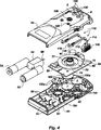
図4は、ベース筐体およびそれに含まれる構成要素の分解図である。
図5は、本発明のポンプのカセットの下方斜視図である。
図6は、カセットの上方分解図である。
図7は、カセットの下方分解図である。
図8は、ベース筐体に装着したカセットの側断面図で、種々の構成要素を示す。
図9Aおよび図9Bは、本発明のポンプの側断面図で、それぞれ開位置および閉一にある流量制御弁を示す。
図10Aから図10Eは、本発明に使用するのに適したフェース駆動ギアの例証的実施例の様々な図を示す。
図11Aおよび図11Bは、本発明でモータがポンプを作動させる駆動ハブと被動ハブの斜視図である。
図12は、本発明のモータ駆動シャフトおよびピニオン・ギア、およびフェース駆動ギアの部分側面図である。
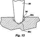
図13は、本発明に使用するフェース・ギアのスピンドルと支持ギア・カップの部分側断面図でる。
図14は、本発明に使用する例証的な毛管ラビリンス・シールの部分側断面図である。
図15は、本発明のピストン括約筋シールの部分側断面図である。
図16は、本発明の流路、ポンプ、弁、圧力センサおよびフィルタの略図である。
図面の詳細な説明
本発明を簡単に理解し、説明するために、図面類で、同様の部品または構成部品は、図面ごとに同様の番号で特定する。
図1は、電気モータ、バッテリ電源およびポンピング動作を制御するプログラム可能なマイクロプロセッサなど、本発明のポンプ・ドライバ構成要素が配置されたベース筐体4を有する、マイクロプロセッサ制御の歩行容量ポンプの、一つの例証的な実施例の上方斜視図である。ベース筐体4にはカセット8が着脱可能な状態で装着され、これにはポンプ機構と、患者に導入する流体をポンピングする流路と、流体の流れを制御する弁とが含まれる。送込管12がカセット8に結合されて、ポンピング機構の動作の結果、流体を源からカセットの流路へと送り、排出管16もカセットに結合されて、流体を流路から目的へと送る。ベース筐体4の側部には、患者がプログラム可能なマイクロプロセッサを起動することができる実行/停止スイッチ20が装着されている。
カセット8は、1対の装着クリップ24(図5も参照)によってベース筐体4の所定の位置に保持され、これは、カセット8をベース筐体4上の所定に位置に押し込むと外側に撓む。特に、装着クリップ24が外側に撓むと、クリップの橋部にあるタブ24a(図5)が、ベース筐体4の上壁4aにある窪み28の側部に形成されたサイド・スロット6内に延びる。カセット8を解放するには、装着クリップ24を内側に押してタブ24aを内側に撓ませ、それをスロット6から引き抜く。これでカセット8を取り外すことができる。
図2は、カセットを外して、ベース筐体の上壁4aに形成されたカセットを受ける窪み28を露出させた、ベース筐体4の上方斜視図である。ベース筐体4の上壁4aにある開口部を通して、圧力センサ・ボタン32aおよび32b(以下で述べる)、フェース駆動ギア72(これも以下で述べる)、および弁アクチュエータ・レバー・ピン40が露出し、ピンは以下で説明するように、カセット内に形成された流路に配置された弁を選択的に開閉して流体を流したり、流れを防止したりする。
図3は、筐体の下壁4bを通って露出した4つの回転式ノブ44a、44b、44cおよび44dを示す、ベース筐体4の底部の斜視図である。ノブ44aから44dの頂部は、下壁4bとほぼ面一で、したがって衣類または他の品目がノブに引っかからず、したがってノブは衝突などによって不注意に動くことがない。ノブ44aから44dの頂部表面には、矢印の形状の窪みが形成され、それに硬貨、爪、ドライバまたは他の道具を挿入して、ノブを所望の位置に回転する。ノブは、ベース筐体4に含まれたプログラム可能なマイクロプロセッサの「プログラム」に使用し、ノブのパラメータ設定に従ってポンプを操作する。つまり、各ノブの回転または角度位置は、ある期間の流量、投与数またはポンプ・サイクル、総投与時間、ポンピングされる流体の総量など、ポンプの特定の作動パラメータを確立する。
ノブの設定は、種々の方法でプログラム可能なマイクロプロセッサに連絡することができ、例えば金属の導電ワイパーをノブの下側に設けて、ベース筐体4に含まれたプリント回路板94(図4)の銅のパターンに押しつけ、プログラム可能なマイクロプロセッサが、銅のパターン上のワイパーの位置から2進コード化した信号またはビットを読めるようにする。
ノブ44a、44b、44cおよび44dの設定は、窪みの矢印が指す方向によって選択されたパラメータを、見えるように表示することも理解される。ノブの周囲に配置されたラベルは、ノブの様々な回転位置のパラメータ値を特定することができる。
次に図4を参照すると、上壁4aおよび下壁4bを含むベース筐体4の上方分解図が図示されている。プログラム可能なマイクロプロセッサ59と、ポンプを作動させるモータとを作動させるための電源であるバッテリ54および58を受け、これを保持するブラケット50が、下壁4bに形成される。小型電気モータ64を受け、これを保持するために、下壁4bにはブラケット60も形成される。モータ駆動シヤフト68(およびピニオン・ギア)がモータ64の前方に延在して、フェース駆動ギア72と嵌合し、モータ64を作動するとこれを回転する。
図12は、ローラ延長部78を伴うピニオン・ギア76を端部に装着したモータ駆動シャフト68の一部の部分断面図を示す。ピニオン・ギアの歯は、図12に示すように、フェース駆動ギア72の縁に形成されて軸方向に延在するギアの歯80と噛み合う。フェース・ギアの歯80の内部には環状ビード84が形成されて、フェース駆動ギア72の円周方向に延在し、その上を、モータ駆動シャフト68が回転するにつれてローラ78が転がり、したがってピニオン・ギアを回転してフェース駆動ギアを回転させる。ローラ78と環状ビード84との接触により、ピニオン・ギアの歯76はフェース・ギアの歯80から特定の距離を維持し、したがって2つのギア間の摩擦が減少し、ノイズが軽減される。摩擦が減少すると、エネルギー消費量も減少する。(ベース筐体全体を示す図で、フェース駆動ギア72がピニオン・ギア76の頂部に図示されていることに留意されたい。)
フェース駆動ギア72は、図10Aから図10Eでさらに詳細に図示されている。ギア72はディスク82を含み、図10Dおよび図10Eに示すように、その外縁の下側に歯80が形成されている。前述したように、環状ビード84が歯80のすぐ内側にある(しかし、外側にあってもよい)。中心窪み86がディスク82の下側に形成され、スピンドル88が窪み86から下方向に延在して(図10C)概ね球形の先端88aで終了する。スピンドル88は、ベース筐体4の下壁4bに配置されたベアリング・カップ90(図4)内で、フェース駆動ギア72を回転式に支持する。特に、フェース駆動ギア72のスピンドル88は、回路板94の開口部を通ってベアリング・カップ90へと延在し、これによってフェース駆動ギアが回転できるようにする。
図13は、ベアリング・カップ90内に配置されたスピンドル88の下端と先端88aの側断面図を示す。ベアリング・カップ90の側壁90aは、逆転した円錐の形状で、したがって球形の先端88aと側壁90aとの接触面は小さく、これはフェース駆動ギア72の回転時の摩擦を減少させ、したがってポンプ作動時の動力消費量を減少させる。フェース駆動ギア72の他の特徴を後に検討する。
次に図4に戻ると、4つのプログラミング・ディスク100が図示され、それぞれが、ノブを回転すると回転するようにプログラミング・ノブに結合され、したがって回路板94の下側の電気接点と様々な電気接点パターンを生成することができる。これらの電気接点は、ディスク100の電気接点100aが様々な接点に接触すると、プログラミング・ノブの様々な設定値がマイクロプロセッサ59によって検出されるように配置される。
回路板94は、ベース筐体4の下壁4bに装着され、既に示したように、ポンプの作動を制御するプログラム可能なマイクロプロセッサ59は、マイクロプロセッサと信号をやりとりする他の回路類と同様に、回路板に装着される。
フェース駆動ギア72の上表面には、カム・トラック74(図4、図10Aおよび図10B参照)が形成され、その上に1対の弁アクチュエータ・レバー110が載り、これに従う。各レバー110は、細長いビーム112、ビームの一方端にほぼ直角に配置されたピボット軸114、ビーム112の下表面の下に回転式に装着されて突き出し、カム・トラック74に載ってこれに従うカム従動ローラ116、およびビーム112の軸114の位置から反対の端部から上方向に突き出し、ベース筐体の上壁4aに形成された開口部120を通って延在するレバー・ピン112を含む。弁起動レバー110の構成と配置は、図9Aおよび図9Bの側面図でも見ることができる。フェース駆動ギア72が回転するにつれ、レバー110はフェース・ギアが1回転するたびに1回、上方向に交互に旋回し、以下で述べるように入口弁と出口弁を開く。
フェース駆動ギア72の上側には駆動ハブ75も配置され、これは毛管ラビリンス・シール77に囲まれる。駆動ハブ75は、ポンプの駆動に使用するクランク・シャフトと結合された対応の被動ハブと対合するよう設計される。駆動ハブ75の詳細な構成は図11Aに示され、被動ハブ73は図11Bに示される。ハブは両方とも駆動突起75aおよび73aを含み、対合するハブ上の駆動突起を嵌合させ、回転状態で駆動する。図11Bのハブ73は、逆さまにして、図11Aのハブ75の頂部に配置された状態で見ることができる。この構成で、ハブ75を上から見て反時計回りに回転すると、ハブ73が同様にその方向に回転することが明白である。図11Aのハブ75は、唯一の角度位置で、つまりハブ75の駆動突起75aがハブ73の駆動突起73aと嵌合する時に、図11Bのハブ73と嵌合し、したがって2つの駆動ハブは、作動位置にある場合は、常に互いに対して同じ相対的角度位置にあることに留意されたい。
毛管ラビリンス・シール77は、図10A、図10Bおよび図14にも詳細に図示され、複数の同心円の環状壁77aを含み、これは、フェース駆動ギア72をベース筐体4に設置すると、ベース筐体4の下壁4aの下側に形成された相補的な環状壁4c(図14)と環状に交互配置される。このような毛管ラビリンス・シール77とベース筐体4の上壁4aの下面にある相補的環状壁4cとの交互配置または噛み合いは、図8にも図示されている。毛管ラビリンス・シール77の目的は、カセット8からベース筐体へのアクセスが必要な位置で、水または他の流体がベース筐体4の内部に侵入するのを防止することである。本発明の毛管ラビリンス・シール77があると、液体は狭い「毛管トラップ」77b(図14)に引き込まれ、毛管ラビリンス壁77aとベース筐体の環状壁4cとの間のギャップによって形成されたこれより大きい「毛管中断部」または溜め77cによって、これらトラップから出るのが防止される。したがって、毛管トラップ77bにあるいかなる液体も、これらのトラップに留まる傾向がある。というのは、毛管中断部または溜め77cの毛管引力に対して、その毛管作用の方がはるかに大きいからである。毛管トラップ77bを通り抜ける液体があっても、それは毛管中断部または溜め領域77cを満たし、それ以上は進まない。
再び図4を参照すると、ベース筐体に形成された、圧力過剰/不足センサ・ボタン134(以下で述べる)と呼ばれるものを受ける2つの開口部130が図示されている。最後に、フェース駆動ギア72のハブ75を受けて、これへのアクセスを提供する開口部138が上壁4aに形成され、被動ハブとカセット8に配置されたクランク・シャフトを嵌合させる。
図5、図6および図7は、それぞれ下方斜視図、上方斜視分解図、および下方斜視分解図でカセット8を示す。カセット8は、頂部カバー200、主本体204および底部カバー297で構成される。本体204の下側および底部カバー108の上の一部に流路システム212(図7)が形成され、入口216(図6)を通る流体を受けて、出口220(図5および図7)へとポンピングする。
カセット8は、本体204の上側に装着されたポンプ機構224と、流路システム212を通る流体の流れを制御する弁システム228と、圧力過剰および不足センサ232(図5および図7)と、空気排除および流体フィルタ室236(図6)も含む。ポンプ機構224はクランク224aを含み、そのクランク・シャフト224bは本体204の開口部240および底部カバー208の開口部242を通って延在して、図5で最もよく分かるように、底部カバーの下にある程度の距離突き出す。前述した被動ハブ73は、クランク・シャフト224bの端部に配置される(図5)。前述したように、被動ハブ73は、フェース駆動ギア72に含まれた駆動ハブ75(図4)と嵌合し、それはピニオン・ギア76(図12)およびモータ74(図4)によって駆動されて回転する。したがって、クランク224aはモータの作動時は常に回転するようになっている。
ポンプ機構224は、接続棒224cおよびピストン224dも含む。クランク224aは、旋回する状態で接続棒224cの一方端に結合され、接続棒の他方端は、旋回する状態でピストン224dの接続ニップル224e(図6および図7)に結合される。ピストン224dは、摺動可能な状態で口250を通ってポンピング室254に入るよう配置され、ピストン・ガイド258内に摺動可能な状態で保持される(図6)。ピストン括約筋シール260は、図6および図7ではピストン224dの周囲に配置されるよう図示されているが、シールは保持空洞264の口250の前に配置することもある。シール260はポンピング動作中に流体が室254から漏出するのを防止し、しかも非常に抵抗が非常に少なく、したがってポンピング中のエネルギー消費量が最小限になる。
図15は、保持空洞264に配置されたピストン括約筋シール260の側断面図を示し、シールは前方に延在する枝260aと、後方に延在する枝260bとを含み、両方ともピストン224dを囲んで、これと接触する。クランク224aを回転して、接続棒224cがピストン224dを動かすようにすると、ピストンは往復してポンピング室254を出入りし、カセット8を通して流体をポンピングする。
弁システム228は、図6および図7では1対の弁レバー228aおよび228bを含むよう図示され、それぞれがビーム228c、ピボット軸228dおよび弁閉鎖ニップル228eを含む(図6)。弁レバー228aおよび228bは、底部カバー208に旋回状態で装着されて、スロット270に嵌合する(図6)。板ばね228fが、底部カバー208の下側に形成されたスロット274に圧入される(図5および図7)。ばね228fは、弁閉鎖ニップル228eの位置のすぐ下でビーム228の下側に押しつけられ、ニップルを上方向に押しやり、個々の弁を常時閉とする(以下で述べる)。弁を開くために、ニップル228eの位置と反対側のビーム228cの端部は、弁起動レバー110の対応するレバー・ピン118によって、(ニップルを下方向に旋回させるよう)上方向に移動する(図4)。レバー・ピン118は、底部カバー208の対応する開口部278を通って延在し、レバー228aおよび228bと接触して、弁を開く。
圧力過剰および不足センサ232は開口部232aおよび232bを含み、これを通って圧力センサ・ボタン134(図4および図8)が延在してガスケットまたは膜282と接触し、流体がそこを流れてカセット8に入り、カセット8から出る。カセット8の出口220より下流の圧力が増加して、例えば管の閉塞を示すと、膜282はボタン134の一方に向かって膨らみ、そのボタンが動いて可動接触ばねを押し、回路板94上の静止接点と電気的に接触して、プログラム可能なマイクロプロセッサ59に、「圧力過剰状態」が出口の下流に存在することを示す。これで、マイクロプロセッサ59は、アラーム95(図4)を鳴らすか、ポンピングを停止する、あるいは両方をすることができる。例えば、閉塞がカセット8の出口216より上流の管で発生し、ポンプが作動していたか、作動していると、入口付近の流路で真空が発生し、膜282の別の部分がさらに流路へと引っ張られ(膨らむ反対)、対応するボタン134がわずかに流路に向かって動き、回路板94上の回路およびプログラム可能なマイクロプロセッサ59に対して、上方で閉塞が発生したことを示す。アラーム95は、圧力可能の感知時と同様に、鳴るかポンピングを停止する、あるいはその両方をすることができる。これについては全て、他の図の検討の時にさらに説明する。
空気排除および流体フィルタ室236(図6)は、カセット8の流路を流れる流体から空気を排除し、流体を濾過して汚染物質などを除去する。これについては、以下で検討する。
膜ガスケット282は、カセット8の本体204下側の有意の部分を覆って、カセットを通って延在する流路を規定する(その一方側を形成する)よう配置される。ガスケット282によって、流量制御弁および圧力過剰および不足センサも作動することができ、回転するクランク・シャフト224bの周囲に無菌シール309も設けることができる。
図8はベース筐体4の断面図で、モータ64、モータの駆動シャフト68に装着されたピニオン・ギア76、および歯80が前述したようにピニオン・ギアの歯76と噛み合うフェース駆動ギア72を示す。フェース駆動ギア72のスピンドル88は、ベアリング・カップ90内に回転状態で支持される。圧力センサ・ボタン134が開口部130内に配置されて図示され、ボタンの上端が膜282とほぼ接触している。膜282に、それと接触する流体の過剰圧力がかかると、膜が変形してボタン134に押しつけられて、ボタンが接触ばね300に押し当てられ、したがって接触ばね自体が撓んでプログラム可能なマイクロプロセッサ59に、出口の下流で圧力過剰状態が検出されたという信号を送る。接触ばね300が十分撓むと、回路板94上の静止接点と電気的に接触し、この電気的接触がマイクロプロセッサ59に検出される。圧力不足センサは同様の方法で作動するが、ただしばね308(図7参照)が膜282の上に配置され、これによって膜が押し下げられて異なる圧力センサ・ボタンに当たり、したがって接触ばね300の異なる部分に力を加える。次に、圧力不足状態が入口の上流で発生すると、膜282がブタンから引き離され、(ポンピング作用によって生じた負圧のせいで)圧力不足ばね308を圧迫し、このためボタンが接触ばねへの力を解除する。この状態が検出され、プログラム可能なマイクロプロセッサが、圧力不足状態が、発生していることを警告する。
接触ばね300の圧力不足部分は、通常、カセット8がベース筐体4にクリップ留めされている場合は静止接点304と接触している。カセット8をベース筐体にクリップ留めすると、圧力不足バネ308(図7)が膜282を外方向に押し、ボタン134の1つに押し当てる。このボタンは接触ばね300の圧力不足部分を押下し、したがってこれは静止接点304との電気的接続を中断する。次に、カセット8を取り外すか、上流で圧力不足状態が発生すると、接触ばね300のこの圧力不足部分が元の位置に戻ることができ、静止接点304と接触する。この接点の閉鎖がマイクロプロセッサ59によって感知されると、これはアラーム95を鳴らすか、他の適切な措置をとる。
電気接触ばね300の圧力過剰部分は、通常は静止接点304と接触していない。センサの下流が圧力過剰状態になると、既に説明したように、膜282が外側に膨らんで、ボタン134を押して動かし、ボタンが電気接触ばね300の圧力過剰部分を撓ます。ばね300は、十分撓むと静止接点304と接触し、この電気的接触がマイクロプロセッサ59に感知され、これは適切な措置をとることができる。
図8は、1回転ごとにプリント回路板94上の接点から接触ばね315を離す、フェース駆動ギアのスピンドル88の一方側に形成されたローブ88bも示す。モータの接触ばね315が撓むと、そうさせたモータ64およびマイクロプロセッサ59への電力供給線を遮断する。したがって、フェース駆動ギア72が1回転するごとに、モータが自動的に切れる。これで、プログラム可能なマイクロプロセッサ89が、マイクロプロセッサに「プログラムされた」投与スケジュールに応じて、(モータの接触ばねの開接続を迂回することによって)次の投与のためにモータを始動する。
図9Aおよび図9Bは、それぞれ流量制御弁の開放時および流量制御弁の閉鎖時のベース筐体4およびカセット8の側断面図を示す。ここで図9Aを参照すると、一方の弁アクチュエータ・レバー110が、(カム・トラック上で上方向に動くカム・ローラ116の結果)上方向に旋回して、一方の弁レバー228の後端を押し上げ、弁閉鎖ニップル228eを押し下げて膜282を解放し、したがって流体を運ぶ流路310が開く。
フェース駆動ギア(図示せず)が回転し続けるにつれ、駆動ギア上に形成されたカム・トラックが下方向に湾曲し、したがって、カム・ローラ116は図9Bに示すように下方向に動作することができる。したがって、弁アクチュエータ・レバー110のレバー・ピン118が下方向に動作して弁レバー228を解放し、これによって弁レバーの戻りばね228fは弁閉鎖ニップル228eを押し上げることができ、膜282を変形させ、流路310の通路に押し込んで流体の流れを遮断する。前述した方法で、膜282は交互に変形して流体の流れを遮断したり、解放して流体が流れるようにし、流体は弁の通常位置で遮断される。言うまでもなく、2つの弁を使用し、1つは流路の入口付近、1つは出口付近にして、流体の流れを制御する。
次に図9Bを参照すると、親水性フィルタ膜320と、外側への開口部328を覆う疎水性膜324とを含む空気排除および流体フィルタ室236の断面図が図示されている。流路310を流れる流体は、室236に流れ込み、疎水性膜324によって流体中の空気は膜を通って筐体の外部に拡散できるが、流体は通過できない。室236の他方側には、2つの目的を果たす親水性膜320がある。つまり流体は通過させるが空気は通過させず、また流体を濾過するのである。例証的に、親水性膜の孔サイズは1.2ミクロンで、膜の表面積は4.0平方センチメートルである。
図16は、カセットを通って延在する流路212を含む、本発明の主要構成要素の一部の概略図で、流路は入口216および出口220を有する。圧力不足センサ232aは、(例えば上流の閉塞によって)流路のその位置に吸引が発生した場合に、マイクロプロセッサ59に信号を送るため流路に配置されるよう図示されている。流体は、圧力不足センサ232aから、モータ64の力でフェース駆動ギア72(図16には図示せず)が回転することによって前述したように機械的に開閉する入口弁400へと流れる。ポンプ機構224は交互に、流体を入口弁400からポンプ室254へと吸い込み、次に流体をポンプ室から吸い出して、出口弁404を通し、これはフェース駆動ギア72の回転によって開いている。そこから、流体は空気排除および流体フィルタ室236を通って、圧力過剰センサ232bへと流れる。過剰圧力が発生すると、前述したようにマイクロプロセッサ59に信号が送られる。次に、流体は出口220から流れ出す。マイクロプロセッサ59は、モトローラ(Motorola)製のMC 68HC05モデルなど、任意の適切なタイプのマイクロプロセッサでよい。
上記の配置構成は、本発明の原理の応用の例証に過ぎないことを理解されたい。本発明の精神および範囲から逸脱することなく、当業者には無数の変形および代替配置構成が考案でき、添付の請求の範囲は、このような変形および配置構成を対象とするものとする。 Background of the Invention
This application is a continuation-in-part of Application No. 08 / 157,693 entitled VOLUMETRIC PUMP / VALVE filed on November 23, 1993.
The present invention relates to a lightweight and inexpensive ambulatory capacity pump suitable for various applications including medical systems such as intravenous (IV) treatment systems.
Intravenous administration of fluids to patients is particularly acute, administering life support nutrients to patients whose gastrointestinal tract cannot function normally due to disease or injury, administering antibiotics to treat various serious infections Or, well-known medical procedures, such as administering analgesics to patients suffering from chronic pain, administering chemotherapeutic drugs to the treatment of cancer patients, and the like.
Intravenous administration of drugs often involves connecting to a so-called IV dosing set, including, for example, a bottle of fluid to be administered, a set of sterile plastic tubes, usually placed upside down, and a pump that pumps fluid from the bottle through the IV set to the patient. It is necessary to use an IV pump built in it. Other mechanisms can also be included to manually stop fluid flow to the IV supply tube and possibly some monitoring device.
There are two basic types of current IV pumps. An electronic pump and a disposable non-electronic pump. Electronic pumps are greatly miniaturized and actually contain some disposable components, but they are still very expensive, have to be frequently maintained and used continuously, for example to do it yourself When it is desirable, it may be difficult for an amateur to operate.
A disposable non-electric pump is usually composed of a small elastic bag in a hard envelope, and the bag is filled with pressurized IV solution. Due to the pressure generated by the contraction of the elastic bag, the IV solution enters the patient's vein through the fixed orifice at a constant flow rate. These pumps are much cheaper than electronic pumps and do not require maintenance (because they are discarded every time they are used), but their drawbacks are no monitoring, no choice of various flow rates, limited fluid capacity And is still relatively expensive for disposable products.
Summary of the Invention
It is an object of the present invention to provide a new and improved intravenous pump, particularly suitable for use in IV administration sets, other medical and non-medical systems, and the like.
It is a further object of the present invention to provide such a pump that is simple to manufacture and uses low cost components.
It is also an object of the present invention to provide a pump that is efficient and reliable.
It is an additional object of the present invention to provide a pump that can be easily miniaturized.
It is another object of the present invention to provide a pump that is ambulatory, low cost and therefore disposable.
It is a further object of the present invention to provide a pump with low friction components so that it can operate with low energy consumption.
According to one aspect of the present invention, it is yet another object of the present invention to provide a pump that can easily change flow rate or pumping rate, total operating time, time interval between doses, and the like.
According to another aspect of the present invention, it is also an object of the present invention to provide a pump in which operating parameters are controlled by a microprocessor.
These and other objects of the present invention are well understood in a particular illustrative embodiment of a walking volume pump that includes a housing and defines a flow path having an inlet for receiving fluid and an outlet for discharging fluid therein. The Within the housing is a pump operable to pump fluid through the flow path, a motor operating the pump in response to a control signal, and selectively supplying the control signal to the motor to operate the motor; A programmable controller is also arranged to pump the fluid intermittently or continuously.
According to one aspect of the present invention, the programmable controller is provided with a rotary knob that is exposed and accessible through the housing, which, when rotated to a selected position, sets the operating parameters of the pump. As well as establishing, display to see which parameter is selected.
In another aspect of the present invention, the casing has a base casing in which a motor and a programmable controller are disposed, a case in which a flow path is defined and a pump is disposed, and a clip mechanism that can clip the case to the base casing. Including. The motor includes a drive gear that is exposed through the wall of the base housing, and the pump includes a drive hub, which is matable with and driven by the drive gear when the case is clipped to the base housing. .
According to yet another aspect of the invention, the pump uses a simple circumferential polymer seal or sphincter seal to hold the pumped fluid and prevent its loss or leakage.
[Brief description of the drawings]
The above and other objects, features and advantages of the present invention will become apparent upon consideration of the following detailed description presented in combination with the accompanying drawings.
FIG. 1 is a top perspective view of a walking capacity pump made in accordance with the principles of the present invention.
FIG. 2 is an upper perspective view of the base casing of the pump of the present invention.
FIG. 3 is a lower perspective view of the base casing.
FIG. 4 is an exploded view of the base housing and the components included therein.
FIG. 5 is a lower perspective view of the cassette of the pump of the present invention.
FIG. 6 is an upper exploded view of the cassette.
FIG. 7 is a lower exploded view of the cassette.
FIG. 8 is a cross-sectional side view of a cassette mounted on a base housing, showing various components.
9A and 9B are side cross-sectional views of the pump of the present invention showing the flow control valve in an open position and closed, respectively.
10A through 10E show various views of an exemplary embodiment of a face drive gear suitable for use with the present invention.
11A and 11B are perspective views of a drive hub and a driven hub in which the motor operates the pump in the present invention.
FIG. 12 is a partial side view of the motor drive shaft, pinion gear, and face drive gear of the present invention.
FIG. 13 is a partial sectional side view of a face gear spindle and support gear cup used in the present invention.
FIG. 14 is a partial cross-sectional side view of an exemplary capillary labyrinth seal for use with the present invention.
FIG. 15 is a partial cross-sectional side view of the piston sphincter seal of the present invention.
FIG. 16 is a schematic diagram of the flow path, pump, valve, pressure sensor and filter of the present invention.
Detailed description of the drawings
For a simple understanding and description of the present invention, like parts or components in the drawings are identified with like numbers in each drawing.
FIG. 1 shows a microprocessor controlled walking capacity pump having a base housing 4 in which the pump driver components of the present invention are arranged, such as an electric motor, a battery power source and a programmable microprocessor for controlling the pumping operation. 1 is a top perspective view of one illustrative embodiment. FIG. A cassette 8 is detachably mounted on the base housing 4 and includes a pump mechanism, a flow path for pumping fluid to be introduced into a patient, and a valve for controlling the flow of fluid. The
The cassette 8 is held at a predetermined position of the base housing 4 by a pair of mounting clips 24 (see also FIG. 5), which flexes outward when the cassette 8 is pushed into a predetermined position on the base housing 4. Mu In particular, when the
FIG. 2 is an upper perspective view of the base housing 4 with the cassette removed and the
FIG. 3 is a perspective view of the bottom of the base housing 4 showing the four
The setting of the knob can be communicated to a programmable microprocessor in various ways, for example, a metal conductive wiper is provided on the underside of the knob to provide a printed circuit board 94 (FIG. 4) contained in the base housing 4. ) To allow the programmable microprocessor to read the binary encoded signal or bit from the position of the wiper on the copper pattern.
It is also understood that the setting of the
Referring now to FIG. 4, an upper exploded view of the base housing 4 including the
FIG. 12 shows a partial cross-sectional view of a portion of a
The
FIG. 13 shows a cross-sectional side view of the lower end and
Returning now to FIG. 4, four
The
A cam track 74 (see FIGS. 4, 10A and 10B) is formed on the upper surface of the
A
The
Referring again to FIG. 4, two
5, 6 and 7 show the cassette 8 in a lower perspective view, an upper perspective exploded view and a lower perspective exploded view, respectively. The cassette 8 includes a
Cassette 8 includes a
The
FIG. 15 shows a side cross-sectional view of the
The
Overpressure and underpressure
The air exclusion and fluid filter chamber 236 (FIG. 6) excludes air from the fluid flowing through the flow path of the cassette 8 and filters the fluid to remove contaminants and the like. This will be discussed below.
The
FIG. 8 is a cross-sectional view of the base housing 4. The
The under-pressure portion of the
The overpressure portion of the
FIG. 8 also shows a
9A and 9B show side sectional views of the base housing 4 and the cassette 8 when the flow control valve is opened and when the flow control valve is closed, respectively. Referring now to FIG. 9A, one
As the face drive gear (not shown) continues to rotate, the cam track formed on the drive gear curves downward, so that the
Referring now to FIG. 9B, a cross-sectional view of an air exclusion and
FIG. 16 is a schematic diagram of a portion of the main components of the present invention, including a
It should be understood that the above arrangement is merely illustrative of the application of the principles of the present invention. Numerous variations and alternative arrangements can be devised by those skilled in the art without departing from the spirit and scope of the invention, and the appended claims are intended to cover such variations and arrangements.
Claims (29)
ベース筐体およびケースを含む筐体と、
前記ケースに配置され、流体を受ける入口と流体を放出する出口とを有する流路手段と、
前記ケースに配置され、流路手段を通って流体を送給するように計測された容量の流体をポンピングする往復作動可能な容量ポンプ手段と、
流路手段に結合されるポンプ室であって、該ポンプ室に流体を流入させる第1開口と、該ポンプ室から流体を流出させる第2開口とポンプ手段を受け入れる第3開口とを有するポンプ室と、
前記ベース筐体に配置され、該ベース筐体の下壁にある開口部を通して露出し、制御信号に応じてポンプ手段を操作するモータ手段と、
前記ベース筐体に配置され、モータ手段に制御信号を選択的に供給し、モータ手段を作動させかつ送給パラメータの一つ又は複数に変化させる手段となるプログラム可能な制御手段とを備え、
前記ポンプ手段が、前記駆動手段と嵌合可能で、ケースがベース筐体にクリップ留めされると、該駆動手段によって駆動される被動ハブを含み、そして
前記ケースが、
下側に少なくとも流路手段の一部が形成され、ポンプ手段が配置された本体と、
本体の上側に配置された頂部カバーと、
本体の下側に配置された底部カバーと、
少なくとも本体の一部の上、および本体と底部カバーとの間に配置され、流路手段の少なくとも一部の一方側を形成するガスケット膜とを含み、
前記ケースを前記ベース筐体にクリップ留めできるクリップ手段を備えたことを特徴とする装置。 A walking capacity pump device,
A housing including a base housing and a case;
Channel means disposed in the case and having an inlet for receiving fluid and an outlet for discharging fluid;
A reciprocally operable volume pump means disposed in the case and pumping a volume of fluid measured to deliver fluid through the flow path means;
A pump chamber coupled to the flow path means, having a first opening for allowing fluid to flow into the pump chamber, a second opening for allowing fluid to flow out from the pump chamber, and a third opening for receiving the pump means When,
Motor means disposed in the base casing, exposed through an opening in the lower wall of the base casing, and operating the pump means in response to a control signal;
Programmable control means disposed on the base housing and serving as means for selectively supplying control signals to the motor means, actuating the motor means and changing to one or more of the feed parameters,
The pump means includes a driven hub that is matable with the drive means and is driven by the drive means when the case is clipped to the base housing; and
The case is
A main body in which at least a part of the channel means is formed on the lower side and the pump means is disposed;
A top cover disposed on the upper side of the body;
A bottom cover located on the underside of the body,
A gasket membrane disposed on at least a portion of the body and between the body and the bottom cover and forming at least one side of the flow channel means;
An apparatus comprising clip means for clipping the case to the base housing .
流路手段の少なくとも一部の一方側に形成され、流路手段の当該部分へと変形して流体の流れを遮断することができる弾性膜と、
膜を流路手段内へと変形して流体の流れを遮断するよう動作でき、流路手段から離れて膜を解放し、流体が流れることができるように動作可能なニップル手段と、
通常はニップル手段が膜を変形するように偏寄されたばね手段と、
ニップル手段を選択的に流路手段から離れるよう動作させ、流体が流れることができるようにする手段とを備える、請求項9に記載の装置。The inlet and outlet valve means are each
An elastic membrane that is formed on one side of at least a portion of the flow path means and can be deformed into that portion of the flow path means to block the flow of fluid;
Nipple means operable to deform the membrane into the flow path means to block the flow of fluid, release the film away from the flow path means and allow fluid to flow; and
Spring means normally biased so that the nipple means deforms the membrane;
10. An apparatus according to claim 9 , comprising means for selectively moving the nipple means away from the flow path means to allow fluid to flow.
第1端部および第2端部を有し、第1端部から間隔をあけた軸を中心に旋回するように装着される細長いレバーと、
レバーからほぼ直角に第1端部から延在して、レバーが第1位置へと旋回すると膜に接触してこれを変形し、レバーが第2位置へと旋回すると膜を解放するニップルとを備える、請求項10に記載の装置。The nipple means comprises:
An elongate lever having a first end and a second end and mounted to pivot about an axis spaced from the first end;
A nipple extending from the first end at a substantially right angle from the lever, contacting and deforming the membrane when the lever pivots to the first position and releasing the membrane when the lever pivots to the second position; The apparatus of claim 10 , comprising:
起動レバーから延在し、起動レバーが旋回すると、細長いレバーの第2端部に接触して、これを第2位置へと移動させる押し手段と、
起動レバー上に配置されてカム・トラックに載り、その上で動いて起動レバーを旋回させるカム従動手段とを備える、請求項13に記載の装置。The motor means includes gear means having a cam track defined thereon, the cam track operating during operation of the motor means, the operating means being spaced from one end by a shaft. An activation lever mounted to pivot to the center;
Push means extending from the activation lever and contacting the second end of the elongated lever when the activation lever pivots to move it to a second position;
14. An apparatus as claimed in claim 13 , comprising cam follower disposed on the activation lever, resting on the cam track, and moving thereon to pivot the activation lever.
カム・トラックを回転させるギア手段の回転中心である軸手段を含み、前記軸手段が、ギア手段が回転するにつれ支持体上に載る下端部を含み、さらに、
前記軸手段の下端部を受け、これを保持する支持カップ・ベアリングを含む、請求項14に記載の装置。The gear means
Shaft means that is the center of rotation of the gear means for rotating the cam track, the shaft means comprising a lower end that rests on the support as the gear means rotates;
15. A device according to claim 14 , comprising a support cup bearing for receiving and holding the lower end of the shaft means.
ポンプ室の第3開口部に配置されて往復し、ポンプ室を出入りして流体を送給するピストン手段と、
第3開口部の上およびピストン手段の周囲に配置されて、流体がポンプ室から第3開口部を通って漏出するのを防止する括約筋シールとを備える、請求項1に記載の装置。The pump means
Piston means disposed in the third opening of the pump chamber to reciprocate, and to enter and exit the pump chamber to feed fluid;
2. A device according to claim 1, comprising a sphincter seal disposed over the third opening and around the piston means to prevent fluid from leaking out of the pump chamber through the third opening.
モータ手段に結合されて、モータ手段が作動すると回転するクランク手段と、
クランク手段とピストン手段との間に旋回する状態で結合され、クランク手段が回転するとピストン手段を往復させる接続手段とを備える、請求項27に記載の装置。The pump means further
Crank means coupled to the motor means and rotating when the motor means is activated;
28. The apparatus of claim 27 , comprising a pivot means coupled between the crank means and the piston means for reciprocating the piston means as the crank means rotates.
Applications Claiming Priority (3)
| Application Number | Priority Date | Filing Date | Title |
|---|---|---|---|
| US08/643,472 US5807075A (en) | 1993-11-23 | 1996-05-06 | Disposable ambulatory microprocessor controlled volumetric pump |
| US08/643,472 | 1996-05-06 | ||
| PCT/US1997/007600 WO1997042410A1 (en) | 1996-05-06 | 1997-05-06 | Disposable ambulatory microprocessor controlled volumetric pump |
Related Child Applications (1)
| Application Number | Title | Priority Date | Filing Date |
|---|---|---|---|
| JP2006254519A Division JP2007021237A (en) | 1996-05-06 | 2006-09-20 | Disposable microprocessor-controlled moving capacity pump apparatus |
Publications (3)
| Publication Number | Publication Date |
|---|---|
| JP2000510722A JP2000510722A (en) | 2000-08-22 |
| JP2000510722A5 JP2000510722A5 (en) | 2004-10-28 |
| JP3927240B2 true JP3927240B2 (en) | 2007-06-06 |
Family
ID=24580968
Family Applications (2)
| Application Number | Title | Priority Date | Filing Date |
|---|---|---|---|
| JP54013297A Expired - Fee Related JP3927240B2 (en) | 1996-05-06 | 1997-05-06 | Disposable microprocessor controlled walking capacity pump |
| JP2006254519A Pending JP2007021237A (en) | 1996-05-06 | 2006-09-20 | Disposable microprocessor-controlled moving capacity pump apparatus |
Family Applications After (1)
| Application Number | Title | Priority Date | Filing Date |
|---|---|---|---|
| JP2006254519A Pending JP2007021237A (en) | 1996-05-06 | 2006-09-20 | Disposable microprocessor-controlled moving capacity pump apparatus |
Country Status (9)
| Country | Link |
|---|---|
| US (1) | US5807075A (en) |
| EP (1) | EP0897473B1 (en) |
| JP (2) | JP3927240B2 (en) |
| AT (1) | ATE281194T1 (en) |
| AU (1) | AU2828297A (en) |
| DE (1) | DE69731464T2 (en) |
| HK (1) | HK1019084A1 (en) |
| TW (1) | TW358032B (en) |
| WO (1) | WO1997042410A1 (en) |
Families Citing this family (119)
| Publication number | Priority date | Publication date | Assignee | Title |
|---|---|---|---|---|
| US20030069522A1 (en) | 1995-12-07 | 2003-04-10 | Jacobsen Stephen J. | Slotted medical device |
| US6077055A (en) * | 1998-12-03 | 2000-06-20 | Sims Deltec, Inc. | Pump system including cassette sensor and occlusion sensor |
| TR200002802T1 (en) * | 1999-02-01 | 2000-12-21 | Baxter International Inc. | Metered dose infusion pump and method. |
| US6497676B1 (en) | 2000-02-10 | 2002-12-24 | Baxter International | Method and apparatus for monitoring and controlling peritoneal dialysis therapy |
| WO2002068015A2 (en) * | 2001-02-22 | 2002-09-06 | Insulet Corporation | Modular infusion device and method |
| US20040034331A1 (en) * | 2001-02-23 | 2004-02-19 | Jason Toman | Integrated medication delivery system |
| JP4058498B2 (en) * | 2001-02-23 | 2008-03-12 | ストライカー コーポレイション | Integrated drug delivery system |
| US20030009208A1 (en) | 2001-07-05 | 2003-01-09 | Precision Vascular Systems, Inc. | Torqueable soft tip medical device and method of usage |
| US7153286B2 (en) | 2002-05-24 | 2006-12-26 | Baxter International Inc. | Automated dialysis system |
| US7175606B2 (en) | 2002-05-24 | 2007-02-13 | Baxter International Inc. | Disposable medical fluid unit having rigid frame |
| US6869538B2 (en) * | 2002-05-24 | 2005-03-22 | Baxter International, Inc. | Method and apparatus for controlling a medical fluid heater |
| JP2005533560A (en) | 2002-07-19 | 2005-11-10 | バクスター インターナショナル インコーポレイテッド | System and method for performing peritoneal dialysis |
| US7238164B2 (en) | 2002-07-19 | 2007-07-03 | Baxter International Inc. | Systems, methods and apparatuses for pumping cassette-based therapies |
| US7914467B2 (en) | 2002-07-25 | 2011-03-29 | Boston Scientific Scimed, Inc. | Tubular member having tapered transition for use in a medical device |
| CA2493013C (en) | 2002-07-25 | 2011-07-19 | Boston Scientific Limited | Medical device for navigation through anatomy and method of making same |
| US6893414B2 (en) * | 2002-08-12 | 2005-05-17 | Breg, Inc. | Integrated infusion and aspiration system and method |
| GB2408071B (en) * | 2002-08-17 | 2005-10-19 | Siemens Magnet Technology Ltd | Pressure relief valve for a helium gas compressor |
| US8377035B2 (en) | 2003-01-17 | 2013-02-19 | Boston Scientific Scimed, Inc. | Unbalanced reinforcement members for medical device |
| US7169118B2 (en) | 2003-02-26 | 2007-01-30 | Scimed Life Systems, Inc. | Elongate medical device with distal cap |
| US7001369B2 (en) | 2003-03-27 | 2006-02-21 | Scimed Life Systems, Inc. | Medical device |
| US7575564B2 (en) | 2003-10-28 | 2009-08-18 | Baxter International Inc. | Priming, integrity and head height methods and apparatuses for medical fluid systems |
| US8029454B2 (en) | 2003-11-05 | 2011-10-04 | Baxter International Inc. | High convection home hemodialysis/hemofiltration and sorbent system |
| US7824345B2 (en) | 2003-12-22 | 2010-11-02 | Boston Scientific Scimed, Inc. | Medical device with push force limiter |
| US7632242B2 (en) | 2004-12-09 | 2009-12-15 | Boston Scientific Scimed, Inc. | Catheter including a compliant balloon |
| DE102004063644A1 (en) * | 2004-12-31 | 2006-07-20 | Tecpharma Licensing Ag | Device for the dosed administration of a fluid product with torsion spring drive |
| US8147451B2 (en) * | 2005-02-11 | 2012-04-03 | Stryker Corporation | Reprogrammable fluid delivery system and method of use |
| JP2006280391A (en) * | 2005-03-31 | 2006-10-19 | Terumo Corp | Cassette for infusion pump with deaeration module and portable infusion pump used for the same |
| GB0515040D0 (en) * | 2005-07-21 | 2005-08-31 | Bristol Myers Squibb Co | Compression device for the limb |
| US9445784B2 (en) | 2005-09-22 | 2016-09-20 | Boston Scientific Scimed, Inc | Intravascular ultrasound catheter |
| US7850623B2 (en) | 2005-10-27 | 2010-12-14 | Boston Scientific Scimed, Inc. | Elongate medical device with continuous reinforcement member |
| US8177974B2 (en) | 2006-04-14 | 2012-05-15 | Emd Millipore Corporation | Disposable tangential flow filtration device holder |
| US7779625B2 (en) | 2006-05-11 | 2010-08-24 | Kalypto Medical, Inc. | Device and method for wound therapy |
| US7615036B2 (en) | 2006-05-11 | 2009-11-10 | Kalypto Medical, Inc. | Device and method for wound therapy |
| CA2663319A1 (en) | 2006-09-13 | 2008-03-20 | Boston Scientific Limited | Crossing guidewire |
| US9522221B2 (en) | 2006-11-09 | 2016-12-20 | Abbott Medical Optics Inc. | Fluidics cassette for ocular surgical system |
| US10959881B2 (en) | 2006-11-09 | 2021-03-30 | Johnson & Johnson Surgical Vision, Inc. | Fluidics cassette for ocular surgical system |
| US9295765B2 (en) | 2006-11-09 | 2016-03-29 | Abbott Medical Optics Inc. | Surgical fluidics cassette supporting multiple pumps |
| US8414534B2 (en) | 2006-11-09 | 2013-04-09 | Abbott Medical Optics Inc. | Holding tank devices, systems, and methods for surgical fluidics cassette |
| US8491528B2 (en) | 2006-11-09 | 2013-07-23 | Abbott Medical Optics Inc. | Critical alignment of fluidics cassettes |
| US8556914B2 (en) | 2006-12-15 | 2013-10-15 | Boston Scientific Scimed, Inc. | Medical device including structure for crossing an occlusion in a vessel |
| US10485699B2 (en) | 2007-05-24 | 2019-11-26 | Johnson & Johnson Surgical Vision, Inc. | Systems and methods for transverse phacoemulsification |
| US10363166B2 (en) | 2007-05-24 | 2019-07-30 | Johnson & Johnson Surgical Vision, Inc. | System and method for controlling a transverse phacoemulsification system using sensed data |
| US10596032B2 (en) | 2007-05-24 | 2020-03-24 | Johnson & Johnson Surgical Vision, Inc. | System and method for controlling a transverse phacoemulsification system with a footpedal |
| US8409114B2 (en) | 2007-08-02 | 2013-04-02 | Boston Scientific Scimed, Inc. | Composite elongate medical device including distal tubular member |
| US8105246B2 (en) | 2007-08-03 | 2012-01-31 | Boston Scientific Scimed, Inc. | Elongate medical device having enhanced torque and methods thereof |
| US8821477B2 (en) | 2007-08-06 | 2014-09-02 | Boston Scientific Scimed, Inc. | Alternative micromachined structures |
| US9808595B2 (en) | 2007-08-07 | 2017-11-07 | Boston Scientific Scimed, Inc | Microfabricated catheter with improved bonding structure |
| US10342701B2 (en) | 2007-08-13 | 2019-07-09 | Johnson & Johnson Surgical Vision, Inc. | Systems and methods for phacoemulsification with vacuum based pumps |
| US7841994B2 (en) | 2007-11-02 | 2010-11-30 | Boston Scientific Scimed, Inc. | Medical device for crossing an occlusion in a vessel |
| US8376961B2 (en) | 2008-04-07 | 2013-02-19 | Boston Scientific Scimed, Inc. | Micromachined composite guidewire structure with anisotropic bending properties |
| US8062513B2 (en) | 2008-07-09 | 2011-11-22 | Baxter International Inc. | Dialysis system and machine having therapy prescription recall |
| US9514283B2 (en) | 2008-07-09 | 2016-12-06 | Baxter International Inc. | Dialysis system having inventory management including online dextrose mixing |
| US7959598B2 (en) | 2008-08-20 | 2011-06-14 | Asante Solutions, Inc. | Infusion pump systems and methods |
| US8535243B2 (en) | 2008-09-10 | 2013-09-17 | Boston Scientific Scimed, Inc. | Medical devices and tapered tubular members for use in medical devices |
| US9795507B2 (en) | 2008-11-07 | 2017-10-24 | Abbott Medical Optics Inc. | Multifunction foot pedal |
| WO2010054142A1 (en) | 2008-11-07 | 2010-05-14 | Abbott Medical Optics Inc. | Controlling of multiple pumps |
| WO2010054145A1 (en) | 2008-11-07 | 2010-05-14 | Abbott Medical Optics Inc. | Surgical cassette apparatus |
| EP2376035B1 (en) | 2008-11-07 | 2016-12-14 | Abbott Medical Optics Inc. | Automatically switching different aspiration levels and/or pumps to an ocular probe |
| EP3195836B1 (en) | 2008-11-07 | 2019-09-18 | Johnson & Johnson Surgical Vision, Inc. | Automatically pulsing different aspiration levels to an ocular probe |
| CA2742977C (en) | 2008-11-07 | 2017-01-24 | Abbott Medical Optics Inc. | Adjustable foot pedal control for ophthalmic surgery |
| US10349925B2 (en) | 2008-11-07 | 2019-07-16 | Johnson & Johnson Surgical Vision, Inc. | Method for programming foot pedal settings and controlling performance through foot pedal variation |
| US8795254B2 (en) | 2008-12-10 | 2014-08-05 | Boston Scientific Scimed, Inc. | Medical devices with a slotted tubular member having improved stress distribution |
| KR101134279B1 (en) * | 2009-02-09 | 2012-04-10 | (주)이화프레지니우스카비 | Filter device and medicine injection apparatus comprising the same |
| US8353864B2 (en) | 2009-02-18 | 2013-01-15 | Davis David L | Low cost disposable infusion pump |
| US8197235B2 (en) | 2009-02-18 | 2012-06-12 | Davis David L | Infusion pump with integrated permanent magnet |
| US9492317B2 (en) | 2009-03-31 | 2016-11-15 | Abbott Medical Optics Inc. | Cassette capture mechanism |
| US8454822B2 (en) | 2009-05-29 | 2013-06-04 | Emd Millipore Corporation | Disposable tangential flow filtration liner with sensor mount |
| CA2766378C (en) * | 2009-06-24 | 2017-11-07 | Carticept Medical, Inc. | Injection system for delivering multiple fluids within the anatomy |
| US8137293B2 (en) | 2009-11-17 | 2012-03-20 | Boston Scientific Scimed, Inc. | Guidewires including a porous nickel-titanium alloy |
| WO2011123689A1 (en) | 2010-03-31 | 2011-10-06 | Boston Scientific Scimed, Inc. | Guidewire with a flexural rigidity profile |
| AU2011341031B2 (en) * | 2010-12-10 | 2016-10-27 | Ateliers Busch Sa | Vacuum pump for applications in vacuum packaging machines |
| US8795202B2 (en) | 2011-02-04 | 2014-08-05 | Boston Scientific Scimed, Inc. | Guidewires and methods for making and using the same |
| US9072874B2 (en) | 2011-05-13 | 2015-07-07 | Boston Scientific Scimed, Inc. | Medical devices with a heat transfer region and a heat sink region and methods for manufacturing medical devices |
| EP2825219B1 (en) | 2012-03-17 | 2023-05-24 | Johnson & Johnson Surgical Vision, Inc. | Surgical cassette |
| EP3549524B1 (en) | 2012-03-30 | 2023-01-25 | Insulet Corporation | Fluid delivery device with transcutaneous access tool, insertion mechanism and blood glucose monitoring for use therewith |
| GB2502342A (en) * | 2012-05-25 | 2013-11-27 | Richard Weatherley | Disposable diaphragm pump |
| DE102012214489A1 (en) * | 2012-08-14 | 2013-06-13 | Siemens Medical Instruments Pte. Ltd. | Mobile device e.g. hearing aid, has opening through which liquid having capillary effect is penetrated into mobile device from outside, while diameter of gap is small |
| US9561324B2 (en) | 2013-07-19 | 2017-02-07 | Bigfoot Biomedical, Inc. | Infusion pump system and method |
| US9901706B2 (en) | 2014-04-11 | 2018-02-27 | Boston Scientific Scimed, Inc. | Catheters and catheter shafts |
| US10004845B2 (en) | 2014-04-18 | 2018-06-26 | Becton, Dickinson And Company | Split piston metering pump |
| USD781413S1 (en) * | 2014-06-23 | 2017-03-14 | Carl Zeiss Meditec Ag | Ophthalmologic cassette |
| USD780305S1 (en) | 2014-06-23 | 2017-02-28 | Carl Zeiss Meditec Ag | Ophthalmologic cassette |
| JP6475957B2 (en) * | 2014-11-27 | 2019-02-27 | 日東電工株式会社 | Dosing mechanism |
| US10376639B2 (en) | 2014-12-01 | 2019-08-13 | Carefusion 2200, Inc. | Valving system for infusion cassette |
| US10293102B2 (en) | 2014-12-01 | 2019-05-21 | Carefusion 2200, Inc. | Pump cassettes with piston and infusion pump systems |
| US10245373B2 (en) | 2014-12-01 | 2019-04-02 | Carefusion 2200, Inc. | Pump cassettes with positioning feature and infusion pump systems |
| US10363360B2 (en) | 2014-12-01 | 2019-07-30 | Carefusion 2200, Inc. | Pump cassettes with slider and infusion pump systems |
| US10871174B2 (en) | 2015-10-23 | 2020-12-22 | Aol | Prime mover system and methods utilizing balanced flow within bi-directional power units |
| EP3365559A4 (en) | 2015-10-23 | 2019-06-26 | AOI (Advanced Oilfield Innovations, Dba A.O. International II, Inc.) | Prime mover system and methods utilizing balanced flow within bi-directional power units |
| US11351048B2 (en) | 2015-11-16 | 2022-06-07 | Boston Scientific Scimed, Inc. | Stent delivery systems with a reinforced deployment sheath |
| US10275573B2 (en) | 2016-01-13 | 2019-04-30 | Bigfoot Biomedical, Inc. | User interface for diabetes management system |
| EP3374004B1 (en) | 2016-01-14 | 2023-06-28 | Bigfoot Biomedical, Inc. | Adjusting insulin delivery rates |
| EP3646905B1 (en) | 2016-05-26 | 2021-06-23 | Insulet Corporation | Single dose drug delivery device |
| WO2018031891A1 (en) | 2016-08-12 | 2018-02-15 | Insulet Corporation | Plunger for drug delivery device |
| US10441723B2 (en) | 2016-08-14 | 2019-10-15 | Insulet Corporation | Variable fill drug delivery device |
| US10751478B2 (en) | 2016-10-07 | 2020-08-25 | Insulet Corporation | Multi-stage delivery system |
| US10780217B2 (en) | 2016-11-10 | 2020-09-22 | Insulet Corporation | Ratchet drive for on body delivery system |
| USD855175S1 (en) * | 2016-12-09 | 2019-07-30 | Cardiobridge Gmbh | Purge cassette of a catheter pump |
| EP3500161A4 (en) | 2016-12-12 | 2020-01-08 | Bigfoot Biomedical, Inc. | Alarms and alerts for medication delivery devices and related systems and methods |
| EP3568859A1 (en) | 2017-01-13 | 2019-11-20 | Bigfoot Biomedical, Inc. | Insulin delivery methods, systems and devices |
| WO2018132754A1 (en) | 2017-01-13 | 2018-07-19 | Mazlish Bryan | System and method for adjusting insulin delivery |
| WO2018136699A1 (en) | 2017-01-19 | 2018-07-26 | Insulet Corporation | Cartridge hold-up volume reduction |
| US10695485B2 (en) | 2017-03-07 | 2020-06-30 | Insulet Corporation | Very high volume user filled drug delivery device |
| US11179516B2 (en) | 2017-06-22 | 2021-11-23 | Baxter International Inc. | Systems and methods for incorporating patient pressure into medical fluid delivery |
| US10973978B2 (en) | 2017-08-03 | 2021-04-13 | Insulet Corporation | Fluid flow regulation arrangements for drug delivery devices |
| US11280327B2 (en) | 2017-08-03 | 2022-03-22 | Insulet Corporation | Micro piston pump |
| US11786668B2 (en) | 2017-09-25 | 2023-10-17 | Insulet Corporation | Drug delivery devices, systems, and methods with force transfer elements |
| WO2019155453A1 (en) | 2018-02-11 | 2019-08-15 | Avoset Health Ltd. | Flex-stroke infusion pump |
| USD928199S1 (en) | 2018-04-02 | 2021-08-17 | Bigfoot Biomedical, Inc. | Medication delivery device with icons |
| US10874803B2 (en) | 2018-05-31 | 2020-12-29 | Insulet Corporation | Drug cartridge with drive system |
| EP3801682A1 (en) | 2018-06-06 | 2021-04-14 | Insulet Corporation | Linear shuttle pump for drug delivery |
| JP7178838B2 (en) * | 2018-09-11 | 2022-11-28 | 大研医器株式会社 | Connection member, pump casing and injection device provided with said connection member |
| EP3887680B1 (en) | 2018-11-28 | 2022-10-26 | Insulet Corporation | Drug delivery shuttle pump system and valve assembly |
| USD920343S1 (en) | 2019-01-09 | 2021-05-25 | Bigfoot Biomedical, Inc. | Display screen or portion thereof with graphical user interface associated with insulin delivery |
| EP3705148B1 (en) | 2019-03-04 | 2024-06-19 | Eitan Medical Ltd. | In cycle pressure measurement |
| US11890451B2 (en) | 2019-03-05 | 2024-02-06 | Eitan Medical Ltd. | Anti-free-flow valve |
| US11369735B2 (en) | 2019-11-05 | 2022-06-28 | Insulet Corporation | Component positioning of a linear shuttle pump |
| KR102378501B1 (en) * | 2019-12-17 | 2022-03-25 | 이오플로우(주) | Drug injection device, driving time symmetry method and recording medium using driving time symmetry algorithm |
| CN114215714B (en) * | 2022-01-05 | 2024-05-03 | 多普医疗科技(郑州)有限公司 | Fluid conveying metering system and fluid conveying device |
Family Cites Families (36)
| Publication number | Priority date | Publication date | Assignee | Title |
|---|---|---|---|---|
| US1032187A (en) * | 1911-12-26 | 1912-07-09 | William Clifford | Shaft-packing. |
| DE855649C (en) * | 1948-08-31 | 1952-11-13 | Hans Weyeneth | Plunger valve |
| US2766701A (en) * | 1953-03-09 | 1956-10-16 | Nat Supply Co | Plunger and cylinder for pump |
| US2709118A (en) * | 1955-02-07 | 1955-05-24 | Ralph W Walsh | Seals for pistons and the like |
| US3300703A (en) * | 1963-06-04 | 1967-01-24 | Yardney International Corp | Pressure switch and apparatus incorporating same |
| US3509890A (en) * | 1968-03-18 | 1970-05-05 | Phillips Petroleum Co | Spring biased gasket for bath housing |
| US3515169A (en) * | 1968-05-13 | 1970-06-02 | Berg Mfg & Sales Co | Shutoff cock |
| US3742822A (en) * | 1971-08-03 | 1973-07-03 | Union Carbide Corp | Close clearance viscous fluid seal system |
| US3985467A (en) * | 1975-05-27 | 1976-10-12 | Milton Roy Company | Constant pressure pump |
| DE2546488A1 (en) * | 1975-10-17 | 1977-04-21 | Itw Ateco Gmbh | DIAPHRAGM VALVE |
| SE405636B (en) * | 1976-03-19 | 1978-12-18 | Sunnex Equip | POWER-CONTROLLED VALVE WITH A FLEXIBLE MEMBRANE IN A VALVE HOUSE |
| US4085941A (en) * | 1976-06-11 | 1978-04-25 | Crane Packing Limited | Stern seals for ships |
| JPS53125122U (en) * | 1977-03-14 | 1978-10-04 | ||
| US4095566A (en) * | 1977-05-27 | 1978-06-20 | Borg-Warner Corporation | Vacuum timing system |
| US4159024A (en) * | 1977-06-16 | 1979-06-26 | Commercial Shearing, Inc. | Fluid control valve |
| IT1090269B (en) * | 1977-09-07 | 1985-06-26 | Formatura Iniezione Polimeri F | DIAPHRAGM VALVE WITH CAM CONTROL |
| DE2752549A1 (en) * | 1977-11-24 | 1979-06-07 | Boehringer Mannheim Gmbh | VALVE FOR THE CONTROL OF FLOW MEDIA |
| US4433795A (en) * | 1981-07-31 | 1984-02-28 | Romaine R. Maiefski | Liquid metering and dispensing system |
| FI840846A0 (en) * | 1984-03-02 | 1984-03-02 | Labsystems Oy | VENTILANORDNING |
| US4549718A (en) * | 1984-05-07 | 1985-10-29 | Smith International, Inc. | Low noise valve |
| US4637295A (en) * | 1985-04-09 | 1987-01-20 | Powers Frederick A | Pump seal with curved backup plate |
| US4721133A (en) * | 1985-09-26 | 1988-01-26 | Alcon Laboratories, Inc. | Multiple use valving device |
| US5131816A (en) * | 1988-07-08 | 1992-07-21 | I-Flow Corporation | Cartridge fed programmable ambulatory infusion pumps powered by DC electric motors |
| DE8912315U1 (en) * | 1989-10-17 | 1989-11-30 | Hewlett-Packard GmbH, 7030 Böblingen | Sealing arrangement for a piston pump |
| US5104374A (en) * | 1990-01-16 | 1992-04-14 | Bishko Jay R | Electronic fluid flow rate controller for controlling the infusion of intravenous drugs into a patient |
| FR2659856B1 (en) * | 1990-03-23 | 1992-06-05 | Asulab Sa | PORTABLE PUMP FOR ADMINISTERING A LIQUID THERAPEUTIC SUBSTANCE. |
| US5165874A (en) * | 1990-05-04 | 1992-11-24 | Block Medical, Inc. | Disposable infusion apparatus and peristaltic pump for use therewith |
| US5236004A (en) * | 1991-04-03 | 1993-08-17 | Sherwood Medical Company | Ambulatory support device for a fluid delivery system |
| FR2690622B1 (en) * | 1992-04-29 | 1995-01-20 | Chronotec | Programmable ambulatory infusion pump system. |
| US5344292A (en) * | 1992-08-20 | 1994-09-06 | Ryder International Corporation | Fluid pumping system and apparatus |
| CH689443A5 (en) * | 1992-09-16 | 1999-04-30 | Debiotech Sa | Portable pump assembly for parenteral administration of medicaments |
| DE4336336A1 (en) * | 1992-11-23 | 1994-05-26 | Lang Volker | Cassette infusion system |
| US5558639A (en) * | 1993-06-10 | 1996-09-24 | Gangemi; Ronald J. | Ambulatory patient infusion apparatus |
| US5632606A (en) * | 1993-11-23 | 1997-05-27 | Sarcos Group | Volumetric pump/valve |
| US5464391A (en) * | 1994-03-03 | 1995-11-07 | Northgate Technologies Inc. | Irrigation system for a surgical site |
| US5647852A (en) * | 1995-01-31 | 1997-07-15 | Zimmer, Inc. | Lavage system including a cassette assembly |
-
1996
- 1996-05-06 US US08/643,472 patent/US5807075A/en not_active Expired - Lifetime
-
1997
- 1997-05-05 TW TW086105967A patent/TW358032B/en not_active IP Right Cessation
- 1997-05-06 AT AT97922675T patent/ATE281194T1/en not_active IP Right Cessation
- 1997-05-06 WO PCT/US1997/007600 patent/WO1997042410A1/en active IP Right Grant
- 1997-05-06 EP EP97922675A patent/EP0897473B1/en not_active Expired - Lifetime
- 1997-05-06 DE DE69731464T patent/DE69731464T2/en not_active Expired - Fee Related
- 1997-05-06 AU AU28282/97A patent/AU2828297A/en not_active Abandoned
- 1997-05-06 JP JP54013297A patent/JP3927240B2/en not_active Expired - Fee Related
-
1999
- 1999-08-24 HK HK99103659A patent/HK1019084A1/en not_active IP Right Cessation
-
2006
- 2006-09-20 JP JP2006254519A patent/JP2007021237A/en active Pending
Also Published As
| Publication number | Publication date |
|---|---|
| ATE281194T1 (en) | 2004-11-15 |
| EP0897473B1 (en) | 2004-11-03 |
| EP0897473A1 (en) | 1999-02-24 |
| JP2000510722A (en) | 2000-08-22 |
| DE69731464D1 (en) | 2004-12-09 |
| AU2828297A (en) | 1997-11-26 |
| JP2007021237A (en) | 2007-02-01 |
| US5807075A (en) | 1998-09-15 |
| DE69731464T2 (en) | 2005-11-10 |
| HK1019084A1 (en) | 2000-01-21 |
| EP0897473A4 (en) | 2000-07-12 |
| TW358032B (en) | 1999-05-11 |
| WO1997042410A1 (en) | 1997-11-13 |
Similar Documents
| Publication | Publication Date | Title |
|---|---|---|
| JP3927240B2 (en) | Disposable microprocessor controlled walking capacity pump | |
| US4184815A (en) | Roller pump rotor with integral spring arms | |
| CA1310873C (en) | Disposable fluid infusion pumping chamber cassette and drive mechanism thereof | |
| JP4112641B2 (en) | Volumetric pump | |
| US4842584A (en) | Disposable fluid infusion pumping chamber cassette and drive mechanism thereof | |
| US8323007B2 (en) | Fluid pump with disposable component | |
| US4468222A (en) | Intravenous liquid pumping system and method | |
| EP0751794B1 (en) | Disposable fluid infusion pumping chamber cassette having a push button flow stop thereon | |
| US4927411A (en) | Drive mechanism for disposable fluid infusion pumping cassette | |
| US4818186A (en) | Drive mechanism for disposable fluid infusion pumping cassette | |
| JP2695875B2 (en) | Disposable cassette for drug injection system | |
| US5961305A (en) | Pump chamber and valve for a pump chamber | |
| WO1996008278A2 (en) | Interlock, latching and retaining mechanism for an infusion pump | |
| CN116292214A (en) | Cassette for flow control device | |
| JP2655517B2 (en) | Oral / Parenteral Fluid Control and Infusion Pump Device | |
| JPH0763506B2 (en) | Injection device | |
| JPH0412989B2 (en) | ||
| CA1323811C (en) | Mechanism for actuating a plunge-type slideable valve |
Legal Events
| Date | Code | Title | Description |
|---|---|---|---|
| A131 | Notification of reasons for refusal |
Free format text: JAPANESE INTERMEDIATE CODE: A131 Effective date: 20050906 |
|
| A601 | Written request for extension of time |
Free format text: JAPANESE INTERMEDIATE CODE: A601 Effective date: 20051206 |
|
| A602 | Written permission of extension of time |
Free format text: JAPANESE INTERMEDIATE CODE: A602 Effective date: 20060130 |
|
| A521 | Request for written amendment filed |
Free format text: JAPANESE INTERMEDIATE CODE: A523 Effective date: 20060306 |
|
| A02 | Decision of refusal |
Free format text: JAPANESE INTERMEDIATE CODE: A02 Effective date: 20060523 |
|
| A521 | Request for written amendment filed |
Free format text: JAPANESE INTERMEDIATE CODE: A523 Effective date: 20060920 |
|
| A911 | Transfer to examiner for re-examination before appeal (zenchi) |
Free format text: JAPANESE INTERMEDIATE CODE: A911 Effective date: 20061130 |
|
| TRDD | Decision of grant or rejection written | ||
| A01 | Written decision to grant a patent or to grant a registration (utility model) |
Free format text: JAPANESE INTERMEDIATE CODE: A01 Effective date: 20070202 |
|
| A61 | First payment of annual fees (during grant procedure) |
Free format text: JAPANESE INTERMEDIATE CODE: A61 Effective date: 20070302 |
|
| R150 | Certificate of patent or registration of utility model |
Free format text: JAPANESE INTERMEDIATE CODE: R150 |
|
| FPAY | Renewal fee payment (event date is renewal date of database) |
Free format text: PAYMENT UNTIL: 20100309 Year of fee payment: 3 |
|
| FPAY | Renewal fee payment (event date is renewal date of database) |
Free format text: PAYMENT UNTIL: 20110309 Year of fee payment: 4 |
|
| LAPS | Cancellation because of no payment of annual fees |