JP2005533560A - System and method for performing peritoneal dialysis - Google Patents
System and method for performing peritoneal dialysis Download PDFInfo
- Publication number
- JP2005533560A JP2005533560A JP2004523195A JP2004523195A JP2005533560A JP 2005533560 A JP2005533560 A JP 2005533560A JP 2004523195 A JP2004523195 A JP 2004523195A JP 2004523195 A JP2004523195 A JP 2004523195A JP 2005533560 A JP2005533560 A JP 2005533560A
- Authority
- JP
- Japan
- Prior art keywords
- fluid
- dialysate
- fluid loop
- patient
- loop
- Prior art date
- Legal status (The legal status is an assumption and is not a legal conclusion. Google has not performed a legal analysis and makes no representation as to the accuracy of the status listed.)
- Pending
Links
Images


Classifications
-
- A—HUMAN NECESSITIES
- A61—MEDICAL OR VETERINARY SCIENCE; HYGIENE
- A61M—DEVICES FOR INTRODUCING MEDIA INTO, OR ONTO, THE BODY; DEVICES FOR TRANSDUCING BODY MEDIA OR FOR TAKING MEDIA FROM THE BODY; DEVICES FOR PRODUCING OR ENDING SLEEP OR STUPOR
- A61M1/00—Suction or pumping devices for medical purposes; Devices for carrying-off, for treatment of, or for carrying-over, body-liquids; Drainage systems
- A61M1/14—Dialysis systems; Artificial kidneys; Blood oxygenators ; Reciprocating systems for treatment of body fluids, e.g. single needle systems for hemofiltration or pheresis
- A61M1/28—Peritoneal dialysis ; Other peritoneal treatment, e.g. oxygenation
-
- A—HUMAN NECESSITIES
- A61—MEDICAL OR VETERINARY SCIENCE; HYGIENE
- A61M—DEVICES FOR INTRODUCING MEDIA INTO, OR ONTO, THE BODY; DEVICES FOR TRANSDUCING BODY MEDIA OR FOR TAKING MEDIA FROM THE BODY; DEVICES FOR PRODUCING OR ENDING SLEEP OR STUPOR
- A61M1/00—Suction or pumping devices for medical purposes; Devices for carrying-off, for treatment of, or for carrying-over, body-liquids; Drainage systems
- A61M1/14—Dialysis systems; Artificial kidneys; Blood oxygenators ; Reciprocating systems for treatment of body fluids, e.g. single needle systems for hemofiltration or pheresis
- A61M1/16—Dialysis systems; Artificial kidneys; Blood oxygenators ; Reciprocating systems for treatment of body fluids, e.g. single needle systems for hemofiltration or pheresis with membranes
- A61M1/1654—Dialysates therefor
- A61M1/1656—Apparatus for preparing dialysates
- A61M1/166—Heating
-
- A—HUMAN NECESSITIES
- A61—MEDICAL OR VETERINARY SCIENCE; HYGIENE
- A61M—DEVICES FOR INTRODUCING MEDIA INTO, OR ONTO, THE BODY; DEVICES FOR TRANSDUCING BODY MEDIA OR FOR TAKING MEDIA FROM THE BODY; DEVICES FOR PRODUCING OR ENDING SLEEP OR STUPOR
- A61M1/00—Suction or pumping devices for medical purposes; Devices for carrying-off, for treatment of, or for carrying-over, body-liquids; Drainage systems
- A61M1/14—Dialysis systems; Artificial kidneys; Blood oxygenators ; Reciprocating systems for treatment of body fluids, e.g. single needle systems for hemofiltration or pheresis
- A61M1/16—Dialysis systems; Artificial kidneys; Blood oxygenators ; Reciprocating systems for treatment of body fluids, e.g. single needle systems for hemofiltration or pheresis with membranes
- A61M1/1694—Dialysis systems; Artificial kidneys; Blood oxygenators ; Reciprocating systems for treatment of body fluids, e.g. single needle systems for hemofiltration or pheresis with membranes with recirculating dialysing liquid
- A61M1/1696—Dialysis systems; Artificial kidneys; Blood oxygenators ; Reciprocating systems for treatment of body fluids, e.g. single needle systems for hemofiltration or pheresis with membranes with recirculating dialysing liquid with dialysate regeneration
-
- A—HUMAN NECESSITIES
- A61—MEDICAL OR VETERINARY SCIENCE; HYGIENE
- A61M—DEVICES FOR INTRODUCING MEDIA INTO, OR ONTO, THE BODY; DEVICES FOR TRANSDUCING BODY MEDIA OR FOR TAKING MEDIA FROM THE BODY; DEVICES FOR PRODUCING OR ENDING SLEEP OR STUPOR
- A61M1/00—Suction or pumping devices for medical purposes; Devices for carrying-off, for treatment of, or for carrying-over, body-liquids; Drainage systems
- A61M1/14—Dialysis systems; Artificial kidneys; Blood oxygenators ; Reciprocating systems for treatment of body fluids, e.g. single needle systems for hemofiltration or pheresis
- A61M1/28—Peritoneal dialysis ; Other peritoneal treatment, e.g. oxygenation
- A61M1/281—Instillation other than by gravity
-
- A—HUMAN NECESSITIES
- A61—MEDICAL OR VETERINARY SCIENCE; HYGIENE
- A61M—DEVICES FOR INTRODUCING MEDIA INTO, OR ONTO, THE BODY; DEVICES FOR TRANSDUCING BODY MEDIA OR FOR TAKING MEDIA FROM THE BODY; DEVICES FOR PRODUCING OR ENDING SLEEP OR STUPOR
- A61M1/00—Suction or pumping devices for medical purposes; Devices for carrying-off, for treatment of, or for carrying-over, body-liquids; Drainage systems
- A61M1/14—Dialysis systems; Artificial kidneys; Blood oxygenators ; Reciprocating systems for treatment of body fluids, e.g. single needle systems for hemofiltration or pheresis
- A61M1/28—Peritoneal dialysis ; Other peritoneal treatment, e.g. oxygenation
- A61M1/282—Operational modes
- A61M1/284—Continuous flow peritoneal dialysis [CFPD]
Abstract
Description
(優先権主張)
本願は、2002年7月19日に出願された米国仮特許出願第60/397,268号「Systems And Methods For Performing Peritoneal Dialysis」の利益を主張し、この特許の内容全体は、本明細書中に参考として援用する。
(Priority claim)
This application claims the benefit of US Provisional Patent Application No. 60 / 397,268 “Systems And Methods For Performing Peripheral Dialysis” filed July 19, 2002, the entire contents of which are hereby incorporated by reference. Incorporated for reference.
(発明の背景)
本発明は、概して、腹膜透析を行なうためのシステムおよび方法に関する。より詳細には、本発明は、連続流腹膜透析を行なうためのシステムおよび方法に関する。
(Background of the Invention)
The present invention generally relates to systems and methods for performing peritoneal dialysis. More particularly, the present invention relates to systems and methods for performing continuous flow peritoneal dialysis.
疾病、発作またはその他の原因により、人の腎臓系は不全になる可能性がある。何らかの原因による腎不全では、いくつかの生理的障害がある。水分、無機物および日常の代謝負荷のバランスは、腎不全の場合は不可能になる。腎不全では、有毒な窒素代謝の最終生成物(たとえば、尿素、クレアチニン、尿酸およびその他)が血液および組織中に蓄積する可能性がある。 Due to illness, seizures or other causes, a person's kidney system can fail. There are several physiological disorders in renal failure for any cause. The balance of water, minerals and daily metabolic load becomes impossible in the case of renal failure. In renal failure, toxic end products of nitrogen metabolism (eg, urea, creatinine, uric acid, and others) can accumulate in blood and tissues.
腎機能障害および腎機能低下は、透析で処置されてきた。透析は、さもなければ正常に機能する腎臓により除去されていたはずの老廃物、毒素および過剰な水分を人体から除去する。腎機能補充のための透析治療は、この治療が救命処置であるというため、多くの人にとって重大である。機能不全腎を有する人は、少なくとも腎臓の濾過機能を補充しなければ、生存し続けることはできないであろう。 Renal dysfunction and decreased renal function have been treated with dialysis. Dialysis removes waste, toxins and excess water from the human body that would otherwise have been removed by a normally functioning kidney. Dialysis therapy for renal function replacement is critical for many people because this therapy is a lifesaving procedure. People with dysfunctional kidneys will not be able to survive without supplementing at least the renal filtration function.
血液透析および腹膜透析は、腎機能の損失を治療するために一般に使用されている2種類の透析療法である。血液透析処置は、老廃物、毒素および過剰な水分を直接患者の血液から除去する。患者は、血液透析機械に接続され、患者の血液はこの機械を通してポンピングされる。たとえば、ニードルまたはカテーテルは、患者の静脈および動脈内に挿入され、血液透析機械との間で血流を接続する。血液が血液透析機械内の透析装置を通過すると、透析装置は、老廃物、毒素および過剰な水分を患者の血液から除去し、血液を返して患者の体内に逆に注入する。多量、たとえば約90〜120リットルの透析液は、殆どの血液透析機械により、1回の血液透析療法で血液を透析するために使用される。その後、使用済み透析液は廃棄される。血液透析処置は数時間持続し、一般に、処置センターにおいて毎週約3回実施される。 Hemodialysis and peritoneal dialysis are two types of dialysis therapies commonly used to treat loss of renal function. Hemodialysis treatment removes waste, toxins and excess water directly from the patient's blood. The patient is connected to a hemodialysis machine and the patient's blood is pumped through this machine. For example, a needle or catheter is inserted into a patient's veins and arteries to connect blood flow to a hemodialysis machine. As the blood passes through the dialyzer in the hemodialysis machine, the dialyzer removes waste, toxins and excess water from the patient's blood and returns the blood back into the patient's body. Large volumes, for example about 90-120 liters of dialysate, are used by most hemodialysis machines to dialyze blood in a single hemodialysis therapy. Thereafter, the used dialysate is discarded. The hemodialysis treatment lasts several hours and is generally performed about 3 times a week at the treatment center.
もう1つのタイプの血液透析療法は、再生式血液透析である。この療法は、透析液を再生するためのカートリッジを備える血液透析システムを使用する。こうしたカートリッジは、オクラホマ州、オクラホマ市のSorb TechnologyがREDYTMの名称で製造している。このシステムでは、事前に透析液流体の流路を適切に浄化しなければ、血液透析機械を別の患者に使用することはできない。また、透析液流体の流路は、閉鎖システムではない。これに関して、透析液流体流路は大気に対して開放しているため、空中に浮遊する病原体がシステム中の流体に接触し、システム中における細菌の成長を促進する可能性がある。したがって、こうした透析システムの汚染は問題である。したがって、REDYTMカートリッジを出る透析液流体は、腹膜透析に適さない。 Another type of hemodialysis therapy is regenerative hemodialysis. This therapy uses a hemodialysis system with a cartridge for regenerating dialysate. Such cartridges are manufactured under the name REDY ™ by Sorb Technology, Oklahoma, Oklahoma. In this system, the hemodialysis machine cannot be used for another patient without properly purifying the dialysate fluid flow path beforehand. Also, the dialysate fluid flow path is not a closed system. In this regard, since the dialysate fluid flow path is open to the atmosphere, pathogens suspended in the air may contact the fluid in the system and promote bacterial growth in the system. Thus, contamination of such dialysis systems is a problem. Thus, dialysate fluid exiting the REDY ™ cartridge is not suitable for peritoneal dialysis.
腹膜透析は、無菌の透析溶液つまり「透析液(dialysate)」を使用し、これは、患者の腹腔内に、患者の腹膜に接触して注入される。老廃物、毒素および過剰な水分は、患者の血流から腹膜を通過して透析液中に至る。血流から透析液中への老廃物、毒素および過剰な水分の移送は、透析液中の浸透圧剤が膜全体に浸透圧格差を生じる時に、滞留期間における拡散および浸透により行なわれる。使用済みの透析液は、後に患者の腹腔から排出されて、老廃物、毒素および過剰な水分が患者から除去される。 Peritoneal dialysis uses a sterile dialysis solution or “dialysate”, which is infused into the patient's abdominal cavity in contact with the patient's peritoneum. Waste, toxins and excess water pass from the patient's bloodstream through the peritoneum into the dialysate. The transfer of waste, toxins and excess water from the blood stream into the dialysate occurs by diffusion and permeation during the residence period when the osmotic agent in the dialysate creates an osmotic pressure differential across the membrane. The spent dialysate is later drained from the patient's peritoneal cavity to remove waste, toxins and excess water from the patient.
様々なタイプの腹膜透析療法があり、連続的な歩行可能腹膜透析(「CAPD」)および自動化腹膜透析が挙げられる。CAPDは、手動の透析処置であり、患者はカテーテルを新たな透析液のバッグに接続し、手動で新たな透析液をカテーテルから患者の腹腔内に注入する。患者は、カテーテルを新たな透析液バッグから取り外して、透析液を腹腔内に滞留させて、老廃物、毒素および過剰な水分を患者の血流から透析液溶液中に移送することができる。滞留期間の終わりに、患者は、使用済みの透析液を排水し、手動透析手順を繰り返す。溶液および排水バッグ用の「Y」コネクタを有する管類の集合が使用可能であり、これは、患者が行なわなければならない接続回数を減少させることができる。管類の集合は、事前に取り付けられるバッグ、たとえば空のバッグおよび透析液を充填されたバッグを備えることができる。 There are various types of peritoneal dialysis therapies, including continuous ambulatory peritoneal dialysis (“CAPD”) and automated peritoneal dialysis. CAPD is a manual dialysis procedure in which the patient connects the catheter to a new bag of dialysate and manually infuses new dialysate from the catheter into the patient's peritoneal cavity. The patient can remove the catheter from the new dialysate bag and allow the dialysate to stay in the abdominal cavity to transfer waste, toxins and excess water from the patient's bloodstream into the dialysate solution. At the end of the residence period, the patient drains spent dialysate and repeats the manual dialysis procedure. A collection of tubing with “Y” connectors for solution and drainage bags can be used, which can reduce the number of connections the patient has to make. The collection of tubing can comprise pre-attached bags, such as empty bags and bags filled with dialysate.
CAPDでは、患者は、排水、充填および滞留サイクルを数回、日中、たとえば1日当たり約4回行なう。排水、充填および滞留を含む各々の処置サイクルは、約4時間を要する。患者が行なう手動腹膜透析は、非常に多量の時間および努力を患者に要求する。この手順は、患者の生活水準(quality of life)を改善するために、改善および治療強化の余地がある。 In CAPD, the patient performs several drain, fill and dwell cycles during the day, for example about 4 times per day. Each treatment cycle including draining, filling and dwelling takes about 4 hours. Manual peritoneal dialysis performed by the patient requires a very large amount of time and effort from the patient. This procedure has room for improvement and enhanced treatment to improve the patient's quality of life.
自動化腹膜透析が、透析処置が排水、充填および滞留サイクルを含むという点で、連続的な歩行可能腹膜透析に類似する。しかし、透析機械は、3〜4回のサイクルの腹膜透析処置を一般的に夜間に、患者の睡眠中に自動的に実施する。 Automated peritoneal dialysis is similar to continuous ambulatory peritoneal dialysis in that the dialysis treatment involves drainage, filling and residence cycles. However, the dialysis machine automatically performs 3-4 cycles of peritoneal dialysis treatment, typically at night, during patient sleep.
自動化腹膜透析の場合、自動化透析機械は埋め込みカテーテルに流動的に接続される。自動化透析機械は、新たな透析液源またはバッグ、および流体排水管にも流動的に接続される。透析機械は、使用済み透析液を腹腔からカテーテルを通して排水管にポンピングする。透析機械は次に、新たな透析液を透析液源からカテーテルを通して患者の腹腔内にポンピングする。自動化機械は、透析液が腹腔内に滞留することを可能にし、その結果、老廃物、毒素および過剰な水分を患者の血流から透析液溶液中に移送することができる。コンピュータは、患者が透析機械に接続された時に、たとえば患者の睡眠中に、透析処置が自動的に行なわれるように自動化透析機械を制御する。つまり、透析システムは、流体を腹腔内に自動的かつ連続的にポンピングし、流体を滞留させて、腹腔からポンピングし、この手順を繰り返す。 In the case of automated peritoneal dialysis, the automated dialysis machine is fluidly connected to an implanted catheter. The automated dialysis machine is also fluidly connected to a new dialysate source or bag and a fluid drain. The dialysis machine pumps spent dialysate from the abdominal cavity through the catheter to the drain. The dialysis machine then pumps fresh dialysate from the dialysate source through the catheter and into the patient's abdominal cavity. The automated machine allows the dialysate to stay in the abdominal cavity, so that waste, toxins and excess water can be transferred from the patient's bloodstream into the dialysate solution. The computer controls the automated dialysis machine so that the dialysis treatment is automatically performed when the patient is connected to the dialysis machine, for example during the patient's sleep. That is, the dialysis system automatically and continuously pumps fluid into the abdominal cavity, dwells the fluid and pumps from the abdominal cavity, and repeats this procedure.
数回の排水、充填および滞留サイクルは、処置時に行なわれる。また、比較的少量の「最後の充填」は、一般に、自動化透析処置の終わりに使用され、日中、患者が透析機械から外された時に患者の腹腔内に留まる。自動化腹膜透析は、日中に排水、滞留および充填ステップを手動で行なう必要から患者を解放する。自動化透析は、患者の透析処置を改善し、CAPDに比べて患者のクオリティオブライフを確実に改善することができる。 Several drain, fill and dwell cycles are performed during the procedure. Also, a relatively small amount of “last fill” is generally used at the end of the automated dialysis treatment and stays in the patient's abdominal cavity during the day when the patient is removed from the dialysis machine. Automated peritoneal dialysis frees the patient from having to manually perform drainage, dwell and filling steps during the day. Automated dialysis can improve the patient's dialysis treatment and reliably improve the patient's quality of life compared to CAPD.
「連続流動」腹膜透析(「CFPD」)システムは、1970年代以降考えられてきた。これらのシステムは、一般に、流体の流入および流体の流出を有する。つまり、透析液はカテーテルの内腔中に流入して腹膜を貫流し、別のカテーテルの内腔から排水ラインに流出する。「使用済み」の透析液(老廃物を含む透析液)は、排水バッグ内に収集され、廃棄されるか、または家庭用もしくはその他の排水管中に送り込まれる。公知のCFPDシステムは、一般に、ある量の透析液を1回使用した後、その透析液を廃棄する。これに関して、連続流を1回使用するかまたは1回通過させるシステムで、処置を行なうために必要な透析液の量は多量になり、日常的に使用するコストは非常に高価になる。たとえば、透析液の量は、1回通過CFPDシステムの場合、120リットルを超える可能性がある。 “Continuous flow” peritoneal dialysis (“CFPD”) systems have been considered since the 1970s. These systems generally have a fluid inflow and a fluid outflow. That is, the dialysate flows into the lumen of the catheter, flows through the peritoneum, and flows out from the lumen of another catheter to the drain line. "Used" dialysate (dialysate containing waste) is collected in a waste bag and discarded or sent into a household or other drain. Known CFPD systems typically use a volume of dialysate once and then discard the dialysate. In this regard, in a system that uses a single flow or passes once, the amount of dialysate required to perform the procedure is large and the cost of routine use is very high. For example, the amount of dialysate can exceed 120 liters for a single pass CFPD system.
別のタイプのCFPDシステムは、米国特許第3,707,967号に開示されている。このシステムでは、透析液が患者の腹膜を通過した後、再構成デバイスを使用して、老廃物を透析液から除去する必要がある。特に、再構成デバイスは、尿素を使用して酵素的に尿素をアンモニアに転換する尿素除去カラムを備える。次に、アンモニアは、腹腔内に再導入される前に透析液から除去され、患者の健康および安全が図られる。しかし、アンモニアの除去は問題が多く、絶対に安全な対策であると実証されない。さらに、透析液からのアンモニアの除去をモニターするために、追加のセンサを使用しなければならない。これは、治療の複雑さを増し、その結果、治療に関連するコストを増加させる。 Another type of CFPD system is disclosed in US Pat. No. 3,707,967. In this system, after the dialysate passes through the patient's peritoneum, the reconstitution device must be used to remove waste from the dialysate. In particular, the reconstitution device comprises a urea removal column that uses urea to enzymatically convert urea to ammonia. Ammonia is then removed from the dialysate prior to being reintroduced into the abdominal cavity to ensure patient health and safety. However, removal of ammonia is problematic and has not proven to be an absolutely safe measure. In addition, an additional sensor must be used to monitor the removal of ammonia from the dialysate. This increases the complexity of the treatment and consequently increases the costs associated with the treatment.
CFPDは、概して、その他の形式の腹膜透析療法と比べて効果的であることが公知であり、こうした腹膜透析療法としては、たとえば、処置時に新たな透析液を複数回交換する必要があるCAPDおよびAPDなど、より伝統的な形式の腹膜透析療法が挙げられる。上記のとおり、数回の排水、充填および滞留サイクルは、一般に、CAPDおよびAPDの際に行なわれる。より伝統的な形式の腹膜透析療法の変更に関する一実施例は、米国特許第4,618,343号に開示されている。CAPDの場合のように、患者の腹腔に無菌透析液を充填することを可能にする装置が開示されている。滞留期間後、透析液は、患者の血液からの代謝老廃物を保持する。代謝老廃物を含む透析液の一部は、腹腔からポンピングされて透析装置を通過し、代謝老廃物が透析液から除去される。次に、透析液は、逆に腹腔内にポンピングされて再利用される。 CFPD is generally known to be effective compared to other types of peritoneal dialysis therapy, such as CAPD and CAPD, which require multiple replacements of new dialysate at the time of treatment. A more traditional form of peritoneal dialysis therapy, such as APD. As noted above, several drain, fill and dwell cycles are generally performed during CAPD and APD. One example of a modification of a more traditional form of peritoneal dialysis therapy is disclosed in US Pat. No. 4,618,343. A device is disclosed that allows a patient's abdominal cavity to be filled with sterile dialysate, as in CAPD. After the residence period, the dialysate retains metabolic waste products from the patient's blood. A portion of the dialysate containing metabolic waste products is pumped from the abdominal cavity and passes through the dialyzer, and the metabolic waste products are removed from the dialysate. The dialysate is then pumped into the abdominal cavity and reused.
したがって、改善された透析システムを提供する必要性が存在する。特に、使用済み透析液を再利用することが可能な閉ループ透析システムを提供する必要性が存在する。このシステムは、患者が、家庭内でこの手順を行うことを可能にし、過度な量の新たな透析液バッグを保管する必要性をなくす。このシステムは、患者が睡眠中の夜間に、この手順の大部分を実施することができるように、さらに自動化するべきである。 Accordingly, there is a need to provide an improved dialysis system. In particular, there is a need to provide a closed loop dialysis system that can reuse used dialysate. This system allows the patient to perform this procedure at home and eliminates the need to store excessive amounts of new dialysate bags. The system should be further automated so that the patient can perform most of the procedure at night while sleeping.
(発明の要旨)
本発明は、概して、透析療法に関する。特に、本発明は、腹膜透析時などに連続流透析療法を実施することが可能なシステムおよび方法を提供する。
(Summary of the Invention)
The present invention relates generally to dialysis therapy. In particular, the present invention provides a system and method capable of performing continuous flow dialysis therapy, such as during peritoneal dialysis.
本発明による連続流透析療法のシステムおよび方法は、一般に、患者に接続され、それにより流体ループまたは経路を画定する流体回路であって、透析液またはその他の適切な治療流体を、患者の腹膜に流入して貫流し、腹膜から流出する循環させ、治療上効果的な量の過剰な水分、尿毒症毒素および/またはその他を含む溶質を除去することが可能な流体回路を備える。 A continuous flow dialysis therapy system and method according to the present invention is generally a fluid circuit that is connected to a patient, thereby defining a fluid loop or pathway, wherein dialysate or other suitable treatment fluid is delivered to the patient's peritoneum. A fluid circuit is provided that can flow in and out, circulate out of the peritoneum, and remove solutes, including therapeutically effective amounts of excess water, uremic toxins, and / or others.
一実施態様では、透析液は、流体ループに沿ってある循環量で循環し、好ましくは連続的に循環する時に、ある供給量で供給され、ある排出量で排出される。供給量、排出量および循環量は、透析液が排出前に流体ループに沿って複数回循環し、再利用されたることが可能であるように制御可能に調節することができる。これに関して、透析液の量は効果的に最小限にすることができ、しかも、尿素、クレアチニンまたはその他の溶質の浄化を臨床上許容可能な基準、またはこうした基準を超えるように維持することが可能であると考えられる。 In one embodiment, dialysate circulates along a fluid loop at a certain circulation rate, and preferably is supplied at a supply rate and discharged at a discharge rate when continuously circulating. The supply, discharge, and circulation can be controllably adjusted so that the dialysate can be circulated multiple times along the fluid loop before being discharged and reused. In this regard, the amount of dialysate can be effectively minimized and the purification of urea, creatinine or other solutes can be maintained at or above clinically acceptable standards. It is thought that.
供給量および排出量は、一実施態様では、循環量未満の量にほぼ等しい量に維持することができる。これに関して、透析液を流体ループに沿って循環させることができる回数は、循環量に対する供給量または排出量の比率に比例して増加させることができる。たとえば、循環量が、供給量および排出量の両方に比べて約2倍多い場合、透析液は、排出前に流体ループに沿って約2回通過することが可能である。一実施態様では、透析液は、排出前に、流体ループ内を約2回、3回またはその他の適切な回数だけ通過することが可能である。 Feed and discharge can be maintained at an amount approximately equal to the amount less than the circulation in one embodiment. In this regard, the number of times that the dialysate can be circulated along the fluid loop can be increased in proportion to the ratio of supply or discharge to circulation. For example, if the amount of circulation is about twice as high as both the supply and discharge, the dialysate can pass about twice along the fluid loop before discharge. In one embodiment, the dialysate can pass through the fluid loop about 2, 3, or any other suitable number of times before draining.
本発明は、たとえば、患者の使用に関連するクオリティオブライフ問題を向上させるために自動化することができる。一般に、透析液の流量は、制御可能に調節することができる。たとえば、サイクラーを使用して、流体ループに流入し、流体ループから流出する透析液の量を自動的に制御し、患者が、処置時に透析液の多数の供給バッグを手動で交換する必要性をなくすことができる。一実施態様では、サイクラーは、ポンピング機械に結合されたマルチパス流体回路と、流体ループに流入し、流体ループから流出する透析液を自動的に制御する一連のバルブとを備える。 The present invention can be automated, for example, to improve quality of life issues associated with patient use. In general, the dialysate flow rate can be controlled in a controllable manner. For example, a cycler can be used to automatically control the amount of dialysate that flows into and out of the fluid loop, eliminating the need for the patient to manually replace multiple supply bags of dialysate during the procedure. Can be eliminated. In one embodiment, the cycler includes a multi-pass fluid circuit coupled to the pumping machine and a series of valves that automatically control dialysate entering and exiting the fluid loop.
一実施態様では、透析液は、患者の腹膜に流入して貫流し、腹膜から流出して再循環する前に浄化することができる。これは、溶質および過剰な水分を患者から除去することを容易にする。これに関して、効果的な処置を行なうのに必要な透析液の量は、再利用前の透析液の浄化により、さらに最小限になる。一実施態様では、溶質を透析液から非選択的に除去することが可能な吸着材料を使用することができる。この種の材料は、たとえば炭素、活性炭および/またはその他の適切な材料を含むことができる。 In one embodiment, dialysate can flow into and through the patient's peritoneum and be purified before flowing out of the peritoneum and recirculating. This facilitates removal of solutes and excess water from the patient. In this regard, the amount of dialysate required to perform an effective procedure is further minimized by the purification of the dialysate prior to reuse. In one embodiment, an adsorbent material that can non-selectively remove solutes from the dialysate can be used. Such materials can include, for example, carbon, activated carbon and / or other suitable materials.
本発明はまた、処置時における治療流体量の増加に適応するように構成することも可能である。これに関して、循環流体ループ内に供給される新たな透析液の量を含む治療流体の量は、最適に使用される。たとえば、本発明は、透析液が患者の腹膜に流入して貫流し、腹膜から流出して循環する時に、流体ループ内を通過可能な限外濾過液を追加することにより、治療流体の量の増加に適応するように構成することができる。これに関して、流体回路に対する限外濾過液の追加は、実際上、追加量と流体ループとの接触を維持することにより、溶質を除去する能力を高めることができる。 The present invention can also be configured to accommodate the increase in therapeutic fluid volume during treatment. In this regard, the amount of therapeutic fluid, including the amount of fresh dialysate supplied into the circulating fluid loop, is optimally used. For example, the present invention adds the amount of treatment fluid that can be passed through the fluid loop as dialysate flows into and through the patient's peritoneum and out of the peritoneum for circulation. It can be configured to adapt to the increase. In this regard, the addition of ultrafiltrate to the fluid circuit can effectively increase the ability to remove solutes by maintaining contact between the additional amount and the fluid loop.
本発明の利益は、透析療法を行なうための改善されたシステムおよび方法を提供することである。 An advantage of the present invention is to provide an improved system and method for performing dialysis therapy.
本発明の別の利点は、連続流腹膜透析のための改善されたシステムおよび方法を提供することである。 Another advantage of the present invention is to provide an improved system and method for continuous flow peritoneal dialysis.
本発明のさらに別の利点は、透析液を含む治療流体を処置時に再利用できるシステムおよび方法を提供することである。 Yet another advantage of the present invention is to provide a system and method that allows therapeutic fluids including dialysate to be reused during treatment.
本発明のさらに別の利点は、効果的な処置に必要な透析液の量を効果的に最小限にするか、または減少させることが可能な透析療法のシステムおよび方法を提供することである。 Yet another advantage of the present invention is to provide a dialysis therapy system and method that can effectively minimize or reduce the amount of dialysate required for effective treatment.
本発明のさらに別の利点は、家庭の環境で、患者が安全かつ便利に管理することが可能な透析療法を行なうための改善されたシステムおよび方法を提供することである。 Yet another advantage of the present invention is to provide an improved system and method for performing dialysis therapy that can be safely and conveniently managed by a patient in a home environment.
本発明のさらに別の利点は、透析液が患者の腹腔内に流入して貫流し、腹腔から流出して複数回循環することが可能で、透析液の循環量に比例する制御された量で供給および排出されるシステムおよび方法を提供することである。 Yet another advantage of the present invention is that the dialysate can flow into and through the abdominal cavity of the patient, flow out of the abdominal cavity and circulate multiple times, with a controlled amount proportional to the amount of dialysate circulation. It is to provide a system and method for supplying and discharging.
本発明のさらに別の利点は、透析液を含む治療流体を処置時に最適に利用できるように、治療流体の量の増加に適応することが可能なシステムおよび方法を提供することである。 Yet another advantage of the present invention is to provide a system and method that can accommodate increasing amounts of therapeutic fluid so that therapeutic fluid containing dialysate can be optimally utilized during treatment.
本発明のさらに他の特徴および利益は、以下の本発明の詳細な説明および図面に記載されており、これらの説明および図面から明らかとなる。 Additional features and benefits of the present invention are described in, and will be apparent from, the following Detailed Description of the Invention and the figures.
(発明の詳細な説明)
本発明は、概して、透析患者に接続されて、流体ループを画定する流体回路であって、透析液が処置時に流体ループ内に供給され、流体ループに沿って循環し、流体ループから排出されることが可能な流体回路を備える。透析液は、流体ループに沿って循環する時に、流体ループに接続された患者の腹腔または腹膜内に流入して貫流し、腹腔または腹膜から流出する。これは、過剰な水分(たとえば、限外濾過液)、並びに尿毒症毒素、たとえば尿素、クレアチニン、尿酸および/またはその他の類似成分を含む溶質を患者の血液から効果的に除去する。
(Detailed description of the invention)
The present invention is generally a fluid circuit connected to a dialysis patient to define a fluid loop, wherein dialysate is supplied into the fluid loop during treatment, circulates along the fluid loop, and drains from the fluid loop. A fluid circuit capable of As the dialysate circulates along the fluid loop, it flows into and through the abdominal cavity or peritoneum of the patient connected to the fluid loop and out of the abdominal cavity or peritoneum. This effectively removes excess water (eg, ultrafiltrate) and solutes containing uremic toxins such as urea, creatinine, uric acid and / or other similar components from the patient's blood.
一実施態様では、透析液の流量は、流体ループ内に供給され、流体ループに沿って循環して流体ループから排出される時に、制御可能に調節され、その結果、透析液は、排出される前に、循環または流体ループに沿って複数回通過することが可能である。これに関して、透析液の量は、クレアチニンおよび尿素などの溶質の効果的なな浄化レベルを維持しつつ、最低限にすることができる。従来の単一処理量連続流透析療法と比較して、効果的な処置に必要な透析液の量は、少なくとも半分であると考えられる。したがって、処置に必要な透析液の量は必然的に比較的少量であるため、コストの節約を実現することができる。 In one embodiment, the dialysate flow rate is controllably adjusted as it is fed into the fluid loop and circulates along the fluid loop and drains from the fluid loop so that the dialysate is drained. It is possible to pass several times along the circulation or fluid loop before. In this regard, the amount of dialysate can be minimized while maintaining an effective purification level of solutes such as creatinine and urea. Compared to conventional single-throughput continuous flow dialysis therapy, the amount of dialysate required for effective treatment is believed to be at least half. Thus, cost savings can be realized because the amount of dialysate required for the treatment is necessarily relatively small.
本明細書で使用する場合、腹膜透析などの透析療法に適用される「連続流」という用語、またはその他の類似の用語は、透析液を含む治療流体が、処置時に患者の腹膜に絶えず同時に流入し、腹膜から流出することを意味する。これに関して、CAPDおよびAPDなどの代表的な腹膜透析療法に関連する腹膜内における透析液の滞留期間は、効果的に除去される。 As used herein, the term “continuous flow” applied to dialysis therapy, such as peritoneal dialysis, or other similar terminology, is that therapeutic fluid, including dialysate, constantly flows simultaneously into the patient's peritoneum during treatment. And outflow from the peritoneum. In this regard, the residence time of dialysate in the peritoneum associated with typical peritoneal dialysis therapies such as CAPD and APD is effectively eliminated.
本発明の連続流体の流れは、処置時における適切なレベルの断続的、不連続、バッチ、干満またはその他の流体の流れを含むことが可能である点を認識するべきである。たとえば、本発明は、処置、治療の短期間の滞留時間または中断、および/またはその他の類似する適切な状態の前に、ポンプチャンバ、流体ループ、患者および/またはその他の充填時などに、短時間の断続的な流体の流れを提供することができる。これに関して、本発明は、必要に応じて、多様かつ多数の適切な透析療法を提供するように制御することができる。したがって、透析システムが連続流を提供できるにも関わらず、本発明は、不連続流またはバッチシステムおよび処理も提供することができる。一実施態様では、腹腔に入り、腹腔から出る連続流は、好ましくは主な治療処置時に生じるため、たとえば、最後のバッグにおける一時停止は、連続流の特徴を損なわない。 It should be appreciated that the continuous fluid flow of the present invention can include appropriate levels of intermittent, discontinuous, batch, tidal or other fluid flow during the procedure. For example, the present invention may be useful for short-term residence times or interruptions of treatment, therapy, and / or other similar appropriate conditions, such as during pump chambers, fluid loops, patients and / or other fillings. An intermittent fluid flow of time can be provided. In this regard, the present invention can be controlled to provide a variety of suitable dialysis therapies as needed. Thus, although the dialysis system can provide a continuous flow, the present invention can also provide a discontinuous flow or batch system and process. In one embodiment, for example, a pause in the last bag does not impair the characteristics of continuous flow because continuous flow entering and exiting the abdominal cavity preferably occurs during the main therapeutic procedure.
本発明の透析システムおよび方法は、その他の透析システムおよび治療に比べて、たとえば臨床上の利益、経済的利益、およびクオリティオブライフに関する利益などの利益を提供する。本発明は、臨床上の利益を有すると考えられ、たとえば血圧調節の改善、流量調節の改善、腎財団(National Kidney Foundation)のDOQI基準などの公知の臨床基準で評価した治療性能の改善、浄化効率の向上、グルコース吸収の低下、グルコースのプロファイリングおよび限外濾過液の管理、カテーテルの流路形成の減少などが挙げられる。 The dialysis systems and methods of the present invention provide benefits such as clinical benefits, economic benefits, and quality of life benefits, for example, compared to other dialysis systems and treatments. The present invention is believed to have clinical benefits, such as improved blood pressure regulation, improved flow regulation, improved therapeutic performance as assessed by known clinical criteria such as the Kidney Foundation's DOQI criteria, and purification. Examples include improved efficiency, reduced glucose absorption, glucose profiling and ultrafiltrate management, reduced catheter flow path formation, and the like.
また、本発明は、経済的利益、たとえば、1回通過CFPDと比較した場合の治療コストの削減などを提供することができる。さらに、本発明は、クオリティオブライフに関する利益を有すると考えられ、たとえば、透析デバイスから解放されている覚醒時間の増加、患者が利用する機会の改善、複雑さの減少、薬品の自己管理の減少、治療訓練の減少、家庭用の水のインフラストラクチャを有する必要性の解消、患者が操作および管理しなければならない流体の量の減少、並びに患者を透析センターに運ぶ必要性の解消が挙げられる。 The present invention can also provide economic benefits, such as a reduction in treatment costs when compared to single pass CFPD. In addition, the present invention is believed to have quality of life benefits, such as increased waking hours freed from dialysis devices, improved patient access, reduced complexity, and reduced drug self-management. Reduction of therapeutic training, elimination of the need to have a home water infrastructure, reduction of the amount of fluid that the patient has to operate and manage, and elimination of the need to transport the patient to a dialysis center.
本発明の透析システムおよび方法は、断続的な透析療法と比較して、より密接に連続的な腎機能をシミュレートおよび補充する。その結果、これは、患者のライフスタイルに対する影響が最低限であるように、臨床転帰の改善に役立つ。本発明の効果および利便性は、比較的制限のない腎臓補充療法を患者に提供する。これは、透析デバイスおよび療法により生じる制限から患者をさらに解放することを可能にする。本発明は、透析療法を早期に比較的容易に開始することを可能にし、つまり、このシステムは、医師が、患者のライフスタイルに対する影響が最低限な状態で、治療をモニターすることを可能にするからである。 The dialysis system and method of the present invention more closely simulates and supplements continuous renal function compared to intermittent dialysis therapy. As a result, this helps improve clinical outcomes so that the impact on the patient's lifestyle is minimal. The effects and convenience of the present invention provide patients with relatively unrestricted renal replacement therapy. This makes it possible to further free the patient from the limitations caused by dialysis devices and therapies. The present invention allows dialysis therapy to be initiated early relatively easily, that is, the system allows a physician to monitor treatment with minimal impact on the patient's lifestyle. Because it does.
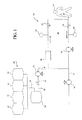
本発明の連続流透析システムおよび方法は、溶質および過剰な水分を患者から効果的に除去するための様々な異なる構成部品および構成を備えることができ、しかも効果的な処置に必要な透析液の量を最小限にする。図1に示すように、本発明は、腹膜透析を受ける患者14内に挿入可能なカテーテル12と連通する流体回路10を備える。これは流体ループ16を画定し、透析液は、この流体ループ16に沿って、患者の腹膜に流入して貫流し、腹膜から流出して連続的に循環し、過剰な水分、並びに尿毒症毒素、たとえば尿素、クレアチニン、尿酸、および/またはその他の類似の成分を含む溶質を処置時に患者から効果的に除去することができる。
The continuous flow dialysis system and method of the present invention can comprise a variety of different components and configurations for effectively removing solutes and excess water from a patient, yet providing the necessary dialysate solution for effective treatment. Minimize the amount. As shown in FIG. 1, the present invention comprises a
(カテーテル)
任意の適切なカテーテル、または医学的に許容可能なその他の刺入デバイスを使用することができる。好ましい一実施態様では、流入内腔および流出内腔を有する2重内腔カテーテルを使用できる。二重内腔カテーテルは、患者の腹腔内に流入して貫流し、腹腔から流出する連続流を提供する。このため、二重内腔カテーテルは、患者内に埋め込まれる。本発明の透析システムに使用するカテーテルの一実施例は、2000年10月12日に出願された米国特許出願第09/689,508号「Peritoneal Dialysis Catheter」に開示されており、この特許の開示事項は、参考として本明細書に援用する。しかし、2個の単一内腔カテーテルは、1個の単一内腔カテーテル同様に使用できる点に注意するべきである。
(catheter)
Any suitable catheter, or other medically acceptable insertion device can be used. In a preferred embodiment, a dual lumen catheter having an inflow lumen and an outflow lumen can be used. A dual lumen catheter provides continuous flow into and out of the patient's abdominal cavity and out of the abdominal cavity. For this reason, a dual lumen catheter is implanted in the patient. One example of a catheter for use in the dialysis system of the present invention is disclosed in US patent application Ser. No. 09 / 689,508 filed Oct. 12, 2000, “Peritoneal Dialysis Catheter”, the disclosure of this patent. Matters are incorporated herein by reference. However, it should be noted that two single lumen catheters can be used as well as one single lumen catheter.
透析液は、概して、それぞれの供給量、循環量および排出量で、処置時に好ましくは連続的に流体ループ内に供給されて循環し、流体ループから排出される。流体ループ内への透析液の供給、および流体ループからの透析液の排出は、処置時に連続的に行なわれるほか、断続的にも行なうことができる点を認識するべきである。たとえば、患者を含む流体ループ内に新たな透析液源を最初に充填した後、透析液は、流体ループに沿って循環することができるため、流体ループ内に追加の量の透析液を注入し、流体を流体ループから排出する必要はない。この最初の循環期間は、治療開始時の適切な時間量で、たとえば約30分間で生じ得る。最初の循環期間後、透析液は次に、残りの処置時間で、好ましくは連続的に流体ループ内に供給され、流体ループから排水される。 The dialysate is generally fed and circulated into and out of the fluid loop, preferably continuously during treatment, at the respective feed rate, circulation rate and discharge rate. It should be recognized that the supply of dialysate into the fluid loop and the discharge of dialysate from the fluid loop can be performed continuously during treatment as well as intermittently. For example, after first filling a fluid loop containing the patient with a new dialysate source, the dialysate can circulate along the fluid loop, thus injecting an additional amount of dialysate into the fluid loop. There is no need to drain fluid from the fluid loop. This initial circulation period may occur for an appropriate amount of time at the start of treatment, for example, about 30 minutes. After the initial circulation period, dialysate is then fed into and drained from the fluid loop, preferably continuously, for the remaining treatment time.
一実施態様では、供給量、循環量および排出量は、透析液が、処置時に、患者の腹膜に出入りして複数回循環した後に、排出されるように、制御可能に調節される。これは、特に、透析液が腹膜内に流入して貫流し、腹膜から流出する単一処理量式または1回通過式を利用する従来の連続流透析療法と比較して、効果的な処置に必要な透析液の量を最小限にすることができる。 In one embodiment, the supply volume, circulation volume, and drainage volume are controllably adjusted so that the dialysate is drained after entering and exiting the patient's peritoneum multiple times during treatment. This is particularly effective for treatment compared to conventional continuous flow dialysis therapy using single-throughput or single-pass dialysis where the dialysate flows into and flows through the peritoneum and out of the peritoneum. The amount of dialysate required can be minimized.
一実施態様では、供給量および排出量は、循環量未満のほぼ等量に維持される。その結果、透析液は、循環量を供給量または排出量で除算した値にほぼ等しい回数だけ、流体ループを複数回通過する。たとえば、供給量および排出量が、循環量の約半分である場合、透析液は、流体ループに沿って約2回通過した後、排出することができる。一実施態様では、透析液は約2回、3回、または供給量もしくは循環量を排出量で除算した値に比例する任意の適切な回数だけ循環することが可能である。 In one embodiment, the feed and discharge are maintained at approximately equal amounts less than the circulation. As a result, the dialysate passes through the fluid loop a number of times, approximately equal to the value of the circulation rate divided by the supply or discharge rate. For example, if the supply and discharge are about half of the circulation, the dialysate can be discharged after passing about twice along the fluid loop. In one embodiment, the dialysate can be circulated approximately two or three times, or any suitable number of times proportional to the supply or circulation divided by the discharge.
供給量、循環量および排出量は、任意の適切な方法で制御可能に維持または調節することができる。一実施態様では、透析液は、流体ループに接続された供給流路18を介して流体ループ内に供給される。図1に示すように、新たな透析液源20は、それぞれ供給流路に沿ってチャンバ24に結合された4個の別個の供給容器22内に収用される。チャンバ24は、新たな透析液源を加熱した後に、流体ループ16内を通過するように構成することができる。以下で述べるとおり、特定の実施態様ではインライン加熱を行なう。しかし、本発明は、バッチタイプの加熱で動作することも可能な点を認識するべきであり、その場合、治療前に、たとえば1個または複数の供給容器22が加熱される。バルブ26および供給ポンプ28は、チャンバ24の下流に配置され、流体ループ16内に流入する新たな透析液を調節する。任意の適切なバルブ、ポンプおよび/またはその他の適切なデバイスを使用して、流れを調節できることを認識するべきである。
Feed, circulation and discharge can be maintained or adjusted in a controllable manner in any suitable manner. In one embodiment, dialysate is supplied into the fluid loop via a
(透析液)
新たな透析液溶液源は、任意の適切なタイプの透析液溶液、好ましくは、腹膜透析療法に特に適するタイプの溶液を含む。一実施態様では、新たな透析液溶液源は、任意の適切かつ効果的な量のデキストロースまたはその他の浸透圧剤を含む。効果的な治療に必要なデキストロースの量は、患者ごとに異なる点を認識するべきである。これに関して、浸透圧剤の量は、患者の特定の必要性を満たす上で異なり、臨床上許容可能な任意のレベル、たとえば約1.5%、約2.5%、約3.5%、約4.25%以上を含むことができる。透析液は、たとえばカルシウム、ナトリウム、カリウム、類似の成分、およびこれらの組合せを含む浸透圧剤のほかに、任意の適切な量およびタイプの電解質を含むことができる。
(Dialysis solution)
The new dialysate solution source comprises any suitable type of dialysate solution, preferably a type particularly suitable for peritoneal dialysis therapy. In one embodiment, the new dialysate solution source includes any suitable and effective amount of dextrose or other osmotic agent. It should be recognized that the amount of dextrose required for effective treatment varies from patient to patient. In this regard, the amount of osmotic agent will vary in meeting the patient's specific needs and can be any clinically acceptable level, such as about 1.5%, about 2.5%, about 3.5%, About 4.25% or more can be included. In addition to osmotic agents including, for example, calcium, sodium, potassium, similar components, and combinations thereof, the dialysate can include any suitable amount and type of electrolyte.
上記のとおり、本発明は、効果的な処置に必要な量の透析液を最小限にすることができる。一実施態様では、処置に必要な新たな透析液は約25リットル以下である。好ましい実施態様では、新たな透析液源は、図1に示すように、各々が約6リットル以下の用量を有する4個の別個の容器22内に保存される。透析液供給容器としては、適切なタイプの容器、たとえば、任意の適切かつ医療上許容可能な材料、たとえば任意の適切なタイプのプラスチック材料から成るバッグなどが挙げられる。
As noted above, the present invention can minimize the amount of dialysate required for effective treatment. In one embodiment, the new dialysate required for treatment is about 25 liters or less. In a preferred embodiment, the fresh dialysate source is stored in four
(加熱器)
上記のとおり、チャンバ24は、新たな透析液源を加熱してから、循環流体ループ16内に供給するように構成することができる。これに関して、最初にシステムに充填する時の透析液の温度は、流体を低い周囲温度で保管した場合は非常に低く、たとえば5℃〜10℃からである可能性がある。一実施態様では、流体加熱器は、流体を所望の温度まで加熱するインライン加熱器(連続流加熱器)であり、流体は、連続的に加熱器を通過して流動する。その他の実施態様では、インライン加熱器以外の加熱器を使用することができ、たとえば、バルク加熱器、赤外加熱器およびプレート加熱器の両方を備えることが可能な二重加熱器、並びにその他の適切な加熱デバイスが挙げられる。
(Heater)
As described above, the
一実施態様では、流体加熱器は、赤外加熱器およびプレート加熱器を含む二重加熱器(図示しない)である。こうした二重加熱器の一実施例は、「Medical Fluid Heater Using Radiant Energy」という表題の特許出願第10/051,609号に開示されており、この出願は、参考として本明細書に援用する。赤外加熱器およびプレート加熱器は共に、連続的に加熱器を通過して流れる医療流体を加熱するインライン加熱器である。放射エネルギーまたは赤外加熱器は、患者ループ内の流体に方向付けられて、こうした流体により吸収される赤外エネルギーを放射し、それにより流体を加熱する。放射エネルギーまたは赤外加熱器は、短時間で、比較的多量の低温流体を所望の温度まで加熱することができる一次加熱器または高能力加熱器である。 In one embodiment, the fluid heater is a double heater (not shown) that includes an infrared heater and a plate heater. One example of such a double heater is disclosed in patent application No. 10 / 051,609, entitled “Medical Fluid Heater Radiant Energy”, which is hereby incorporated by reference. Both infrared heaters and plate heaters are in-line heaters that heat medical fluid that flows continuously through the heater. Radiant energy or infrared heaters are directed to the fluid in the patient loop to radiate infrared energy absorbed by such fluid, thereby heating the fluid. Radiant energy or infrared heaters are primary or high capacity heaters that can heat a relatively large amount of cryogenic fluid to a desired temperature in a short time.
プレート加熱器は、赤外加熱器に対して比較的低い加熱能力を有する二次加熱器または保守加熱器である。プレート加熱器は電気抵抗を使用して、プレートの温度を上昇させ、その結果プレート付近を流動する流体を加熱する。 A plate heater is a secondary or maintenance heater that has a relatively low heating capacity relative to an infrared heater. The plate heater uses electrical resistance to raise the temperature of the plate and consequently heat the fluid flowing near the plate.
高能力および低能力の加熱器の両方を備える加熱器は、様々な流体加熱要件に適応する効率的な加熱器構造を提供する。たとえば、放射または赤外加熱器は、最初のシステム充填時、または透析処置時に著しい熱損失があった場合に、透析システムに供給される低温透析液(熱エネルギー需要が高度)を迅速に加熱する際に特に有用である。初期のシステム充填時における透析液の温度は、流体を低い周囲温度で保存する場合は非常に低く、たとえば5℃〜10℃である。 A heater with both high and low capacity heaters provides an efficient heater structure that accommodates various fluid heating requirements. For example, radiant or infrared heaters quickly heat the cryodialysis fluid (high thermal energy demand) supplied to the dialysis system when there is significant heat loss during the initial system filling or dialysis treatment Especially useful. The temperature of the dialysate at the initial system filling is very low when the fluid is stored at low ambient temperatures, for example 5 ° C to 10 ° C.
プレート加熱器は、たとえば、透析処置時における通常量の熱損失のために、患者に供給される流体の所望の温度(熱エネルギー需要より低い)を維持する上で特に有用である。赤外加熱器は、少量の流体曝露空間における高度の熱需要に備え、プレート加熱器は保守熱需要に備え、赤外加熱器または放射加熱器に比べて、比較的少量の投入エネルギーを要する。さらに、赤外加熱器およびプレート加熱器を一緒に使用して流体を加熱する場合、加熱器の加熱容量は増加する。 Plate heaters are particularly useful in maintaining the desired temperature of the fluid supplied to the patient (below the thermal energy demand), for example, due to the normal amount of heat loss during a dialysis procedure. Infrared heaters provide for high heat demand in a small amount of fluid exposure space, plate heaters provide for maintenance heat demand, and require a relatively small amount of input energy compared to infrared or radiant heaters. Furthermore, when an infrared heater and a plate heater are used together to heat the fluid, the heating capacity of the heater increases.
赤外加熱器およびプレート加熱器は、互いに対して様々な構成で配列することができる。一実施態様における加熱器は、流体が加熱器の側を連続的に通過するように(たとえば、先ず放射加熱器もしくは赤外加熱器、次にプレート加熱器、またはこの逆)配列される。一実施態様では、流体は、各加熱器の側を同時に(両方の加熱器を同時に)通過する。加熱器を通過する流体流路は、両方の加熱器に共通の流路であるか、または各加熱器に個々の流路を備えて良い。放射または赤外、電気抵抗加熱器のほかに、その他のタイプの加熱、たとえば対流、マイクロ波、赤外(「IR」)または誘導加熱を使用しても良い。 Infrared heaters and plate heaters can be arranged in various configurations relative to each other. The heaters in one embodiment are arranged so that fluid passes continuously through the side of the heater (eg, first a radiant heater or an infrared heater, then a plate heater, or vice versa). In one embodiment, the fluid passes through each heater side simultaneously (both heaters simultaneously). The fluid flow path through the heaters may be a common flow path for both heaters, or each heater may have an individual flow path. In addition to radiant or infrared, electrical resistance heaters, other types of heating may be used, such as convection, microwave, infrared ("IR") or induction heating.
一実施態様では、温度センサ(図示しない)は、所望の場所に、たとえば流体ループに沿って設けることができる。温度センサは、加熱器に対応する流体温度を制御するために使用できる様々な流体温度をモニターすることができる。赤外加熱器およびプレート加熱器など、2個以上の加熱器を設ける場合、一実施態様におけるシステムは、各加熱器に別個の温度センサを備えるため、各加熱器を個々に制御することができる。 In one embodiment, a temperature sensor (not shown) can be provided at a desired location, eg, along a fluid loop. The temperature sensor can monitor various fluid temperatures that can be used to control the fluid temperature corresponding to the heater. When providing more than one heater, such as an infrared heater and a plate heater, the system in one embodiment includes a separate temperature sensor for each heater so that each heater can be controlled individually. .
透析液は、流体ループ内に供給された後、一定の循環量で循環する。患者の腹膜内に流入して腹膜を貫流し、腹膜から流出する透析液の循環量は、任意の適切な方法で制御することができる。図1に示すように、1個のポンプ32のほかに、多数のバルブ30が流体ループ16に沿って配置され、透析液を含む治療流体の流れを制御することができる。一実施態様では、循環量は、毎分約300ml以下、好ましくは毎分約100ml〜毎分約200mlの範囲に維持される。
After the dialysate is supplied into the fluid loop, it circulates at a constant circulation rate. The amount of dialysate that flows into and through the peritoneum of the patient and out of the peritoneum can be controlled by any suitable method. As shown in FIG. 1, in addition to a
一旦透析液が流体ループに沿って複数回通過すると、図1に示すように流体ループ16に接続された排出流体流路34を介して流体ループから排水される。ポンプ36は排出流路に接続されて、透析液の排出量を制御する。
Once the dialysate passes a plurality of times along the fluid loop, it is drained from the fluid loop via the exhaust
(モニター)
本発明のシステムおよび方法は、任意の適切な数およびタイプの構成部品を使用して、患者の効果的な処置を促進し、クオリティオブライフ、経済、処置効率、並びにその他の類似の処置条件およびパラメーターを強化することを認識するべきである。たとえば、本発明は、任意の数および適切なタイプのデバイスを使用して、処置時における流体ループをモニターすることができる。一実施態様では、本発明は、任意の適切な数およびタイプのデバイスであって、流体ループ内における空気、水分およびその他の環境汚染の有無をモニターすることが可能なデバイスを備えることができる。一実施態様では、本発明は、酸素および二酸化炭素を含む大気ガスをモニターするための気体センサ38を備えることができる。汚染を検出する場合、本発明は、本発明のシステムから気体を除去し、気体を大気に排出するために任意の適切なデバイスを備えることができる。これは、治療流体に対する細菌汚染などの汚染を防止するために必要である。
(monitor)
The system and method of the present invention uses any suitable number and type of components to facilitate effective treatment of patients, quality of life, economy, treatment efficiency, and other similar treatment conditions and It should be recognized that the parameters will be strengthened. For example, the present invention can use any number and appropriate type of device to monitor fluid loops during treatment. In one embodiment, the present invention may comprise any suitable number and type of devices capable of monitoring the presence or absence of air, moisture and other environmental contamination in the fluid loop. In one embodiment, the present invention may include a
本発明は、一実施態様では、その他の適切なパラメーターをモニターするために、その他の様々なセンサも備えることができる。たとえば、圧力センサ40は、図1に示すように、流体ループに結合して、流体ループに沿った特定の位置における圧力をモニターすることができる。次に、この情報は、制御装置(図示しない)に送信され、その結果、ポンプ、バルブおよびその他が調節されて、患者内に入って患者から出て行くループ内の所望の流体圧力を取得および維持することができる。
The present invention, in one embodiment, can also include a variety of other sensors to monitor other suitable parameters. For example, the
一実施態様では、圧力センサは、非侵襲的圧力センサである。こうした圧力センサは、医療流体または透析液に物理的に接触しない(おそらく、これらを汚染しない)。当然、その他の流量測定装置、たとえば流量センサ、圧力ゲージ、流量計、圧力調整器、オリフィスプレート、質量流量計、容量センサ、または当業者が周知しているその他の適切な流量測定デバイスを適切な個数だけ設けて、流体回路に適応させることができる。 In one embodiment, the pressure sensor is a non-invasive pressure sensor. Such pressure sensors do not make physical contact with the medical fluid or dialysate (possibly not contaminating them). Of course, other flow measurement devices such as flow sensors, pressure gauges, flow meters, pressure regulators, orifice plates, mass flow meters, volume sensors, or other suitable flow measurement devices known to those skilled in the art are suitable. As many as the number can be provided and adapted to the fluid circuit.
一実施態様では、静電容量センサを備える流量測定または容積感知デバイスが設けられ、静電容量センサは、ポンプチャンバ(図示しない)などのチャンバを通ってポンピングされる流体の容積を測定する。容量流体センサは、「Capacitance Fluid Volume Measurement」という表題の特許出願第10/054,487号に詳細に開示されており、この特許出願は、参考として本明細書に援用する。 In one embodiment, a flow measurement or volume sensing device is provided that includes a capacitance sensor, which measures the volume of fluid pumped through a chamber, such as a pump chamber (not shown). A capacitive fluid sensor is disclosed in detail in patent application No. 10 / 054,487 entitled “Capacitance Fluid Volume Measurement”, which is incorporated herein by reference.
2個のコンデンサプレート間の静電容量Cは、関数C=k×(S/d)に従って変化し、ここで、kは誘電定数、Sは個々のプレートの表面積、dはプレート間の距離である。プレート間の静電容量は、関数1/(R×V)に従って比例的に変化し、ここで、Rは既知の抵抗、Vはコンデンサプレートを横断して測定された電圧である。
The capacitance C between the two capacitor plates varies according to the function C = k × (S / d), where k is the dielectric constant, S is the surface area of the individual plates, and d is the distance between the plates. is there. The capacitance between the plates varies proportionally according to the
静電容量センサの一実施態様では、センサは、サイクラーポンプチャンバと協働して動作する。一実施態様におけるサイクラーポンプチャンバは、一定および既知の容積を画定するシェルまたは壁部、並びにシェル間で動作する1対の可撓性膜とを備え、この膜は、膨張して流体が充填され、収縮して流体が排出される。静電容量センサは、ポンプチャンバの対向側部上に配置されたコンデンサプレートを備える。チャンバまたは流体ポンプ内の流体の容積が変化すると(つまり、ポンプチャンバが充填されるか、または空になると)、静電容量プレート間で変化する流体の誘電特性が変化する。たとえば、透析液および空気の結合誘電定数は、チャンバの一定容積のシェル内で、透析液が空気と置換すると(または空気が透析液と置換すると)変化する。全体的な誘電定数の変化は、静電容量プレートの変化に影響し、電圧の対応する変化は、電圧感知デバイスにより感知することができる。制御装置は、電圧感知デバイスにより電圧の変化をモニターし、静電容量の変化と、チャンバを通ってポンピングされる流体の量とを相互に関連付ける(センサの校正後)。 In one embodiment of the capacitive sensor, the sensor operates in conjunction with the cycler pump chamber. The cycler pump chamber in one embodiment comprises a shell or wall that defines a constant and known volume, and a pair of flexible membranes that operate between the shells that are inflated and filled with fluid. , The fluid is discharged by contraction. The capacitance sensor includes a capacitor plate disposed on the opposite side of the pump chamber. As the volume of fluid in the chamber or fluid pump changes (ie, when the pump chamber is filled or emptied), the dielectric properties of the fluid changing between the capacitance plates change. For example, the combined dielectric constant of dialysate and air changes within the constant volume shell of the chamber when dialysate replaces air (or when air replaces dialysate). Changes in the overall dielectric constant affect changes in the capacitance plate, and corresponding changes in voltage can be sensed by the voltage sensing device. The controller monitors the change in voltage with a voltage sensing device and correlates the change in capacitance with the amount of fluid pumped through the chamber (after sensor calibration).
別の実施態様では、チャンバまたはポンプチャンバの容積は、たとえば、チャンバの一方または両方のシェルの移動により変化することができる。この実施態様では、コンデンサプレート間の静電容量は、プレート間の距離dが変化するか、および/または1個または複数のプレートの表面積Sが変化すると変化し、この場合、一方の流体のみが常時コンデンサプレート間に存在するため、誘電定数kは変化しない。測定デバイスのさらに他の別法による実施態様では、コンデンサプレート間の静電容量Cは、誘電定数k、距離dおよび表面積Sの変化の何らかの組合せ、または3つの変化すべてに基づいて変化する。 In another embodiment, the volume of the chamber or pump chamber can be changed, for example, by movement of one or both shells of the chamber. In this embodiment, the capacitance between the capacitor plates changes as the distance d between the plates changes and / or the surface area S of one or more plates changes, in which case only one fluid is present. Since it always exists between the capacitor plates, the dielectric constant k does not change. In yet another alternative embodiment of the measurement device, the capacitance C between the capacitor plates changes based on any combination of changes in the dielectric constant k, distance d and surface area S, or all three changes.
制御装置は、複数のチャンバの充填および排水サイクルによる静電容量の変化から電圧信号の振幅を収集し、ある長さの時間またはある回数のポンプサイクルにわたってポンピングされた医療流体全体の容積を計算する。静電容量センサは、実時間に基づいて、非侵襲的な方法でポンプチャンバに流入するか、またはポンプチャンバから流出する医療流体、たとえば透析液をモニターする。 The controller collects the amplitude of the voltage signal from capacitance changes due to multiple chamber fill and drain cycles and calculates the total volume of the medical fluid pumped over a length of time or a number of pump cycles . Capacitance sensors monitor medical fluid, such as dialysate, that flows into or out of the pump chamber in a non-invasive manner based on real time.
静電容量センサは、透析システムが、患者に提供される流体の容積を望ましい量および流量に維持することを可能にする。患者に対する流量を望ましいレベルに維持することは、腹膜透析療法には特に有利である。 The capacitive sensor enables the dialysis system to maintain the volume of fluid provided to the patient at the desired amount and flow rate. Maintaining the flow rate to the patient at a desired level is particularly advantageous for peritoneal dialysis therapy.
患者に提供される流体を適切な生理的レベルに維持することも望ましい。生理的な制御、たとえば流体のパラメーターの感知および/または調節は、透析システム内の様々な場所で行なうことができる。このため、システムは、生理的レベルの多くの異なるタイプのセンサを何らかの組合せで備えることができる。たとえば、システムは、1個または複数のpHセンサを備えることができる。一実装例では、図3Aおよび図3Bに関連して以下で説明するカートリッジは、流体を調節して、所望の生理的レベルに維持するpHセンサを備えることができる。 It is also desirable to maintain the fluid provided to the patient at an appropriate physiological level. Physiological control, such as sensing and / or adjusting fluid parameters, can be performed at various locations within the dialysis system. Thus, the system can comprise any combination of many different types of sensors at physiological levels. For example, the system can include one or more pH sensors. In one implementation, the cartridge described below in connection with FIGS. 3A and 3B can include a pH sensor that regulates the fluid to maintain a desired physiological level.
図2に示すように、チャンバ24は、流体ループ16に直接結合することができ、透析液は、患者の腹膜内に流入して腹膜を貫流し、腹膜から流出して再循環する前に、チャンバ24を通過することが可能である。これに関して、チャンバは、透析液、特に新たな透析液源を加熱すると共に、使用済み透析液が流体ループに沿って循環する時に、新たな透析液を使用済み透析液と混合するように構成することができる。本明細書で使用する場合、「新たな透析液」またはその他の類似の用語は、流体ループ内に最初に供給される何らかの適切な量およびタイプの透析液であって、患者からのあるレベルの溶質および/または過剰な水分を保持する前の透析液を意味する。本明細書で使用する場合、「使用済み透析液」またはその他の類似の用語は、何らかの適切な量およびタイプの透析液であって、処置時に患者の腹膜内に流入して腹膜を貫流し、腹膜から流出して循環し、その結果、患者からの一定レベルの溶質および過剰な水分を保持している透析液を意味する。
As shown in FIG. 2, the
任意の適切かつ様々な数のポンプ、バルブ、感知デバイスおよびその他の適切な流体回路の構成部品は、透析液の流れが、患者の腹膜内に複数回出入りして通過することができるように、流れを制御するために使用することができる。一実施態様では、透析液の流れを制御するために使用される流体回路の構成部品は、図1に示す構成部品に類似する。図2に適用すると、透析液が流体ループを通って再循環する回数は、供給量を循環量と排出量との間の差で除算した値にほぼ等しい。たとえば、供給量が毎分約50ml、循環量が毎分約102ml、排出量が毎分約52mlである場合、透析液は、排出前に、流体ループに沿って約2回再循環することが可能である。 Any suitable and varying number of pumps, valves, sensing devices, and other suitable fluid circuit components, so that dialysate flow can enter and exit the patient's peritoneum multiple times. Can be used to control the flow. In one embodiment, the fluid circuit components used to control dialysate flow are similar to the components shown in FIG. As applied to FIG. 2, the number of times the dialysate is recirculated through the fluid loop is approximately equal to the supply divided by the difference between the circulation and discharge. For example, if the supply rate is about 50 ml per minute, the circulation rate is about 102 ml per minute, and the discharge rate is about 52 ml per minute, the dialysate can be recirculated about twice along the fluid loop before draining. Is possible.
(容量可変システム)
本発明は、多くの異なる適切な構成部品を使用して、効果的に処置に必要な透析液の量を最小限にすることができる。たとえば、本発明は、処置時における治療流体の容積の変化に対応し、透析液を含む治療流体の使用を最適化できるように構成することができる。本明細書で使用する場合、「治療流体」という用語、またはその他の類似の用語は、透析療法を行なう時に管理することが可能な任意の適切な流体または溶液を意味する。治療流体としては、たとえば、治療の際に使用されていない新たな透析液溶液源、治療時に患者から除去された溶質および代謝老廃物を含む老廃物または使用済み透析液、吸着材料またはその他により浄化された清潔な透析液源、処置時に、患者から流入して、透析液と混合される限外濾過液源、治療流体の拡散特性を強化するのに十分な量の浸透圧剤を含む溶液、その他の適切な溶液、およびこれらの組合せが挙げられる。
(Capacity variable system)
The present invention can use many different suitable components to effectively minimize the amount of dialysate required for treatment. For example, the present invention can be configured to accommodate changes in the volume of the therapeutic fluid during treatment and to optimize the use of the therapeutic fluid including dialysate. As used herein, the term “therapeutic fluid”, or other similar term, means any suitable fluid or solution that can be managed when performing dialysis therapy. The treatment fluid may be purified by, for example, a new dialysate solution source not used during treatment, waste or used dialysate containing solutes and metabolic waste removed from the patient during treatment, adsorbent material or others A clean dialysate source, an ultrafiltrate source that flows from the patient and mixes with the dialysate at the time of treatment, a solution containing an amount of osmotic agent sufficient to enhance the diffusion properties of the treatment fluid, Other suitable solutions, and combinations thereof, can be mentioned.
一実施態様では、本発明は、図3Aおよび図3Bに示すように、患者に接続された流体ループに容量可変連続流を提供するように構成することができる。これに関して、本発明は、上記のとおり、処置時における治療流体の容積の可変増加に適応するように構成することができる。容量可変システムは、任意の適切な数のポンプ、バルブ、流体ラインおよび/またはその他を備えて、処置時における治療流体の使用可能量を増加することができる。これは、たとえば、透析液が患者を透析する時に、流体ループまで通過する限外濾過液の量により、使用可能な治療流体の容積が増加することに適応するために必要である。流体ループに対する限外濾過液および/またはその他の適切な溶液の追加は、実際上、追加の容積が流体ループに接触する状態を維持することにより、溶質を除去する能力を増加することができる。これは、効果的な処置に必要な新たな透析液の量を減少させる効果も有する。 In one embodiment, the present invention can be configured to provide a variable volume continuous flow to a fluid loop connected to a patient, as shown in FIGS. 3A and 3B. In this regard, the present invention can be configured to accommodate variable increases in the volume of therapeutic fluid during treatment, as described above. The variable volume system can include any suitable number of pumps, valves, fluid lines and / or the like to increase the usable amount of therapeutic fluid during the procedure. This is necessary, for example, to accommodate the increase in available therapeutic fluid volume due to the amount of ultrafiltrate that passes to the fluid loop when dialysate dialyzes the patient. The addition of ultrafiltrate and / or other suitable solution to the fluid loop can effectively increase the ability to remove solutes by maintaining additional volume in contact with the fluid loop. This also has the effect of reducing the amount of new dialysate needed for effective treatment.
(追加の浸透圧剤)
一実施態様では、透析液および限外濾過液のほかに追加することができる流体源は、1種類以上の溶液、たとえばデキストロースまたはその他の浸透圧剤を含む水性溶液などを、処置時における治療流体の拡散特性を補うのに十分な量だけ含むことができる。浸透圧剤の量としては、約2.5重量%、約3.5重量%、約4.25重量%以上およびこれらの組合せなどの適切な量が挙げられる。追加の溶液源は、許容可能なレベルおよびタイプの成分、たとえば、カルシウム、マグネシウム、ナトリウムなど、およびこれらの組合せを含む電解質も含むことができる。一実施態様では、流体回路に追加されるデキストロースの量は約6リットル以下である。浸透圧剤溶液は、適切な方法でモニターしつつ、閉鎖流路内に連続的に供給するか、または断続的に供給することができる。
(Additional osmotic agent)
In one embodiment, fluid sources that can be added in addition to dialysate and ultrafiltrate include one or more solutions, such as aqueous solutions containing dextrose or other osmotic agents, and therapeutic fluids during treatment. It can be included in an amount sufficient to compensate for the diffusion characteristics of. The amount of osmotic agent includes suitable amounts such as about 2.5 wt%, about 3.5 wt%, about 4.25 wt% or more, and combinations thereof. Additional solution sources can also include electrolytes containing acceptable levels and types of components, such as calcium, magnesium, sodium, and the like, and combinations thereof. In one embodiment, the amount of dextrose added to the fluid circuit is about 6 liters or less. The osmotic agent solution can be supplied continuously or intermittently in the closed channel while monitoring in an appropriate manner.
効果的な処置を促進するために必要な浸透圧剤溶液、たとえばデキストロースベースの溶液などの量およびタイプは、患者ごとに異なる可能性があることを認識するべきである。一実施態様では、既存の治療流体と比べてより高レベルの浸透圧剤および電解質を含む溶液を、約1リットル以下などの任意の適切な容量で流体回路に供給することができる。一実施態様では、浸透圧剤および電解質の溶液濃縮物は、約4.25重量%以上のデキストロース、および治療溶液中における既存レベルより高度の濃縮レベルの電解質を含むことができ、したがって、治療溶液中のレベルは、再利用の前に、最適かつ生理的に許容可能なレベルになるように調節することができる。 It should be appreciated that the amount and type of osmotic agent solution required to facilitate effective treatment, such as a dextrose-based solution, can vary from patient to patient. In one embodiment, a solution containing higher levels of osmotic agent and electrolyte compared to existing treatment fluids can be delivered to the fluid circuit in any suitable volume, such as about 1 liter or less. In one embodiment, the osmotic agent and electrolyte solution concentrate may comprise about 4.25 wt% or more dextrose and a higher concentration level of electrolyte than existing levels in the treatment solution, and thus the treatment solution. The medium level can be adjusted to an optimal and physiologically acceptable level prior to reuse.
一実施態様では、溶液濃縮物は、流体ループ内に個々に注入することができる。その構成要素としては、たとえば、デキストロース、重炭酸塩、ナトリウム、カルシウム、マグネシウム、類似の成分、およびこれらの組合せなどの浸透圧剤を含有する透析液溶液中に一般に含まれるタイプの成分が挙げられる。流体ループ内に供給される個々の成分の量は、任意の適切な方法で調節および制御することができる。 In one embodiment, the solution concentrate can be injected individually into the fluid loop. Its constituents include, for example, the types of ingredients generally included in dialysate solutions containing osmotic agents such as dextrose, bicarbonate, sodium, calcium, magnesium, similar ingredients, and combinations thereof. . The amount of individual components delivered into the fluid loop can be adjusted and controlled in any suitable manner.
図3Aに示すように、本発明の流体ループ42は、2個のポンプの2個の直列集合44を含むことができる。ポンプ44の集合は、カテーテル48を介して患者46に接続された流路の流入側および流出側に配置される。流体ループ42は、処置時における治療流体の容積の増加を蓄積するように動作可能なチャンバ49も備える。このチャンバは、治療流体の蓄積に適する任意のデバイス、たとえば、透析療法に一般に使用されるバッグなどを備えることができる。同様に、新たな透析液の供給物(図示しない)は、使用時にアキュムレータバッグ49内に供給することができる。これに関して、アキュムレータバッグ49は、新たな透析液を加熱して、および/または流体ループに沿って循環する透析液と混合するように構成することもできる。別法によると、別個のチャンバ(図示しない)を流体ループに結合して、上記のとおり、新たな透析液源を流体ループ内に通過させることができる。
As shown in FIG. 3A, the
一実施態様では、各々のポンプは、毎分約150mlで作動し、平均超過時間で毎分約300mlの循環量を流体ループに沿って提供することができる。これに関して、ポンプの速度は、アキュムレータバッグ49が十分な量の流体容量を有し、透析液が患者の腹膜に流入して貫流し、腹膜から流出する時に、流体ループ内に限外濾過液が流入するために増加する治療流体の量に適応できるように、処置時に調節することが望ましい。患者に出入りする循環量の差は、患者の健康および安全を犠牲にするほど大きくてはならないことを認識するべきである。
In one embodiment, each pump can operate at about 150 ml per minute and provide a circulation rate of about 300 ml per minute along the fluid loop with an average overtime. In this regard, the speed of the pump is such that when the
(カートリッジ)
上記のとおり、透析液は、患者の腹膜内に流入して腹膜を貫流し、腹膜から流出して再循環する前に浄化することができる。これは、効果的な処置に必要な透析液の量を効果的に最小限にするか、または減少させるために使用することもできる。適切な量およびタイプの材料を使用して、再使用の前に透析液を効果的に浄化する任意のタイプのデバイスを使用することができる。一実施態様では、浄化デバイスは、治療時に患者から除去された透析液の溶質を非選択的に除去することが可能な材料を含む。好ましくは、こうした材料は、炭素、活性炭などの任意の適切な吸着材料、またはカートリッジなどの適切な筐体内に何らかの許容可能な方法で収用されるその他の類似材料を含む。
(cartridge)
As described above, the dialysate can be purified before it flows into the patient's peritoneum, flows through the peritoneum, flows out of the peritoneum and recirculates. This can also be used to effectively minimize or reduce the amount of dialysate required for effective treatment. Any type of device can be used that effectively purifies the dialysate prior to reuse, using the appropriate amount and type of material. In one embodiment, the purification device comprises a material capable of non-selectively removing dialysate solutes removed from the patient during treatment. Preferably, such materials include any suitable adsorbent material such as carbon, activated carbon, or other similar material that is admitted in any acceptable manner within a suitable housing such as a cartridge.
一実施態様では、本発明は、溶質を透析液から非選択的に除去することが可能なタイプの材料のほかに、その他の材料を含むことができる。追加のその他の材料としては、たとえば、一定の溶質またはその他を選択的に溶液から除去することができる材料が挙げられる。一実施態様では、追加の材料として、尿素を選択的に除去することが可能な結合材または反応性吸着材料、リン酸塩および/またはその他を選択的に除去することが可能な吸着材料が挙げられる。上記のとおり、溶質、特に尿素の選択的除去が可能な材料を使用すると、本発明のシステムの浄化効率を強化して、効果的な処置に必要な透析液の量を最小限にすることができる。 In one embodiment, the present invention can include other materials in addition to the types of materials that can non-selectively remove solutes from the dialysate. Additional other materials include, for example, materials that can selectively remove certain solutes or others from the solution. In one embodiment, the additional material includes a binder or reactive adsorbent material capable of selectively removing urea, an adsorbent material capable of selectively removing phosphate and / or others. It is done. As noted above, the use of materials capable of selective removal of solutes, particularly urea, can enhance the purification efficiency of the system of the present invention and minimize the amount of dialysate required for effective treatment. it can.
溶質を溶液から選択的に除去することが可能な材料、たとえば結合材料としては、様々な適切かつ異なる材料、たとえば、溶液中の尿素、クレアチニン、その他の類似代謝老廃物および/またはその他などの窒素含有化合物を除去することが可能なポリマー材料が挙げられる。全体として、こうしたタイプの材料は、尿素またはその他の類似溶質と化学的に結合する官能基を含む。 Materials that can selectively remove solutes from solution, such as binding materials, include various suitable and different materials such as nitrogen, such as urea, creatinine, other similar metabolic waste products and / or others in solution. Polymer materials capable of removing contained compounds are mentioned. Overall, these types of materials contain functional groups that chemically bond with urea or other similar solutes.
たとえば、それぞれ参考として本明細書に援用される米国特許第3,933,753号および第4,012,317号には、尿素を化学的に結合するように機能することが可能なフェニルグリオキサールを含有するアルケニル芳香族ポリマーが開示されている。一般に、フェニルグリオキサールポリマー材料は、米国特許第3,933,753号および第4,012,317号に開示されているように、たとえばニトロベンゼン中で行なわれるアセチル化、次に、アセチル基のハロゲン化、およびジメルチルスルホキシドによる処置を介して製造される。尿素などの溶質を溶液から選択的に除去することができるポリマー材料のもう1つの実施例としては、参考として本明細書に援用する米国特許第4,897,200号に開示されているように、通常ニンヒドリンとして周知されているカルボニル基が3個の官能基を含むポリマー材料が挙げられる。しかし、本発明は、上記のとおり、尿素などの溶質を溶液から選択的に除去するために、任意の適切なタイプの材料またはその組合せを含むことができる。 For example, US Pat. Nos. 3,933,753 and 4,012,317, each incorporated herein by reference, include phenylglyoxal that can function to chemically bind urea. An alkenyl aromatic polymer containing is disclosed. In general, phenylglyoxal polymer materials are prepared by acetylation, for example, in nitrobenzene, followed by halogenation of acetyl groups, as disclosed in US Pat. Nos. 3,933,753 and 4,012,317. , And through treatment with dimethyllsulfoxide. Another example of a polymeric material that can selectively remove solutes such as urea from a solution is as disclosed in US Pat. No. 4,897,200, which is incorporated herein by reference. And a polymer material in which the carbonyl group, which is generally known as ninhydrin, contains three functional groups. However, the present invention can include any suitable type of material or combination thereof, as described above, to selectively remove solutes such as urea from the solution.
本発明の浄化カートリッジは、溶質を透析液から除去することが可能な吸着材料のほかに、多くの構成要素を含むことができる。たとえば、浄化カートリッジは、ナトリウム、カリウムまたはその他などの電解質のすべてまたは一部分を透析液溶液から除去する能力を有する。この場合、溶液中の追加の電解質源は、浄化後に透析液の補充を必要とする。カートリッジは、使用する吸着材料に応じて、重炭酸塩またはその他をシステム内に放出するように構成しても良い。これは、透析液のpH調節を容易にすることができる。必要な場合、カートリッジは、タンパク質、粒子状物質または類似の成分がカートリッジから透析液中に浸出または流出するのを防止するため、フィルタを設けると良い。 The purification cartridge of the present invention can include a number of components in addition to the adsorbent material that can remove the solute from the dialysate. For example, the purification cartridge has the ability to remove all or part of the electrolyte, such as sodium, potassium or others, from the dialysate solution. In this case, the additional electrolyte source in the solution requires replenishment of dialysate after purification. The cartridge may be configured to release bicarbonate or other into the system depending on the adsorbent material used. This can facilitate pH adjustment of the dialysate. If necessary, the cartridge may be provided with a filter to prevent protein, particulate matter or similar components from leaching or flowing out of the cartridge into the dialysate.
図3Aに示すように、浄化カートリッジ50は、浄化流体ループ52を介して循環ループ42に結合することができる。カートリッジ50は、炭素層54、リン結合剤層56および尿素結合剤層58など、3個の別個の層を備えることができる。浄化流路52は、浄化流体ループ52を貫流する流量を制御するために、背圧調整器59および/またはその他の適切な構成部品を備えることができる。一実施態様では、浄化流体ループを貫流する透析液の流量、たとえば浄化流量は、循環量より少ない。たとえば、浄化流量および循環量は、それぞれ毎分150mlおよび毎分300mlに維持することができる。
As shown in FIG. 3A, the
図3Bは、本発明の容量可変システムのもう1つの実施態様を示す。このシステムは、処置期間中、平均毎分約120mlで動作する3個のポンプを備える。第1ポンプ60は並列流路62に結合されるため、治療流体をチャンバ64内に供給し、チャンバ64から排出することができる。2個のポンプの直列集合66も、流体ループ68に結合される。ポンプは、図3Bに示すように、患者の腹膜内に流入して貫流し、腹膜から流出する循環量を任意の適切な量、たとえば毎分約300mlの量に制御するように調節することができる。浄化カートリッジ70は、循環流体ループ72を介して循環流体ループ68に結合することができる。浄化カートリッジは、上記のとおり、炭素層74、リン結合剤層76および尿素結合剤層78を備えることができる。上記のとおり、背圧調整器79を設けることも可能である。
FIG. 3B shows another embodiment of the variable capacity system of the present invention. This system comprises three pumps operating at an average of about 120 ml per minute during the treatment period. Since the
透析液が流路に沿って循環する時の、患者内における透析液の量の不確実さは、処置時における循環流量を制御するために使用される構成部品の数およびタイプに応じて変化する可能性があることを認識するべきである。たとえば、循環時の患者内における透析液の量の不確実さは、図3Bに示すポンプが3個の容量可変システムに比べて、図3Aに示すポンプが4個の容量可変システムの場合に大きい。患者の体積の不確実さは、連続流容量可変システムを設計するに当たり、重要な検討材料である。これに関して、不確実さは、治療時のある時点で、患者の体積がどの程度変化する可能性があるかを評価することを要する。システムの調節は、患者の健康および安全を犠牲にしないように、不確実さの計算に基づいて行なうことができる。 When dialysate circulates along the flow path, the uncertainty in the amount of dialysate within the patient varies depending on the number and type of components used to control the circulation flow rate during the procedure. It should be recognized that there is a possibility. For example, the uncertainty in the amount of dialysate in the patient during circulation is greater when the pump shown in FIG. 3A is a variable capacity system with four pumps than in the three capacity variable system shown in FIG. 3B. . Patient volume uncertainty is an important consideration when designing a continuous flow variable volume system. In this regard, uncertainty requires assessing how much the patient's volume can change at some point during treatment. System adjustments can be made based on uncertainty calculations so as not to sacrifice patient health and safety.
上記のとおり、本発明は、患者が、処置時に新たな透析液のバッグを手動で交換する必要がないように自動化することができる。自動化の特徴は、夜間、または患者が通常睡眠する日中の他の時間に使用するのに特に有利である。本発明は、任意の適切な方法、たとえば、任意の数および適切なタイプのデバイスであって、透析液が流体ループ内に連続的に供給され、流体ループ内で循環して流体ループから排出される時に、透析液を含む治療流体の流量を自動的に制御するように構成することができるデバイスを使用することにより自動化することができる。 As noted above, the present invention can be automated so that the patient does not have to manually replace a new dialysate bag during the procedure. The automation feature is particularly advantageous for use at night or at other times during the day when the patient normally sleeps. The present invention may be any suitable method, for example, any number and type of device, wherein dialysate is continuously fed into the fluid loop, circulated within the fluid loop and drained from the fluid loop. Can be automated by using a device that can be configured to automatically control the flow of treatment fluid, including dialysate.
(サイクラー)
一実施態様では、透析液は、サイクラーとして一般に周知されているデバイスを使用して自動的に流体回路内に供給し、流体回路内を循環し、流体回路から排出することができる。本明細書で使用する場合、「サイクラー」という用語、またはその他の類似する用語は、任意の適切な方法で1個または複数の流路に結合されて、流量を自動的に制御できる1個または複数の圧力駆動式ダイアフラム型可変容量ポンプを意味する。サイクラーは、供給される液体の容量を、ポンピング行程前後におけるポンピングチャンバの容積の差として決定することができる。ポンピングチャンバは、一般に、可撓性ダイアフラムにより分割された2個の部分であって、一方の側に空気、他方に流体を有する部分を備える。空気圧が増加すると、液体がチャンバから押し出され、空気側の容積が膨張する。
(Cycler)
In one embodiment, dialysate can be automatically fed into the fluid circuit, circulated through the fluid circuit, and drained from the fluid circuit using a device commonly known as a cycler. As used herein, the term “cycler”, or other similar terms, is coupled to one or more flow paths in any suitable manner to allow for one or more flow rates to be automatically controlled. It means a plurality of pressure-driven diaphragm type variable displacement pumps. The cycler can determine the volume of liquid supplied as the difference in pumping chamber volume before and after the pumping stroke. A pumping chamber is generally comprised of two parts divided by a flexible diaphragm, with air on one side and fluid on the other. As the air pressure increases, liquid is pushed out of the chamber and the volume on the air side expands.
サイクラーの実施例は、米国特許出願「Peritoneal Dialysis Systems and Methods Employing a Liquid Distirbution and Pumping Cassette That Emulates Gravity Flow」、1993年3月3日に出願、出願番号第08/027,328号、米国特許第5,350,357号;「Liquid Pumping Mechanisms for Peritoneal Dialysis Systems Employing Fluid Pressure」、1993年3月3日に出願、出願番号第08/027,485号、米国米国特許第5,431,626号;「Peritoneal Dialysis Systems and Methods Employing Pneumatic Pressure and Temperature−Corrected Liquid Volume Measurements」、1993年3月3日に出願、出願番号第08/026,458号、米国特許第5,474,683号;「Improved User Interface and Monitoring Functions for Automated Peritoneal Dialysis」、1993年3月3日に出願、出願番号第08/025,531号、米国特許第5,438,510号;並びに「Improved User Interface Automated Peritoneal Dialysis Systems」、1993年3月3日に出願、出願番号第08/025,547号、米国特許第5,324,422号;および「Peritoneal Dialysis Cycler」、1993年3月3日に出願、出願番号第08/006,426号、米国特許第D351,470号に開示されており、これらすべての特許の開示事項は、参考として本明細書に援用する。 An example of a cycler is US patent application “Peritoneal Dialysis Systems and Methods Employing a Liquid Distribution and Pumping Casette That Emulations Gravity, No. 3 / No. 3, 1993 / No. No. 5,350,357; “Liquid Pumping Mechanisms for Peritoneal Dialysis Systems Employing Fluid Pressure”, filed March 3, 1993, Application No. 08 / 027,485, US Pat. No. 5,431,626; "Peritoneal Dialysis Sys tems and Methods Employing Pneumatic Pressure and Temperature- Corrected Liquid Volume Measurements, filed on Mar. 3, 1993, application number 08 / 026,458, U.S. Pat. No. 5,474,683, U. "Functions for Automated Peripheral Dialyzation", filed on Mar. 3, 1993, Application No. 08 / 025,531, U.S. Patent No. 5,438,510; and "Improved User Interface Automated Digitalism" , Filed Mar. 3, 1993, application number 08 / 025,547, US Pat. No. 5,324,422; and “Peritoneal Dialysis Cycler”, filed March 3, 1993, application number no. No. 08 / 006,426, U.S. Pat. No. D351,470, the disclosures of all of which are incorporated herein by reference.
本発明の一実施態様によるサイクラーの流体概略図80を図4Aに示す。サイクラーは、第1サイクラーポンプ84と、第2サイクラーポンプ86と、流体ラインに結合されて、透析液を含む治療流体の流量を自動的に制御する一連のバルブ88とを有するマルチライン流体回路82を備える。サイクラーの自動化は、制御装置(図示しない)またはその他の適切なインテリジェンスデバイスにより行なわれる。図4Aに示すように、透析液供給経路90、排出流路92、および循環ループ94は、5個の別個の流体ラインを備えるサイクラーのマルチライン流体回路82に結合される。新たな透析液源96は、チャンバ100を介してサイクラーの第1流体ライン98に結合される。チャンバ100は、上記のとおり、加熱器、混合機および/またはアキュムレータとして動作することができる。
A cycler fluid schematic 80 according to one embodiment of the present invention is shown in FIG. 4A. The cycler has a
一実施態様では、新たな透析液源は、各々がチャンバ100と連通する5個の別個の容器102内に保存される。新たな透析液容器の各々は、約5リットル以下の容積容量を有する。好ましい実施態様では、処置時に約25リットル以下の新たな透析液を使用する。サイクラーの第2流体ライン104は、排出流体流路92に結合される。透析液は、排出された後、処分されるか、または別法により再生してから使用することができる。
In one embodiment, the new dialysate source is stored in five
サイクラーの第3流体ライン106は容器108に結合され、新たな透析液源は、連続流療法が完了した後、容器106から患者の腹膜腔内に供給することができる。これに関して、容器108は、透析液の最後のバッグとして機能し、効果的な時間量にわたって患者内に投与し、滞留してから排出することができる。
The cycler third
サイクラーの第4流体ライン110および第5流体ライン112は、流体ループ94の流出流路114および流入流路116に接続され、その結果、連続流療法時に、透析液が患者の腹膜内に流入して腹膜を貫流し、腹膜から流出して循環することを可能にする。サイクラーは、透析液が、好ましくは連続的に流体ループ内に流入してループ内を循環し、使用後排出するように構成することができる。これに関して、透析液の流量は、透析液が流体ループ内を複数回循環してから、排出するように制御される。サイクラーは、任意の適切な方法で連続流システムに結合することができ、たとえば、患者と流体回路との間の流体界面として使用できる任意の適切な使い捨てカートリッジを使用すると、自動化腹膜透析およびその変更に一般的に使用されるように、患者を流体回路に迅速かつ容易に結合することができる。
The cycler
一実施態様では、流体ループ94に出入りする透析液の供給量および排出量は、流体ループ内の透析液の循環量未満であるほぼ等しい量に維持される。これに関して、透析液を流体ループ94内で循環させることが可能な複数の回数は、循環量を供給量または排出量で除算した値にほぼ等しい。たとえば、図4Aに示すように、供給量および排出量が毎分約50mlに等しく、循環量が毎分約100mlに等しい場合、透析液は、排出前に約2回、患者の腹膜内に流入して循環し、腹膜から流出して循環する。透析液は、任意の適切な回数だけ流体ループに沿って通過することができ、この回数は、循環量を供給量または排出量で除算した値にほぼ等しい。
In one embodiment, the supply and drainage of dialysate entering and exiting the
図4Bに示すように、浄化デバイス118は、サイクラー80を介して循環流体ループ94に結合される浄化流体ループ120または流路に結合される。一実施態様では、図4Aに示すサイクラーの第3流体ライン106は、連続流療法が完了すると、使用時の別個の時点において、浄化流体ループ120内に流入する透析液、および最後のバッグから流体ループ94内に流入する新たな透析液源に適応するように変更される。これは、一度に1個が開放する2個のバルブ122またはその他、たとえばクランプを使用して行なわれる。
As shown in FIG. 4B, the
図4Bに示す流体回路のその他の構成部品は、図4Bの構成部品および流体回路と本質的に同じである。やはり、主な相違は、図4Bは浄化流体ループ120を提供することである。こうしたシステムでは、透析液の流量は、新たな透析液、または浄化ループからの浄化済み透析液と混合された新たな透析液の供給量、浄化ループを貫流する透析液の流量、浄化流体ループからの透析液の排出量、および循環流体ループに沿った透析液の循環量により制御される。一般に、浄化ループの流量は、循環量よりも少量に維持される。たとえば、透析液は、図4Bに示すように、浄化量が毎分約50ml、供給量が毎分約100ml、患者ループから浄化ループ内に流入する流量が毎分約100ml、流体ループに沿って腹膜内に流入する透析液の流入量が毎分約100ml、流体ループに沿って腹膜から流出する透析液の流出量が毎分約103ml、透析液の排出量が毎分約3mlである場合、排出前に循環ループに沿って約2回通過することが可能である。透析液の流量は、透析液が複数回にわたって患者の腹膜内に流入し、腹膜から流出した後に排出するように、任意の適切な量に制御および維持することができることを認識するべきである。
The other components of the fluid circuit shown in FIG. 4B are essentially the same as the components and fluid circuit of FIG. 4B. Again, the main difference is that FIG. 4B provides a
上記のとおり、本発明のシステムおよび方法は、処置時における治療流体の容積の可変性に適応することが可能である。たとえば、容積の増加は、上記のとおり、患者からの限外濾過液の除去、浸透圧剤溶液の追加、および/またはその他による。本発明のシステムは、任意の数の適切な方法で治療流体の増加に適応し、処置時にシステムを使用できるように構成することができる。 As noted above, the systems and methods of the present invention can accommodate the variability of therapeutic fluid volume during treatment. For example, the increase in volume is due to the removal of ultrafiltrate from the patient, the addition of an osmotic agent solution, and / or the like, as described above. The system of the present invention can be configured to accommodate an increase in therapeutic fluid in any number of suitable ways and to use the system during treatment.
一実施態様では、システムは、図5Aおよび図5Bに示すように、第1ポンプ126および第2ポンプ128のほかに、第3ポンプ124などの3個のポンプを備えることができる。これらのポンプは、多数の対応する流体ライン132を介して流体回路130に接続される。多数のバルブ134は、処置時における治療流体の流量を制御および調節するために、流体回路130にも結合される。流体回路130は、患者136内に挿入されたカテーテル138を介して患者136に結合される。浄化カートリッジ140は、上記のとおり、再使用のために治療流体を浄化するために流体回路130にも結合される。任意の適切な数およびタイプの追加のその他の構成部品を流体回路130に結合することができる。たとえば、1個または複数の温度センサ142および圧力センサ144は、任意の所望の位置で流体回路に結合することができる。さらに、流体回路130は、クレアチニンのレベルまたはその他を検出するためのセンサ146などの化学センサを備えることができる。変換器147は、センサ146付近で流体回路に結合することができる。
In one implementation, the system can include three pumps, such as a
透析液は、供給源148を介して流体回路130内にポンピングされる。供給源148は、流体回路130に結合されると共に、使用前に透析液を保存することが可能な任意の適切な容器を備えることができる。一実施態様では、透析液は、約6リットル以下または任意の適切な量の浸透圧剤を含む。透析液は、たとえばカリウム、カルシウム、ナトリウムまたはその他、および/またはこれらの組合せなど、任意の適切な数、タイプおよび量のその他の構成要素を含むことができる。濃縮物源150も、流体回路130に結合することができる。濃縮物源150は、浸透圧剤の濃度が好ましくは透析液源より大きい浸透圧剤溶液などの濃縮物を保存することができる任意の適切な容器を備える。一実施態様では、濃縮物は、約4.25重量%以上の浸透圧剤、たとえばデキストロースを含む。濃縮物は、任意の適切な量、タイプおよび数のその他の構成要素、たとえば電解質も含むことができる。一実施態様では、濃縮物の容積は約3リットル以下である。
Dialysate is pumped into the
治療流体の最後のバッグ152も、流体回路に結合することができる。最後のバッグの治療流体は、任意の適切な量およびタイプの新たな透析液源を含む。最後のバッグの透析液の容積は、複数回処置の終わりに患者の腹腔内にポンピングされ、そこで所望の期間だけ滞留した後、患者から除去された何らかの代謝老廃物および限外濾過液と共に、腹腔から排水される。次に、複数回処置、最後のバッグの充填、滞留および排水サイクルを含む処置サイクルを繰り返すことができる。
A
収集チャンバ154も、流体回路に結合することができる。このチャンバは、治療流体のサンプルを所望の期間で収集するために使用することができる。好ましくは、治療流体は24時間ごとに収集する。このサンプルを分析すると、透析の浄化レベルを検出するなど、処置性能を評価することができる。流体回路は排水経路156をさらに備え、患者に結合された流体回路は、この排水経路156を通して治療流体を排水することができる。
A
複数回処置の開始時に、最初の透析液源148は、流体回路130内にポンピングされる。これは、用途に応じて連続的、断続的、不連続的またはその他の方法で行なうことができる。次に、透析液は、患者136に結合された流体回路130により画定される流体ループに沿って循環し、透析液は、患者の腹腔内に流入して貫流し、腹腔から流出して、代謝老廃物および限外濾過液を除去することができる。透析液は、任意の適切な流量で循環することができ、流量の一実施例を図5Aおよび図5Bに示す。
At the start of multiple treatments, the
透析液が患者136から代謝老廃物および限外濾過液を除去すると、治療流体は容積が増加する可能性がある。さらに、濃縮物150は、処置時の任意の適切な時間に流体回路130内にポンピングし、上記のとおり、代謝老廃物および限外濾過液の除去を促進する。濃縮物の追加も、治療流体の容積を増加させる可能性がある。
As the dialysate removes metabolic waste and ultrafiltrate from the
治療流体の容積が増加すると、透析液源の容器148は、こうした治療流体の増加に適応するために使用することができる。これに関して、治療流体の部分は、図5Aに示すように、流体ライン160に沿って、第2ポンプ128を介して透析液源の容器148内にポンピングすることができる。治療流体の当該部分は、透析液源の容器148内に任意の適切な時間だけ留まり、その後、この部分は、図5Bに示すように、流体ライン162に沿って第3ポンプ124を介して逆に流体回路130内に逆にポンピングすることができる。透析液源の容器148に出入りする治療流体の部分は、治療流体の残余部分が引き続き流体回路130に沿って循環する状態でポンピングを行なうことができる。つまり、透析液源の容器は、流体回路に沿った治療流体の残余部分の循環と並行して、治療流体の一部分を充填するかまたは排水することができる。
As the treatment fluid volume is increased, the
システムは、任意の適切なタイプのポンピング機構を任意の適切な方法で使用し、透析液源容器に流入および/または流出するの並行して、治療流体を流体回路に沿って循環させることができる点を認識するべきである。以下では、この種の流れを干満CFPD流と呼ぶ。これに関して、図5Aおよび図5Bは、本発明の一実施態様によるシステム内で行なわれる干満流の具体的な実施例を示す。本発明のシステムは、任意の適切な方法で構成および動作させて、システムが治療流体容積の可変増加に適応することを可能にする所望の干満流を達成することができる。たとえば、このシステムは追加のポンプ、つまり合計4個のポンプを備えて、システムのポンピング効率を増加させることができる。 The system may use any suitable type of pumping mechanism in any suitable manner to circulate treatment fluid along the fluid circuit in parallel with flowing into and / or out of the dialysate source container. The point should be recognized. Hereinafter, this type of flow is referred to as a tidal CFPD flow. In this regard, FIGS. 5A and 5B show specific examples of tidal flow conducted within a system according to one embodiment of the present invention. The system of the present invention can be configured and operated in any suitable manner to achieve a desired tidal flow that allows the system to adapt to a variable increase in treatment fluid volume. For example, the system can include additional pumps, a total of four pumps, to increase the pumping efficiency of the system.
このシステムは、任意の適切なの数およびタイプの追加のその他の構成部品を備えることができる。たとえば、このシステムは、図5Aおよび図5Bに示す逆流調整器164を備えることができる。このシステムは、治療流体の温度を調節するための加熱機構をさらに備えることができる。たとえば、このシステムは、図5Aおよび図5Bに示すインライン加熱器166を備えることができる。加熱器166は、フィルタまたはその他の適切な構成部品、たとえば空気センサ(図示しない)を備えることも可能である。任意の適切なタイプおよび/または数のフィルタは、任意の適切な方法で、任意の適切な位置において流体回路に結合できる点を認識するべきである。たとえば、フィルタ(図示しない)は、再循環流体を連続的に濾過するように、浄化カートリッジ140と一体にすることができる。一実施態様では、フィルタ(図示しない)は、源148、150および152からの流体がシステム130内に引き込まれる時に流体を濾過するように、供給ライン162に配置することができる。
The system can include any suitable number and type of additional other components. For example, the system can include the
フィルタは、任意の適切な材料から製造し、任意の適切なフィルタサイズを有することが可能である。一実施態様では、フィルタのサイズは約0.3μ、好ましくは、0.22μである。これは、フィルタサイズが約0.3μの場合、サイズが約0.3μ以上である溶液中の溶質を除去することができ、フィルタサイズが約0.22μの場合、約0.22μ以上の溶質を除去できることを意味する。このフィルタは、様々な方法で動作し、本発明の透析システムの性能を強化することができる。 The filter can be made from any suitable material and have any suitable filter size. In one embodiment, the size of the filter is about 0.3μ, preferably 0.22μ. This is because when the filter size is about 0.3μ, the solute in the solution having a size of about 0.3μ or larger can be removed, and when the filter size is about 0.22μ, the solute of about 0.22μ or larger can be removed. Can be removed. This filter can operate in a variety of ways to enhance the performance of the dialysis system of the present invention.
たとえば、このフィルタは、UV汚染除去技術またはその他の代わりに使用すると、治療流体を殺菌した後、治療流体を患者内に流入および貫流させ、患者から流出させることができる。これは、処置の結果としての患者の感染、たとえば、治療時に汚染物に接触することにより感染する可能性がある腹膜炎などを効果的になくすか、または少なくとも大幅に減少させることができる。 For example, the filter, when used in place of UV decontamination technology or otherwise, can allow treatment fluid to flow into and through the patient and out of the patient after the treatment fluid is sterilized. This can effectively eliminate or at least significantly reduce patient infection as a result of treatment, such as peritonitis, which can be transmitted by contact with contaminants during treatment.
1個または複数のフィルタは、任意の適切な位置において流体回路に結合できる点を認識するべきである。患者の流入側では、フィルタは、上記のように患者内に流入する前に、透析液を殺菌するために動作することができる。1個または複数のフィルタは、排出流路にも結合する。この位置では、フィルタは、排出する前に、治療流体から栄養物を除去するために使用することができる。次に、フィルタは、たとえば、適切な溶液を逆流させて浄化し、濾過された栄養物を取り出して再利用し、患者内に再循環させることができる。フィルタは、その濾過効率を強化するために、任意の適切な方法で構成することができる。 It should be appreciated that the filter or filters can be coupled to the fluid circuit at any suitable location. On the inflow side of the patient, the filter can operate to sterilize the dialysate prior to entering the patient as described above. One or more filters are also coupled to the exhaust flow path. In this position, the filter can be used to remove nutrients from the treatment fluid before draining. The filter can then be purified, for example, by refluxing the appropriate solution, removing the filtered nutrients and reusing them for recirculation within the patient. The filter can be configured in any suitable manner to enhance its filtration efficiency.
本発明の流路、流体回路および/または流体ループは、任意の適切な方法で相互に接続された1本または複数の流体ラインから製造することができる点を認識するべきである。流体ラインは、可撓性の無菌および不活性プラスチック、たとえばポリエチレン、ポリスチレン、ポリプロピレン、ポリ塩化ビニルおよび/またはこれらの組合せを含む任意の適切な材料を含むことができる。一般に、流体ラインは、ラインを通る流体の流れを目視観察できるように透明である。 It should be appreciated that the flow paths, fluid circuits and / or fluid loops of the present invention can be manufactured from one or more fluid lines interconnected in any suitable manner. The fluid line can comprise any suitable material including flexible sterile and inert plastics such as polyethylene, polystyrene, polypropylene, polyvinyl chloride and / or combinations thereof. In general, the fluid line is transparent so that the flow of fluid through the line can be visually observed.
本明細書で説明されている本発明の好ましい実施態様に対する様々な変更および改良は、当業者に明らかであることを理解するべきである。このような変更および改良は、本発明の意図および範囲を逸脱することなく、その意図された利益を損なうことなく成され得る。したがって、このような変更および改良は、添付の特許請求の範囲により網羅することを意図している。 It should be understood that various changes and modifications to the preferred embodiments of the invention described herein will be apparent to those skilled in the art. Such changes and modifications can be made without departing from the spirit and scope of the present invention and without diminishing its intended benefits. Accordingly, such modifications and improvements are intended to be covered by the appended claims.
Claims (65)
患者の腹腔と連通する流入内腔および流出内腔を有するカテーテルと、
前記カテーテルと連通し、その結果、患者の腹腔内に流入して貫流し、腹腔から流出するように治療流体を循環させることが可能な流体ループを画定する流体回路と、
前記流体回路に結合された透析液の供給源と、
透析液をある供給量で前記流体回路内にポンピングし、前記流体ループに沿って、ある循環量で前記透析液を循環させて、治療上効果的な量の溶質および過剰な水分を患者から除去するためのサイクラーと、
前記流体ループに結合された排出流体流路であって、治療流体は、前記流体ループを通ってある排出量で前記流体回路から排水され、前記排出量は、治療流体が、排出前に前記流体ループに沿って複数回循環することを可能にする循環量未満である排出流体流路とを備えるシステム。 A system for providing peritoneal dialysis to a patient,
A catheter having an inflow lumen and an outflow lumen in communication with the patient's abdominal cavity;
A fluid circuit defining a fluid loop in communication with the catheter so that the treatment fluid can be circulated to flow into and out of the abdominal cavity of the patient and out of the abdominal cavity;
A source of dialysate coupled to the fluid circuit;
Pumps dialysate into the fluid circuit at a supply rate and circulates the dialysate at a circulation rate along the fluid loop to remove a therapeutically effective amount of solute and excess water from the patient With a cycler to do
An exhaust fluid flow path coupled to the fluid loop, wherein treatment fluid is drained from the fluid circuit at a discharge rate through the fluid loop, the discharge amount being determined by the treatment fluid before the discharge A system comprising an exhaust fluid flow path that is less than a circulation volume that allows multiple circulations along the loop.
患者の腹腔と連通する流入内腔および流出内腔を有するカテーテルと、
前記カテーテルと連通し、その結果、患者の腹腔内に流入して貫流し、腹腔から流出するように治療流体を循環させることが可能な流体ループを画定する流体回路と、
透析液の供給源と、
前記流体ループに結合されたチャンバであって、透析液が、前記流体ループを通って前記流体ループ内に、ある供給量で供給されるチャンバと、
前記透析液を前記流体ループ内にポンピングし、前記流体ループに沿って、ある循環量で前記透析液を循環させて、治療上効果的な量の溶質および過剰な水分を患者から除去するためのサイクラーと、
前記流体ループに結合された排出流体流路であって、治療流体は、前記流体ループを通って、ある排出量で前記流体回路から排水され、前記排出量は、治療流体が、排出前に前記流体ループに沿って複数回循環するのに効果的である排出流体流路とを備えるシステム。 A system for providing peritoneal dialysis to a patient,
A catheter having an inflow lumen and an outflow lumen in communication with the patient's abdominal cavity;
A fluid circuit defining a fluid loop in communication with the catheter so that the treatment fluid can be circulated to flow into and out of the abdominal cavity of the patient and out of the abdominal cavity;
A source of dialysate,
A chamber coupled to the fluid loop, wherein dialysate is fed through the fluid loop into the fluid loop at a supply rate;
For pumping the dialysate into the fluid loop and circulating the dialysate at a circulation rate along the fluid loop to remove a therapeutically effective amount of solute and excess water from the patient. With the cycler,
An exhaust fluid flow path coupled to the fluid loop, wherein the treatment fluid is drained from the fluid circuit through the fluid loop at a discharge volume, the discharge volume being reduced by the treatment fluid before the discharge A system comprising an exhaust fluid flow path that is effective to circulate multiple times along the fluid loop.
患者の腹腔と連通する流入内腔および流出内腔を有するカテーテルと、
前記カテーテルと連通し、その結果、腹腔内に流入して貫流し、腹腔から流出するように治療流体を循環させることが可能な流体ループを画定する流体回路と、
前記流体ループに結合された透析液の供給源と、
前記透析液をある供給量で前記流体ループ内にポンピングし、前記流体ループに沿って、ある循環量で前記透析液を循環させて、治療上効果的な量の溶質および過剰な水分を患者から除去するためのサイクラーと、
浄化流路を介して前記流体ループに結合された浄化デバイスであって、前記透析液を含む治療流体は、前記流体ループ内に再導入される前に、ある浄化量で浄化流路内に供給されて浄化され得る浄化デバイスと、
前記流体ループに結合された排出流体流路であって、前記治療流体を排出前に前記流体ループに沿って複数回循環させるのに効果的なある排出量で、前記排出流体ループを通して治療流体を排水する排出流体流路とを備えるシステム。 A system for providing peritoneal dialysis to a patient,
A catheter having an inflow lumen and an outflow lumen in communication with the patient's abdominal cavity;
A fluid circuit defining a fluid loop in communication with the catheter so that the treatment fluid can be circulated into and out of the abdominal cavity and out of the abdominal cavity;
A source of dialysate coupled to the fluid loop;
The dialysate is pumped into the fluid loop at a supply rate and the dialysate is circulated along the fluid loop at a circulation rate to provide a therapeutically effective amount of solute and excess water from the patient. A cycler to remove,
A purification device coupled to the fluid loop through a purification flow path, wherein the treatment fluid containing the dialysate is supplied into the purification flow path at a certain purification amount before being reintroduced into the fluid loop. And a purification device that can be purified
An exhaust fluid flow path coupled to the fluid loop, wherein the treatment fluid is passed through the exhaust fluid loop at an effective discharge amount to circulate the treatment fluid multiple times along the fluid loop prior to discharge. A system comprising an exhaust fluid flow path for draining.
流体回路を患者の腹膜内のカテーテルと連通させて結合し、それにより流体ループを画定し、治療流体が、前記流体ループに沿って腹膜内に流入して貫流し、腹膜から流出するように循環させることを可能にするステップと、
透析液源を前記流体ループに、ある供給量で供給するステップと、
前記透析液を含む治療流体を前記流体ループに沿って、ある循環量で循環させ、治療上効果的な量の過剰な水分および溶質を患者から除去するステップと、
前記治療流体の流体ループをある排出量で排水するステップと、
前記透析液を排出前に前記流体ループに沿って複数回循環させるステップとを含む方法。 A method of providing peritoneal dialysis to a patient, comprising:
A fluid circuit is coupled in communication with a catheter in the patient's peritoneum, thereby defining a fluid loop, and the treatment fluid circulates in and through the peritoneum along the fluid loop and out of the peritoneum. A step that makes it possible to
Supplying a dialysate source to the fluid loop at a supply rate;
Circulating a therapeutic fluid containing the dialysate along the fluid loop in a circulating amount to remove a therapeutically effective amount of excess water and solutes from the patient;
Draining the treatment fluid fluid loop at a discharge rate;
Circulating the dialysate a plurality of times along the fluid loop prior to draining.
流体回路を患者の腹膜内のカテーテルと連通させて結合し、それにより流体ループを画定し、治療流体が、前記流体ループに沿って腹膜内に流入して貫流し、腹膜から流出するように循環させることを可能にするステップと、
チャンバを前記流体ループに結合するステップと、
透析液の供給源を、前記チャンバを通して前記流体ループに、ある供給量で供給するステップと、
前記透析液を含む治療流体を前記流体ループに沿って、ある循環量で循環させ、治療上効果的な量の過剰な水分および溶質を患者から除去するステップと、
排出前に透析液を前記流体ループに沿って複数回循環させるのに効果的なある排出量で、治療流体を流体ループから排水するステップとを含む方法。 A method of providing peritoneal dialysis to a patient, comprising:
A fluid circuit is coupled in communication with a catheter in the patient's peritoneum, thereby defining a fluid loop, and the treatment fluid circulates in and through the peritoneum along the fluid loop and out of the peritoneum. A step that makes it possible to
Coupling a chamber to the fluid loop;
Supplying a source of dialysate through the chamber to the fluid loop at a supply rate;
Circulating a therapeutic fluid containing the dialysate along the fluid loop in a circulating amount to remove a therapeutically effective amount of excess water and solutes from the patient;
Draining the treatment fluid from the fluid loop in an amount effective to circulate dialysate multiple times along the fluid loop prior to draining.
流体回路を患者の腹膜内のカテーテルと連通させて結合し、それにより流体ループを画定し、治療流体が、前記流体ループに沿って腹膜内に流入して貫流し、腹膜から流出するように循環させることを可能にするステップと、
約25リットル以下の量の透析液の供給源を、ある供給量で前記流体ループに供給するステップと、
透析液を含む治療流体を前記流体ループに沿って循環させ、治療上効果的な量の限外濾過液および溶質を患者から除去するステップと、
治療流体の前記流体ループを、ある排出量で排水するステップと、
排出前に透析液を前記流体ループに沿って複数回循環させるステップとを含む方法。 A method of reducing the amount of dialysate used for dialysis therapy,
A fluid circuit is coupled in communication with a catheter in the patient's peritoneum, thereby defining a fluid loop, and the treatment fluid circulates in and through the peritoneum along the fluid loop and out of the peritoneum. A step that makes it possible to
Supplying a source of dialysate in an amount of about 25 liters or less to the fluid loop at a supply rate;
Circulating a therapeutic fluid containing dialysate along the fluid loop to remove a therapeutically effective amount of ultrafiltrate and solute from the patient;
Draining the fluid loop of treatment fluid with a discharge;
Circulating the dialysate multiple times along the fluid loop prior to draining.
Applications Claiming Priority (2)
| Application Number | Priority Date | Filing Date | Title |
|---|---|---|---|
| US39726802P | 2002-07-19 | 2002-07-19 | |
| PCT/US2003/022709 WO2004008826A2 (en) | 2002-07-19 | 2003-07-16 | Systems and methods for performing peritoneal dialysis |
Related Child Applications (1)
| Application Number | Title | Priority Date | Filing Date |
|---|---|---|---|
| JP2009187893A Division JP4971395B2 (en) | 2002-07-19 | 2009-08-13 | System and method for performing peritoneal dialysis |
Publications (2)
| Publication Number | Publication Date |
|---|---|
| JP2005533560A true JP2005533560A (en) | 2005-11-10 |
| JP2005533560A5 JP2005533560A5 (en) | 2006-08-17 |
Family
ID=30771024
Family Applications (6)
| Application Number | Title | Priority Date | Filing Date |
|---|---|---|---|
| JP2004523195A Pending JP2005533560A (en) | 2002-07-19 | 2003-07-16 | System and method for performing peritoneal dialysis |
| JP2009187893A Expired - Fee Related JP4971395B2 (en) | 2002-07-19 | 2009-08-13 | System and method for performing peritoneal dialysis |
| JP2012046987A Expired - Fee Related JP5636385B2 (en) | 2002-07-19 | 2012-03-02 | System and method for performing peritoneal dialysis |
| JP2015235910A Expired - Fee Related JP6170988B2 (en) | 2002-07-19 | 2015-12-02 | System and method for performing peritoneal dialysis |
| JP2017010439A Expired - Fee Related JP6581609B2 (en) | 2002-07-19 | 2017-01-24 | System and method for performing peritoneal dialysis |
| JP2018025084A Expired - Lifetime JP6921014B2 (en) | 2002-07-19 | 2018-02-15 | Systems and methods for performing peritoneal dialysis |
Family Applications After (5)
| Application Number | Title | Priority Date | Filing Date |
|---|---|---|---|
| JP2009187893A Expired - Fee Related JP4971395B2 (en) | 2002-07-19 | 2009-08-13 | System and method for performing peritoneal dialysis |
| JP2012046987A Expired - Fee Related JP5636385B2 (en) | 2002-07-19 | 2012-03-02 | System and method for performing peritoneal dialysis |
| JP2015235910A Expired - Fee Related JP6170988B2 (en) | 2002-07-19 | 2015-12-02 | System and method for performing peritoneal dialysis |
| JP2017010439A Expired - Fee Related JP6581609B2 (en) | 2002-07-19 | 2017-01-24 | System and method for performing peritoneal dialysis |
| JP2018025084A Expired - Lifetime JP6921014B2 (en) | 2002-07-19 | 2018-02-15 | Systems and methods for performing peritoneal dialysis |
Country Status (8)
| Country | Link |
|---|---|
| US (3) | US7922686B2 (en) |
| EP (2) | EP2338543B1 (en) |
| JP (6) | JP2005533560A (en) |
| AT (1) | ATE509645T1 (en) |
| AU (1) | AU2003274901A1 (en) |
| ES (2) | ES2366781T3 (en) |
| MX (1) | MXPA05000817A (en) |
| WO (1) | WO2004008826A2 (en) |
Cited By (5)
| Publication number | Priority date | Publication date | Assignee | Title |
|---|---|---|---|---|
| JP2009254918A (en) * | 2002-07-19 | 2009-11-05 | Baxter Internatl Inc | System and method for performing peritoneal dialysis |
| JP2013502249A (en) * | 2009-08-19 | 2013-01-24 | フレセニウス・メディカル・ケア・ドイチュラント・ゲーエムベーハー | Tube set for blood processing apparatus and blood processing apparatus having tube set |
| JP2017513666A (en) * | 2014-04-08 | 2017-06-01 | フレゼニウス メディカル ケアー ドイチュラント ゲゼルシャフト ミット ベシュレンクテル ハフツングFresenius Medical Care Deutschland GmbH | Prediction method of treatment duration of peritoneal dialysis treatment |
| JP2017185218A (en) * | 2016-03-31 | 2017-10-12 | 旭化成メディカル株式会社 | Blood purification device and sterilization method |
| JP2019514521A (en) * | 2016-05-06 | 2019-06-06 | ガンブロ ルンディア アー・ベー | System and method for peritoneal dialysis with dialysis fluid preparation at the point of use using a reservoir and disposable set |
Families Citing this family (112)
| Publication number | Priority date | Publication date | Assignee | Title |
|---|---|---|---|---|
| US7241272B2 (en) | 2001-11-13 | 2007-07-10 | Baxter International Inc. | Method and composition for removing uremic toxins in dialysis processes |
| DE10224750A1 (en) | 2002-06-04 | 2003-12-24 | Fresenius Medical Care De Gmbh | Device for the treatment of a medical fluid |
| US7238164B2 (en) | 2002-07-19 | 2007-07-03 | Baxter International Inc. | Systems, methods and apparatuses for pumping cassette-based therapies |
| US8038639B2 (en) | 2004-11-04 | 2011-10-18 | Baxter International Inc. | Medical fluid system with flexible sheeting disposable unit |
| WO2006086490A1 (en) | 2005-02-07 | 2006-08-17 | Medtronic, Inc. | Ion imbalance detector |
| US7935074B2 (en) | 2005-02-28 | 2011-05-03 | Fresenius Medical Care Holdings, Inc. | Cassette system for peritoneal dialysis machine |
| US20060195064A1 (en) * | 2005-02-28 | 2006-08-31 | Fresenius Medical Care Holdings, Inc. | Portable apparatus for peritoneal dialysis therapy |
| US8197231B2 (en) | 2005-07-13 | 2012-06-12 | Purity Solutions Llc | Diaphragm pump and related methods |
| CN101351235B (en) | 2005-12-29 | 2011-06-15 | 弗莱克斯戴尔勒斯私人有限公司 | Method and apparatus for home dialysis |
| US8870811B2 (en) * | 2006-08-31 | 2014-10-28 | Fresenius Medical Care Holdings, Inc. | Peritoneal dialysis systems and related methods |
| US8926550B2 (en) * | 2006-08-31 | 2015-01-06 | Fresenius Medical Care Holdings, Inc. | Data communication system for peritoneal dialysis machine |
| CA2687682C (en) * | 2007-05-29 | 2017-10-31 | Fresenius Medical Care Holdings, Inc. | Solutions, dialysates, and related methods |
| US7892197B2 (en) * | 2007-09-19 | 2011-02-22 | Fresenius Medical Care Holdings, Inc. | Automatic prime of an extracorporeal blood circuit |
| US8449500B2 (en) * | 2007-11-16 | 2013-05-28 | Baxter International Inc. | Flow pulsatility dampening devices for closed-loop controlled infusion systems |
| US9101716B2 (en) | 2008-02-01 | 2015-08-11 | Baxter International Inc. | Multi-pass dialysis |
| US8152116B2 (en) * | 2008-02-27 | 2012-04-10 | Baxter International Inc. | Dialysate bag seal breakage sensor incorporated in dialysate bag management |
| US9348975B2 (en) * | 2008-05-02 | 2016-05-24 | Baxter International Inc. | Optimizing therapy outcomes for peritoneal dialysis |
| US9514283B2 (en) * | 2008-07-09 | 2016-12-06 | Baxter International Inc. | Dialysis system having inventory management including online dextrose mixing |
| US10265454B2 (en) * | 2008-07-25 | 2019-04-23 | Baxter International Inc. | Dialysis system with flow regulation device |
| US20100051552A1 (en) | 2008-08-28 | 2010-03-04 | Baxter International Inc. | In-line sensors for dialysis applications |
| US8182673B2 (en) | 2009-01-29 | 2012-05-22 | Baxter International Inc. | Drain and fill logic for automated peritoneal dialysis |
| US8142649B2 (en) | 2009-01-29 | 2012-03-27 | Baxter International Inc. | Method for optimizing tidal therapies employing ultrafiltrate trending |
| US8192401B2 (en) * | 2009-03-20 | 2012-06-05 | Fresenius Medical Care Holdings, Inc. | Medical fluid pump systems and related components and methods |
| EP2453946B1 (en) | 2009-07-15 | 2013-02-13 | Fresenius Medical Care Holdings, Inc. | Medical fluid cassettes and related systems |
| US8720913B2 (en) * | 2009-08-11 | 2014-05-13 | Fresenius Medical Care Holdings, Inc. | Portable peritoneal dialysis carts and related systems |
| US9399091B2 (en) | 2009-09-30 | 2016-07-26 | Medtronic, Inc. | System and method to regulate ultrafiltration |
| US8366667B2 (en) | 2010-02-11 | 2013-02-05 | Baxter International Inc. | Flow pulsatility dampening devices |
| DE102010053973A1 (en) | 2010-12-09 | 2012-06-14 | Fresenius Medical Care Deutschland Gmbh | Medical device with a heater |
| US9694125B2 (en) | 2010-12-20 | 2017-07-04 | Fresenius Medical Care Holdings, Inc. | Medical fluid cassettes and related systems and methods |
| US9624915B2 (en) | 2011-03-09 | 2017-04-18 | Fresenius Medical Care Holdings, Inc. | Medical fluid delivery sets and related systems and methods |
| MX341315B (en) | 2011-04-21 | 2016-08-12 | Fresenius Medical Care Holdings Inc | Medical fluid pumping systems and related devices and methods. |
| US9848778B2 (en) | 2011-04-29 | 2017-12-26 | Medtronic, Inc. | Method and device to monitor patients with kidney disease |
| US8951219B2 (en) | 2011-04-29 | 2015-02-10 | Medtronic, Inc. | Fluid volume monitoring for patients with renal disease |
| US9456755B2 (en) | 2011-04-29 | 2016-10-04 | Medtronic, Inc. | Method and device to monitor patients with kidney disease |
| MY171156A (en) | 2011-06-24 | 2019-09-27 | Richard W C Lo | Multi-container systems and uses thereof |
| JP6001660B2 (en) | 2011-08-02 | 2016-10-05 | メドトロニック,インコーポレイテッド | Hemodialysis system having a flow path with controlled follow-up volume |
| EP2744537B1 (en) | 2011-08-16 | 2018-01-24 | Medtronic, Inc. | Modular hemodialysis system |
| US9707330B2 (en) | 2011-08-22 | 2017-07-18 | Medtronic, Inc. | Dual flow sorbent cartridge |
| US9186449B2 (en) | 2011-11-01 | 2015-11-17 | Fresenius Medical Care Holdings, Inc. | Dialysis machine support assemblies and related systems and methods |
| EP2800592B1 (en) | 2012-01-04 | 2019-03-06 | Medtronic Inc. | Multi-staged filtration system for blood fluid removal |
| US9610392B2 (en) | 2012-06-08 | 2017-04-04 | Fresenius Medical Care Holdings, Inc. | Medical fluid cassettes and related systems and methods |
| US9500188B2 (en) | 2012-06-11 | 2016-11-22 | Fresenius Medical Care Holdings, Inc. | Medical fluid cassettes and related systems and methods |
| US10905816B2 (en) | 2012-12-10 | 2021-02-02 | Medtronic, Inc. | Sodium management system for hemodialysis |
| US9713666B2 (en) | 2013-01-09 | 2017-07-25 | Medtronic, Inc. | Recirculating dialysate fluid circuit for blood measurement |
| US9707328B2 (en) | 2013-01-09 | 2017-07-18 | Medtronic, Inc. | Sorbent cartridge to measure solute concentrations |
| US11565029B2 (en) | 2013-01-09 | 2023-01-31 | Medtronic, Inc. | Sorbent cartridge with electrodes |
| US11154648B2 (en) | 2013-01-09 | 2021-10-26 | Medtronic, Inc. | Fluid circuits for sorbent cartridge with sensors |
| US9526822B2 (en) | 2013-02-01 | 2016-12-27 | Medtronic, Inc. | Sodium and buffer source cartridges for use in a modular controlled compliant flow path |
| US10010663B2 (en) | 2013-02-01 | 2018-07-03 | Medtronic, Inc. | Fluid circuit for delivery of renal replacement therapies |
| US10543052B2 (en) | 2013-02-01 | 2020-01-28 | Medtronic, Inc. | Portable dialysis cabinet |
| US9623164B2 (en) | 2013-02-01 | 2017-04-18 | Medtronic, Inc. | Systems and methods for multifunctional volumetric fluid control |
| EP2950835B1 (en) * | 2013-02-01 | 2019-04-24 | Medtronic, Inc. | Recirculating dialysate fluid circuit for blood measurement |
| US10850016B2 (en) | 2013-02-01 | 2020-12-01 | Medtronic, Inc. | Modular fluid therapy system having jumpered flow paths and systems and methods for cleaning and disinfection |
| US9827361B2 (en) | 2013-02-02 | 2017-11-28 | Medtronic, Inc. | pH buffer measurement system for hemodialysis systems |
| US9144640B2 (en) | 2013-02-02 | 2015-09-29 | Medtronic, Inc. | Sorbent cartridge configurations for improved dialysate regeneration |
| US20140263062A1 (en) | 2013-03-14 | 2014-09-18 | Fresenius Medical Care Holdings, Inc. | Universal portable machine for online hemodiafiltration using regenerated dialysate |
| CN109172900B (en) | 2013-03-14 | 2021-06-04 | 贝克斯特国际公司 | System and method for peritoneal dialysis exchange with reusable energy supply unit |
| US9433720B2 (en) | 2013-03-14 | 2016-09-06 | Fresenius Medical Care Holdings, Inc. | Universal portable artificial kidney for hemodialysis and peritoneal dialysis |
| US9561323B2 (en) | 2013-03-14 | 2017-02-07 | Fresenius Medical Care Holdings, Inc. | Medical fluid cassette leak detection methods and devices |
| US9772386B2 (en) | 2013-03-15 | 2017-09-26 | Fresenius Medical Care Holdings, Inc. | Dialysis system with sample concentration determination device using magnet and radio frequency coil assemblies |
| US9713664B2 (en) | 2013-03-15 | 2017-07-25 | Fresenius Medical Care Holdings, Inc. | Nuclear magnetic resonance module for a dialysis machine |
| US9597439B2 (en) | 2013-03-15 | 2017-03-21 | Fresenius Medical Care Holdings, Inc. | Medical fluid sensing and concentration determination using radio frequency energy and a magnetic field |
| US9566377B2 (en) | 2013-03-15 | 2017-02-14 | Fresenius Medical Care Holdings, Inc. | Medical fluid sensing and concentration determination in a fluid cartridge with multiple passageways, using a radio frequency device situated within a magnetic field |
| US9433718B2 (en) | 2013-03-15 | 2016-09-06 | Fresenius Medical Care Holdings, Inc. | Medical fluid system including radio frequency (RF) device within a magnetic assembly, and fluid cartridge body with one of multiple passageways disposed within the RF device, and specially configured cartridge gap accepting a portion of said RF device |
| US10117985B2 (en) | 2013-08-21 | 2018-11-06 | Fresenius Medical Care Holdings, Inc. | Determining a volume of medical fluid pumped into or out of a medical fluid cassette |
| WO2015066731A2 (en) | 2013-11-04 | 2015-05-07 | Medtronic, Inc. | Method and device to manage fluid volumes in the body |
| US10537875B2 (en) | 2013-11-26 | 2020-01-21 | Medtronic, Inc. | Precision recharging of sorbent materials using patient and session data |
| US10004839B2 (en) | 2013-11-26 | 2018-06-26 | Medtronic, Inc. | Multi-use sorbent cartridge |
| US9884145B2 (en) | 2013-11-26 | 2018-02-06 | Medtronic, Inc. | Parallel modules for in-line recharging of sorbents using alternate duty cycles |
| US9895477B2 (en) | 2013-11-26 | 2018-02-20 | Medtronic, Inc. | Detachable module for recharging sorbent materials with optional bypass |
| US10052612B2 (en) | 2013-11-26 | 2018-08-21 | Medtronic, Inc. | Zirconium phosphate recharging method and apparatus |
| US9943780B2 (en) | 2013-11-26 | 2018-04-17 | Medtronic, Inc. | Module for in-line recharging of sorbent materials with optional bypass |
| EP3073911A4 (en) | 2013-11-27 | 2017-07-19 | Medtronic Inc. | Precision dialysis monitoring and synchonization system |
| US10286135B2 (en) | 2014-03-28 | 2019-05-14 | Fresenius Medical Care Holdings, Inc. | Measuring conductivity of a medical fluid |
| WO2015199766A1 (en) | 2014-06-24 | 2015-12-30 | Medtronic, Inc. | Modular dialysate regeneration assembly |
| WO2015199760A1 (en) | 2014-06-24 | 2015-12-30 | Medtronic, Inc. | Replenisihing urease in dialysis systems using a urease introducer |
| US10286380B2 (en) | 2014-06-24 | 2019-05-14 | Medtronic, Inc. | Sorbent pouch |
| EP3160529B1 (en) | 2014-06-24 | 2019-11-13 | Medtronic Inc. | Replenishing urease in dialysis systems using urease pouches |
| US10357757B2 (en) | 2014-06-24 | 2019-07-23 | Medtronic, Inc. | Stacked sorbent assembly |
| EP3160532B1 (en) | 2014-06-24 | 2019-09-18 | Medtronic Inc. | A urease introduction system for replenishing urease in a sorbent cartridge |
| US10098993B2 (en) | 2014-12-10 | 2018-10-16 | Medtronic, Inc. | Sensing and storage system for fluid balance |
| US10874787B2 (en) | 2014-12-10 | 2020-12-29 | Medtronic, Inc. | Degassing system for dialysis |
| US9713665B2 (en) | 2014-12-10 | 2017-07-25 | Medtronic, Inc. | Degassing system for dialysis |
| US9895479B2 (en) | 2014-12-10 | 2018-02-20 | Medtronic, Inc. | Water management system for use in dialysis |
| KR101931854B1 (en) * | 2015-08-27 | 2018-12-24 | 라이프리버 주식회사 | peritoneal circulation apparatus and bioartificial liver support system using the same |
| WO2017034151A1 (en) * | 2015-08-27 | 2017-03-02 | 라이프리버 주식회사 | Peritoneal circulation device and bioartificial liver system using same |
| US10258728B2 (en) | 2015-09-25 | 2019-04-16 | Medtronic, Inc. | Selective sorbent-based regeneration dialysis systems and methods |
| WO2017078965A1 (en) | 2015-11-06 | 2017-05-11 | Medtronic, Inc | Dialysis prescription optimization for decreased arrhythmias |
| US10994064B2 (en) | 2016-08-10 | 2021-05-04 | Medtronic, Inc. | Peritoneal dialysate flow path sensing |
| US10874790B2 (en) | 2016-08-10 | 2020-12-29 | Medtronic, Inc. | Peritoneal dialysis intracycle osmotic agent adjustment |
| US10744253B2 (en) * | 2016-08-10 | 2020-08-18 | Medtronic, Inc. | Adaptive peritoneal dialysis intra-session adjustments for overall session optimization |
| US10758659B2 (en) * | 2016-08-10 | 2020-09-01 | Medtronic, Inc. | Peritoneal dialysis filtrate sampling and adaptive prescription |
| US11013843B2 (en) | 2016-09-09 | 2021-05-25 | Medtronic, Inc. | Peritoneal dialysis fluid testing system |
| JP6802034B2 (en) * | 2016-10-21 | 2020-12-16 | 株式会社メテク | Infusion system |
| US10981148B2 (en) | 2016-11-29 | 2021-04-20 | Medtronic, Inc. | Zirconium oxide module conditioning |
| JP2018105622A (en) * | 2016-12-22 | 2018-07-05 | テルモ株式会社 | Pressure sensor and extracorporeal circulation device |
| US11167070B2 (en) | 2017-01-30 | 2021-11-09 | Medtronic, Inc. | Ganged modular recharging system |
| KR101880585B1 (en) * | 2017-03-22 | 2018-07-23 | 서울대학교산학협력단 | Peritoneal dialysis fluid osmotic pressure regulator |
| US11135345B2 (en) | 2017-05-10 | 2021-10-05 | Fresenius Medical Care Holdings, Inc. | On demand dialysate mixing using concentrates |
| US10960381B2 (en) | 2017-06-15 | 2021-03-30 | Medtronic, Inc. | Zirconium phosphate disinfection recharging and conditioning |
| US11278654B2 (en) | 2017-12-07 | 2022-03-22 | Medtronic, Inc. | Pneumatic manifold for a dialysis system |
| US11033667B2 (en) | 2018-02-02 | 2021-06-15 | Medtronic, Inc. | Sorbent manifold for a dialysis system |
| US11110215B2 (en) | 2018-02-23 | 2021-09-07 | Medtronic, Inc. | Degasser and vent manifolds for dialysis |
| US11213616B2 (en) | 2018-08-24 | 2022-01-04 | Medtronic, Inc. | Recharge solution for zirconium phosphate |
| US11504458B2 (en) | 2018-10-17 | 2022-11-22 | Fresenius Medical Care Holdings, Inc. | Ultrasonic authentication for dialysis |
| US11806457B2 (en) | 2018-11-16 | 2023-11-07 | Mozarc Medical Us Llc | Peritoneal dialysis adequacy meaurements |
| US11806456B2 (en) | 2018-12-10 | 2023-11-07 | Mozarc Medical Us Llc | Precision peritoneal dialysis therapy based on dialysis adequacy measurements |
| WO2020148577A1 (en) * | 2019-01-18 | 2020-07-23 | Insense Medical Ltd. | Continuous equilibrium-based diagnostic and therapeutic system |
| CN111498207B (en) * | 2019-01-30 | 2023-05-02 | 百特国际有限公司 | Medical fluid container preparation system and method |
| US11850344B2 (en) | 2021-08-11 | 2023-12-26 | Mozarc Medical Us Llc | Gas bubble sensor |
| US11944733B2 (en) | 2021-11-18 | 2024-04-02 | Mozarc Medical Us Llc | Sodium and bicarbonate control |
| WO2023170680A1 (en) | 2022-03-08 | 2023-09-14 | Equashield Medical Ltd | Fluid transfer station in a robotic pharmaceutical preparation system |
Citations (1)
| Publication number | Priority date | Publication date | Assignee | Title |
|---|---|---|---|---|
| JPS52115598A (en) * | 1976-02-13 | 1977-09-28 | Ramot Plastics | Peritoneal artificial liver |
Family Cites Families (378)
| Publication number | Priority date | Publication date | Assignee | Title |
|---|---|---|---|---|
| US2732893A (en) | 1956-01-31 | harris | ||
| US2122509A (en) | 1935-08-22 | 1938-07-05 | Stephen B Beliaeff | Hair waving or curling device |
| US2286613A (en) * | 1939-06-08 | 1942-06-16 | Pomona Pump Company | Liquid supply system |
| US2529028A (en) | 1947-07-31 | 1950-11-07 | Landon Standard Pools | Chemical feeder |
| DE1226740B (en) | 1963-07-25 | 1966-10-13 | Hofer Andreas | Display device for diaphragm rupture on diaphragm compressors |
| US3327115A (en) * | 1964-10-12 | 1967-06-20 | Polaroid Corp | Apparatus for holding a photosensitive sheet in a film package with an inflatable bag |
| US3332737A (en) | 1965-01-28 | 1967-07-25 | Kurt A Kraus | Process for separating inorganic anions with hydrous oxide anion exchangers |
| US3388803A (en) | 1965-04-16 | 1968-06-18 | Applied Biolog Sciences Lab In | Wearable dialysis apparatus |
| US3463728A (en) | 1967-04-28 | 1969-08-26 | Us Health Education & Welfare | Dialysate capacity augmentation process |
| US3485245A (en) | 1967-06-21 | 1969-12-23 | Ibm | Portable fluid heater |
| GB1189458A (en) | 1967-09-27 | 1970-04-29 | Nat Res Dev | Improvements in or relating to dialysers |
| US3545438A (en) * | 1968-02-12 | 1970-12-08 | Sarns Inc | Intermittent dialysis method and apparatus therefor |
| US3825493A (en) | 1972-09-29 | 1974-07-23 | Hydronautics | Peritoneal artificial kidney |
| US3799873A (en) | 1968-04-19 | 1974-03-26 | Hydronautics | Artificial kidney |
| US3490479A (en) | 1968-07-12 | 1970-01-20 | Honeywell Inc | Fluid pressure relay |
| US3669878A (en) | 1968-12-02 | 1972-06-13 | Health Education And Welfare U | Treatment of dialysate solution for removal of urea |
| FR2036413A5 (en) | 1969-03-13 | 1970-12-24 | Thomson Csf | |
| SE331736B (en) | 1969-06-04 | 1971-01-11 | Lkb Medical Ab | |
| GB1280521A (en) | 1969-06-28 | 1972-07-05 | Whitely Lang And Neill Ltd | Peritoneal dialysis apparatus |
| US3669880A (en) | 1969-06-30 | 1972-06-13 | Cci Aerospace Corp | Recirculation dialysate system for use with an artificial kidney machine |
| US3667612A (en) | 1969-09-04 | 1972-06-06 | Joe H Leonard | Artificial kidney system |
| BE759038A (en) | 1969-11-17 | 1971-04-30 | Cci Aerospace Corp | RECIRCULATION DIALYSAT MODULE, INTENDED TO BE DISCARDED |
| DE1964735A1 (en) | 1969-12-23 | 1971-07-08 | Hauni Werke Koerber & Co Kg | Peritoneal dialysis machine |
| US3619423A (en) | 1970-04-20 | 1971-11-09 | Us Health Education & Welfare | Cascade dialysis apparatus and method |
| US3689204A (en) | 1970-05-18 | 1972-09-05 | Gen Motors Corp | Laminated liquid pump and method of making same |
| US3626670A (en) | 1970-06-30 | 1971-12-14 | Vernitron Corp | Fluid circulation apparatus including deaeration and negative pressure control |
| US3682817A (en) | 1970-08-02 | 1972-08-08 | Bio Cal Instr Co | Dialyzer |
| US3707967A (en) | 1970-10-01 | 1973-01-02 | Tecna Corp | Steady flow regenerative peritoneal dialysis system and method |
| US3656873A (en) | 1970-11-06 | 1972-04-18 | Peter Schiff | Pulsatile by-pass blood pump |
| US3709222A (en) | 1970-12-28 | 1973-01-09 | Sarns Inc | Method and apparatus for automatic peritoneal dialysis |
| DE2239254C2 (en) | 1970-12-30 | 1983-08-04 | Organon Teknika Corp., Oklahoma City, Okla. | "Column for regenerating a circulating dialysate solution and using this column". |
| US3727612A (en) | 1971-01-18 | 1973-04-17 | R Sayers | Dialysis method and apparatus |
| US3697418A (en) | 1971-01-25 | 1972-10-10 | Cci Aerospace Corp | Method and apparatus for regenerating the dialyzing fluid for an artificial kidney |
| FR2129165A5 (en) | 1971-03-17 | 1972-10-27 | Rhone Poulenc Sa | |
| US3850835A (en) | 1971-11-08 | 1974-11-26 | Cci Life Systems Inc | Method of making granular zirconium hydrous oxide ion exchangers, such as zirconium phosphate and hydrous zirconium oxide, particularly for column use |
| BE792314A (en) | 1971-12-06 | 1973-06-05 | Rhone Poulenc Sa | DEVELOPMENT IN ARTIFICIAL KIDNEYS |
| US4012317A (en) | 1972-02-04 | 1977-03-15 | Rhone-Poulenc S.A. | Process for extracting urea from a solution with alkenylaromatic polymers with α-ketoalhydic groups |
| FR2170868B1 (en) | 1972-02-04 | 1976-07-09 | Rhone Poulenc Ind | |
| US3792643A (en) | 1972-02-17 | 1974-02-19 | R Scheafer | Fluid system |
| US3878564A (en) | 1972-04-14 | 1975-04-22 | Shang J Yao | Blood and tissue detoxification method |
| US3979284A (en) | 1972-07-31 | 1976-09-07 | Rhone-Poulenc S.A. | Artificial haemodialysis kidneys |
| US3911915A (en) | 1972-09-05 | 1975-10-14 | Einstein Coll Med | Dialytic introduction of maltose into bloodstream |
| US3809241A (en) | 1973-02-23 | 1974-05-07 | Electro Sys Eng Inc | Self-container kidney dialysis apparatus |
| US4036747A (en) | 1973-02-27 | 1977-07-19 | Takeda Chemical Industries, Ltd. | Adsorbent for recycling artificial kidney |
| US3884808A (en) | 1973-06-20 | 1975-05-20 | Res Dev Systems Inc | Wearable, self-regenerating dialysis appliance |
| US4192748A (en) | 1973-07-05 | 1980-03-11 | Hyden Viktor H | Dialysis apparatus with selective chemical activity |
| USRE32303E (en) | 1973-07-31 | 1986-12-09 | American Medical Products Corp. | Peritoneal dialysis apparatus |
| JPS5225197B2 (en) | 1973-09-19 | 1977-07-06 | ||
| GB1433758A (en) | 1973-10-23 | 1976-04-28 | Hamilton T W | Membrane pump |
| DE2355966A1 (en) * | 1973-11-09 | 1975-05-22 | Medac Klinische Spezialpraep | PUMP ARRANGEMENT, ESPECIALLY FOR BLOOD PUMPS |
| US4118314A (en) | 1974-01-09 | 1978-10-03 | Seisan Kaihatsu Kagaku Kenkyusho | Apparatus for treatment of artificial kidney dialyzing fluid |
| US3902490A (en) | 1974-03-27 | 1975-09-02 | Univ Utah | Portable artificial kidney system |
| US4031010A (en) | 1974-05-02 | 1977-06-21 | Takeda Chemical Industries, Ltd. | Combined dialyzer and adsorber unit |
| IT1014620B (en) | 1974-05-06 | 1977-04-30 | Bellco Spa | PROCEDURE FOR THE REGENERATION OF DIALIZING LIQUIDS IN HEMODIALYSIS SYSTEMS |
| US4158530A (en) | 1974-07-01 | 1979-06-19 | Bernstein Robert E | Pumping apparatus comprising two collapsible chambers |
| US3976574A (en) | 1974-11-04 | 1976-08-24 | Cobe Laboratories, Inc. | Negative pressure control system |
| US4126132A (en) | 1975-07-28 | 1978-11-21 | Andros Incorporated | Intravenous and intra arterial delivery system |
| US4081372A (en) * | 1975-12-08 | 1978-03-28 | University Of Utah | Leakage indicator for recirculating peritoneal dialysis system |
| US4086653A (en) | 1976-01-09 | 1978-04-25 | Thermo Electron Corporation | Pneumatic pump monitor |
| CA1110137A (en) | 1976-05-24 | 1981-10-06 | Ingemar H. Lundquist | Intravenous liquid pumping system and method |
| DE2705734C3 (en) | 1977-02-11 | 1982-04-22 | Akzo Gmbh, 5600 Wuppertal | Dialysis membrane for hemodialysis |
| SE402212B (en) | 1976-10-14 | 1978-06-26 | Gambro Ab | DIALYSIS SYSTEM |
| US4194536A (en) | 1976-12-09 | 1980-03-25 | Eaton Corporation | Composite tubing product |
| US4140118A (en) | 1977-03-09 | 1979-02-20 | Andros Incorporated | Cassette chamber for intravenous delivery system |
| FR2385406A1 (en) | 1977-03-28 | 1978-10-27 | Akzo Nv | ARTIFICIAL KIDNEY |
| NL7703937A (en) | 1977-04-12 | 1978-10-16 | Organon Teknika Bv | DEVICE EQUIPPED WITH A SORBENT FOR THE PURIFICATION OF BLOOD; A SORBENT SUITABLE FOR ORAL USE AND A PROCESS FOR MANUFACTURE OF THE SORBENT. |
| US4173537A (en) | 1977-05-23 | 1979-11-06 | Newhart Earle E | Integral artificial kidney unit |
| US4142524A (en) | 1977-06-02 | 1979-03-06 | Andros Incorporated | Cassette for intravenous delivery system |
| US4199307A (en) | 1977-07-05 | 1980-04-22 | Andros Incorporated | Medical infusion system |
| DE2734248A1 (en) | 1977-07-29 | 1979-02-08 | Fresenius Chem Pharm Ind | PORTABLE ARTIFICIAL KIDNEY |
| US4190047A (en) | 1977-08-26 | 1980-02-26 | University Of Utah | Method and apparatus for peritoneal dialysis |
| US4364747A (en) | 1977-08-29 | 1982-12-21 | The Regents Of The University Of Minnesota | System for regenerative thermally reversed adsorption |
| DE2755214C3 (en) | 1977-12-10 | 1980-12-11 | Dr. Eduard Fresenius Chemisch-Pharmazeutische Industrie Kg Apparatebau Kg, 6380 Bad Homburg | Device for periodic irrigation of the abdominal cavity |
| US4187057A (en) | 1978-01-11 | 1980-02-05 | Stewart-Naumann Laboratories, Inc. | Peristaltic infusion pump and disposable cassette for use therewith |
| IT1092077B (en) | 1978-01-20 | 1985-07-06 | Bellco Spa | PORTABLE MACHINE FOR REGENERATION DIALYSIS |
| JPS54109291A (en) | 1978-02-16 | 1979-08-27 | Genshirou Ogawa | Heater structure for instillation liquid* transfusion blood or like |
| US4181245A (en) | 1978-02-17 | 1980-01-01 | Baxter Travenol Laboratories, Inc. | Casette for use with an I.V. infusion controller |
| US4273121A (en) | 1978-02-17 | 1981-06-16 | Andros Incorporated | Medical infusion system |
| US4581141A (en) | 1978-02-27 | 1986-04-08 | Purdue Research Foundation | Dialysis material and method for removing uremic substances |
| US4256718A (en) | 1978-03-20 | 1981-03-17 | Organon Teknika Corporation | Sodium zirconium carbonate compound and the method of its preparation |
| JPS6210455Y2 (en) | 1978-04-07 | 1987-03-11 | ||
| IT1174707B (en) | 1978-05-03 | 1987-07-01 | Bonomini Vittorio | PORTABLE ARTIFICIAL KIDNEY FOR DIALYSIS |
| DE2838414C2 (en) | 1978-09-02 | 1984-10-31 | Fresenius AG, 6380 Bad Homburg | Device for hemodialysis and for withdrawing ultrafiltrate |
| US4265601A (en) | 1978-09-05 | 1981-05-05 | Harold Mandroian | Three valve precision pump apparatus with head pressure flowthrough protection |
| SE428427B (en) | 1979-01-04 | 1983-07-04 | Gambro Lundia Ab | WANT TO DISPOSE WASTE METABOLITES SPECIFICALLY NON-GIFTING POISONS, FROM A SOLUTION THROUGH ALTERNATE ADSORPTION AND DESORPTION |
| US4247393A (en) | 1979-01-11 | 1981-01-27 | Wallace Richard A | Hemodialysis assist device |
| US4360507A (en) | 1979-01-24 | 1982-11-23 | Organon Teknika Corporation | Sodium zirconium carbonate compound and the method of its preparation |
| US4277226A (en) | 1979-03-09 | 1981-07-07 | Avi, Inc. | IV Pump with empty supply reservoir and occlusion detector |
| US4382753A (en) | 1979-03-09 | 1983-05-10 | Avi, Inc. | Nonpulsating IV pump and disposable pump chamber |
| US4410322A (en) | 1979-03-09 | 1983-10-18 | Avi, Inc. | Nonpulsating TV pump and disposable pump chamber |
| US4391600A (en) | 1979-03-09 | 1983-07-05 | Avi, Inc. | Nonpulsating IV pump and disposable pump chamber |
| US4236880A (en) | 1979-03-09 | 1980-12-02 | Archibald Development Labs, Inc. | Nonpulsating IV pump and disposable pump chamber |
| IL56975A (en) | 1979-03-29 | 1982-09-30 | Ramot Plastics | Diaphragm pump |
| US4303376A (en) * | 1979-07-09 | 1981-12-01 | Baxter Travenol Laboratories, Inc. | Flow metering cassette and controller |
| SE7905956L (en) | 1979-07-09 | 1981-01-10 | Gambro Dialysatoren | COLUMN FOR TREATMENT OF A LIQUID MEDIUM A PARTICULAR MATERIAL |
| US4276175A (en) | 1979-07-19 | 1981-06-30 | Bower John D | Regeneratable peritoneal dialysis bag |
| US4252651A (en) | 1979-08-29 | 1981-02-24 | Baxter Travenol Laboratories, Inc. | Negative pressure valving system and transmembrane pressure alarm system |
| IT7943514A0 (en) | 1979-10-26 | 1979-10-26 | Buoncristiani Vincenzo | AUTOMATIC EQUIPMENT FOR PERITONEAL DIALYSIS WITH RECYCLING OF THE DISCHARGE LIQUID DURING THE DIALYTIC SESSION |
| US4334838A (en) | 1980-01-29 | 1982-06-15 | The Coca-Cola Company | Diaphragm type fluid pump having a flexible diaphragm with an internal reinforcing plate |
| JPS6111571Y2 (en) | 1980-01-30 | 1986-04-11 | ||
| US4532414A (en) | 1980-05-12 | 1985-07-30 | Data Chem., Inc. | Controlled temperature blood warming apparatus |
| US4316466A (en) | 1980-06-27 | 1982-02-23 | Biomedics, Inc. | Body fluid drainage device |
| CA1188998A (en) | 1980-11-12 | 1985-06-18 | Stephen R. Ash | System and method for controlling and monitoring blood or biologic fluid flow |
| ATE10670T1 (en) | 1980-12-29 | 1984-12-15 | Lewa Herbert Ott Gmbh + Co. | DIAPHRAGM PUMP WITH RELIEVED CLAMPED DIAPHRAGM. |
| DE3101159C2 (en) | 1981-01-16 | 1985-08-22 | Udipi Ramakrishna Dr. 5100 Aachen Shettigar | Process for purifying blood and artificial kidney for carrying out the process |
| US4642098A (en) | 1981-06-29 | 1987-02-10 | Valleylab, Inc. | IV system and controller and combination IV filter and pump assembly for use therein and method |
| US4381005A (en) | 1981-06-29 | 1983-04-26 | Abbott Laboratories | Intravenous pump chamber |
| DE3130119C2 (en) * | 1981-07-27 | 1983-07-07 | Mannesmann AG, 4000 Düsseldorf | Process for the edge-controlled application of a colored line on elongated rolling stock |
| US4464563A (en) | 1981-08-28 | 1984-08-07 | Jewett Warren R | Intravenous fluid warmer |
| US4523901A (en) | 1981-10-17 | 1985-06-18 | Barmag Barmer Maschinenfabrick Ag | Control apparatus for a positive displacement reciprocating pump |
| DE3205449C2 (en) | 1982-02-16 | 1985-10-17 | Fresenius AG, 6380 Bad Homburg | Device for purifying metabolic products from the blood |
| CA1173712A (en) | 1982-06-18 | 1984-09-04 | Mahesh Agarwal | Method and apparatus for peritoneal dialysis |
| DD210385A3 (en) | 1982-06-28 | 1984-06-06 | Medizin Labortechnik Veb K | DIALYSIS DEVICE WITH REGENERATION SYSTEM FOR THE CONTINUOUS AMBULANT PERITONEAL DIALYSIS |
| US4559044A (en) | 1982-08-03 | 1985-12-17 | Quest Medical, Inc. | Volumetric metering unit for intravenous fluid addition |
| US4460555A (en) | 1983-08-25 | 1984-07-17 | Organon Teknika Corporation | Ammonia scavenger |
| US4473449A (en) | 1982-09-22 | 1984-09-25 | The Board Of Trustees Of The Leland Stanford Junior University | Flowthrough electrochemical hemodialysate regeneration |
| US4703913A (en) | 1982-09-22 | 1987-11-03 | California Institute Of Technology | Diaphragm valve |
| US4560472A (en) | 1982-12-10 | 1985-12-24 | Baxter Travenol Laboratories, Inc. | Peritoneal dialysis apparatus |
| US4479761A (en) * | 1982-12-28 | 1984-10-30 | Baxter Travenol Laboratories, Inc. | Actuator apparatus for a prepackaged fluid processing module having pump and valve elements operable in response to externally applied pressures |
| US4479760A (en) | 1982-12-28 | 1984-10-30 | Baxter Travenol Laboratories, Inc. | Actuator apparatus for a prepackaged fluid processing module having pump and valve elements operable in response to applied pressures |
| US4479762A (en) | 1982-12-28 | 1984-10-30 | Baxter Travenol Laboratories, Inc. | Prepackaged fluid processing module having pump and valve elements operable in response to applied pressures |
| NL8301035A (en) | 1983-03-23 | 1984-10-16 | Organon Teknika Bv | MACROMOLECULAR MATERIAL WITH CARBONYL GROUPS SUITABLE AS SORBENT FOR NITROGEN COMPOUNDS. |
| US4504038A (en) | 1983-04-25 | 1985-03-12 | King Ottis W | Valve actuator |
| DE3333362C2 (en) | 1983-09-15 | 1986-03-20 | Fresenius AG, 6380 Bad Homburg | Peritoneal dialysis machine |
| US4585436A (en) | 1983-11-03 | 1986-04-29 | Baxter Travenol Laboratories, Inc. | Peritoneal dialysis apparatus |
| US4648872A (en) | 1983-11-15 | 1987-03-10 | Kamen Dean L | Volumetric pump with replaceable reservoir assembly |
| US4559036A (en) | 1983-12-14 | 1985-12-17 | Wunsch Richard E | Apparatus for controlling administration of multiple intravenous solutions and medications |
| IT1170015B (en) | 1983-12-19 | 1987-06-03 | Sis Ter Sistemi Terapeutici Sp | IMPROVED AUTOMATIC APPARATUS OF PERITONEAL DIALYSIS |
| US4613327A (en) | 1984-01-26 | 1986-09-23 | Tegrarian Haig V | Apparatus for infusing blood and other related fluids into a patient's body |
| US4865584A (en) | 1984-02-08 | 1989-09-12 | Omni-Flow, Inc. | Cassette for programable multiple input infusion system |
| DE3408331C2 (en) | 1984-03-07 | 1986-06-12 | Fresenius AG, 6380 Bad Homburg | Pumping arrangement for medical purposes |
| US4765907A (en) | 1984-03-28 | 1988-08-23 | Research Development Systems, Inc. | Wearable, continuously internally operable and externally regenerable dialysis device |
| GB8409927D0 (en) | 1984-04-17 | 1984-05-31 | St Andrews University Of Unive | Pump |
| US4586920A (en) | 1984-07-09 | 1986-05-06 | Peabody Alan M | Continuous flow peritoneal dialysis system and method |
| US4718890A (en) | 1984-07-09 | 1988-01-12 | Peabody Alan M | Continuous flow peritoneal dialysis system and method |
| US4747822A (en) | 1984-07-09 | 1988-05-31 | Peabody Alan M | Continuous flow peritoneal dialysis system and method |
| US5643201A (en) | 1984-07-09 | 1997-07-01 | Peabody; Alan M. | Continuous peritoneal dialysis apparatus |
| DE3428828A1 (en) | 1984-08-04 | 1986-02-13 | Karl-Theo 6652 Bexbach Braun | DEVICE FOR CONVEYING MECHANICAL STRESS HIGH-SENSITIVE LIQUIDS |
| DE3582772D1 (en) | 1984-09-06 | 1991-06-13 | Genshiro Ogawa | ELECTRONICALLY CONTROLLED HEATING UNIT FOR INFUSION LIQUIDS. |
| US4703773A (en) | 1984-09-20 | 1987-11-03 | Danfoss A/S | Valve arrangement with at least two diaphragms |
| US5176956A (en) | 1984-09-26 | 1993-01-05 | Medtronic, Inc. | Biomedical apparatus having fatty acid dimer derived skin compatible adhesive composition thereon |
| US4661246A (en) | 1984-10-01 | 1987-04-28 | Ash Medical Systems, Inc. | Dialysis instrument with dialysate side pump for moving body fluids |
| FR2574664B1 (en) | 1984-12-14 | 1987-03-06 | Issautier Gerald | HEMODIALYSIS DEVICE FOR AUTOMATICALLY CONTROLLING WEIGHT LOSS |
| US4678460A (en) | 1985-02-11 | 1987-07-07 | Rosner Mark S | Portable rapid massive parenteral fluid warming and infusion apparatus |
| US4842582A (en) | 1985-02-12 | 1989-06-27 | Mahurkar Sakharam D | Method and apparatus for using dual-lumen catheters for extracorporeal treatment |
| US4657490A (en) * | 1985-03-27 | 1987-04-14 | Quest Medical, Inc. | Infusion pump with disposable cassette |
| US4778356A (en) | 1985-06-11 | 1988-10-18 | Hicks Cecil T | Diaphragm pump |
| US4626243A (en) | 1985-06-21 | 1986-12-02 | Applied Biomedical Corporation | Gravity-independent infusion system |
| IT206453Z2 (en) | 1985-08-09 | 1987-08-10 | Hospal Dasco Spa | MEASURING DEVICE FOR THE QUANTITY OF ULTRAFILTRATE REMOVED DURING A DIALYSIS TREATMENT |
| US4694848A (en) | 1985-10-24 | 1987-09-22 | Jorgensen Walter E | Flow control valve |
| US4710166A (en) * | 1985-11-08 | 1987-12-01 | Quest Medical, Inc. | Automated drug additive infusion system |
| US4769134A (en) * | 1985-11-20 | 1988-09-06 | C D Medical | Open patient fluid management method and system |
| US4650857A (en) | 1985-12-18 | 1987-03-17 | Morse Capital Corporation | Bland protein concentrates from peanuts and process for making |
| US4639245A (en) * | 1985-12-20 | 1987-01-27 | Oximetrix, Inc. | Fluid infusion pump driver |
| US5088515A (en) | 1989-05-01 | 1992-02-18 | Kamen Dean L | Valve system with removable fluid interface |
| US5349852A (en) | 1986-03-04 | 1994-09-27 | Deka Products Limited Partnership | Pump controller using acoustic spectral analysis |
| US5178182A (en) | 1986-03-04 | 1993-01-12 | Deka Products Limited Partnership | Valve system with removable fluid interface |
| US5575310A (en) | 1986-03-04 | 1996-11-19 | Deka Products Limited Partnership | Flow control system with volume-measuring system using a resonatable mass |
| US4826482A (en) | 1986-03-04 | 1989-05-02 | Kamen Dean L | Enhanced pressure measurement flow control system |
| US4976162A (en) | 1987-09-03 | 1990-12-11 | Kamen Dean L | Enhanced pressure measurement flow control system |
| US4778451A (en) | 1986-03-04 | 1988-10-18 | Kamen Dean L | Flow control system using boyle's law |
| HU196265B (en) | 1986-04-11 | 1988-10-28 | Rolitron Mueszaki Fejlesztoe K | Method and apparatus for producing flow of wanted temperature of a physiological solution, as well as temperature control method and a heating device for the previously mentioned method and apparatus |
| ATE65416T1 (en) | 1986-05-01 | 1991-08-15 | Alan M Peabody | DEVICE FOR PERITONEAL DIALYSIS IN CONTINUOUS CURRENT. |
| US4976683A (en) | 1986-06-20 | 1990-12-11 | Abbott Laboratories | Peritoneal dialysis method |
| US4735609A (en) | 1986-07-24 | 1988-04-05 | Medical Industrial Technologies, Inc. | IV fluid warmer |
| US4784576A (en) | 1986-09-02 | 1988-11-15 | Critikon, Inc. | Pump pressure sensor |
| US5006601A (en) | 1986-09-25 | 1991-04-09 | Shell Oil Company | Impact resistant blends of thermoplastic polyamides, polyolefins and elastomers |
| US4769151A (en) | 1986-10-30 | 1988-09-06 | Cobe Laboratories, Inc. | Heater control for liquid flowing through a chamber |
| US4717117A (en) | 1986-12-08 | 1988-01-05 | Bendix Electronics Limited | Vacuum valve using improved diaphragm |
| US4850805A (en) | 1987-03-13 | 1989-07-25 | Critikon, Inc. | Pump control system |
| US5195960A (en) | 1987-04-27 | 1993-03-23 | Site Microsurgical Systems, Inc. | Disposable vacuum/peristaltic pump cassette system |
| US5125891A (en) | 1987-04-27 | 1992-06-30 | Site Microsurgical Systems, Inc. | Disposable vacuum/peristaltic pump cassette system |
| US4823552A (en) | 1987-04-29 | 1989-04-25 | Vickers, Incorporated | Failsafe electrohydraulic control system for variable displacement pump |
| US4818186A (en) | 1987-05-01 | 1989-04-04 | Abbott Laboratories | Drive mechanism for disposable fluid infusion pumping cassette |
| US4842584A (en) | 1987-05-01 | 1989-06-27 | Abbott Laboratories | Disposable fluid infusion pumping chamber cassette and drive mechanism thereof |
| US4927411A (en) | 1987-05-01 | 1990-05-22 | Abbott Laboratories | Drive mechanism for disposable fluid infusion pumping cassette |
| NL8701233A (en) | 1987-05-22 | 1988-12-16 | Medistad Holland | BLOOD HEATER. |
| US5073167A (en) | 1987-06-26 | 1991-12-17 | M/A-Com, Inc. | In-line microwave warming apparatus |
| IL83259A (en) * | 1987-07-20 | 1992-05-25 | D F Lab Ltd | Disposable cell and diaphragm pump for use of same |
| US5207642A (en) | 1987-08-07 | 1993-05-04 | Baxter International Inc. | Closed multi-fluid delivery system and method |
| JPS6480369A (en) | 1987-09-18 | 1989-03-27 | Aisin Seiki | Driving device for medical apparatus |
| US4818190A (en) | 1987-12-01 | 1989-04-04 | Pacesetter Infusion, Ltd. | Cassette loading and latching apparatus for a medication infusion system |
| US4872813A (en) | 1987-12-01 | 1989-10-10 | Pacesetter Infusion, Ltd. | Disposable cassette for a medication infusion system |
| CA1329946C (en) | 1987-12-04 | 1994-05-31 | Paul A. Koenig | User interface for medication infusion system |
| US4804474A (en) | 1987-12-10 | 1989-02-14 | Robert Blum | Energy efficient dialysis system |
| US4852851A (en) | 1987-12-11 | 1989-08-01 | Integrated Fluidics, Inc. | Valve with flexible sheet member |
| US4848722A (en) | 1987-12-11 | 1989-07-18 | Integrated Fluidics, Inc. | Valve with flexible sheet member |
| US4847470A (en) | 1987-12-14 | 1989-07-11 | Bakke Allan P | Electric blood warmer utilizing metallic ribbon flow cartridge and low thermal mass heating units |
| US4830586A (en) | 1987-12-21 | 1989-05-16 | The Aro Corporation | Double acting diaphragm pump |
| US4855356A (en) | 1987-12-30 | 1989-08-08 | General Electric Company | Ternary polymer blends containing a polyetherimide, a polyphthalate carbonate, and rubber modified vinyl aromatic polymer |
| US5772947A (en) * | 1988-04-18 | 1998-06-30 | 3D Systems Inc | Stereolithographic curl reduction |
| US4886432A (en) | 1988-06-23 | 1989-12-12 | Engineering Enterprises, Inc. | Bladder pump assembly |
| US5006050A (en) | 1988-12-09 | 1991-04-09 | James E. Cooke | High accuracy disposable cassette infusion pump |
| EP0407517B1 (en) | 1988-12-29 | 1995-08-09 | Chang, Ann Lois | Diaphragm pump |
| US5163900A (en) | 1989-03-16 | 1992-11-17 | Surgin Surgical Instrumentation, Inc. | Disposable cassette systems |
| DE68911517T2 (en) | 1989-06-15 | 1994-05-26 | Alan M Peabody | System for continuous cyclic peritoneal dialysis. |
| IT1231308B (en) | 1989-07-27 | 1991-11-28 | Tetra Dev Co | PISTON UNIT WITH ROLLING MEMBRANE |
| US5122763A (en) | 1989-08-25 | 1992-06-16 | Anritsu Corporation | Frequency snythesizer for implementing generator of highly pure signals and circuit devices, such as vcq, bll and sg, used therein |
| JPH0396850A (en) | 1989-09-08 | 1991-04-22 | Fuji Electric Co Ltd | Electrolytic cell for polarization measurement |
| US5814004A (en) * | 1989-09-22 | 1998-09-29 | Tamari; Yehuda | System for regulating pressure within an extracorporeal circuit |
| US5062774A (en) | 1989-12-01 | 1991-11-05 | Abbott Laboratories | Solution pumping system including disposable pump cassette |
| US5125069A (en) | 1989-12-22 | 1992-06-23 | Netherlands Health Sciences | Blood warmer |
| US5108844A (en) | 1989-12-28 | 1992-04-28 | American National Can Company | Blended films, structures therefrom, and methods of making and using them |
| US5141493A (en) * | 1990-01-26 | 1992-08-25 | Sarcos Group | Peritoneal dialysis system |
| US5185084A (en) | 1990-03-02 | 1993-02-09 | Cytyc Corporation | Method and apparatus for control of flow through a filter chamber by measured chamber equilibration pressure |
| US5094820A (en) | 1990-04-26 | 1992-03-10 | Minnesota Mining And Manufacturing Company | Pump and calibration system |
| CA2092201A1 (en) | 1990-08-20 | 1992-02-21 | Joaquin Mayoral | Medical drug formulation and delivery system |
| US5180896A (en) | 1990-10-11 | 1993-01-19 | University Of Florida | System and method for in-line heating of medical fluid |
| US5336173A (en) | 1990-11-30 | 1994-08-09 | Fresenius Usa, Inc. | Peritoneal dialysis tubing set and method of operation |
| US5098262A (en) * | 1990-12-28 | 1992-03-24 | Abbott Laboratories | Solution pumping system with compressible pump cassette |
| EP0498382B1 (en) | 1991-02-08 | 1996-11-13 | Alan M. Peabody | Continuous peritoneal dialysis system |
| JPH04259468A (en) * | 1991-02-12 | 1992-09-16 | Toray Ind Inc | Dialysis device with moisture removal control |
| SE9100471D0 (en) | 1991-02-18 | 1991-02-18 | Gambro Ab | HOSE KIT PROVIDED FOR PERITONEAL DIALYSIS |
| US5245693A (en) | 1991-03-15 | 1993-09-14 | In-Touch Products Co. | Parenteral fluid warmer apparatus and disposable cassette utilizing thin, flexible heat-exchange membrane |
| US5381510A (en) | 1991-03-15 | 1995-01-10 | In-Touch Products Co. | In-line fluid heating apparatus with gradation of heat energy from inlet to outlet |
| US5247434A (en) * | 1991-04-19 | 1993-09-21 | Althin Medical, Inc. | Method and apparatus for kidney dialysis |
| CA2042449C (en) | 1991-05-13 | 1997-02-04 | Joseph E. Dadson | Peritoneal dialysis apparatus |
| US5236908A (en) * | 1991-06-07 | 1993-08-17 | Gensia Pharmaceuticals, Inc. | Methods of treating injury to the central nervous system |
| KR100294276B1 (en) | 1991-07-08 | 2001-09-17 | 야스카와 히데아키 | RSC microprocessor structure with high speed trap and exception |
| US5160905A (en) | 1991-07-22 | 1992-11-03 | Motorola, Inc. | High dielectric micro-trough line filter |
| GB9116225D0 (en) | 1991-07-26 | 1991-09-11 | Brooke Gerard | Pumps |
| US5536412A (en) | 1992-02-06 | 1996-07-16 | Hemocleanse, Inc. | Hemofiltration and plasmafiltration devices and methods |
| US5919369A (en) | 1992-02-06 | 1999-07-06 | Hemocleanse, Inc. | Hemofiltration and plasmafiltration devices and methods |
| US5277820A (en) | 1992-02-06 | 1994-01-11 | Hemocleanse, Inc. | Device and method for extracorporeal blood treatment |
| US5960160A (en) | 1992-03-27 | 1999-09-28 | Abbott Laboratories | Liquid heater assembly with a pair temperature controlled electric heating elements and a coiled tube therebetween |
| US5332372A (en) | 1992-04-20 | 1994-07-26 | Warren Rupp, Inc. | Modular double-diaphragm pump |
| US5554013A (en) | 1992-05-01 | 1996-09-10 | Mcgaw, Inc. | Disposable cassette with negative head height fluid supply |
| US5302093A (en) | 1992-05-01 | 1994-04-12 | Mcgaw, Inc. | Disposable cassette with negative head height fluid supply and method |
| US5316452A (en) | 1992-05-11 | 1994-05-31 | Gilbert Corporation | Dispensing assembly with interchangeable cartridge pumps |
| US5476368A (en) | 1992-08-20 | 1995-12-19 | Ryder International Corporation | Sterile fluid pump diaphragm construction |
| US5344292A (en) | 1992-08-20 | 1994-09-06 | Ryder International Corporation | Fluid pumping system and apparatus |
| US5389243A (en) | 1992-09-28 | 1995-02-14 | Kaplan; Neil B. | Self-regenerating pressurized filtering system for liquids |
| US5252044A (en) | 1992-10-20 | 1993-10-12 | Medflow, Inc. | Parenteral fluid pump with disposable cassette |
| US5408576A (en) | 1992-10-28 | 1995-04-18 | Bishop; Robert A. | IV fluid warmer |
| US5284470A (en) | 1992-11-02 | 1994-02-08 | Beltz Alex D | Wearable, portable, light-weight artificial kidney |
| WO1994011054A1 (en) | 1992-11-09 | 1994-05-26 | Sipin Anatole J | Controlled fluid transfer system |
| DE4336336A1 (en) * | 1992-11-23 | 1994-05-26 | Lang Volker | Cassette infusion system |
| DE4239937C2 (en) | 1992-11-27 | 1995-08-24 | Fresenius Ag | Method for determining the functionality of a partial device of a hemodialysis machine and device for carrying out this method |
| GB2273533B (en) | 1992-12-18 | 1996-09-25 | Minnesota Mining & Mfg | Pumping cassette with integral manifold |
| WO1994015099A1 (en) | 1992-12-18 | 1994-07-07 | Abbott Laboratories | Solution pumping system for maximizing output while minimizing pumping pressures |
| WO1994016226A1 (en) | 1992-12-30 | 1994-07-21 | Abbott Laboratories | Diaphragm for solution pumping system |
| US5292306A (en) | 1993-01-29 | 1994-03-08 | Abbott Laboratories | Method of detecting occlusions in a solution pumping system |
| US5438510A (en) | 1993-03-03 | 1995-08-01 | Deka Products Limited Partnership | User interface and monitoring functions for automated peritoneal dialysis systems |
| ATE204770T1 (en) | 1993-03-03 | 2001-09-15 | Deka Products Lp | CASSETTE FOR PERIOTONEAL DIALYSIS |
| US5324422A (en) | 1993-03-03 | 1994-06-28 | Baxter International Inc. | User interface for automated peritoneal dialysis systems |
| US5474683A (en) | 1993-03-03 | 1995-12-12 | Deka Products Limited Partnership | Peritoneal dialysis systems and methods employing pneumatic pressure and temperature-corrected liquid volume measurements |
| US5431626A (en) | 1993-03-03 | 1995-07-11 | Deka Products Limited Partnership | Liquid pumping mechanisms for peritoneal dialysis systems employing fluid pressure |
| US5350357A (en) | 1993-03-03 | 1994-09-27 | Deka Products Limited Partnership | Peritoneal dialysis systems employing a liquid distribution and pumping cassette that emulates gravity flow |
| DE4309410A1 (en) | 1993-03-19 | 1995-02-16 | Stange Jan | Material, process and equipment for the selective separation of freely dissolved and substance-bound substances from liquid substance mixtures as well as process for the production of the material |
| US5370674A (en) | 1993-03-22 | 1994-12-06 | Farrell; Harriet M. | Method of heating medical liquids |
| US5385540A (en) | 1993-05-26 | 1995-01-31 | Quest Medical, Inc. | Cardioplegia delivery system |
| JP3308053B2 (en) * | 1993-07-14 | 2002-07-29 | テルモ株式会社 | Dialysate exchange device |
| US5540568A (en) * | 1993-07-26 | 1996-07-30 | National Instrument Co., Inc. | Disposable rolling diaphragm filling unit |
| US5685988A (en) | 1993-09-15 | 1997-11-11 | Malchesky; Paul | Dialysis process and system |
| US5487649A (en) | 1993-09-29 | 1996-01-30 | American Hydro-Surgical Instruments, Inc. | Infinitely variable pneumatic pulsatile pump |
| US5420962A (en) | 1993-10-25 | 1995-05-30 | Bakke; Allan P. | Convection blood warming system with disposable flattened tube envelope having vent incorporating a hydrophobic filter |
| US5397222A (en) | 1993-11-01 | 1995-03-14 | Moss; Richard | Reusable medical cassette for ambulatory medical infusion pumps |
| US5632606A (en) | 1993-11-23 | 1997-05-27 | Sarcos Group | Volumetric pump/valve |
| US5931647A (en) | 1993-11-23 | 1999-08-03 | Sarcos, Inc. | Volumetric pump with bi-directional piston seal |
| US6007310A (en) | 1993-11-23 | 1999-12-28 | Sarcos, Lc | Volumetric pump with sterility seal |
| US5807075A (en) | 1993-11-23 | 1998-09-15 | Sarcos, Inc. | Disposable ambulatory microprocessor controlled volumetric pump |
| US5482440A (en) * | 1993-12-22 | 1996-01-09 | Baxter Int | Blood processing systems using a peristaltic pump module with valve and sensing station for operating a peristaltic pump tube cassette |
| US5447286A (en) | 1994-01-21 | 1995-09-05 | Deka Products Limited Partnership | High flow valve |
| FR2715393B1 (en) | 1994-01-25 | 1996-04-12 | Saumur Ateliers Aeronautiques | Method and device for transferring liquids and their use in a peritoneal dialysis system. |
| SE9400347L (en) | 1994-02-03 | 1995-07-17 | Gambro Ab | Apparatus for peritoneal dialysis |
| US5482438A (en) * | 1994-03-09 | 1996-01-09 | Anderson; Robert L. | Magnetic detent and position detector for fluid pump motor |
| DE69522878T2 (en) | 1994-04-06 | 2002-04-25 | Baxter Int | DEVICE FOR AN OSCILLATING, PERITONEAL DIALYSIS IN THE FORM OF A TIDE |
| EP0751794B1 (en) | 1994-05-13 | 2003-07-16 | Abbott Laboratories | Disposable fluid infusion pumping chamber cassette having a push button flow stop thereon |
| US5421208A (en) | 1994-05-19 | 1995-06-06 | Baxter International Inc. | Instantaneous volume measurement system and method for non-invasively measuring liquid parameters |
| DE4421126A1 (en) | 1994-06-16 | 1995-12-21 | Fresenius Ag | Peritoneal dialysis machine |
| ATE204769T1 (en) | 1994-06-17 | 2001-09-15 | Baxter Int | DEVICE FOR PULSED PERITONEAL DIALYSIS WITH REGENERATED DIALYSATE |
| IL115327A (en) | 1994-10-07 | 2000-08-13 | Bayer Ag | Diaphragm pump |
| DE4439962A1 (en) | 1994-11-09 | 1996-05-15 | Lang Apparatebau Gmbh | Dosing pump with venting device |
| US5522769A (en) | 1994-11-17 | 1996-06-04 | W. L. Gore & Associates, Inc. | Gas-permeable, liquid-impermeable vent cover |
| SE502655C2 (en) * | 1994-11-28 | 1995-12-04 | Satellit System Ab | Commodity carrier affixed to a substantially vertical bar |
| US5591344A (en) | 1995-02-13 | 1997-01-07 | Aksys, Ltd. | Hot water disinfection of dialysis machines, including the extracorporeal circuit thereof |
| US5620312A (en) | 1995-03-06 | 1997-04-15 | Sabratek Corporation | Infusion pump with dual-latching mechanism |
| US5578012A (en) | 1995-04-24 | 1996-11-26 | Deka Products Limited Partnership | Medical fluid pump |
| US5873853A (en) | 1995-05-23 | 1999-02-23 | Baxter International Inc. | Portable pump apparatus for continuous ambulatory peritoneal dialysis and a method for providing same |
| US5718692A (en) | 1995-06-06 | 1998-02-17 | Twineath, L.L.C. | Self-retaining single insertion double catheter assembly and method for making double catheter systems |
| US5650071A (en) * | 1995-06-07 | 1997-07-22 | Cobe Laboratories, Inc. | Technique for priming and recirculating fluid through a dialysis machine to prepare the machine for use |
| US5729653A (en) | 1995-06-07 | 1998-03-17 | Urosurge, Inc. | Fluid warming system |
| US6165154A (en) | 1995-06-07 | 2000-12-26 | Deka Products Limited Partnership | Cassette for intravenous-line flow-control system |
| US6364857B1 (en) | 1995-06-07 | 2002-04-02 | Deka Products Limited Partnership | Cassette for intravenous-line flow-control system |
| US5925011A (en) * | 1995-08-30 | 1999-07-20 | Baxter International Inc. | System and method for providing sterile fluids for admixed solutions in automated peritoneal dialysis |
| US5924975A (en) | 1995-08-30 | 1999-07-20 | International Business Machines Corporation | Linear pump |
| US5944684A (en) | 1995-08-31 | 1999-08-31 | The Regents Of The University Of California | Wearable peritoneum-based system for continuous renal function replacement and other biomedical applications |
| US6254597B1 (en) * | 1995-08-31 | 2001-07-03 | Biolase Technology, Inc. | Tissue remover and method |
| US6146359A (en) | 1995-09-06 | 2000-11-14 | Microwave Medical Systems, Inc. | Apparatus for controlledly warming low flow rate infusates |
| US5690614A (en) | 1995-09-06 | 1997-11-25 | Microwave Medical Systems, Inc. | Microwave apparatus for warming low flow rate infusates |
| US5938634A (en) | 1995-09-08 | 1999-08-17 | Baxter International Inc. | Peritoneal dialysis system with variable pressure drive |
| DE19546028C2 (en) | 1995-12-09 | 2000-04-27 | Fresenius Ag | Balancing disposable for balancing liquids for a medical treatment device and a medical treatment device with a system insert for receiving such a balancing disposable |
| US5790752A (en) | 1995-12-20 | 1998-08-04 | Hytec Flow Systems | Efficient in-line fluid heater |
| US5858238A (en) | 1996-03-08 | 1999-01-12 | Baxter Research Medical, Inc. | Salvage of autologous blood via selective membrane/sorption technologies |
| US5724478A (en) | 1996-05-14 | 1998-03-03 | Truheat Corporation | Liquid heater assembly |
| US5965433A (en) | 1996-05-29 | 1999-10-12 | Trans D.A.T.A. Service, Inc. | Portable perfusion/oxygenation module having mechanically linked dual pumps and mechanically actuated flow control for pulsatile cycling of oxygenated perfusate |
| JPH09327511A (en) | 1996-06-12 | 1997-12-22 | A S A Sangyo Kk | Method for recovering and regenerating peritoneal dialysis liquid and treating device and ancillary appliance for this purpose |
| US5788671A (en) | 1996-08-14 | 1998-08-04 | Sims Deltec, Inc. | Reusable cassette housings and methods |
| US5902336A (en) | 1996-10-15 | 1999-05-11 | Mirimedical, Inc. | Implantable device and method for removing fluids from the blood of a patient method for implanting such a device and method for treating a patient experiencing renal failure |
| US5875282A (en) | 1996-10-21 | 1999-02-23 | Gaymar Industries, Inc. | Medical apparatus for warming patient fluids |
| WO1998017333A2 (en) * | 1996-10-22 | 1998-04-30 | Hemocleanse, Inc. | Continuous flow-through peritoneal dialysis (cfpd) method with control of intraperitoneal pressure |
| US5758563A (en) | 1996-10-23 | 1998-06-02 | Holcom Co. | Fluid driven reciprocating pump |
| US6129699A (en) | 1997-10-31 | 2000-10-10 | Sorenson Development, Inc. | Portable persistaltic pump for peritoneal dialysis |
| EP0957954B1 (en) | 1996-11-22 | 2003-05-28 | Therakos, Inc. | Apparatus for pumping fluid at a steady flow rate |
| AU5458898A (en) | 1996-11-22 | 1998-06-10 | Therakos, Inc. | Integrated cassette for controlling fluid having an integral filter |
| US6030359A (en) | 1996-12-11 | 2000-02-29 | Northgate Technologies Inc | Apparatus and method for delivering fluid flow to a surgical site |
| US5915925A (en) | 1997-01-07 | 1999-06-29 | North, Jr.; Howard L. | Pulseless liquid supply system for flow cytometry |
| US6193684B1 (en) | 1997-01-21 | 2001-02-27 | Vasca, Inc. | Device for percutaneous peritoneal dialysis |
| US5879329A (en) | 1997-01-22 | 1999-03-09 | Radiant Medical, Inc. | Infusion systems and methods for introducing fluids into the body within a desired temperature range |
| IL120070A (en) | 1997-01-24 | 2000-12-06 | Zicherman Yehuda | Peritoneal dialysis apparatus and method |
| US5980481A (en) | 1997-05-08 | 1999-11-09 | Transvivo, Inc. | Method and apparatus for continuous peritoneal cascade dialysis and hemofiltration (CPCD/H) |
| SE509602C2 (en) | 1997-06-05 | 1999-02-15 | Gambro Med Tech Ab | Two-way valve |
| US6069343A (en) | 1997-07-17 | 2000-05-30 | Kolowich; J. Bruce | Peritoneal dialysis solution warmer |
| CA2211848C (en) * | 1997-07-28 | 2002-06-11 | Joseph E. Dadson | Peritoneal dialysis apparatus |
| US6228047B1 (en) | 1997-07-28 | 2001-05-08 | 1274515 Ontario Inc. | Method and apparatus for performing peritoneal dialysis |
| JP4291506B2 (en) | 1997-08-22 | 2009-07-08 | デカ・プロダクツ・リミテッド・パートナーシップ | Intravenous drug mixing and injection system, method and cassette |
| DE19738816A1 (en) | 1997-09-05 | 1999-03-11 | November Ag Molekulare Medizin | Method for marking solid, liquid or gaseous substances |
| JP3083275B2 (en) | 1997-09-18 | 2000-09-04 | 株式会社ワイ・テイ・エス | Double diaphragm pump |
| DE19742632A1 (en) * | 1997-09-26 | 1999-04-08 | Fresenius Medical Care De Gmbh | Pumping and dosing device |
| US6139528A (en) | 1998-01-13 | 2000-10-31 | Jireh International Corporation | Intravenous warming system |
| US7004924B1 (en) | 1998-02-11 | 2006-02-28 | Nxstage Medical, Inc. | Methods, systems, and kits for the extracorporeal processing of blood |
| DE19814101A1 (en) | 1998-03-30 | 1999-10-14 | Fresenius Medical Care De Gmbh | Process for the airtight connection of two membranes |
| DE19814047C1 (en) | 1998-03-30 | 1999-05-06 | Fresenius Medical Care De Gmbh | Patient connector for kidney dialysis machine |
| DE19814695C2 (en) | 1998-04-01 | 2001-09-13 | Fresenius Medical Care De Gmbh | Cassette for conveying liquids, in particular dialysis liquids, dialysis machine and method for conveying, balancing, dosing and heating a medical fluid |
| US6231320B1 (en) | 1998-06-12 | 2001-05-15 | Abbott Laboratories | Drug infusion pumping cassette latching mechanism |
| DE19828923C5 (en) | 1998-06-29 | 2010-10-28 | Fresenius Medical Care Deutschland Gmbh | Heating for heating of medical fluids |
| US6343614B1 (en) | 1998-07-01 | 2002-02-05 | Deka Products Limited Partnership | System for measuring change in fluid flow rate within a line |
| US6041801A (en) | 1998-07-01 | 2000-03-28 | Deka Products Limited Partnership | System and method for measuring when fluid has stopped flowing within a line |
| US6293921B1 (en) | 1998-07-06 | 2001-09-25 | Jms Company, Ltd. | Automatic exchanger for peritoneal dialysis |
| US6175688B1 (en) | 1998-07-10 | 2001-01-16 | Belmont Instrument Corporation | Wearable intravenous fluid heater |
| US6142974A (en) | 1998-09-18 | 2000-11-07 | Estill Medical Technologies, Incorporated | Portable I.V. fluid warming system |
| US6245039B1 (en) | 1998-10-05 | 2001-06-12 | Vasca, Inc. | Methods and apparatus for performing flow-through peritoneal dialysis |
| JP2000107286A (en) * | 1998-10-07 | 2000-04-18 | Akira Sakai | Perfusion apparatus for peritoneal dialyzate and perfusion method |
| US6817990B2 (en) | 1998-10-29 | 2004-11-16 | Medtronic Minimed, Inc. | Fluid reservoir piston |
| US6248093B1 (en) | 1998-10-29 | 2001-06-19 | Minimed Inc. | Compact pump drive system |
| JP4348757B2 (en) | 1998-11-12 | 2009-10-21 | ソニー株式会社 | Semiconductor device |
| US6223130B1 (en) | 1998-11-16 | 2001-04-24 | Deka Products Limited Partnership | Apparatus and method for detection of a leak in a membrane of a fluid flow control system |
| SE512683C2 (en) * | 1998-11-20 | 2000-05-02 | Gambro Ab | Method and apparatus for preventing protein loss in peritoneal dialysis |
| US20010018937A1 (en) * | 1998-12-28 | 2001-09-06 | Shigeru Nemoto | Method and device for pre-filling a syringe with a contrast agent |
| US6261261B1 (en) | 1999-01-05 | 2001-07-17 | Lawrence O. Gordon | Infrared heating device for prewarming IV solutions |
| US6168578B1 (en) | 1999-02-18 | 2001-01-02 | Melvin Diamond | Portable kidney dialysis system |
| US6254567B1 (en) * | 1999-02-26 | 2001-07-03 | Nxstage Medical, Inc. | Flow-through peritoneal dialysis systems and methods with on-line dialysis solution regeneration |
| DE19919572C2 (en) | 1999-04-29 | 2002-04-18 | Fresenius Medical Care De Gmbh | Method and device for determining gas in medical liquids |
| US6229957B1 (en) | 1999-05-14 | 2001-05-08 | Joseph Baker | Physiological fluid warming process and apparatus |
| US6491658B1 (en) * | 1999-06-29 | 2002-12-10 | Jms Co., Ltd. | Automated solution injection-discharge system and automated peritoneal dialysis system |
| US6382923B1 (en) | 1999-07-20 | 2002-05-07 | Deka Products Ltd. Partnership | Pump chamber having at least one spacer for inhibiting the pumping of a gas |
| US6302653B1 (en) | 1999-07-20 | 2001-10-16 | Deka Products Limited Partnership | Methods and systems for detecting the presence of a gas in a pump and preventing a gas from being pumped from a pump |
| US6416293B1 (en) | 1999-07-20 | 2002-07-09 | Deka Products Limited Partnership | Pumping cartridge including a bypass valve and method for directing flow in a pumping cartridge |
| US6270673B1 (en) * | 1999-09-03 | 2001-08-07 | Baxter International Inc. | Door latching assembly for holding a fluid pressure actuated cassette during use |
| US6949079B1 (en) * | 1999-09-03 | 2005-09-27 | Baxter International Inc. | Programmable, fluid pressure actuated blood processing systems and methods |
| US6208107B1 (en) * | 1999-12-03 | 2001-03-27 | Abbott Laboratories | Use of digital current ramping to reduce audible noise in stepper motor |
| US6497676B1 (en) * | 2000-02-10 | 2002-12-24 | Baxter International | Method and apparatus for monitoring and controlling peritoneal dialysis therapy |
| US6485465B2 (en) * | 2000-03-29 | 2002-11-26 | Medtronic Minimed, Inc. | Methods, apparatuses, and uses for infusion pump fluid pressure and force detection |
| US6503062B1 (en) | 2000-07-10 | 2003-01-07 | Deka Products Limited Partnership | Method for regulating fluid pump pressure |
| EP1258260A3 (en) * | 2000-10-04 | 2003-11-26 | Terumo Kabushiki Kaisha | Peritoneal dialysis apparatus |
| DE10049900C1 (en) * | 2000-10-10 | 2001-10-25 | Fresenius Medical Care De Gmbh | Intraperitoneal volume determination method for peritoneal dialysis uses measured concentration of body substance in peritoneal solution circulated through peritoneal space during dialysis |
| DE10053441B4 (en) * | 2000-10-27 | 2004-04-15 | Fresenius Medical Care Deutschland Gmbh | Disposable cassette with sealing membrane and valve actuator therefor |
| US7107837B2 (en) | 2002-01-22 | 2006-09-19 | Baxter International Inc. | Capacitance fluid volume measurement |
| US20030217961A1 (en) | 2002-05-24 | 2003-11-27 | Peter Hopping | Electrically insulated automated dialysis system |
| US7115228B2 (en) | 2002-05-24 | 2006-10-03 | Baxter International Inc. | One-piece tip protector and organizer |
| US20030220607A1 (en) | 2002-05-24 | 2003-11-27 | Don Busby | Peritoneal dialysis apparatus |
| US7175606B2 (en) | 2002-05-24 | 2007-02-13 | Baxter International Inc. | Disposable medical fluid unit having rigid frame |
| US20030220606A1 (en) | 2002-05-24 | 2003-11-27 | Don Busby | Compact housing for automated dialysis system |
| US6764761B2 (en) | 2002-05-24 | 2004-07-20 | Baxter International Inc. | Membrane material for automated dialysis system |
| US7033539B2 (en) | 2002-05-24 | 2006-04-25 | Baxter International Inc. | Graphical user interface for automated dialysis system |
| US7153286B2 (en) | 2002-05-24 | 2006-12-26 | Baxter International Inc. | Automated dialysis system |
| JP4494962B2 (en) | 2002-05-24 | 2010-06-30 | バクスター・インターナショナル・インコーポレイテッド | Electrical system, method and apparatus for automated dialysis equipment |
| US7087036B2 (en) | 2002-05-24 | 2006-08-08 | Baxter International Inc. | Fail safe system for operating medical fluid valves |
| EP2338543B1 (en) * | 2002-07-19 | 2013-06-12 | Baxter International Inc. | Systems for performing peritoneal dialysis |
| EP1403519A1 (en) | 2002-09-27 | 2004-03-31 | Novo Nordisk A/S | Membrane pump with stretchable pump membrane |
| US6846161B2 (en) | 2002-10-24 | 2005-01-25 | Baxter International Inc. | Blood component processing systems and methods using fluid-actuated pumping elements that are integrity tested prior to use |
| US8027485B2 (en) | 2005-11-21 | 2011-09-27 | Broadcom Corporation | Multiple channel audio system supporting data channel replacement |
| US8006426B1 (en) | 2006-06-06 | 2011-08-30 | Jim Carroll | Shooting rest apparatus |
| EP1889849A1 (en) | 2006-07-18 | 2008-02-20 | Lonza Ag | Grignard reactions in microreactors |
| US7926141B2 (en) | 2006-08-15 | 2011-04-19 | Umagination Labs, L.P. | Systems and methods of a gutter cleaning system |
| ATE419950T1 (en) | 2006-11-16 | 2009-01-15 | Trumpf Laser & Systemtechnik | MACHINE ARRANGEMENT FOR CUTTING TUBES USING A CUTTING BEAM |
| US8025547B2 (en) | 2009-07-16 | 2011-09-27 | Lotus Onda Industrial Co., Ltd. | System and method for providing a tearing and wetting effect in toys |
| US8025531B1 (en) | 2010-12-16 | 2011-09-27 | Intel Corporation | Shielded socket housing |
-
2003
- 2003-07-16 EP EP10015668.6A patent/EP2338543B1/en not_active Expired - Lifetime
- 2003-07-16 WO PCT/US2003/022709 patent/WO2004008826A2/en active Application Filing
- 2003-07-16 ES ES03759180T patent/ES2366781T3/en not_active Expired - Lifetime
- 2003-07-16 JP JP2004523195A patent/JP2005533560A/en active Pending
- 2003-07-16 ES ES10015668T patent/ES2427174T3/en not_active Expired - Lifetime
- 2003-07-16 AT AT03759180T patent/ATE509645T1/en active
- 2003-07-16 AU AU2003274901A patent/AU2003274901A1/en not_active Abandoned
- 2003-07-16 MX MXPA05000817A patent/MXPA05000817A/en active IP Right Grant
- 2003-07-16 EP EP03759180A patent/EP1523347B1/en not_active Expired - Lifetime
- 2003-07-17 US US10/624,150 patent/US7922686B2/en active Active
-
2009
- 2009-08-13 JP JP2009187893A patent/JP4971395B2/en not_active Expired - Fee Related
-
2011
- 2011-02-23 US US13/033,126 patent/US8992462B2/en active Active
-
2012
- 2012-03-02 JP JP2012046987A patent/JP5636385B2/en not_active Expired - Fee Related
-
2015
- 2015-03-27 US US14/670,893 patent/US11020519B2/en active Active
- 2015-12-02 JP JP2015235910A patent/JP6170988B2/en not_active Expired - Fee Related
-
2017
- 2017-01-24 JP JP2017010439A patent/JP6581609B2/en not_active Expired - Fee Related
-
2018
- 2018-02-15 JP JP2018025084A patent/JP6921014B2/en not_active Expired - Lifetime
Patent Citations (1)
| Publication number | Priority date | Publication date | Assignee | Title |
|---|---|---|---|---|
| JPS52115598A (en) * | 1976-02-13 | 1977-09-28 | Ramot Plastics | Peritoneal artificial liver |
Cited By (9)
| Publication number | Priority date | Publication date | Assignee | Title |
|---|---|---|---|---|
| JP2009254918A (en) * | 2002-07-19 | 2009-11-05 | Baxter Internatl Inc | System and method for performing peritoneal dialysis |
| JP2018099539A (en) * | 2002-07-19 | 2018-06-28 | バクスター・インターナショナル・インコーポレイテッドBaxter International Incorp0Rated | Systems and methods for performing peritoneal dialysis |
| US11020519B2 (en) | 2002-07-19 | 2021-06-01 | Baxter International Inc. | Systems and methods for performing peritoneal dialysis |
| JP2013502249A (en) * | 2009-08-19 | 2013-01-24 | フレセニウス・メディカル・ケア・ドイチュラント・ゲーエムベーハー | Tube set for blood processing apparatus and blood processing apparatus having tube set |
| JP2017513666A (en) * | 2014-04-08 | 2017-06-01 | フレゼニウス メディカル ケアー ドイチュラント ゲゼルシャフト ミット ベシュレンクテル ハフツングFresenius Medical Care Deutschland GmbH | Prediction method of treatment duration of peritoneal dialysis treatment |
| KR20220136470A (en) * | 2014-04-08 | 2022-10-07 | 프레제니우스 메디칼 케어 도이칠란드 게엠베하 | Method for estimating the duration of a peritoneal dialysis treatment and a dialysis apparatus |
| KR102574221B1 (en) | 2014-04-08 | 2023-09-06 | 프레제니우스 메디칼 케어 도이칠란드 게엠베하 | Method for estimating the duration of a peritoneal dialysis treatment and a dialysis apparatus |
| JP2017185218A (en) * | 2016-03-31 | 2017-10-12 | 旭化成メディカル株式会社 | Blood purification device and sterilization method |
| JP2019514521A (en) * | 2016-05-06 | 2019-06-06 | ガンブロ ルンディア アー・ベー | System and method for peritoneal dialysis with dialysis fluid preparation at the point of use using a reservoir and disposable set |
Also Published As
| Publication number | Publication date |
|---|---|
| AU2003274901A8 (en) | 2004-02-09 |
| EP1523347A2 (en) | 2005-04-20 |
| WO2004008826A2 (en) | 2004-01-29 |
| JP2017064562A (en) | 2017-04-06 |
| JP5636385B2 (en) | 2014-12-03 |
| ATE509645T1 (en) | 2011-06-15 |
| JP6581609B2 (en) | 2019-09-25 |
| EP1523347B1 (en) | 2011-05-18 |
| JP2015013186A (en) | 2015-01-22 |
| WO2004008826A3 (en) | 2004-05-13 |
| US8992462B2 (en) | 2015-03-31 |
| JP5995221B2 (en) | 2016-09-21 |
| ES2427174T3 (en) | 2013-10-29 |
| US20040019320A1 (en) | 2004-01-29 |
| JP4971395B2 (en) | 2012-07-11 |
| ES2366781T3 (en) | 2011-10-25 |
| US20110144570A1 (en) | 2011-06-16 |
| EP2338543B1 (en) | 2013-06-12 |
| EP2338543A1 (en) | 2011-06-29 |
| JP2016047334A (en) | 2016-04-07 |
| JP2009254918A (en) | 2009-11-05 |
| AU2003274901A1 (en) | 2004-02-09 |
| JP2018099539A (en) | 2018-06-28 |
| US11020519B2 (en) | 2021-06-01 |
| JP2012106078A (en) | 2012-06-07 |
| US7922686B2 (en) | 2011-04-12 |
| MXPA05000817A (en) | 2005-04-28 |
| JP6921014B2 (en) | 2021-08-18 |
| JP6170988B2 (en) | 2017-07-26 |
| US20150196700A1 (en) | 2015-07-16 |
Similar Documents
| Publication | Publication Date | Title |
|---|---|---|
| JP6581609B2 (en) | System and method for performing peritoneal dialysis | |
| JP4460448B2 (en) | System and method for peritoneal dialysis | |
| JP5458242B2 (en) | System and method for performing peritoneal dialysis | |
| JP5995221B6 (en) | System and method for performing peritoneal dialysis |
Legal Events
| Date | Code | Title | Description |
|---|---|---|---|
| A521 | Request for written amendment filed |
Free format text: JAPANESE INTERMEDIATE CODE: A523 Effective date: 20060627 |
|
| A621 | Written request for application examination |
Free format text: JAPANESE INTERMEDIATE CODE: A621 Effective date: 20060627 |
|
| A131 | Notification of reasons for refusal |
Free format text: JAPANESE INTERMEDIATE CODE: A131 Effective date: 20090514 |
|
| A521 | Request for written amendment filed |
Free format text: JAPANESE INTERMEDIATE CODE: A523 Effective date: 20090813 |
|
| A131 | Notification of reasons for refusal |
Free format text: JAPANESE INTERMEDIATE CODE: A131 Effective date: 20091109 |
|
| A521 | Request for written amendment filed |
Free format text: JAPANESE INTERMEDIATE CODE: A523 Effective date: 20100203 |
|
| A02 | Decision of refusal |
Free format text: JAPANESE INTERMEDIATE CODE: A02 Effective date: 20100329 |