JP3919443B2 - Formwork support mechanism for concrete floor slabs - Google Patents
Formwork support mechanism for concrete floor slabs Download PDFInfo
- Publication number
- JP3919443B2 JP3919443B2 JP2000366709A JP2000366709A JP3919443B2 JP 3919443 B2 JP3919443 B2 JP 3919443B2 JP 2000366709 A JP2000366709 A JP 2000366709A JP 2000366709 A JP2000366709 A JP 2000366709A JP 3919443 B2 JP3919443 B2 JP 3919443B2
- Authority
- JP
- Japan
- Prior art keywords
- joined
- support
- main girder
- concrete floor
- pipe support
- Prior art date
- Legal status (The legal status is an assumption and is not a legal conclusion. Google has not performed a legal analysis and makes no representation as to the accuracy of the status listed.)
- Expired - Fee Related
Links
Images


Landscapes
- Bridges Or Land Bridges (AREA)
Description
【0001】
【発明の属する技術分野】
この発明は、コンクリート床版を有する橋梁、特に、少主桁橋において、コンクリートを打設するためのコンクリート型枠を設置するためのコンクリート床版用型枠支持機構に関するものである。
【0002】
【従来の技術】
近年、橋梁建設に対する、経済性の向上、耐久性の向上、施工の省力化、及び、工期の短縮等の要請を受け、少主桁橋の施行が行なわれている。
【0003】
【発明が解決しようとする課題】
少主桁橋は主桁間隔や張出し量が大きいため、固定型枠支持機構と足場との関係が難しいとされている。
【0004】
この発明の目的は、簡素な部材を用いて機構の剛性を高めることができ、設置と撤収が容易で、経済的に有利なコンクリート床版用型枠支持機構を提供することにある。
【0005】
【課題を解決するための手段】
(1)本発明に係るコンクリート床版用型枠支持機構は、コンクリート床版を支持する一対の主桁と、前記主桁同士を連結する複数の横桁とを有する少主桁橋の外側の張出し部又は一対の主桁間に設置される、コンクリート床版用型枠支持機構において、前記主桁の上フランジから張出して設けられた大引材と、該大引材に一端が接合され、他端が前記主桁の下フランジとウエブとの付け根に接合されて前記大引材を支持するパイプサポート部材と、一端が前記主桁の上フランジとウエブとの付け根に接合され、他端が前記パイプサポート部材側に接合されて該パイプサーポート部材を支持するターンバックルと、を備え、
前記パイプサポート部材は、一端が前記主桁の下フランジとウエブとの付け根に接合された第1パイプサポートと一端が前記大引材に接合された1本又は2本の第2パイプサポートをジョイント部材で連結してなると共に、前記ターンバックルの他端が該ジョイント部材に接合されて、第1パイプサポート、第2パイプサポート及びターンバックルが1箇所において結合されており、
前記ジョイント部材は、第1パイプサポートと第2パイプサポートを連結するジョイント支柱と、該ジョイント支柱に固着されてターンバックルの他端が接合されるガセットプレートを備えてなることを特徴とするものである。
【0006】
(2)また、本発明に係るコンクリート床版用型枠支持機構は、コンクリート床版を支持する一対の主桁と、前記主桁同士を連結する複数の横桁とを有する少主桁橋の、前記一対の主桁間に設置される主桁間のコンクリート床版用型枠支持機構において、前記一対の主桁の一方側に橋軸方向に複数の一方側のコンクリート床版用型枠支持機構を配し、前記一対の主桁の他方側に橋軸方向に複数の他方側のコンクリート床版用型枠支持機構を配し、
これら一方側のコンクリート床版用型枠支持機構と前記他方側のコンクリート床版用型枠支持機構とが、橋軸方向にずれて交互に配されており、
前記コンクリート床版用型枠支持機構は、主桁の上フランジから張出して設けられた大引材と、該大引材に一端が接合され、他端が前記主桁の下フランジとウエブとの付け根に接合されて前記桁外受け梁を支持するパイプサポート部材と、一端が前記主桁の上フランジとウエブとの付け根に接合され、他端が前記パイプサポート部材側に接合されて該パイプサーポート部材を支持するターンバックルと、を備え、
前記パイプサポート部材は、一端が前記主桁の下フランジとウエブとの付け根に接合された第1パイプサポートと一端が前記大引材に接合された1本又は2本の第2パイプサポートをジョイント部材で連結してなると共に、前記ターンバックルの他端が該ジョイント部材に接合されて、第1パイプサポート、第2パイプサポート及びターンバックルが1箇所において結合されており、
前記ジョイント部材は、第1パイプサポートと第2パイプサポートを連結するジョイント支柱と、該ジョイント支柱に固着されてターンバックルの他端が接合されるガセットプレートを備えてなることを特徴とするものである。
【0007】
(3)上記(1)または(2)に記載のものにおいて、ジョイント支柱における第2パイプサポート取付部に第2パイプサポートに挿入可能な鞘管を設けたことを特徴とするものである。
【0008】
(4)また、上記(1)〜(3)のいずれかに記載のものにおいて、大引材と主桁のウエブとの間に補強部材が配されており、該補強部材は、一端が前記主桁のウエブに他端が前記大引材における前記主桁側の端部に、それぞれ結合されていることを特徴とするものである。
【0009】
(5)また、本発明に係るコンクリート床版用型枠支持機構は、コンクリート床版を支持する一対の主桁と、前記主桁同士を連結する複数の横桁とを有する少主桁橋の外側の張出し部又は一対の主桁間に設置される、コンクリート床版用型枠支持機構において、
前記主桁の上フランジから張出して設けられた大引材を有し、該大引材の端部と主桁フランジを吊りボルトで接合すると共に該吊りボルトで接合された前記大引材の端部と前記主桁のウエブとの間を補強部材によって結合したことを特徴とするものである。
【0011】
【発明の実施の形態】
次に、この発明の実施の形態を図面を参照しながら説明する。
【0012】
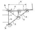
図1は、この発明のコンクリート床版用型枠支持機構の実施の形態を示す断面図である。図1に示すように、少主桁橋Aは、一対の主桁1、1と、主桁1、1同士を連結する複数の横桁2とを有している。この発明のコンクリート床版用型枠支持機構は、少主桁橋Aの外側の張出し部に設置される張出し部のコンクリート床版用型枠支持機構Bと、一対の主桁1、1間に設置される主桁間のコンクリート床版用型枠支持機構Cを備えている。
【0013】
まず。張出し部のコンクリート床版用型枠支持機構Bについて説明する。図2は、張出し部のコンクリート床版用型枠支持機構を説明する断面図である。この発明の張出し部のコンクリート床版用型枠支持機構Bは、第1パイプサポート3と、ターンバックル4と、大引材(桁外受け梁)7と、第2パイプサポート5、6とを備えている。
【0014】
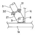
主桁1の下フランジ1aとウエブ1cとの付け根には、第1パイプサポート3の一端が支持されている。図3は、主桁の下フランジとウエブとの付け根C部と第1パイプサポートとの支持を説明する側面図、図4は正面図である。図3、4に示すように、第1パイプサポート3の一端にはジョイント金具21が、端部フランジ31及びボルト・ナット32によって固定されている。下フランジ1aとウエブ1cとの付け根C部には、ジョイント金具21を挿入可能な間隔の挿入部を有する端部金具8が溶接等によって取付けられている。ジョイント金具21は端部金具8に嵌め込まれ、ボルト・ナット9によって端部金具8に固定されている。かくして、主桁1の下フランジ1aとウエブ1cとの付け根に第1パイプサポート3の一端が支持され、ウエブ1c及び下フランジ1aに力が分散されるようになっている。
【0015】
主桁1の上フランジ1bとウエブ1cとの付け根には、ターンバックル4の一端が支持されている。図5は、主桁の上フランジとウエブとの付け根D部と、ターンバックル4との支持を説明する側面図である。図5に示すように、ターンバックル4の一端には引張り材22が設けられている。主桁1のウエブ1cには平板状の吊りピース45が設けられ、引張り材22は吊りピース45にボルト・ナット23により固定されている。
【0016】
主桁1の上フランジ1bの外側には、大引材(桁外受け梁)7が外側に張出して、ほぼ水平に近い状態でやや傾斜して設けられている。図6は、主桁の上フランジの外側E部における大引材の設置を示す側面図である。図6に示すように、主桁1の上フランジ1bには、吊りボルト用ナット24が吊りピース53を介して上フランジ1bからやや外側に張り出して溶接により固着されている。吊りボルト18は、極太材30を介して大引材7上に載置されているベニヤ板20を貫通して配され、その上端は吊りボルト用ナット24に螺合されている。上下の貫通孔(図示せず)を有する大引材7を、該貫通孔に吊りボルト18を挿入して配置し、大引材7の下方から突出している吊りボルト18に大引材固定ナット52を螺合し、ナット52の締め付けにより大引材7を固定する。19、19は、大引材7の上下を挟むプレートである。このようにして吊下げられた大引材7と上フランジ1bとの間の空間には角材50が配され、該空間の間隔を保っている。
【0017】
大引材7の中間部には第2パイプサポート5の一端が、該大引材7の先端部には第2パイプサポート6の一端が、それぞれ支持されている。図7は、大引材7の先端部と第2パイプサポート6の一端との支持部A部を説明する側面図である。図7に示すように、第2パイプサポート6の一端にはジョイント金具25が、端部フランジ33及びボルト・ナット34によって取付けられている。大引材7の先端部の下部には端部金具26が取付けられている。ジョイント金具25は、端部金具26にボルト・ナット27によって固定されている。第2パイプサポート5の一端と大引材7の中間部F部との支持構造も同様である。
【0018】
第2パイプサポート5及び6の他端と、第1パイプサポート3の他端と、ターンバックル4の他端とは、1箇所において結合されている。図8は、その結合部B部を示す側面図である。図8に示すように、第1パイプサポート3の他端と第2パイプサポート6の他端とは、ジョイント支柱28によって連結されている。ジョイント支柱28と第1パイプサポート3及び第2パイプサポート6とは、端部フランジ35およびボルト・ナット36によって固定されている。ジョイント支柱28にはガセットプレート29が一体となって固着されている。第2パイプサポート5の他端には2枚のジョイント金具37が端部フランジ38及びボルト・ナット39によって固定されており、ガセットプレート29の表裏両側に配された2枚のジョイント金具37は、ボルト・ナット40によってガセットプレート29に固定されている。更に、ターンバックル4の他端には引張り材41が設けられており、引張り材41はガセットプレート29にボルト・ナット42によって固定されている。かくして、第2パイプサポート5、6の他端と、第1パイプサポート3の他端と、ターンバックル4の他端とは1箇所(B部)で結合されている。
【0019】
上記のように、本発明のコンクリート床版用型枠支持機構は、チェーンよりも強度に優れるターンバックルを用いており、型枠支持機構の構成にチェーンを用いる従来のコンクリート床版用型枠支持機構よりも強度性において優れている。
【0020】
第1、第2パイプサポートの部材として既成のパイプを用いることができるので、材料費を節約することができる。リース品のパイプを使用することもできる。また、パイプは軽量であり、角材を用いる従来のコンクリート床版用型枠支持機構よりも重量を低減することができる。
【0021】
第1パイプサポートを主桁のフランジ部に直接溶接によって固定する方法では、主桁フランジ溶接部に力が集中してしまう問題があるが、本発明は、実施の形態に示すように、端部金具及びボルト・ナットを用いて固定することによりウエブ及びフランジに力を分散することができる。また、溶接による固定方法よりも作業性に優れている。
【0022】
また、本発明はチェーンにより作業や通行を妨げられることがない。すなわち、従来のコンクリート床版用型枠支持機構は、ターンバックルよりも強度が劣るチェーンによって型枠支持機構及び足場(朝顔)を支持する構成であり、非常に多数本のチェーンの配置が必要であるため、この多数本のチェーンが作業員の通行や作業の妨げとなっていた。これに対して、ターンバックルを用いる本発明は、図11に示すように、チェーンは足場を吊るためのみのものであり、従来の型枠支持機構よりも使用本数が大幅に減少する。図11は、この発明の張出し部のコンクリート床版用型枠支持機構の組立途中における足場の設置状況を示す断面図である。図11に示す実施例において足場44を吊るすチェーン43の使用本数は2本(片側)である。従って、作業員の通行や作業性に優れている。また、足場44の構造そのものも簡単である。
【0023】
図1では、以上説明した張出し部のコンクリート床版用型枠支持機構Bが、少主桁橋Aの両側の張出し部に設けられている。
【0024】
図9は、張出し部のコンクリート床版用型枠支持機構において、第2パイプサポートを1本用いた実施例である。少主桁橋の張出し長が短いときは、第2パイプサポートの本数を1本とすることができる。例えば、図2に示す張出し長Hの長さが3.5mであるとすると、図9に示すように張出し長hが2.0mである場合には、第2パイプサポート5の1本でよい。
【0025】
次に、主桁間のコンクリート床版用型枠支持機構Cについて説明する。
【0026】
図1に示すように、一対の主桁1、1には、一方側のコンクリート床版用型枠支持機構C1及び他方側のコンクリート床版用型枠支持機構C2が設置されている。コンクリート床版用型枠支持機構C1及びC2は、基本的に上述した張出し部のコンクリート床版用型枠支持機構Bと同様の構成を備えている。
【0027】
コンクリート床版用型枠支持機構C1は、第1パイプサポート13と、ターンバックル14と、大引材(桁内受け梁)17と、第2パイプサポート15、16とを備えている。主桁1の下フランジ1aとウエブ1cとの付け根c部には、第1パイプサポート13の一端が支持されている。c部の支持構造は、図3、4に示す張出し部のコンクリート床版用型枠支持機構BのC部と同様の構造を備える。
【0028】
主桁1の上フランジ1bとウエブ1cとの付け根d部には、ターンバックル14の一端が支持されている。d部の支持構造は、図5に示す、張出し部のコンクリート床版用型枠支持機構BのD部と同様の構造を備える。
【0029】
主桁1の上フランジ1bの内側e部には、大引材(桁内受け梁)17が水平に設けられている。e部における大引材17の設置構造は、図6に示す張出し部のコンクリート床版用型枠支持機構BのE部と同様の構造を備える。
【0030】
大引材17の中間部には第2パイプサポート15の一端が、該大引材17の先端部a部には第2パイプサポート16の一端が、それぞれ支持されている。a部における第2パイプサポート16の支持構造は、図7に示す張出し部のコンクリート床版用型枠支持機構BのA部と同様の構造を備える。また、第2パイプサポート15の一端と大引材17の中間部との支持構造も同様である。
【0031】
第2パイプサポート15、16の他端と、第1パイプサポート13の他端と、ターンバックル14の他端とは、1箇所の結合部b部において結合されている。結合部b部における支持構造は、図8に示す張出し部のコンクリート床版用型枠支持機構BのB部と同様の構造を備える。
【0032】
以上、一方側のコンクリート床版用型枠支持機構C1について説明したが、他方側の主桁1にも、一方側のコンクリート床版用型枠支持機構C1と同様の構成を有する、他方側のコンクリート床版用型枠支持機構C2が設置されている。
【0033】
図10は、主桁間のコンクリート床版用型枠支持機構の設置位置を説明する平面図である。本発明の主桁間のコンクリート床版用型枠支持機構Cは、図1に実線によって示されている一方側のコンクリート床版用型枠支持機構C1の設置位置と、破線によって示されている他方側のコンクリート床版用型枠支持機構C2の設置位置とが、橋軸方向に交互にずれている。ずなわち、図10に示すように、一方側のコンクリート床版用型枠支持機構C1と、他方側のコンクリート床版用型枠支持機構C2とが、少主桁橋Aの橋軸方向にずれて交互に配されている。
【0034】
このように、コンクリート床版用型枠支持機構C1とC2とが橋軸方向にずれて交互に配されている本願発明の主桁間のコンクリート床版用型枠支持機構は、型枠及びコンクリートを支持する支持機構の作用については従来のものと何ら変わるところはない。そして、主桁間隔が変化した場合でも、コンクリート床版用型枠支持機構C1とC2とはジャバラ式的に変化追従することができる。また、C1とC2とを分離したことによる部材重量の軽量化に伴い取り扱いが容易である。更に、C1とC2とを分離したことによる部材の組立解体の簡素化を図ることができる。
【0035】
なお、従来の主桁間のコンクリート床版用型枠支持機構は、この橋軸方向のずれはなく一直線状に配されており、このような従来の主桁間のコンクリート床版用型枠支持機構C1とC2とは、伸縮可能な間隔調整用装置を組み込んだ一体構造となっている。
【0036】
【実施例】
次に、この発明のコンクリート床版用型枠支持機構において、各構成部の好ましい実施例を図面を参照しながら説明する。
【0037】
[実施例1]
図12は、張出し部のコンクリート床版用型枠支持機構Bについて、主桁の上フランジの外側D、E部(図2参照)における大引材の設置構造の実施例を示す側面図、図13は平面図である。図12、13に示すように、主桁1の上フランジ1bの端部の上面には、段付きの大引材吊りピース47が上フランジ1bからやや外側に張り出して溶接により固着されている。上フランジ1bの端部の下面には、吊りボルト及びスペーサー用ナット48がナット用吊りピース51を介して上フランジ1bからやや外側に張り出して溶接により固着されている。ナット48の雌ねじは吊りボルト46の雄ねじと螺合可能となっている。吊りボルト46を、ナット48に螺合して回転し(ねじ込み)、ナット48の上方に突出した吊りボルト46の上端を吊りピース47に当接することにより、吊りボルト46が上フランジ1bに固定される。大引材7の端部には、主桁ウエブ1c側に開放された溝49(図13参照)が設けられている。ナット48の下部において平座金58を吊りボルト46に所定枚数嵌め込み、大引材7を移動して溝49内に吊りボルト46を挿入し、かくして、大引材7を上下に貫通して大引材7の下方に突出した吊りボルト46に大引材固定用ナット59を螺合し、ナット59の締め付けにより大引材7を固定する。ナット48及び平座金58がスペーサーとして作用し、上フランジ1bと大引材7との間の間隔を保持する。このため、図6に示すような角材50は使用されていない。
【0038】
本実施例において、スペーサー(吊りボルト及びスペーサー用ナット、及び、平座金)を用いる利点は下記のとおりである。すなわち、少主桁橋においては、主桁1の上フランジ1bの厚さが橋の長手方向の位置によって異なり、橋の長手方向中央部では厚く、橋の端部では中央部よりも薄くなっている。従って、大引材7の高さを一定にするためには、上フランジ1bと大引材7との間の間隔も橋の長手方向位置で上フランジ1bの厚さに応じて変えなければならない。本実施例によれば、上フランジ1bの厚さに応じて、すなわち橋の長手方向位置によりスペーサーの全長(高さ)を平座金58の枚数によって調整できるので、橋の長手方向のどの位置においても大引材7の高さを一定に保持することができる。なお、本実施例は、主桁間のコンクリート床版用型枠支持機構にも適用可能である。
【0039】
[実施例2]
図12、13に示すように、大引材(桁外受け梁)7と主桁1のウエブ1cとの間の隙間には、ターンバックル(補強部材)54が配されている。ターンバックル54は両端に環状部を備えている。ターンバックル54の一端は、主桁のウエブ1cに設けられた吊りピース45(図5参照)にボルト・ナット55により固定されている。一方、ターンバックル54の他端には、大引材7に貫通孔を介して水平に配された差込みピン56が挿入されている。57は、差込みピン56用の抜け止めピンである。このようにして、ターンバックル54によって大引材7と主桁1のウエブ1cとを結合することにより、吊りボルト46の移動が阻止される。補強部材として、羽子板方式による補強手段等を用いてもよい。
【0040】
本実施例において、ターンバックル(補強部材)を用いる利点は下記の通りである。すなわち、少主桁橋においては、橋に荷重がかかると大引材7が撓む現象が生じ、大引材7の撓みにより吊りボルト46が動いてしまう。吊りボルト46が動くと、上フランジ1bやベニヤ板20上において吊りボルト46の取り付け部に隙間が生じ、液状のコンクリート・モルタル(モルタル汁)が該隙間から落下し、下方における作業に大きな障害となる。本実施例によれば、ターンバックル54によって吊りボルト46の動きが阻止され、コンクリート・モルタルの落下が防止される。
【0041】
なお、図12においては、ターンバックル54とターンバックル4(引張り材22)とが別々の位置において吊りピース45に固定されているが、ターンバックル54及び4(引張り材22)を同じ位置で同じ孔により固定することもできる。これにより、1つの孔を共用できる。なお、この場合には、ターンバックル54と4(引張り材22)とを平板状の吊りピース45の表側と裏側に分けて配置すればよい。なお、本実施例は、主桁間のコンクリート床版用型枠支持機構にも適用可能である。
【0042】
[実施例3]
図14、15は、張出し部のコンクリート床版用型枠支持機構Bについて、第1パイプサポートの他端と第2パイプサポートの他端とターンバックルの他端との結合部B部(図8参照)の実施例を示す側面図である。図14は、第2パイプサポート6を鞘管60に挿入後の状態、図15は、挿入前の状態である。本実施例においては、第2パイプサポート6と、ジョイント支柱28との取り付け手段が、図8に示す結合部B部と異なっている。ジョイント支柱28の第2パイプサポート取付部には、第2パイプサポート6の内径よりもやや小さい外径を有する鞘管60が、ジョイント支柱28と同軸に溶接により取り付けられている。端部フランジ35にはピン孔(図示せず)が設けられている。第2パイプサポート6を鞘管60に挿入する。挿入後、端部フランジ35に設けたピン孔に安全のため横ぶれを防ぐピン61を差込む。第2パイプサポート6には、ジョイント支柱28に対する押付力が働くので、第2パイプサポート6はジョイント支柱28に不動に確保される。本実施例によれば、結合部B部の施工性が向上する。なお、本実施例は、主桁間のコンクリート床版用型枠支持機構にも適用可能である。
【0043】
【発明の効果】
以上説明したように、この発明によれば、下記に示す有用な効果がもたらされる。
(1)パイプサポートを用いることにより従来用いられた角材を用いるよりも部材の重量を低減することができる。パイプは、既成のパイプを用いることができ、また、リース品を用いることもできるため材料費を節約することができ、経済的に有利である。
(2)チェーンよりも強度に優れるターンバックルを用いる構成であり、チェーンを用いる従来のコンクリート床版用型枠支持機構よりも強度性において優れている。
(3)ターンバックルを用いることにより、チェーンは足場を吊るためにのみ用いられ、従来のように多数本のチェーンが現場に配置されることがなく、チェーンにより作業員の通行や作業が妨げられることがなく作業効率が向上する。
(4)主桁間のコンクリート床版用型枠支持機構においては、一方側と他方側のコンクリート床版用型枠支持機構C1とC2とが橋軸方向にずれて交互に配されているので、C1とC2とがジャバラ式的に変化追従し、部材重量が軽量化し、部材の組立解体の簡素化を図ることができる。
(5)大引材を吊り下げる吊りボルトを、大引材と主桁の上フランジとの間に設けたナット及び平座金により全長を変化可能なスペーサー介して吊下げたことにより、橋の長手方向のどの位置においても大引材の高さを一定に保持することができる。
(6)大引材を補強部材(ターンバックル)によって主桁のウエブに結合することにより、吊りボルトの動きを防止でき、液状のコンクリート・モルタルの落下を防止することができる。
【図面の簡単な説明】
【図1】この発明の実施の形態に係るコンクリート床版用型枠支持機構を示す断面図である。
【図2】この発明の実施の形態に係る張出し部のコンクリート床版用型枠支持機構を示す断面図である。
【図3】この発明の実施の形態に係る主桁の下フランジとウエブとの付け根C部と第1パイプサポートとの支持を説明する側面図である。
【図4】この発明の実施の形態に係る主桁の下フランジとウエブとの付け根C部と第1パイプサポートとの支持を説明する正面図である。
【図5】この発明の実施の形態に係る主桁の上フランジとウエブとの付け根D部とターンバックルとの支持を説明する側面図である。
【図6】この発明の実施の形態に係る主桁の上フランジの外側E部における大引材の設置を説明する側面図である。
【図7】この発明の実施の形態に係る大引材の先端部と第2パイプサポートの一端との支持部A部を示す側面図である。
【図8】この発明の実施の形態に係る第1パイプサポートの他端と第2パイプサポートの他端とターンバックルの他端との結合部B部を示す側面図である。
【図9】この発明の実施の形態に係る第2パイプサポートを1本用いた張出し部のコンクリート床版用型枠支持機構を示す断面図である。
【図10】この発明の実施の形態に係る主桁間のコンクリート床版用型枠支持機構の設置位置を説明する平面図である。
【図11】この発明の張出し部のコンクリート床版用型枠支持機構の組立途中における足場の設置状況を示す断面図である。
【図12】この発明の実施例に係る主桁の上フランジの外側D、E部における大引材の設置を説明する側面図である。
【図13】この発明の実施例に係る主桁の上フランジの外側D、E部における大引材の設置を説明する平面図である。
【図14】この発明の実施例に係る第1パイプサポートの他端と第2パイプサポートの他端とターンバックルの他端との結合部B部において第2パイプサポートを鞘管に挿入後の状態を示す側面図である。
【図15】この発明の実施例に係る第1パイプサポートの他端と第2パイプサポートの他端とターンバックルの他端との結合部B部において第2パイプサポートを鞘管に挿入する前の状態を示す側面図である。
【符号の説明】
A 少主桁橋
B 張出し部のコンクリート床版用型枠支持機構
C 主桁間のコンクリート床版用型枠支持機構
C1 主桁間の一方側のコンクリート床版用型枠支持機構
C2 主桁間の他方側のコンクリート床版用型枠支持機構
1 主桁
1a 下フランジ
1b 上フランジ
1c ウエブ
2 横桁
3 第1パイプサポート
4 ターンバックル
5 第2パイプサポート
6 第2パイプサポート
7 大引材(桁外受け梁)
8 端部金具
9 ボルト・ナット
13 第1パイプサポート
14 ターンバックル
15 第2パイプサポート
16 第2パイプサポート
17 大引材(桁内受け梁)
18 吊りボルト
19 プレート
20 ベニヤ板
21 ジョイント金具
22 引張り材
23 ボルト・ナット
24 吊りボルト用ナット
25 ジョイント金具
26 端部金具
27 ボルト・ナット
28 ジョイント支柱
29 ガセットプレート
30 極太材
31 端部フランジ
32 ボルト・ナット
33 端部フランジ
34 ボルト・ナット
35 端部フランジ
36 ボルト・ナット
37 ジョイント金具[0001]
BACKGROUND OF THE INVENTION
The present invention relates to a formwork support mechanism for a concrete floor slab for installing a concrete formwork for placing concrete in a bridge having a concrete floor slab, particularly a small main girder bridge.
[0002]
[Prior art]
In recent years, small-main girder bridges have been implemented in response to requests for improvement in economic efficiency, durability, labor-saving construction, and shortening the construction period for bridge construction.
[0003]
[Problems to be solved by the invention]
The small main girder bridge has a large main girder spacing and overhang, so it is said that the relationship between the fixed form frame support mechanism and the scaffolding is difficult.
[0004]
An object of the present invention is to provide a concrete floor slab form support mechanism that can increase the rigidity of the mechanism using a simple member, is easy to install and remove, and is economically advantageous.
[0005]
[Means for Solving the Problems]
(1) A formwork support mechanism for a concrete floor slab according to the present invention includes a pair of main girders that support a concrete floor slab and a plurality of cross girders that connect the main girders to the outside of a small main girder bridge. In a formwork support mechanism for a concrete floor slab installed between an overhang part or a pair of main girders, a large pulling material provided to be overhanged from the upper flange of the main girders, and one end joined to the large pulling material, The other end is joined to the base of the lower flange of the main girder and the web and the pipe support member that supports the large pulling material, one end is joined to the base of the upper flange of the main girder and the web, and the other end is joined A turnbuckle joined to the pipe support member side to support the pipe support member,
The pipe support member includes a first pipe support having one end joined to the base of the lower flange of the main girder and a web, and one or two second pipe supports having one end joined to the large pulling material. The other end of the turnbuckle is joined to the joint member, and the first pipe support, the second pipe support and the turnbuckle are joined at one place,
The joint member includes a joint column connecting the first pipe support and the second pipe support, and a gusset plate fixed to the joint column and joined to the other end of the turnbuckle. It is characterized by this.
[0006]
(2) Moreover, the formwork support mechanism for concrete floor slabs according to the present invention is a small main girder bridge having a pair of main girders that support the concrete floor slabs and a plurality of transverse girders that connect the main girders. In the concrete floor slab formwork support mechanism between the main girders installed between the pair of main girders, a plurality of concrete floor slab formwork supports on one side of the pair of main girders in the bridge axis direction A mechanism is arranged, and a plurality of other concrete floor slab formwork support mechanisms are arranged in the bridge axis direction on the other side of the pair of main girders,
These one-side concrete floor slab formwork support mechanism and the above-mentioned other concrete floor slab formwork support mechanism are alternately arranged shifted in the bridge axis direction,
The formwork support mechanism for a concrete floor slab includes a large-drawn material that extends from an upper flange of a main girder, one end joined to the large-drawn material, and the other end between the lower flange and the web of the main girder. A pipe support member joined to the base and supporting the beam receiving beam; one end is joined to the base of the upper flange of the main girder and the web; the other end is joined to the pipe support member side and the pipe support A turnbuckle for supporting the member,
The pipe support member includes a first pipe support having one end joined to the base of the lower flange of the main girder and a web, and one or two second pipe supports having one end joined to the large pulling material. The other end of the turnbuckle is joined to the joint member, and the first pipe support, the second pipe support and the turnbuckle are joined at one place,
The joint member includes a joint column connecting the first pipe support and the second pipe support, and a gusset plate fixed to the joint column and joined to the other end of the turnbuckle. It is characterized by this.
[0007]
(3) In the above (1) or (2), A sheath pipe that can be inserted into the second pipe support is provided at the second pipe support mounting portion of the joint column. .
[0008]
(4) Moreover, in the thing in any one of said (1)-(3), the reinforcement member is distribute | arranged between the large drawing material and the web of the main girder, and one end of the reinforcement member is the above-mentioned The other end of the main girder web At the end of the main beam side in the large pull material , Each of which is combined.
[0009]
(5) Moreover, the formwork support mechanism for a concrete floor slab according to the present invention is a small main girder bridge having a pair of main girders that support the concrete floor slab and a plurality of cross girders that connect the main girders. In the formwork support mechanism for concrete floor slabs installed between the outer overhang or the pair of main girders,
Having a large pulling material provided protruding from the upper flange of the main girder, The end of the large pulling material and the main girder flange are joined by a suspension bolt and the end of the large drawing material and the main girder joined by the suspension bolt The web is connected by a reinforcing member.
[0011]
DETAILED DESCRIPTION OF THE INVENTION
Next, embodiments of the present invention will be described with reference to the drawings.
[0012]
FIG. 1 is a sectional view showing an embodiment of a concrete floor slab form support mechanism of the present invention. As illustrated in FIG. 1, the small main girder bridge A includes a pair of main girders 1 and 1 and a plurality of
[0013]
First. The formwork support mechanism B for the concrete floor slab at the overhang portion will be described. FIG. 2 is a cross-sectional view for explaining the concrete floor slab form support mechanism of the overhanging portion. The concrete floor slab formwork support mechanism B of the overhanging portion of the present invention comprises a
[0014]
One end of the
[0015]
One end of the
[0016]
On the outer side of the
[0017]
One end of the
[0018]
The other ends of the second pipe supports 5 and 6, the other end of the
[0019]
As described above, the formwork support mechanism for a concrete floor slab according to the present invention uses a turnbuckle that is superior in strength to a chain, and a conventional formwork support for a concrete floor slab that uses a chain as the structure of the formwork support mechanism. It is superior in strength than the mechanism.
[0020]
Since an existing pipe can be used as a member of the first and second pipe supports, material costs can be saved. Lease pipes can also be used. Further, the pipe is lightweight and can be reduced in weight as compared with a conventional formwork support mechanism for concrete floor slabs using square bars.
[0021]
In the method of fixing the first pipe support directly to the flange portion of the main girder by welding, there is a problem that the force concentrates on the main girder flange weld portion. By fixing with metal fittings and bolts and nuts, the force can be distributed to the web and flange. Moreover, it is more workable than the fixing method by welding.
[0022]
Further, the present invention does not hinder work and traffic by the chain. That is, the conventional formwork support mechanism for concrete floor slabs is configured to support the formwork support mechanism and the scaffold (morning glory) with a chain that is inferior in strength to the turnbuckle, and it is necessary to arrange a very large number of chains. For this reason, this large number of chains hindered workers' traffic and work. On the other hand, as shown in FIG. 11, in the present invention using the turnbuckle, the chain is only used to suspend a scaffold, and the number of use is greatly reduced as compared with the conventional formwork support mechanism. FIG. 11 is a cross-sectional view showing the installation state of the scaffold during the assembly of the concrete floor slab form support mechanism of the overhang portion of the present invention. In the embodiment shown in FIG. 11, the number of
[0023]
In FIG. 1, the concrete floor slab formwork support mechanism B for the overhang portion described above is provided on the overhang portions on both sides of the small main girder bridge A.
[0024]
FIG. 9 shows an embodiment in which one second pipe support is used in the formwork support mechanism for a concrete floor slab at the overhang portion. When the extension length of the small main girder bridge is short, the number of second pipe supports can be one. For example, if the length of the overhang length H shown in FIG. 2 is 3.5 m, if the overhang length h is 2.0 m as shown in FIG. 9, one of the second pipe supports 5 may be used. .
[0025]
Next, the concrete floor slab form support mechanism C between the main girders will be described.
[0026]
As shown in FIG. 1, a pair of main girders 1 and 1 are provided with a concrete floor slab form support mechanism C <b> 1 on one side and a form support mechanism C <b> 2 for concrete floor slab on the other side. The concrete floor slab formwork support mechanisms C1 and C2 basically have the same configuration as the above-described concrete floor slab formwork support mechanism B of the overhang portion.
[0027]
The formwork support mechanism C1 for the concrete floor slab includes a
[0028]
One end of the
[0029]
A large pulling material (intra-girder receiving beam) 17 is horizontally provided on the inner side e of the
[0030]
One end of the second pipe support 15 is supported on the middle portion of the large pulling material 17, and one end of the
[0031]
The other ends of the second pipe supports 15 and 16, the other end of the
[0032]
As described above, the form support mechanism C1 for the concrete floor slab on one side has been described. The main girder 1 on the other side also has the same configuration as the form support mechanism C1 for the concrete floor slab on the other side. A concrete floor slab form support mechanism C2 is installed.
[0033]
FIG. 10 is a plan view for explaining the installation position of the concrete floor slab form support mechanism between the main girders. The concrete floor slab formwork support mechanism C between the main girders of the present invention is indicated by the broken line and the installation position of the concrete floor slab formwork support mechanism C1 on one side shown in FIG. The installation position of the form support mechanism C2 for the concrete floor slab on the other side is alternately shifted in the bridge axis direction. That is, as shown in FIG. 10, a concrete floor slab form support mechanism C1 on one side and a form support mechanism C2 on the other side concrete floor slab are arranged in the direction of the bridge axis of the small main girder bridge A. They are staggered alternately.
[0034]
As described above, the concrete floor slab form support mechanisms C1 and C2 are alternately arranged in the bridge axis direction, and the concrete floor slab form support mechanism between the main girders of the present invention includes a mold and a concrete. There is no difference from the conventional one in terms of the action of the support mechanism for supporting the. Even when the main girder interval changes, the concrete floor slab form support mechanisms C1 and C2 can follow the change in a bellows manner. In addition, handling is easy as the weight of the member is reduced by separating C1 and C2. Furthermore, it is possible to simplify the assembly and disassembly of the members by separating C1 and C2.
[0035]
The conventional formwork support system for concrete floor slabs between the main girders is arranged in a straight line without any deviation in the direction of the bridge axis. The mechanisms C1 and C2 have an integrated structure in which a space adjusting device that can be expanded and contracted is incorporated.
[0036]
【Example】
Next, in the concrete floor slab form support mechanism of the present invention, a preferred embodiment of each component will be described with reference to the drawings.
[0037]
[Example 1]
FIG. 12 is a side view showing an embodiment of an installation structure of a large pulling material in the outer side D, E (see FIG. 2) of the upper flange of the main girder for the concrete floor slab formwork support mechanism B of the overhanging part. 13 is a plan view. As shown in FIGS. 12 and 13, a stepped large pulling
[0038]
In this embodiment, the advantages of using spacers (suspending bolts, spacer nuts, and plain washers) are as follows. That is, in the small main girder bridge, the thickness of the
[0039]
[Example 2]
As shown in FIGS. 12 and 13, a turnbuckle (reinforcing member) 54 is disposed in a gap between the large pulling material (outer beam receiving beam) 7 and the
[0040]
In this embodiment, advantages of using a turnbuckle (reinforcing member) are as follows. That is, in a small main girder bridge, when a load is applied to the bridge, a phenomenon that the large pulling
[0041]
In FIG. 12, the
[0042]
[Example 3]
FIGS. 14 and 15 show a joint B portion of the other end of the first pipe support, the other end of the second pipe support, and the other end of the turnbuckle (FIG. 8). FIG. FIG. 14 shows a state after the
[0043]
【The invention's effect】
As described above, according to the present invention, the following useful effects are brought about.
(1) By using the pipe support, the weight of the member can be reduced as compared with the conventionally used square bar. As the pipe, an existing pipe can be used, and a leased product can also be used. Therefore, material costs can be saved, which is economically advantageous.
(2) The structure uses a turnbuckle that is superior in strength to the chain, and is superior in strength to a conventional concrete floor formwork support mechanism using a chain.
(3) By using the turnbuckle, the chain is used only to suspend the scaffolding, and a large number of chains are not arranged at the site as in the past, and the passage of workers and work is hindered by the chain. Work efficiency is improved.
(4) In the concrete floor slab formwork support mechanism between the main girders, the concrete floor slab formwork support mechanisms C1 and C2 on one side and the other side are alternately arranged shifted in the bridge axis direction. , C1 and C2 follow a bellows-like change, the weight of the member is reduced, and the assembly / disassembly of the member can be simplified.
(5) The length of the bridge is improved by suspending the suspension bolt that suspends the large pulling material through a spacer that can be changed in overall length by a nut and a flat washer provided between the large pulling material and the upper flange of the main girder. The height of the large pulling material can be kept constant at any position in the direction.
(6) By connecting the large pulling material to the web of the main girder by a reinforcing member (turn buckle), the movement of the suspension bolt can be prevented and the fall of the liquid concrete mortar can be prevented.
[Brief description of the drawings]
FIG. 1 is a cross-sectional view showing a formwork support mechanism for a concrete floor slab according to an embodiment of the present invention.
FIG. 2 is a cross-sectional view showing a concrete floor slab form support mechanism for an overhang portion according to an embodiment of the present invention.
FIG. 3 is a side view for explaining the support of the base C portion of the lower flange of the main girder and the web and the first pipe support according to the embodiment of the present invention.
FIG. 4 is a front view for explaining support of the base C portion of the lower flange of the main girder and the web and the first pipe support according to the embodiment of the present invention.
FIG. 5 is a side view for explaining the support of the base D portion of the upper flange of the main girder and the web and the turnbuckle according to the embodiment of the present invention.
FIG. 6 is a side view for explaining the installation of a large pulling material at the outer side E portion of the upper flange of the main girder according to the embodiment of the present invention.
FIG. 7 is a side view showing a support portion A portion between a front end portion of a large pulling material and one end of a second pipe support according to the embodiment of the present invention.
FIG. 8 is a side view showing a joint B portion of the other end of the first pipe support, the other end of the second pipe support, and the other end of the turnbuckle according to the embodiment of the present invention.
FIG. 9 is a cross-sectional view showing a formwork support mechanism for a concrete floor slab of an overhang portion using one second pipe support according to an embodiment of the present invention.
FIG. 10 is a plan view for explaining an installation position of a concrete floor slab form support mechanism between main girders according to the embodiment of the present invention.
FIG. 11 is a cross-sectional view showing a scaffold installation state during the assembly of the concrete floor slab formwork support mechanism of the overhang portion according to the present invention.
FIG. 12 is a side view for explaining the installation of the large pulling material at the outer side D, E part of the upper flange of the main girder according to the embodiment of the present invention.
FIG. 13 is a plan view for explaining the installation of a large drawing material at the outer side D, E of the upper flange of the main girder according to the embodiment of the present invention.
FIG. 14 shows a state after the second pipe support is inserted into the sheath pipe at a joint B part between the other end of the first pipe support, the other end of the second pipe support, and the other end of the turnbuckle according to the embodiment of the present invention; It is a side view which shows a state.
FIG. 15 shows a state before the second pipe support is inserted into the sheath tube at a connection part B between the other end of the first pipe support, the other end of the second pipe support, and the other end of the turnbuckle according to the embodiment of the present invention; It is a side view which shows the state.
[Explanation of symbols]
A small main girder bridge
B Formwork support mechanism for concrete floor slab at overhang
C Formwork support mechanism for concrete slabs between main girders
C1 Form support mechanism for concrete floor slabs on one side between main girders
C2 Form support mechanism for concrete floor slab on the other side between main girders
1 Main digit
1a Lower flange
1b Upper flange
1c web
2 horizontal girder
3 First pipe support
4 Turnbuckle
5 Second pipe support
6 Second pipe support
7 Large pulling material (outer girder beam)
8 End fitting
9 Bolts and nuts
13 First pipe support
14 Turnbuckle
15 Second pipe support
16 Second pipe support
17 Large pulling material (beams in girders)
18 Hanging bolt
19 plates
20 plywood
21 Joint bracket
22 Tensile material
23 Bolts and nuts
24 Nuts for suspension bolts
25 Joint bracket
26 End fitting
27 Bolts and nuts
28 Joint support
29 Gusset plate
30 Very thick wood
31 End flange
32 bolts and nuts
33 End flange
34 Bolts and nuts
35 End flange
36 Bolts and nuts
37 Joint bracket
Claims (5)
前記主桁の上フランジから張出して設けられた大引材と、
該大引材に一端が接合され、他端が前記主桁の下フランジとウエブとの付け根に接合されて前記大引材を支持するパイプサポート部材と、
一端が前記主桁の上フランジとウエブとの付け根に接合され、他端が前記パイプサポート部材側に接合されて該パイプサーポート部材を支持するターンバックルと、を備え、
前記パイプサポート部材は、一端が前記主桁の下フランジとウエブとの付け根に接合された第1パイプサポートと一端が前記大引材に接合された1本又は2本の第2パイプサポートをジョイント部材で連結してなると共に、前記ターンバックルの他端が該ジョイント部材に接合されて、第1パイプサポート、第2パイプサポート及びターンバックルが1箇所において結合されており、
前記ジョイント部材は、第1パイプサポートと第2パイプサポートを連結するジョイント支柱と、該ジョイント支柱に固着されてターンバックルの他端が接合されるガセットプレートを備えてなることを特徴とするコンクリート床版用型枠支持機構。For concrete floor slabs installed between an overhanging portion of a small main girder bridge or a pair of main girders having a pair of main girders that support the concrete slabs and a plurality of transverse girders that connect the main girders In the formwork support mechanism,
A large pulling material provided protruding from the upper flange of the main girder,
A pipe support member, one end of which is joined to the large pulling material, and the other end of which is joined to the base of the lower flange of the main girder and the web to support the large pulling material;
A turnbuckle that has one end joined to the base of the upper flange of the main girder and the web and the other end joined to the pipe support member side to support the pipe support member;
The pipe support member includes a first pipe support having one end joined to the base of the lower flange of the main girder and a web, and one or two second pipe supports having one end joined to the large pulling material. The other end of the turnbuckle is joined to the joint member, and the first pipe support, the second pipe support and the turnbuckle are joined at one place,
The joint member comprises a joint column for connecting the first pipe support and the second pipe support, and a gusset plate fixed to the joint column and joined to the other end of the turnbuckle. Plate formwork support mechanism.
前記一対の主桁の一方側に橋軸方向に複数の一方側のコンクリート床版用型枠支持機構を配し、前記一対の主桁の他方側に橋軸方向に複数の他方側のコンクリート床版用型枠支持機構を配し、
これら一方側のコンクリート床版用型枠支持機構と前記他方側のコンクリート床版用型枠支持機構とが、橋軸方向にずれて交互に配されており、
前記コンクリート床版用型枠支持機構は、主桁の上フランジから張出して設けられた大引材と、
該大引材に一端が接合され、他端が前記主桁の下フランジとウエブとの付け根に接合されて前記桁外受け梁を支持するパイプサポート部材と、
一端が前記主桁の上フランジとウエブとの付け根に接合され、他端が前記パイプサポート部材側に接合されて該パイプサーポート部材を支持するターンバックルと、を備え、
前記パイプサポート部材は、一端が前記主桁の下フランジとウエブとの付け根に接合された第1パイプサポートと一端が前記大引材に接合された1本又は2本の第2パイプサポートをジョイント部材で連結してなると共に、前記ターンバックルの他端が該ジョイント部材に接合されて、第1パイプサポート、第2パイプサポート及びターンバックルが1箇所において結合されており、
前記ジョイント部材は、第1パイプサポートと第2パイプサポートを連結するジョイント支柱と、該ジョイント支柱に固着されてターンバックルの他端が接合されるガセットプレートを備えてなることを特徴とするコンクリート床版用型枠支持機構。For a concrete floor slab between main girder installed between a pair of main girder of a small main girder bridge having a pair of main girder supporting a concrete floor slab and a plurality of horizontal girder connecting the main girder In the formwork support mechanism,
A plurality of one-side concrete floor slab formwork support mechanisms are arranged on one side of the pair of main girders in the bridge axis direction, and a plurality of other concrete floors are arranged on the other side of the pair of main girders in the bridge axis direction. A formwork support mechanism for printing plates is arranged,
These one-side concrete floor slab formwork support mechanism and the above-mentioned other concrete floor slab formwork support mechanism are alternately arranged shifted in the bridge axis direction,
The concrete floor slab form support mechanism is a large pulling material provided to protrude from the upper flange of the main girder,
A pipe support member, one end of which is joined to the large pulling material, the other end of which is joined to the base of the lower flange and the web of the main girder to support the outer beam of the girder;
A turnbuckle that has one end joined to the base of the upper flange of the main girder and the web and the other end joined to the pipe support member side to support the pipe support member;
The pipe support member includes a first pipe support having one end joined to the base of the lower flange of the main girder and a web, and one or two second pipe supports having one end joined to the large pulling material. The other end of the turnbuckle is joined to the joint member, and the first pipe support, the second pipe support and the turnbuckle are joined at one place,
The joint member comprises a joint column for connecting the first pipe support and the second pipe support, and a gusset plate fixed to the joint column and joined to the other end of the turnbuckle. Plate formwork support mechanism.
前記主桁の上フランジから張出して設けられた大引材を有し、該大引材の端部と主桁フ ランジを吊りボルトで接合すると共に該吊りボルトで接合された前記大引材の端部と前記主桁のウエブとの間を補強部材によって結合したことを特徴とするコンクリート床版用型枠支持機構。For concrete floor slabs installed between an overhanging portion of a small main girder bridge or a pair of main girders having a pair of main girders that support the concrete slabs and a plurality of transverse girders that connect the main girders In the formwork support mechanism,
Has Obiki material provided by overhanging from the flange on the main beam, the Obiki material joined by the hanging Ri volts while bolted hanging ends and Shuketafu flange of said Obiki material A formwork support mechanism for a concrete floor slab , wherein an end portion and a web of the main girder are coupled by a reinforcing member.
Priority Applications (1)
| Application Number | Priority Date | Filing Date | Title |
|---|---|---|---|
| JP2000366709A JP3919443B2 (en) | 2000-12-01 | 2000-12-01 | Formwork support mechanism for concrete floor slabs |
Applications Claiming Priority (1)
| Application Number | Priority Date | Filing Date | Title |
|---|---|---|---|
| JP2000366709A JP3919443B2 (en) | 2000-12-01 | 2000-12-01 | Formwork support mechanism for concrete floor slabs |
Publications (3)
| Publication Number | Publication Date |
|---|---|
| JP2002167716A JP2002167716A (en) | 2002-06-11 |
| JP2002167716A5 JP2002167716A5 (en) | 2007-04-26 |
| JP3919443B2 true JP3919443B2 (en) | 2007-05-23 |
Family
ID=18837283
Family Applications (1)
| Application Number | Title | Priority Date | Filing Date |
|---|---|---|---|
| JP2000366709A Expired - Fee Related JP3919443B2 (en) | 2000-12-01 | 2000-12-01 | Formwork support mechanism for concrete floor slabs |
Country Status (1)
| Country | Link |
|---|---|
| JP (1) | JP3919443B2 (en) |
Families Citing this family (4)
| Publication number | Priority date | Publication date | Assignee | Title |
|---|---|---|---|---|
| JP3922455B2 (en) * | 2003-06-06 | 2007-05-30 | Jfe工建株式会社 | Formwork support mechanism, beam holding jig, floor slab placement method |
| JP4020406B2 (en) * | 2006-06-28 | 2007-12-12 | Jfe工建株式会社 | Formwork support mechanism and placement method |
| CN109024290A (en) * | 2018-08-01 | 2018-12-18 | 中铁十局集团第五工程有限公司 | A kind of bowl fastening type full framing and its construction method for continuous beam |
| CN110886231A (en) * | 2019-12-13 | 2020-03-17 | 中铁第四勘察设计院集团有限公司 | Construction method of bridge panel and supporting structure thereof |
-
2000
- 2000-12-01 JP JP2000366709A patent/JP3919443B2/en not_active Expired - Fee Related
Also Published As
| Publication number | Publication date |
|---|---|
| JP2002167716A (en) | 2002-06-11 |
Similar Documents
| Publication | Publication Date | Title |
|---|---|---|
| JP5020163B2 (en) | Support for overhanging slab | |
| KR101198812B1 (en) | composite rahmen bridge using a preflex girder | |
| KR100946940B1 (en) | Joint structure for steel column and flat slab | |
| JP2010065378A (en) | Hanging scaffold and method for erecting the same | |
| JP5020162B2 (en) | Support for overhanging slab | |
| KR20170027236A (en) | the rigid connection structure between precast concrete column and precast concrete girder and the rigid connection structure between precast concrete girder and precast concrete beam using the plate, the modular system using the same | |
| KR20120085641A (en) | Assembling structure for beam and slab and method for constructing cosstructure using it | |
| JP3919443B2 (en) | Formwork support mechanism for concrete floor slabs | |
| JP3737475B2 (en) | Box girder bridge structure and construction method | |
| KR101124515B1 (en) | Scaffolding structure using compositive section beam introducing prestress by maximizing rigidity and eccentricity by combination of various sections | |
| JP2967874B1 (en) | How to build an overhead suspension bridge | |
| KR102137126B1 (en) | aluminium truss bridge | |
| KR102342075B1 (en) | Connecting structure for steel cross-beam | |
| JP3032476B2 (en) | Moving device for floor slab formwork | |
| JP3798701B2 (en) | Steel girder bridge with concrete cross girder | |
| CN221422643U (en) | Cantilever formwork structure | |
| CN221422644U (en) | Cantilever formwork structure | |
| KR100840279B1 (en) | Suspension hanger for slab form | |
| JP2004197389A (en) | Flat slab structure | |
| KR20210004289A (en) | Transfer Structure Construction Method Using U-shaped Steel Girder | |
| KR20020065024A (en) | PCS beam fixing method | |
| KR102513956B1 (en) | Bracket structure for bridge construction | |
| JP3232630U (en) | Joining structure of mountain retaining material | |
| JP3833514B2 (en) | Formwork structure | |
| KR20130075136A (en) | Nonsupporting slab form |
Legal Events
| Date | Code | Title | Description |
|---|---|---|---|
| A80 | Written request to apply exceptions to lack of novelty of invention |
Free format text: JAPANESE INTERMEDIATE CODE: A80 Effective date: 20001201 |
|
| A621 | Written request for application examination |
Free format text: JAPANESE INTERMEDIATE CODE: A621 Effective date: 20060110 |
|
| A521 | Written amendment |
Free format text: JAPANESE INTERMEDIATE CODE: A523 Effective date: 20060719 |
|
| RD01 | Notification of change of attorney |
Free format text: JAPANESE INTERMEDIATE CODE: A7421 Effective date: 20060719 |
|
| A521 | Written amendment |
Free format text: JAPANESE INTERMEDIATE CODE: A523 Effective date: 20060804 |
|
| A521 | Written amendment |
Free format text: JAPANESE INTERMEDIATE CODE: A523 Effective date: 20060831 |
|
| A871 | Explanation of circumstances concerning accelerated examination |
Free format text: JAPANESE INTERMEDIATE CODE: A871 Effective date: 20060831 |
|
| A975 | Report on accelerated examination |
Free format text: JAPANESE INTERMEDIATE CODE: A971005 Effective date: 20060911 |
|
| A131 | Notification of reasons for refusal |
Free format text: JAPANESE INTERMEDIATE CODE: A131 Effective date: 20060919 |
|
| A521 | Written amendment |
Free format text: JAPANESE INTERMEDIATE CODE: A523 Effective date: 20061012 |
|
| TRDD | Decision of grant or rejection written | ||
| A01 | Written decision to grant a patent or to grant a registration (utility model) |
Free format text: JAPANESE INTERMEDIATE CODE: A01 Effective date: 20070213 |
|
| A61 | First payment of annual fees (during grant procedure) |
Free format text: JAPANESE INTERMEDIATE CODE: A61 Effective date: 20070213 |
|
| R150 | Certificate of patent or registration of utility model |
Free format text: JAPANESE INTERMEDIATE CODE: R150 |
|
| A521 | Written amendment |
Free format text: JAPANESE INTERMEDIATE CODE: A523 Effective date: 20061012 |
|
| S111 | Request for change of ownership or part of ownership |
Free format text: JAPANESE INTERMEDIATE CODE: R313115 |
|
| FPAY | Renewal fee payment (event date is renewal date of database) |
Free format text: PAYMENT UNTIL: 20100223 Year of fee payment: 3 |
|
| R371 | Transfer withdrawn |
Free format text: JAPANESE INTERMEDIATE CODE: R371 |
|
| S111 | Request for change of ownership or part of ownership |
Free format text: JAPANESE INTERMEDIATE CODE: R313115 |
|
| R371 | Transfer withdrawn |
Free format text: JAPANESE INTERMEDIATE CODE: R371 |
|
| FPAY | Renewal fee payment (event date is renewal date of database) |
Free format text: PAYMENT UNTIL: 20100223 Year of fee payment: 3 |
|
| FPAY | Renewal fee payment (event date is renewal date of database) |
Free format text: PAYMENT UNTIL: 20100223 Year of fee payment: 3 |
|
| S111 | Request for change of ownership or part of ownership |
Free format text: JAPANESE INTERMEDIATE CODE: R313111 |
|
| FPAY | Renewal fee payment (event date is renewal date of database) |
Free format text: PAYMENT UNTIL: 20100223 Year of fee payment: 3 |
|
| R360 | Written notification for declining of transfer of rights |
Free format text: JAPANESE INTERMEDIATE CODE: R360 |
|
| FPAY | Renewal fee payment (event date is renewal date of database) |
Free format text: PAYMENT UNTIL: 20100223 Year of fee payment: 3 |
|
| R370 | Written measure of declining of transfer procedure |
Free format text: JAPANESE INTERMEDIATE CODE: R370 |
|
| FPAY | Renewal fee payment (event date is renewal date of database) |
Free format text: PAYMENT UNTIL: 20110223 Year of fee payment: 4 |
|
| FPAY | Renewal fee payment (event date is renewal date of database) |
Free format text: PAYMENT UNTIL: 20110223 Year of fee payment: 4 |
|
| S111 | Request for change of ownership or part of ownership |
Free format text: JAPANESE INTERMEDIATE CODE: R313111 |
|
| FPAY | Renewal fee payment (event date is renewal date of database) |
Free format text: PAYMENT UNTIL: 20110223 Year of fee payment: 4 |
|
| R350 | Written notification of registration of transfer |
Free format text: JAPANESE INTERMEDIATE CODE: R350 |
|
| FPAY | Renewal fee payment (event date is renewal date of database) |
Free format text: PAYMENT UNTIL: 20110223 Year of fee payment: 4 |
|
| FPAY | Renewal fee payment (event date is renewal date of database) |
Free format text: PAYMENT UNTIL: 20120223 Year of fee payment: 5 |
|
| FPAY | Renewal fee payment (event date is renewal date of database) |
Free format text: PAYMENT UNTIL: 20120223 Year of fee payment: 5 |
|
| FPAY | Renewal fee payment (event date is renewal date of database) |
Free format text: PAYMENT UNTIL: 20130223 Year of fee payment: 6 |
|
| LAPS | Cancellation because of no payment of annual fees |