JP3918574B2 - Printing apparatus and printing method - Google Patents
Printing apparatus and printing method Download PDFInfo
- Publication number
- JP3918574B2 JP3918574B2 JP2002032706A JP2002032706A JP3918574B2 JP 3918574 B2 JP3918574 B2 JP 3918574B2 JP 2002032706 A JP2002032706 A JP 2002032706A JP 2002032706 A JP2002032706 A JP 2002032706A JP 3918574 B2 JP3918574 B2 JP 3918574B2
- Authority
- JP
- Japan
- Prior art keywords
- paper
- printing
- cutting
- cut
- printer
- Prior art date
- Legal status (The legal status is an assumption and is not a legal conclusion. Google has not performed a legal analysis and makes no representation as to the accuracy of the status listed.)
- Expired - Fee Related
Links
Images


Description
【0001】
【発明の属する技術分野】
本発明は、印刷装置に係り、特に、連続紙に余白なしで画像を印刷し、自動カットを行なう印刷装置に関する。
【0002】
【従来の技術】
近年、プリンタで、4辺余白なし印刷を実現するための技術開発が進められ、商品化されている。余白なし印刷では、図9に示すように、印刷すべき画像を拡大して、用紙サイズ701より少し大きなサイズの画像702を生成し、この拡大画像を印刷することにより4辺に余白が生じないようにしている。
【0003】
余白なし印刷は、主として、A4、B5等の定形のカット紙を対象に行なわれているが、ロール紙等の連続紙を対象にした余白なし印刷も実用化している。
【0004】
一方、ロール等の連続紙に印刷を行なうプリンタは、印刷後に指定されたサイズで自動的に用紙をカットするためのカッタを筐体内に備えるようにしているものがある。
【0005】
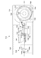
図10は、カッタを筐体内に備えたプリンタの印刷機構、紙送り機構およびカッティング機構を説明するためのプリンタ710の側断面概略図である。ここでは、印刷用紙として、ロール紙722を用いた場合を例に説明する。
【0006】
従来のカッティング機能付プリンタ710は、装置本体723と、ロール紙722がセットされたロール紙カセット724とを備えている。
【0007】
ロール紙722は、ドラム状の紙管727に対し、その軸部728に押通された状態で取着され、ロール紙カセット724の底部に配置された前後一対のローラ729、730に紙管727の鍔部731が載置された状態で収容される。ロール紙カセット724の底部後側には駆動ローラ730を駆動するロール紙モータ732が配設されている。ロール紙モータ32が正転駆動されると、駆動ローラ730から鍔部731に回転力が伝達されて、ロール紙722は用紙を繰り出す方向に回転する。一方、ロール紙モータ732が逆転駆動されると、駆動ローラ730から鍔部731に回転力が伝達されて、ロール紙722は用紙を巻き取る方向に回転する。
【0008】
ロール紙カセット724の前端部には、ロール紙722から送出されたロール紙722の搬送経路に相当する位置に給紙装置733が配設されている。給紙装置733は、給紙従動ローラ735と、給紙駆動ローラ736とを備え、ロール紙722を装置本体723側に送出する。装置本体723には、上流側から搬送ローラ737、排紙ローラ738が配置されている。
【0009】
装置本体723は、キャリッジ軸740を備え、このキャリッジ軸740にキャリッジ741が摺動可能に支持されている。キャリッジ741の下面には記録ヘッド743が取り付けられ、この記録ヘッド743のノズル孔(図示せず)からインク滴が吐出されてロール紙722に印刷が行なわれる。記録ヘッド743は、装置本体723と別体のインクカートリッジ(図示せず)に接続され、このインクカートリッジからインクの供給を受けている。また、紙送り方向において搬送ローラ737と排紙ローラ738との間には、プラテン39が配置されている。
【0010】
装置本体723には、印刷済みのロール紙722をカットするためのカッタ装置745が配置される。カッタ装置745は、ロール紙印刷の普及状況を考慮し、オプション的な位置づけとなっている。このため、ユーザが後から装着しやすいように筐体の外部付近に配置するようになっている。したがって記録ヘッド743より排紙側でカットがおこなわれることになる。
【0011】
カッタ装置745は、加工手段としてのカッタ746を備え、カッタ746は、可動刃746aが固定刃746bに切断可能に係合した状態でロール紙722の幅方向(紙送り方向と直交する方向)に移動することによりロール紙722を切断する。カッタ746によって切断されたロール紙722は、カッタ装置745の補助駆動ローラ748により装置本体23の外部に排出される。
【0012】
このようなカッティング機能付プリンタ710で、ロール紙等の連続紙に余白なし印刷を行なおうとする場合には、例えば、図11(a)に示すように、前後の画像を連続して印刷させ、その境界線でカットする方式が実用化されている(1回カット方式)。
【0013】
ところが、カットは機械的に行なうものであり、カット位置に誤差を伴うことから、画像が余白なしで連続している1回カット方式では、カット後の画像に前後の画像が入り込んでしまうおそれがある。例えば、前の画像が黒を基調とした画像で、後ろの画像が明るい色を基調とした画像の場合に、後ろの画像のカット位置に前の画像が入り込んで、黒線が目立ってしまう場合等である。
【0014】
このような前後の画像の入り込みが生じると、印刷結果の品質が低下してしまう。このため、ロール紙等の連続紙に余白なし印刷を行なうプリンタでは、必要に応じて、図11(b)に示すように、拡大した前後の画像の間に隙間を設けて印刷させ、それぞれの画像の少し内側をカットすることで、前後の画像の入り込みを防ぐことができるようにしている。
【0015】
【発明が解決しようとする課題】
ところが、拡大した前後の画像の間に隙間を設けて印刷させ、画像の少し内側をカットする方式(2回カット方式)によれば、画像と画像との間で2回カットする必要がある。カットする際には、いったん紙送りを停止させるため、本方法では印刷を2度中断する必要がある。
【0016】
このため、前後の画像の入り込みを防ぐ2回カット方式は、画像の入り込みを許容する1回カット方式に比べ、印刷の仕上がりまで時間が余計にかかることになる。
【0017】
さらに、前後の画像の入り込みを2回カット方式は画像と画像との間に切りくずが発生することになる。
【0018】
本発明の目的は、連続紙に対する余白なし印刷で前後の画像の入り込みを防ぐ印刷装置において印刷時間を短縮することにある。
【0019】
また、本発明の別目的は、連続紙に対する余白なし印刷で前後の画像の入り込みを防ぐ印刷装置において、切りくずを発生させないようにすることにある。
【0020】
【課題を解決するための手段】
上記課題を解決するため、本発明の第1の態様によれば、
連続紙供給機構と、連続紙切断機構と、印刷機構とを備えた連続紙に余白なし印刷を行なう印刷装置であって、
前記連続紙切断機構は、前記連続紙供給機構と前記印刷機構との間に配置されていることを特徴とする印刷装置が提供される。
【0021】
また、本発明の第2の態様によれば、
連続紙に余白なし印刷を行なう印刷装置であって、
仕上がりの用紙サイズに関する情報を受け付ける手段と、
仕上がりの用紙サイズになるように連続紙を切断する手段と、
仕上がりの用紙サイズに切断された連続紙に対して余白なし印刷を行なう手段とを備えることを特徴とする印刷装置が提供される。
【0022】
また、本発明の第3の態様によれば、
連続紙に余白なし印刷を行なう印刷装置であって、
仕上がりの用紙サイズに関する情報を受け付ける手段と、
仕上がりの用紙サイズになるように連続紙を切断する手段とを備え、
前記連続紙を切断する手段は、余白なし印刷が開始された後、まだ印刷が行なわれていない連続紙上の位置において切断を行なうことを特徴とする印刷装置が提供される。
【0023】
また、本発明の第4の態様によれば、
連続紙に余白なし印刷を行なう印刷方法であって、
仕上がりの用紙サイズ設定を受け付けるステップと、
仕上がりの用紙サイズになるように連続紙を切断するステップと、
仕上がりの用紙サイズに切断された連続紙に対して余白なし印刷を行なうステップとを備えることを特徴とする印刷方法が提供される。
【0024】
さらに、本発明の第5の態様によれば、
連続紙に余白なし印刷を行なう印刷方法であって、
仕上がりの用紙サイズに関する情報を受け付けるステップと、
余白なし印刷を開始後、まだ印刷が行なわれていない連続紙上の位置において、仕上がりの用紙サイズになるように連続紙を切断するステップとを備えることを特徴とする印刷方法が提供される。
【0025】
【発明の実施の形態】
本発明の実施の形態について図面を参照して説明する。
【0026】
図1は、本発明を適用した印刷システムのハードウェア構成の概要を説明するためのブロック図である。
【0027】
本図に示すように、印刷システムは、アプリケーションによる各種処理、プリンタドライバによる印刷処理等を実現するためのコンピュータ50と、このコンピュータ50に接続されるカッティング機能付プリンタ10(以下、単に「プリンタ10」とも記す)とを備えて構成される。本実施形態において、コンピュータ50は、印刷データを生成し、プリンタ10に送信するプリンタホストとして機能する。プリンタ10は、コンピュータ50から受信した印刷データに基づいて印刷を行なう。プリンタ10は、ロール紙等の印刷用紙に印刷を行ない、指定されたサイズにカットするためのカッティング機能を備えている。なお、印刷システムの構成はこれに限られない。例えば、コンピュータ50を複数台接続したネットワーク印刷システムとしてもよい。
【0028】
コンピュータ50は、各種プログラムに基づいて処理を行うCPU(Central Processing Unit)51、データおよびプログラム等を一時的に記憶するRAM(Random Access Memory)52、コンピュータ50を制御するための各種データ、起動時用プログラム等があらかじめ不揮発的に記憶されているROM(Read Only Memory)53、および、接続されたプリンタ10等の周辺装置とのデータの送受信をつかさどるインタフェース54を備えている。
【0029】
また、コンピュータ50には、カラーディスプレイ等の表示装置61、マウス、キーボード等の入力装置62、CD−ROM等の記録媒体からデータを読み取るメディア読取装置63、および、内蔵または外付けの補助記憶装置64が接続される。ただし、コンピュータ50の構成はこれに限られない。
【0030】
プリンタ10は、例えば、インクジェット方式のカラープリンタである。インクジェット方式のカラープリンタは、筐体内にインクを充填したインクカートリッジを複数備え、このインクを記録ヘッドから印刷用紙等の印刷媒体に吹き付けて印刷を行なう。ただし、プリンタ10の印刷方式はインクジェット方式に限られない。
【0031】
プリンタ10は、データの受信等、コンピュータ50との通信をつかさどるインタフェース11と、印刷データ、各種プログラム等に基づいて処理を行なうCPU12と、印刷データ等を一時的に記憶するRAM13と、プリンタ10を制御するための各種データ、各種プログラム等があらかじめ不揮発的に記憶されているROM14と、インクを吐出する印刷ヘッド、印刷ヘッドを搭載するキャリッジを駆動するキャリッジ駆動機構等からなる印刷機構15と、印刷用紙の給排紙を行なう紙送り機構16と、印刷用紙のカットを行なうカッティング機構17とを備えて構成される。ただし、プリンタ10の構成はこれに限られない。
【0032】
つぎに、本実施の形態で用いられるカッティング機能付プリンタ10の印刷機構15、紙送り機構16およびカッティング機構17の概略について説明する。ここでは、印刷用紙として、ロール紙22を用いた場合を例に説明する。もちろん、印刷機構15、紙送り機構16およびカッティング機構17は、定形用紙その他の印刷媒体に対して同様に機能することができる。
【0033】
図2は、印刷機構15、紙送り機構16およびカッティング機構17を説明するためのプリンタ10の側断面概略図である。カッティング機能付プリンタ10は、印刷用紙としてのロール紙22への印刷を行なう印刷機構15、印刷用紙の給紙を行なう紙送り機構16、印刷用紙のカットを行なうカッティング機構17等を有する装置本体23と、ロール紙22がセットされたロール紙カセット24とを備えている。なお、ロール紙以外の印刷用紙は、図示しない用紙トレイあるいは手差し挿入口等から供給するようにする。
【0034】
ロール紙22は、ドラム状の紙管27に対し、その軸部28に押通された状態で取着され、ロール紙カセット24の底部に配置された前後一対のローラ29、30に紙管27の鍔部31が載置された状態で収容される。ロール紙カセット24の底部後側には駆動ローラ30を駆動するロール紙モータ32が配設されている。ロール紙モータ32が正転駆動されると、駆動ローラ30から鍔部31に回転力が伝達されて、ロール紙22は用紙を繰り出す方向に回転する。一方、ロール紙モータ32が逆転駆動されると、駆動ローラ30から鍔部31に回転力が伝達されて、ロール紙22は用紙を巻き取る方向に回転する。
【0035】
ロール紙カセット24の前端部には、ロール紙22から送出されたロール紙22の搬送経路に相当する位置に給紙装置33が配設されている。給紙装置33は、給紙従動ローラ35と、給紙駆動ローラ36とを備え、ロール紙22を装置本体23側に送出する。装置本体23には、上流側から搬送ローラ37、排紙ローラ38が配置されている。主として、これらの部位が紙送り機構16を構成する。
【0036】
装置本体23は、キャリッジ軸40を備え、このキャリッジ軸40にキャリッジ41が摺動可能に支持されている。キャリッジ41の下面には記録ヘッド43が取り付けられ、この記録ヘッド43のノズル孔(図示せず)からインク滴が吐出されてロール紙22に印刷が行なわれる。記録ヘッド43は、装置本体23と別体のインクカートリッジ(図示せず)に接続され、このインクカートリッジからインクの供給を受けている。また、紙送り方向において搬送ローラ37と排紙ローラ38との間には、プラテン39が配置されている。主として、これらの部位が印刷機構15を構成する。
【0037】
装置本体23には、ロール紙22をカットするためのカッタ装置45が内蔵されている。カッタ装置45は、加工手段としてのカッタ46を備え、カッタ46は、可動刃46aが固定刃46bに切断可能に係合した状態でロール紙22の幅方向(紙送り方向と直交する方向)に移動することによりロール紙22を切断する。カッタ46によって切断されたロール紙22は、カッタ装置45の補助駆動ローラ48により印刷機構15側に送られる。主として、これらの部位がカッティング機構17を構成する。
【0038】
本実施形態では、ロール紙印刷の普及を鑑み、あらかじめカッタ装置45を標準的に内蔵することにより、印刷機構15より給紙側にカッタ装置45を配置するようにしている。したがって、記録ヘッド43による印刷の前に用紙22のカットが行なわれることになる。
【0039】
印刷機構15は、コンピュータ50から送られる印刷データ中の印刷コマンドをCPU12が実行することにより制御される。すなわち、コンピュータ50は、描画コマンドを含む印刷データをプリンタ10に送信することにより、任意の画像を任意の位置に印刷させることができる。
【0040】
紙送り機構16、カッティング機構17は、コンピュータ50から送られる印刷データ中のロール紙送りコマンド、カッティングコマンドをCPU12が実行することにより制御される。すなわち、コンピュータ50は、ロール紙送りコマンド、カッティングコマンドを含む印刷データをプリンタ10に送信することにより、プリンタ10に対して任意の量のロール紙送り(戻し)を行なわせ、任意の位置でカッティングを行なわせることができる。
【0041】
次に、上記印刷システムによりコンピュータ50およびプリンタ10に実現される機能構成について、図3のブロック図を参照して説明する。
【0042】
本図に示すように、コンピュータ50上には、アプリケーション510とプリンタドライバ520とが構築される。
【0043】
アプリケーション510は、ワードプロセッサ、グラフィックス等の処理をコンピュータ50に行なわせるための機能を有しており、RAM52が読み込んだアプリケーションプログラムを、CPU51が実行することによりコンピュータ50上に構築される。
【0044】
プリンタドライバ520は、ユーザからの指示に基づいて、アプリケーション510が生成した画像データを読み込んで、プリンタ10が解釈できる形式の印刷データに変換し、インタフェース54を介してプリンタ10に送信する機能を有している。
【0045】
このため、プリンタドライバ520は、アプリケーション510が生成した画像データをドットの集合体であるイメージデータに展開するラスタライザ処理と、イメージデータの色変換処理および中間調処理を行なうハーフトーン処理と、上記処理後のイメージデータをプリンタ10を制御するための印刷コマンドに変換するコマンド変換処理とを行なう印刷データ生成部522およびユーザから印刷条件の設定、印刷命令等を受け付けるユーザインタフェース部521を備えている。
【0046】
プリンタドライバ520は、RAM52が読み込んだプリンタドライバプログラムを、CPU51が実行することによりコンピュータ50上に構築される。このためのプリンタドライバプログラムは、例えば、CD−ROM等の可搬型の記録媒体に記録することで流通させることができる。そして、この記録媒体を、メディア読取装置63で読み取ることにより、コンピュータ50にプリンタドライバプログラムをインストールすることができる。また、例えば、インターネット等のコンピュータネットワークを介してインストールすることもできる。
【0047】
図3において、プリンタ10上には、印刷制御部110および印刷実行部120が構築される。
【0048】
印刷制御部110は、CPU12により実現され、コンピュータ50から送信された印刷データを解釈して、印刷データに基づく印刷をプリンタ10で実行するための制御を行なう。
【0049】
印刷実行部120は、印刷機構15、紙送り機構16およびカッティング機構17により実現され、印刷制御部110の指示にしたがって、印刷用紙に対する印刷を実行する。
【0050】
つぎに、本印刷システムにおける連続紙へ余白なし印刷時のカット処理について説明する。本実施形態では、給紙装置33と記録ヘッド43との間において用紙のカットを行なう。このとき、あらかじめ用紙を仕上がりのサイズにカットしておいてから記録ヘッド43による印刷を開始する方式(第1のカット方式)と、記録ヘッド43による印刷を開始後(印刷実行中)に仕上がりのサイズにカットして、印刷を続行する方式(第2のカット方式)とを選択的に行なうことができる。
【0051】
図4は、本処理におけるカッタ46と記録ヘッド43との距離Wおよびカット後の用紙縦幅Sとカット方式との関係について説明するための図である。このうち、距離Wは固定であるが、用紙縦幅Sは、仕上がりの用紙サイズに応じて可変である。
【0052】
図4(a)は、WがSより短い場合である。この場合は、第1のカット方式および第2のカット方式のいずれも行なうことができる。すなわち、第1のカット方式を採用したときには、まず、用紙22の先頭がカッタ46の位置からSの距離になるまで用紙22を送り、仕上がりのサイズになるようにカットを行なう。そして、用紙22の先頭が記録ヘッド43の位置になるまで用紙22を戻してから印刷を開始する。一方、第2のカット方式を採用したときは、用紙22の先頭が記録ヘッド43の位置から印刷を開始して用紙22を送っていき、カッタ46の位置に用紙22の先頭からSの箇所がきたときにカットを行なって、用紙を切り離した後、残りの印刷を続行する。
【0053】
図4(b)は、WがSより長い場合である。この場合は、第1のカット方式を採用する。すなわち、まず、用紙22の先頭がカッタ46の位置からSの距離になるまで用紙22を送り、仕上がりのサイズになるようにカットを行なう。そして、用紙22の先頭が記録ヘッド43の位置になるまで用紙22を送ってから印刷を開始する。
【0054】
なお、カッティング機能付きプリンタ10の設計上、Wの距離を十分短くするようにすれば、ほとんどの場合において図4(a)に示したパターンとなるため、第1のカット方式、第2のカット方式のいずれも採用することができる。
【0055】
プリンタドライバ520は、ユーザから受け付ける印刷条件の設定における用紙サイズあるいはその他の条件によって第1のカット方式および第2のカット方式のいずれを採用するかを決定する。ただし、あらかじめ第1のカット方式あるいは第2のカット方式に固定しておいてもよい。
【0056】
ここで、本実施形態におけるプリンタドライバ520の処理について図5のフロー図を参照して説明する。
【0057】
印刷実行に先立ち、プリンタドライバ520のユーザインタフェース部521は、ユーザから印刷条件の設定を受け付けることができる(S101)。なお、ユーザは印刷条件の設定を行なうことなく印刷を行なうことができるが、この場合は前回設定された印刷条件が引き継がれる。
【0058】
プリンタドライバ520のユーザインタフェース部521は、ユーザから、例えば、アプリケーション510のメニューコマンド等を介して、印刷条件設定の命令を受け付けると、図6に一例を示すような印刷条件設定画面300を表示装置61に表示して、ユーザから印刷条件の設定を受け付ける。
【0059】
図6に示すように印刷条件設定画面300は、ユーザが印刷条件を設定するための画面であり、例えば、用紙サイズ301、給紙装置302、用紙種類303、印刷品質304、オートカット指定305、ふちなし印刷指定306の設定を行なうことができる。ただし、印刷条件設定画面300で設定する項目はこれらに限られない。例えば、プリンタドライバ520で施すことができる画像処理に関する項目を含めるようにしてもよい。
【0060】
ここで、用紙サイズ301は、用紙に印刷する画像の大きさを指定するものであり、例えば、A4、B4、ハガキ等をメニューから選択することにより設定することができる。給紙装置は、給紙を行なう装置を指定するものであり、例えば、ロール紙、A4トレイ、手差し等をメニューから選択することにより設定することができる。用紙種類303は、印刷用紙の種類を指定するものであり、例えば、普通紙、写真用紙等をメニューから選択することにより設定することができる。印刷品質304は、その印刷の品質を指定するものであり、例えば、高解像度、高速印刷等をメニューから選択することにより設定することができる。
【0061】
オートカット指定305は、用紙のオートカットを行なうかどうかを指定するものであり、チェック欄をクリックすることでオートカットを指定することができ、印刷実行時に必要に応じて用紙が自動的にカットされる。縁なし印刷指定306は、画像の余白部分をなくした印刷(ふちなし印刷)を行なうかどうかを指定するものであり、チェック欄をクリックすることでふちなし印刷を指定することができる。このとき、印刷データ生成部522は、イメージデータを大きめに生成することで、用紙サイズいっぱいの画像を実現する。
【0062】
また、印刷条件設定画面300は、印刷条件の設定を終了させるための「OK」ボタン307、設定をキャンセルするための「キャンセル」ボタン308を備えている。プリンタドライバ520は、「OK」ボタン307のクリックを受け付けると、印刷条件設定画面300で設定された印刷条件を不揮発的に記憶し、以後の印刷処理に反映させる。
【0063】
本実施形態では、用紙サイズ301でA4が選択され、給紙装置302でロール紙が選択され、オートカット305および余白なし印刷306が指定されているものとする。
【0064】
プリンタドライバ520は、ユーザから、アプリケーション510のメニューコマンド等を介して印刷命令を受け付けると、アプリケーション510で処理中のドキュメントの印刷処理を開始する(S102)。
【0065】
プリンタドライバ520は、オートカット305および余白なし印刷306が指定されていると、あらかじめ定められた規則にしたがってカット方式の決定を行なう(S103)。ここで、あらかじめ定められた規則は、例えば、用紙サイズ301から取得できる仕上がり印刷サイズの縦幅Sとカッタ46と記録ヘッド43との距離Wとを比較して、W>Sの場合には第2のカット方式を採用して、それ以外の場合には第1のカット方式を採用するとすることができる。あるいは、用紙サイズ301の設定にかかわらず第1のカット方式を採用するとすることができる。ただし、あらかじめ定める規則はこれらに限られない。
【0066】
そして、プリンタドライバ520は、ドキュメントを印刷するための印刷データと処理S103で決定したカット方式で用紙22をカットするためのカッティングコマンドとを生成してプリンタ10に送信する(S104)。
【0067】
処理S103で決定したカット方式で用紙22をカットするためのカッティングコマンドは、例えば、カット方式の指定と、用紙22の先頭からのカット位置の指示とを含めるようにすることができる。あるいは、用紙サイズ301の設定情報をプリンタ10に送信して、実際のカット位置の制御はプリンタ10に行なわせるようにしてもよい。この場合は、ドキュメントを印刷するための印刷データに先立ち、用紙サイズ情報を送信することが、特に第1のカット方式において望ましい。プリンタ10において、印刷データの受信中にカット処理を行なうことができ、印刷時間を短縮することができるからである。
【0068】
次に、コンピュータ50から上記の印刷データを受信したカッティング機能付きプリンタ10の処理について説明する。
【0069】
図7は、第1のカット方式におけるカッティング機能付きプリンタ10の処理を説明するためのフロー図である。
【0070】
プリンタ10は、コンピュータ50からカット方式の指示を含む印刷データを受信することにより印刷処理を開始する(S201)。本図では第1のカット方式が指示されているものとする。
【0071】
そして、印刷データにカット位置の指示が含まれている場合には、その位置にカッタ46がくるまで紙送りを行なう。また、カット位置が用紙サイズ情報で指定されている場合には、用紙22の先頭からカッタ46までの距離がその用紙サイズの縦幅と等しくなるまで紙送りを行なう(S202)。
【0072】
そして、その位置で用紙22のカットを行なう(S203)。
【0073】
つぎに、用紙22の先頭に記録ヘッド43がくる位置(厳密には、余白なし印刷を行なうため記録ヘッド43より少し給紙側の位置)まで紙送りまたは紙戻しを行なう(S204)。
【0074】
そして、1ラインごとに記録ヘッド46による印刷を開始し(S205)、紙を送る(S206)。これを、画像の印刷が終了するまで繰り返す(S207)。
【0075】
画像の印刷が終了すると、排紙して(S208)、次印刷があるかどうかを判断する(S209)。その結果、次印刷があれば再度カット位置まで紙送りを行ない(S202)、次印刷がなければ印刷処理を終了する(S210)。
【0076】
図8は、第2のカット方式におけるカッティング機能付きプリンタ10の処理を説明するためのフロー図である。
【0077】
プリンタ10は、コンピュータ50からカット方式の指示を含む印刷データを受信することにより印刷処理を開始する(S301)。本図では第2のカット方式が指示されているものとする。
【0078】
まず、用紙22の先頭に記録ヘッド43がくる位置(厳密には、余白なし印刷を行なうため記録ヘッド43より少し給紙側の位置)まで紙送りまたは紙戻しを行なう(S302)。
【0079】
そして、記録ヘッド43による印刷を開始し(S303)、紙を送る(S304)。
【0080】
紙を送ると、カッタ46が用紙22のカット位置がきているかどうかを調べる。(S305)カット位置は、印刷データにカット位置の指示が含まれている場合には、その位置とし、カット位置が用紙サイズ情報で指定されている場合には、用紙22の先頭からカッタ46までの距離がその用紙サイズの縦幅と等しくなる位置とする。
【0081】
その結果、カッタ46が用紙22のカット位置がきている場合には、用紙22のカットを行なう(S306)。
【0082】
S303からの処理を画像の印刷が終了するまで繰り返す(S307)。
【0083】
画像の印刷が終了すると、排紙して(S308)、次印刷があるかどうかを判断する(S309)。その結果、次印刷があれば印刷開始位置まで紙送りを行ない(S302)、次印刷がなければ印刷処理を終了する(S310)。
【0084】
このようにすることで、前後の画像の入り込みを防止できる上に、画像と画像との間を1回カットするだけなので、2回カット方式に比べて印刷時間を短縮することができる。また、2回カット方式で発生する切りくずも発生しない。
【0085】
さらに、本実施形態では、カッタ46を記録ヘッド43と給紙装置33との間に設けている。このため、インクがまだ吹き付けられていない箇所が切断されることになる。したがって、インクの乾きを待ってカットする必要がないので、インクが吹き付けられた箇所を切断する従来の方式に比べ、印刷時間をさらに短縮することが期待される。
【0086】
【発明の効果】
上述のように、本発明によれば、連続紙に対する余白なし印刷で前後の画像の入り込みを防ぐ印刷装置において印刷時間を短縮することができる。
【0087】
また、本発明によれば、連続紙に対する余白なし印刷で前後の画像の入り込みを防ぐ印刷装置において、切りくずを発生させないようにすることができる。
【図面の簡単な説明】
【図1】は、本発明を適用した印刷システムのハードウェア構成の概要を説明するためのブロック図である。
【図2】は、印刷機構15、紙送り機構16およびカッティング機構17を説明するためのプリンタ10の側断面概略図である。
【図3】は、コンピュータ50およびプリンタ10に実現される機能構成について説明するためのブロック図である。
【図4】は、本処理におけるカッタ46と記録ヘッド43との距離Wおよびカット後の用紙縦幅Sとカット方式との関係について説明するための図である。
【図5】は、プリンタドライバ520の処理について説明するためのフロー図である。
【図6】は、印刷条件設定画面300の一例について説明するための図である。
【図7】は、第1のカット方式におけるカッティング機能付きプリンタ10の処理を説明するためのフロー図である。
【図8】は、第2のカット方式におけるカッティング機能付きプリンタ10の処理を説明するためのフロー図である。
【図9】は、余白なし印刷の際の画像拡大について説明するための図である。
【図10】は、カッタを筐体内に備えた従来のプリンタの印刷機構715、紙送り機構716およびカッティング機構717を説明するためのプリンタ710の側断面概略図である。
【図11】は、ロール紙等の連続紙に余白なし印刷を行なおうとする場合のカット位置について説明するための図である。
【符号の説明】
10…カッティング機能付プリンタ
11…インタフェース
15…印刷機構
16…紙送り機構
17…カッティング機構
22…ロール紙
23…装置本体
24…ロール紙カセット
27…紙管
28…軸部
29…ローラ
30…駆動ローラ
31…鍔部
32…ロール紙モータ
33…給紙装置
35…給紙従動ローラ
36…給紙駆動ローラ
37…搬送ローラ
38…排紙ローラ
39…プラテン
40…キャリッジ軸
41…キャリッジ
43…記録ヘッド
45…カッタ装置
46…カッタ
48…補助駆動ローラ
50…コンピュータ
53…メディア読取装置
54…インタフェース
61…表示装置
62…入力装置
63…メディア読取装置
64…補助記憶装置
110…印刷制御部
120…印刷実行部
510…アプリケーション
520…プリンタドライバ
521…ユーザインタフェース部
522…印刷データ生成部[0001]
BACKGROUND OF THE INVENTION
The present invention relates to a printing apparatus, and more particularly, to a printing apparatus that prints an image on a continuous sheet with no margins and performs automatic cutting.
[0002]
[Prior art]
In recent years, technology development for realizing printing with no margins on a printer has been promoted and commercialized. In marginless printing, as shown in FIG. 9, the image to be printed is enlarged to generate an
[0003]
Printing without margins is mainly performed on regular cut sheets such as A4 and B5, but marginless printing targeting continuous paper such as roll paper is also in practical use.
[0004]
On the other hand, some printers that print on continuous paper such as rolls include a cutter for automatically cutting paper in a specified size after printing.
[0005]
FIG. 10 is a schematic side sectional view of a
[0006]
A
[0007]
The
[0008]
A
[0009]
The apparatus
[0010]
The apparatus
[0011]
The
[0012]
When printing without margins on continuous paper such as roll paper with such a
[0013]
However, since the cutting is performed mechanically and there is an error in the cutting position, in the one-time cutting method in which the images are continuous without margins, there is a possibility that the previous and subsequent images may enter the image after the cutting. is there. For example, when the previous image is an image based on black and the back image is an image based on a light color, the previous image enters the cut position of the back image and the black line becomes conspicuous Etc.
[0014]
When such front and back images enter, the quality of the print result is deteriorated. For this reason, in a printer that performs printing with no margins on continuous paper such as roll paper, as shown in FIG. 11B, a gap is provided between images before and after the enlargement, and printing is performed. By cutting a little inside the image, it is possible to prevent the front and back images from entering.
[0015]
[Problems to be solved by the invention]
However, according to a method (two-cut method) in which a gap is provided between images before and after enlargement and printing is performed and the inside of the image is cut slightly (a two-time cut method), it is necessary to cut twice between images. When cutting, in order to stop paper feeding once, in this method, it is necessary to interrupt printing twice.
[0016]
For this reason, the two-time cut method that prevents the front and rear images from entering takes longer time than the one-time cut method that allows the image to enter.
[0017]
Further, when the front and back images are cut twice, chips are generated between the images.
[0018]
An object of the present invention is to shorten the printing time in a printing apparatus that prevents the front and back images from entering in marginless printing on continuous paper.
[0019]
Another object of the present invention is to prevent generation of chips in a printing apparatus that prevents the front and back images from entering in marginless printing on continuous paper.
[0020]
[Means for Solving the Problems]
In order to solve the above problems, according to the first aspect of the present invention,
A printing apparatus for performing marginless printing on continuous paper provided with a continuous paper supply mechanism, a continuous paper cutting mechanism, and a printing mechanism,
The continuous paper cutting mechanism is provided between the continuous paper supply mechanism and the printing mechanism, and a printing apparatus is provided.
[0021]
According to the second aspect of the present invention,
A printing device that performs continuous printing on continuous paper,
Means for receiving information about the finished paper size;
Means for cutting the continuous paper to the finished paper size;
There is provided a printing apparatus comprising: means for performing marginless printing on continuous paper cut to a finished paper size.
[0022]
According to the third aspect of the present invention,
A printing device that performs continuous printing on continuous paper,
Means for receiving information about the finished paper size;
Means for cutting continuous paper so as to obtain a finished paper size,
The printing apparatus is characterized in that the means for cutting the continuous paper cuts at a position on the continuous paper that has not been printed yet after the marginless printing is started.
[0023]
According to the fourth aspect of the present invention,
A printing method for performing marginless printing on continuous paper,
A step of accepting a finished paper size setting;
Cutting the continuous paper to the finished paper size;
And a step of performing marginless printing on continuous paper cut to a finished paper size.
[0024]
Furthermore, according to the fifth aspect of the present invention,
A printing method for performing marginless printing on continuous paper,
Receiving information about the finished paper size;
Printing without margins After starting And a step of cutting the continuous paper so as to obtain a finished paper size at a position on the continuous paper where printing has not yet been performed.
[0025]
DETAILED DESCRIPTION OF THE INVENTION
Embodiments of the present invention will be described with reference to the drawings.
[0026]
FIG. 1 is a block diagram for explaining an outline of a hardware configuration of a printing system to which the present invention is applied.
[0027]
As shown in the figure, the printing system includes a
[0028]
The
[0029]
The
[0030]
The
[0031]
The
[0032]
Next, an outline of the
[0033]
FIG. 2 is a schematic side sectional view of the
[0034]
The
[0035]
At the front end of the
[0036]
The apparatus
[0037]
The apparatus
[0038]
In the present embodiment, in view of the widespread use of roll paper printing, the
[0039]
The
[0040]
The
[0041]
Next, functional configurations realized in the
[0042]
As shown in the figure, an
[0043]
The
[0044]
The
[0045]
For this reason, the
[0046]
The
[0047]
In FIG. 3, a
[0048]
The
[0049]
The
[0050]
Next, the cutting process at the time of printing without margins on the continuous paper in the printing system will be described. In the present embodiment, the paper is cut between the
[0051]
FIG. 4 is a diagram for explaining the relationship between the distance W between the
[0052]
FIG. 4A shows a case where W is shorter than S. In this case, both the first cutting method and the second cutting method can be performed. That is, when the first cutting method is adopted, first, the
[0053]
FIG. 4B shows a case where W is longer than S. In this case, the first cut method is adopted. That is, first, the
[0054]
In the design of the
[0055]
The
[0056]
Here, processing of the
[0057]
Prior to execution of printing, the
[0058]
When the
[0059]
As shown in FIG. 6, the print
[0060]
Here, the
[0061]
The
[0062]
The print
[0063]
In this embodiment, it is assumed that A4 is selected for the
[0064]
When the
[0065]
When the
[0066]
Then, the
[0067]
The cutting command for cutting the
[0068]
Next, processing of the
[0069]
FIG. 7 is a flowchart for explaining the processing of the
[0070]
The
[0071]
If the print data includes a cut position instruction, the paper is fed until the
[0072]
Then, the
[0073]
Next, the paper is fed or returned to the position where the
[0074]
Then, printing by the
[0075]
When the image printing is completed, the paper is discharged (S208), and it is determined whether there is a next printing (S209). As a result, if there is next printing, the paper is fed again to the cutting position (S202), and if there is no next printing, the printing process is terminated (S210).
[0076]
FIG. 8 is a flowchart for explaining the processing of the
[0077]
The
[0078]
First, paper feed or paper return is performed to a position where the
[0079]
Then, printing by the
[0080]
When the paper is fed, the
[0081]
As a result, when the
[0082]
The processing from S303 is repeated until image printing is completed (S307).
[0083]
When the image printing is completed, the paper is discharged (S308), and it is determined whether there is a next printing (S309). As a result, if there is the next printing, the paper is fed to the printing start position (S302), and if there is no next printing, the printing process is terminated (S310).
[0084]
By doing so, it is possible to prevent the front and back images from entering, and also to cut the time between the images only, so that the printing time can be shortened compared to the two-cut method. Further, chips generated by the twice cutting method are not generated.
[0085]
Further, in the present embodiment, the
[0086]
【The invention's effect】
As described above, according to the present invention, it is possible to shorten the printing time in the printing apparatus that prevents the front and back images from entering in the marginless printing on the continuous paper.
[0087]
In addition, according to the present invention, it is possible to prevent generation of chips in the printing apparatus that prevents the front and rear images from entering in the marginless printing on the continuous paper.
[Brief description of the drawings]
FIG. 1 is a block diagram for explaining an outline of a hardware configuration of a printing system to which the present invention is applied.
FIG. 2 is a schematic side sectional view of the
FIG. 3 is a block diagram for explaining a functional configuration realized in the
FIG. 4 is a diagram for explaining a relationship between a distance W between the
FIG. 5 is a flowchart for explaining processing of the
FIG. 6 is a diagram for explaining an example of a print
FIG. 7 is a flowchart for explaining processing of the printer with a cutting function in the first cutting method;
FIG. 8 is a flowchart for explaining processing of the printer with a cutting function in the second cutting method;
FIG. 9 is a diagram for explaining image enlargement during marginless printing.
FIG. 10 is a schematic side sectional view of a
FIG. 11 is a diagram for explaining a cut position when printing without margins is performed on continuous paper such as roll paper;
[Explanation of symbols]
10 ... Printer with cutting function
11 ... Interface
15 ... Printing mechanism
16. Paper feed mechanism
17 ... Cutting mechanism
22 Roll paper
23 ... Main unit
24. Roll paper cassette
27 ... Paper tube
28 ... Shaft
29 ... Laura
30 ... Driving roller
31 ... Buttocks
32 ... Roll paper motor
33 ... Paper feeding device
35 ... Paper driven roller
36: Paper feed driving roller
37 ... Conveying roller
38. Paper discharge roller
39 ... Platen
40 ... carriage shaft
41 ... Carriage
43 ... Recording head
45 ... Cutter device
46 ... Cutter
48 ... Auxiliary drive roller
50 ... Computer
53. Media reader
54 ... Interface
61 ... Display device
62 ... Input device
63 ... Media reader
64. Auxiliary storage device
110: Print control unit
120: Print execution unit
510 ... Application
520 ... Printer driver
521 ... User interface part
522... Print data generation unit
Claims (2)
仕上がりの用紙サイズの縦幅Sの指定を受け付ける用紙縦幅指定受付手段と、
仕上がりの用紙サイズになるように連続紙を切断する制御を行なう制御手段とを備え、
前記制御手段は、前記記録ヘッドと連続紙切断機構との幅をWとして、
W>Sの場合には、用紙の縦幅がSとなる位置で連続紙を切断した後、余白なし印刷を開始し、
その他の場合には、余白なし印刷の開始後、用紙の縦幅がSとなる位置で連続紙を切断し、残りの印刷を続行することを特徴とする印刷装置。A printing apparatus for performing marginless printing on continuous paper, comprising: a continuous paper supply mechanism; a printing mechanism including a recording head; and a continuous paper cutting mechanism disposed between the continuous paper supply mechanism and the recording head. There,
Paper vertical width designation accepting means for accepting designation of the vertical width S of the finished paper size;
Control means for performing control to cut continuous paper so as to obtain a finished paper size,
The control means has a width of the recording head and the continuous paper cutting mechanism as W,
In the case of W> S, after continuous paper is cut at a position where the vertical width of the paper is S, printing without margins is started,
In other cases, after the start of printing without margins, the printing apparatus is characterized in that the continuous paper is cut at a position where the vertical width of the paper is S and the remaining printing is continued.
仕上がりの用紙サイズの縦幅Sの指定を受け付け、
前記記録ヘッドと連続紙切断機構との幅をWとして、W>Sの場合には、用紙の縦幅がSとなる位置で連続紙を切断した後、余白なし印刷を開始し、
その他の場合には、余白なし印刷の開始後、用紙の縦幅がSとなる位置で連続紙を切断し、残りの印刷を続行することを特徴とする連続紙切断制御方法。Continuous in a printing apparatus for performing marginless printing on continuous paper, comprising a continuous paper supply mechanism, a printing mechanism including a recording head, and a continuous paper cutting mechanism disposed between the continuous paper supply mechanism and the recording head. A paper cutting control method,
Accepts specification of the vertical width S of the finished paper size,
When the width of the recording head and the continuous paper cutting mechanism is W, and W> S, after the continuous paper is cut at a position where the vertical width of the paper is S, printing without margins is started,
In other cases, the continuous paper cutting control method is characterized in that after the start of printing without margins, the continuous paper is cut at a position where the vertical width of the paper is S, and the remaining printing is continued.
Priority Applications (1)
| Application Number | Priority Date | Filing Date | Title |
|---|---|---|---|
| JP2002032706A JP3918574B2 (en) | 2002-02-08 | 2002-02-08 | Printing apparatus and printing method |
Applications Claiming Priority (1)
| Application Number | Priority Date | Filing Date | Title |
|---|---|---|---|
| JP2002032706A JP3918574B2 (en) | 2002-02-08 | 2002-02-08 | Printing apparatus and printing method |
Publications (3)
| Publication Number | Publication Date |
|---|---|
| JP2003231314A JP2003231314A (en) | 2003-08-19 |
| JP2003231314A5 JP2003231314A5 (en) | 2005-04-28 |
| JP3918574B2 true JP3918574B2 (en) | 2007-05-23 |
Family
ID=27775746
Family Applications (1)
| Application Number | Title | Priority Date | Filing Date |
|---|---|---|---|
| JP2002032706A Expired - Fee Related JP3918574B2 (en) | 2002-02-08 | 2002-02-08 | Printing apparatus and printing method |
Country Status (1)
| Country | Link |
|---|---|
| JP (1) | JP3918574B2 (en) |
Families Citing this family (1)
| Publication number | Priority date | Publication date | Assignee | Title |
|---|---|---|---|---|
| JP5192079B2 (en) * | 2009-07-27 | 2013-05-08 | 株式会社ミマキエンジニアリング | Printer cutter |
-
2002
- 2002-02-08 JP JP2002032706A patent/JP3918574B2/en not_active Expired - Fee Related
Also Published As
| Publication number | Publication date |
|---|---|
| JP2003231314A (en) | 2003-08-19 |
Similar Documents
| Publication | Publication Date | Title |
|---|---|---|
| JP3630127B2 (en) | Printing system, printer host and printer driver | |
| US7224482B2 (en) | Printer host and storage medium storing operation program of the printer host | |
| JP6478658B2 (en) | Recording device | |
| JP6368138B2 (en) | Control apparatus and control method | |
| JP2007144960A (en) | Inkjet recording device, and its control method and apparatus | |
| JP5783812B2 (en) | Display control apparatus, display control method, and program | |
| JP2003233480A (en) | Print system, printer host, and printer driver | |
| JP3918574B2 (en) | Printing apparatus and printing method | |
| JP2003335010A (en) | Printing system, printer host, printer driver and printing method | |
| EP1403082B1 (en) | Apparatus having a printing function | |
| JP3933000B2 (en) | Printing system, printer host and program | |
| JP2007136943A (en) | Inkjet recorder | |
| JPH05301421A (en) | Image forming system | |
| JP2003248560A (en) | Printing system, printer host and printer driver | |
| JP2003256181A (en) | Print system, printer host and printer driver | |
| JP2003211755A (en) | Printer, printing system and printer driver | |
| JP2008254330A (en) | Ink-jet recording device and control method therefor | |
| JPH09323457A (en) | Printing system and print controlling method | |
| JP2007136952A (en) | Image forming apparatus | |
| JP2007080090A (en) | Image recording system, setting method and setting program for image recording device, and storage medium | |
| JP2009137235A (en) | Printer | |
| JP2004181826A (en) | Margin-less recording device | |
| JP2003114771A (en) | Printer driver program | |
| JP2004025814A (en) | Inkjet recorder and terminal device | |
| JPH0747740A (en) | Serial printer |
Legal Events
| Date | Code | Title | Description |
|---|---|---|---|
| A521 | Written amendment |
Free format text: JAPANESE INTERMEDIATE CODE: A523 Effective date: 20040621 |
|
| A621 | Written request for application examination |
Free format text: JAPANESE INTERMEDIATE CODE: A621 Effective date: 20040621 |
|
| RD02 | Notification of acceptance of power of attorney |
Free format text: JAPANESE INTERMEDIATE CODE: A7422 Effective date: 20040621 |
|
| A977 | Report on retrieval |
Free format text: JAPANESE INTERMEDIATE CODE: A971007 Effective date: 20060518 |
|
| A131 | Notification of reasons for refusal |
Free format text: JAPANESE INTERMEDIATE CODE: A131 Effective date: 20060530 |
|
| A521 | Written amendment |
Free format text: JAPANESE INTERMEDIATE CODE: A523 Effective date: 20060731 |
|
| TRDD | Decision of grant or rejection written | ||
| A01 | Written decision to grant a patent or to grant a registration (utility model) |
Free format text: JAPANESE INTERMEDIATE CODE: A01 Effective date: 20070123 |
|
| A61 | First payment of annual fees (during grant procedure) |
Free format text: JAPANESE INTERMEDIATE CODE: A61 Effective date: 20070205 |
|
| R150 | Certificate of patent or registration of utility model |
Ref document number: 3918574 Country of ref document: JP Free format text: JAPANESE INTERMEDIATE CODE: R150 Free format text: JAPANESE INTERMEDIATE CODE: R150 |
|
| FPAY | Renewal fee payment (event date is renewal date of database) |
Free format text: PAYMENT UNTIL: 20110223 Year of fee payment: 4 |
|
| FPAY | Renewal fee payment (event date is renewal date of database) |
Free format text: PAYMENT UNTIL: 20110223 Year of fee payment: 4 |
|
| FPAY | Renewal fee payment (event date is renewal date of database) |
Free format text: PAYMENT UNTIL: 20120223 Year of fee payment: 5 |
|
| FPAY | Renewal fee payment (event date is renewal date of database) |
Free format text: PAYMENT UNTIL: 20130223 Year of fee payment: 6 |
|
| FPAY | Renewal fee payment (event date is renewal date of database) |
Free format text: PAYMENT UNTIL: 20130223 Year of fee payment: 6 |
|
| S531 | Written request for registration of change of domicile |
Free format text: JAPANESE INTERMEDIATE CODE: R313531 |
|
| R350 | Written notification of registration of transfer |
Free format text: JAPANESE INTERMEDIATE CODE: R350 |
|
| LAPS | Cancellation because of no payment of annual fees |