JP3918263B2 - Compression encoding apparatus and encoding method - Google Patents
Compression encoding apparatus and encoding method Download PDFInfo
- Publication number
- JP3918263B2 JP3918263B2 JP33011297A JP33011297A JP3918263B2 JP 3918263 B2 JP3918263 B2 JP 3918263B2 JP 33011297 A JP33011297 A JP 33011297A JP 33011297 A JP33011297 A JP 33011297A JP 3918263 B2 JP3918263 B2 JP 3918263B2
- Authority
- JP
- Japan
- Prior art keywords
- compression
- signal
- circuit
- encoding
- image signal
- Prior art date
- Legal status (The legal status is an assumption and is not a legal conclusion. Google has not performed a legal analysis and makes no representation as to the accuracy of the status listed.)
- Expired - Fee Related
Links
Images


Landscapes
- Color Television Systems (AREA)
- Compression Or Coding Systems Of Tv Signals (AREA)
- Compression, Expansion, Code Conversion, And Decoders (AREA)
- Television Signal Processing For Recording (AREA)
Description
【0001】
【発明の属する技術分野】
この発明は、例えばMPEGの規定に従う画像情報を伝送するシステムにおいて、画像信号を高効率に圧縮する圧縮符号化装置および符号化方法に関する。
【0002】
【従来の技術】
画像情報を伝送するシステムにおいては、画像信号を圧縮符号化する圧縮符号化装置、および圧縮符号化された信号から画像信号を復号する復号化装置が不可欠な要素となる。圧縮符号化装置および復号化装置がマルチメディアに対応できるために、すなわち種々の画像情報送信手段または受信手段に対して適用可能となるために、従うべき規定としてMPEG、JPEG等が定められている。
【0003】
MPEGは、例えばビデオ映像等の動画の伝送方法に関する規定である。圧縮符号化方法として、時間的相関を利用した情報圧縮を行う動き補償フレーム間予測符号化方法、空間的相関を利用した情報圧縮を行う直交符号化としての離散コサイン変換(以下、DCTと表記する)による符号化方法、および上述の符号化方法によって生成される符号の出現確率の偏りを利用した情報圧縮を行うエンロピー符号化(可変長符号化)としてのハフマン符号化方法とを組み合わせたものである。
【0004】
このうち、動き補償フレーム間予測符号化方法は、動画を伝送するシステムにおいて必要とされるものであり、MPEG等において採用されている。動き補償フレーム間予測符号化は、信号中の各フレームを単位として、他のフレームを参照して行われる。MPEGにおいては、動き補償フレーム間予測符号化に関して、各フレームについて、Iピクチャ、PピクチャおよびBピクチャの3個のピクチャタイプが規定されている。
【0005】
Iピクチャは、フレーム内符号化、すなわち他のフレームを参照せずに符号化される画像であり、動き補償フレーム間予測符号化の対象とされない。また、Pピクチャは、前方予測、すなわち先行するフレームを参照することによって、動き補償フレーム間予測符号化のなされる画像である。さらに、Bピクチャは、両方向予測を行う画像である。すなわち、先行するフレームおよび後続のフレームを参照することによって、動き補償フレーム間予測符号化のなされる画像である。
【0006】
また、他のフレームを動き補償フレーム間予測符号化するために参照されるフレームのピクチャタイプは、IピクチャおよびPピクチャである。Bピクチャは、参照され得ない。すなわち、Pピクチャを動き補償フレーム間予測符号化するために参照されるフレームは、先行するIピクチャまたはPピクチャである。また、Bピクチャを動き補償フレーム間予測符号化するためには、先行するフレーム(IピクチャまたはPピクチャ)および後続するフレーム(IピクチャまたはPピクチャ)が参照される必要がある。
【0007】
従って、Bピクチャを動き補償フレーム間予測符号化する処理は、入力される画像信号中で後続する位置にあるフレーム(IピクチャまたはPピクチャ)が処理された後においてのみ行うことができる。このため、入力される画像信号中の各フレームの順序は、処理される順序とは異なる。そこで、入力される画像信号中の各フレームの順序の並べ変え(リオーダリング)が行われた後に、動き補償フレーム間予測符号化を施す手段に供給される。後述するように、このような並べ変えを行う際に、メモリが使用される。
【0008】
MPEGの規定に従う圧縮符号化装置は、このような動き補償フレーム間予測符号化を行った後に、上述したようなDCTによる符号化、およびエンロピー符号化(可変長符号化)としてのハフマン符号化を行なうことによって、圧縮符号化の施された信号を生成する。そして、このような圧縮符号化信号が伝送される。
【0009】
従って、復号化装置が伝送されてきた圧縮符号化信号に復号化を施すことによって生成される画像信号は、フレームの順序が並べ変えられたものとなる。このため、フレームの順序を元に戻す処理が必要となる。後述するように、このようなフレームの順序を元に戻す処理を行う際に、復号化装置に付随して設けられるメモリが使用される。
【0011】
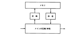
上述したような圧縮符号化/復号化装置による処理は、図15に示すように、メモリとのデータの受渡しによって進行する。従って、圧縮符号化/復号化装置に付随してメモリが設けられている。このようなメモリが果たす役割について、以下に説明する。
【0012】
まず、上述したように、動画を取り扱う圧縮符号化装置において、動き補償フレーム間予測符号化方法が用いられることに起因して必要となるフレームの順序の並べ変えのために、入力される画像信号を一時的に記憶しておくことに、かかるメモリが使用される。すなわち、かかるメモリから取出される際の順序が動き補償フレーム間予測符号化を行うために好適なものとなるように制御される。また、かかるメモリは、動き補償フレーム間予測符号化方法を行うために基準として参照されるフレーム(後述するローカルデコード画像)を記憶する役割も果たす。
【0013】
さらに、かかるメモリは、例えばシーンチェンジを含む等の各フレームの性質を認識するために、圧縮符号化/復号化装置による処理に先立って、画像信号を所定時間確保しておくためにも使用される。上述したようにメモリの使用は、動画、静止画像の何れを扱う圧縮符号化装置においても行われる。
【0014】
一方、動画を取り扱う復号化装置に付随して設けられるメモリは、まず、上述したように圧縮符号化に対応する復号化における、動き補償フレーム間予測符号化に対応する復号化において、基準として参照される信号を記憶することに使用される。また、復号化が完了した後に、フレームの順序を元の画像信号中の順序に戻す処理のために、復号化された画像信号を一時的に記憶しておくことにも使用される。すなわち、復号化された画像信号を、かかるメモリから取出す際の順序が元の画像信号の順序となるように制御される。
【0015】
このような圧縮符号化/復号化装置に付随して設けられるメモリは、画像伝送システムの性能、取り扱う画像の性質等の条件に応じて、数フレーム〜数十フレームを記憶するものとされる。このため、一般に、このようなメモリとしては、大きな記憶容量を有するものが必要とされる。例えば、従来用いられている圧縮符号化/復号化装置は、少なくとも16Mbit〜32Mbit、多い場合には、320Mbitものメモリを必要とする。
【0016】
【発明が解決しようとする課題】
上述したように、MPEGの規定に従う画像情報伝送システムにおいて用いられる圧縮符号化/復号化装置は、処理を行うために大きな記憶容量のメモリを必要とする。このため、圧縮符号化/復号化装置に付随して設けられるメモリのコストがシステム全体のコストを上昇させる要因の一つとなっていた。
【0017】
従って、この発明の目的は、MPEGの規定に従う画像情報伝送システムにおいて、圧縮符号化装置に付随して設けられるメモリの容量を削減することが可能な圧縮符号化装置および符号化方法を提供することにある。
【0018】
【課題を解決するための手段】
この発明は、画像信号を符号化する圧縮符号化装置において、
メモリと、
入力画像信号の種類を判定する入力画像判定回路と、
入力画像判定回路の判定結果に応じて、所定の入力画像信号を非可逆圧縮処理する圧縮回路と、
圧縮回路によって圧縮された信号を伸張処理する伸張回路と、
メモリに対する、圧縮回路によって圧縮された信号の書込み、および読出しを制御するメモリ制御回路と、
伸張回路によって伸張された画像信号を符号化する符号化回路を有し、
符号化回路は、MPEG規格で規定される符号化方法に従って画像信号を符号化し、
所定の画像信号は、MPEG規格で規定されるBピクチャーのみである、
ことを特徴とする圧縮符号化装置である。
【0019】
この発明は、画像信号を圧縮符号化する符号化方法において、
入力画像の種類を判定する入力画像信号判定ステップと、
入力画像信号判定ステップの判定結果に応じて、所定の入力画像信号を非可逆圧縮方法で圧縮処理する圧縮ステップと、
圧縮された信号を所定のメモリに書込むステップと、
所定のメモリに記憶された、圧縮された信号を読出すステップと、
読出された信号を伸張処理する伸張ステップと、
伸張された画像信号を伝送するために符号化する符号化ステップとを有し、
符号化ステップでは、MPEG規格で規定される符号化方法に従って画像信号を符号化し、
所定の画像信号は、MPEG規格で規定されるBピクチャーのみである、
ことを特徴とする符号化方法である。
【0022】
この発明によれば、圧縮符号化装置に付随して設けられるメモリに書込まれる信号の情報量を、MPEG規格等に従ってなされるメインの圧縮符号化とは別の圧縮/伸張を行うことによって減少させることができる。このため、必要とされるメモリ容量を削減することができる。
【0024】
【発明の実施の形態】
〔第1の実施例〕
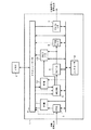
以下、この発明の第1の実施例について説明する。この発明の第1の実施例は、MPEGの規定に従う伝送システム中の圧縮符号化装置に、この発明を適用したものである。図1にこの発明の第1の実施例のブロック図を示す。圧縮符号化装置としてのエンコーダ1に付随して、メモリ2が設けられている。
【0025】
前処理部3は、画像信号を受取り、受取った画像信号に所定の処理を施す。動き検出/補償処理回路9、DCT/量子化回路4およびハフマン符号化回路5は、前処理部3の出力に大して後述するような圧縮符号化処理を行う。逆DCT/逆量子化回路10は、後述するように、動き検出/補償処理回路9による処理のために参照される信号を生成するために、DCT/量子化回路4とは逆の処理を行う。また、メモリコントローラ6は、上述したようなエンコーダ1中の各構成要素と、メモリ2との信号の受渡しを制御する。さらに、符号インターフェイス7は、符号化された信号をMPEGビデオビットストリームとして出力する。コントローラ8は、エンコーダ1全体の動作を総合的に制御する。
【0026】
信号圧縮回路11は、メモリ2の容量の削減を可能とするための圧縮を行う。かかる圧縮は、メインの圧縮、すなわちMPEG等の規定に従って行われる圧縮符号化とは別のものである。また、信号伸張回路12は、信号圧縮回路11による圧縮のなされた信号を元の信号に復元する。
【0027】
この発明の第1の実施例が行う処理のための動作について説明する。入力された画像信号は、前処理部3によって例えば(4:2:2)から(4:2:0)への変換等の所定の処理がなされた後に、信号圧縮回路11に供給される。信号圧縮回路11は、後述するようにして信号を圧縮し、メモリコントローラ6に供給する。メモリコントローラ6は、供給された信号をメモリ2に書込む。この書込みが進行する結果として、エンコードを開始するために充分な量の圧縮された画像信号がメモリ2に貯えられる。さらに、上述したようにメモリ2に貯えられた画像の例えばシーンチェンジを含んでいる等の性質を認識することが行われる。
【0028】
このようにして、エンコードを開始する条件が整った後に、コントローラ8の指示に従って、圧縮された画像信号、すなわち、メインの圧縮符号化を行う画像信号と、その画像信号の動きを検出するために参照される画像信号がメモリ2から信号伸張回路12に供給される。信号伸張回路12は、後述するようにして、供給された信号、すなわち圧縮された画像信号を元のデータに復元する。そして、復元した信号を動き検出/補償処理回路9に供給する。このようにして、復元された画像信号が動き検出/補償処理回路9に供給される際に、上述したように、入力される画像信号中の各フレームの順序の並べ変え(リオーダリング)が行われる。
【0029】
動き検出/補償処理回路9は、上述の動き補償フレーム間予測符号化方法としての動き検出/補償処理(ME/MC)を行う。すなわち、信号伸張回路12から供給された信号(メインの圧縮符号化を行う画像信号と参照画像信号)との間の動き検出を行い、その検出結果に合わせて、標準として参照されるフレームとの差分をとる動き補償処理を行うことによって、供給された信号の時間的相関を利用した情報圧縮を行う。この動き検出/補償処理回路9には、必要に応じて点線に示すように、メモリコントローラ6から画像信号に関する情報が供給される。このようにして、動き検出/補償処理回路9によって符号化された信号は、DCT/量子化回路4に供給される。また、この動き検出において参照されるフレームの画像信号が逆DCT/逆量子化回路10に保持される。なお、フレーム内符号化を必要とされる画像信号は、そのままDCT/量子化回路4に供給される。
【0030】
DCT/量子化回路4は、供給された信号に直交変換としてのDCTを施し、さらにDCTによって算出された画素値を量子化する。このようにして、供給された信号の空間的相関を利用した情報圧縮が行われる。DCT/量子化回路4によって符号化された信号は、ハフマン符号化回路5に供給されると供に、逆DCT/逆量子化回路10にも供給される。
【0031】
ハフマン符号化回路5は、供給された信号に例えば2次元ハフマン符号化を施す。ハフマン符号化は、エントロピー符号化(可変長符号化)を具体化した符号化方法である。すなわち、動き検出/補償処理回路9およびDCT/量子化回路4によって行われる、上述したような情報圧縮を伴う符号化によって生成された符号値に対して、出現確率の低い値に長い符号長を割り当て、且つ、出現確率の高い値に短い符号長を割り当てることによって、信号全体の情報量を減らすようにした符号化方法である。
【0032】
ハフマン符号化回路5が生成する信号は、メモリコントローラ6を介してメモリ2に書込まれる。そして、符号インターフェイス7を介して、所定の伝送タイミングで、MPEGビデオビットストリームとして出力される。このMPEGビデオビットストリームが最終的なエンコーダ1の出力となる。
【0033】
一方、上述したように、DCT/量子化回路4によって符号化された信号は、逆DCT/逆量子化回路10にも供給される。逆DCT/逆量子化回路10は、供給される信号に逆DCT/逆量子化を施す。逆量子化を施された信号と動き検出/補償処理回路9から供給される画像信号から、後述するように、動き検出/補償処理回路9によってなされる処理において参照されるローカルデコード画像が生成される。後述するように、逆DCT/逆量子化回路10の出力は、選択的にローカルデコード画像としてメモリ2に書込まれる。このような書込みの際には、圧縮がなされない。なお、フレーム内符号化が施された画像信号は、そのまま、メモリとして書込まれる。
【0034】
上述したメモリ2への書込みについて、図2を参照して説明する。上述したように、前処理部3は、信号圧縮回路11に画像信号を供給する。この時には、ピクチャタイプには無関係に、入力画像信号中の全てのフレームが信号圧縮回路11に供給され、圧縮された後にメモリ2に書込まれる。その後段の、すなわち伸張回路12によって伸張された信号に対する動き検出/補償処理回路9、DCT/量子化回路4および逆DCT/逆量子化回路回路10による処理を、図2中の30として総括的に示した。かかる処理により、IピクチャおよびPピクチャに基づいてローカルデコード画像が生成され、メモリ2に書込まれる。すなわち、Iピクチャについては、上述した処理30による処理結果がそのままメモリ2に書込まれる。また、Pピクチャについては、処理30による処理結果と、メモリ2から読出されたローカルデコード画像信号とが加算された後にメモリ2に書込まれる。
【0035】
上述したように、MPEG等において規定されるピクチャタイプは、Iピクチャ、PピクチャおよびBピクチャの3つであるが、このうちのPピクチャ、Bピクチャは、上述したように、他のフレームを参照して符号化される。すなわち、Pピクチャ、Bピクチャについては、動き検出/補償処理回路9によって、上述のローカルデコード画像との差分が計算され、計算された差分に基づいて動き補償フレーム間予測符号化が行われる。このため、図2に示すようにローカルデコード画像が動き検出/補償処理回路9に供給される。上述したように、ローカルデコード画像は、メモリ2に書込まれる時に圧縮されないので、メモリ2から動き検出/補償処理回路9に供給される時に伸張されない。
【0036】
他方、一般に、ある信号に対して圧縮/伸張がなされた場合、完全に元に戻ることは無く、ある程度の誤差を含むものとなる。個々のフレームの伝送に関する限りにおいては、このような誤差は、伝送システムに要求される画像品質に対して許容される範囲内であれば、何ら問題とはならない。しかしながら、上述したように、ローカルデコード画像は、他のフレームの符号化に関与するので、ローカルデコード画像に対して圧縮/伸張がなされると、圧縮/伸張によって生じる誤差は、画像信号の広範な部分の符号化に対して影響を与え、伝送される画像全体の品質を低下させる要因となるおそれがある。このため、上述したように、ローカルデコード画像として用いられるIピクチャおよびPピクチャがメモリ2に書込まれる時、およびメモリ2から動き検出/補償処理回路9に供給される際には、圧縮/伸張がなされない。
【0037】
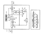
メインの圧縮とは別の圧縮、すなわち信号圧縮回路11によってなされる圧縮について詳述する。かかる圧縮は、例えば差分パルス符号変調方法(以下、DPCMと表記する)によって行われる。この発明の第1の実施例においては、5画素分に相当する40ビット(すなわち、8(ビット/画素)×5画素=40ビット)を32ビットに圧縮する。図3に信号圧縮回路11の詳細な構成を示す。切替え制御回路110は、スイッチ44、スイッチ45およびマルチプレクサ48を制御することにより、各画素を単位として、供給先を切替える。
【0038】
画像信号は、画素毎に、すなわち8ビット単位で供給される。第1番目の画素が供給された時には、切替え制御回路110の指令によって、スイッチ44が端子49と端子51を接続する。従って、供給された8ビットの画素データは、マルチプレクサ48およびスイッチ45に供給される。さらに、第1番目の画素データが供給された時には、切替え制御回路110の指令によって、スイッチ45が端子52と端子54を接続するようになされる。このため、第1番目の画素データは、フリップフロップ42に供給される。
【0039】
第2番目の画素が供給されると、第2番目の画素データと、上述したようにフリップフロップ42に記憶された第1番目の画素データとの差分が減算器46によって計算される。この差分が量子化器41に供給され、6ビットに量子化される。ところで、第2番目の画素が供給された時には、切替え制御回路110の指令によって、スイッチ44が端子50と端子51を接続するようになされる。このため、上述したようにして生成された6ビットのデータは、マルチプレクサ13に供給されると供に、逆量子化器43に供給される。
【0040】
逆量子化器43は、供給された6ビットのデータを逆量子化し、加算器47に供給する。加算器47は、逆量子化器43から供給されたデータと、フリップフロップ42に記憶されていた第1番目の画素データとを加算して、第2番目の画素データを復元する。ところで、第2番目の画素が供給された時には、切替え制御回路110の指令によって、スイッチ45が端子53と端子54を接続するようになされる。従って、上述の加算の結果、すなわち復元された第2番目の画素データがフリップフロップ42に記憶される。このようにして、フリップフロップ42に記憶された復元された画素データは、次に入力される画素データを処理する際に減算器46、加算器47において用いられる。
【0041】
さらに、3番目〜5番目までの画素データも2番目の画素データと同様に処理され、各々6ビットのデータとされる。この結果、図3の下方に示すように、5画素分のデータ(40ビット)が32ビットのデータに圧縮される。このようにして32ビットのデータが生成される毎に、32ビットを転送できるバスを介して、メモリ2に出力される。このようにして、5画素に対応する圧縮されたデータがメモリ2上の1アドレスに書込まれる。
【0042】
その後、6番目以降の画素データについても、上述の動作と同様にして、5画素分の40ビットのデータを処理単位として、32ビットのデータに圧縮することが行われる。従って、信号圧縮回路11に入力される画像信号について、常に4/5の圧縮がなされる。
【0043】
次に、メインの圧縮とは別の圧縮、すなわち信号圧縮回路11による圧縮が施されたデータから、元のデータを復元するための伸張について説明する。かかる伸張は、信号伸張回路12によってなされる。その基本構成は、信号圧縮回路11によってなされる圧縮の逆処理を行うものである。従って、この発明の第1の実施例においては、上述したようにして生成された32ビットのデータを元の40ビットのデータに戻す処理がなされる。図4に信号伸張回路12の詳細な構成を示す。切替え制御回路120は、デマルチプレクサ61およびスイッチ64によって、画素を単位としてなされる供給先の切替えを制御する。
【0044】
上述したように、コントローラ8の指令によってメモリ2から取出された32ビットのデータがデマルチプレクサ61に供給される。デマルチプレクサ61は、供給される32ビットのデータのうちの8ビットの画素データ(上述の圧縮において、ビット長が8ビットのままとされる画素データ、すなわち処理単位とされる5画素のうちの最初の画素データ)が第1番目に処理され、その後2番目以降に6ビットのデータが順に処理されるように、後段に画素データを供給する。
【0045】
デマルチプレクサ61から第1番目のデータとして8ビットのデータが出力される時には、切替え制御回路120の指令によって、スイッチ64が端子66と端子68を接続する。従って、8ビットのデータは、信号伸張回路12を通過すると供に、フリップフロップ65に記憶される。
【0046】
また、デマルチプレクサ61から第2番目のデータとして6ビットのデータが出力される時には、逆量子化器62によって6ビットのデータが逆量子化され、加算器63に供給される。加算器63は、逆量子化器62から供給されるデータと、フリップフロップ65に記憶された第1番目のデータとを加算し、第2番目のデータを復元する。ところで、デマルチプレクサ61から第2番目のデータとして6ビットのデータが出力される時には、切替え制御回路120の指令によって、スイッチ64が端子67と端子68を接続する。このため、加算器63の出力すなわち復元された2番目の画素データは、信号伸張回路12を通過すると供に、フリップフロップ65に記憶される。このようにして、フリップフロップ65に記憶された復元された画素データは、次に入力される画素データを処理する際に加算器63において用いられる。
【0047】
その後、第3番目〜第5番目のデータについても同様な処理が行われる。この結果、図4の下方に示すように、32ビットのデータが40ビットのデータに伸張され、8ビット/画素の5画素分のデータに戻される。その後、信号伸張回路12に供給されるデータについても、上述の動作と同様にして、32ビットのデータを1まとまりとして、40ビットすなわち5画素分のデータに戻すことが行われる。従って、信号伸張回路12に入力される圧縮データについて、常に5/4の伸張がなされる。
【0048】
また、この発明の第1の実施例では、メインの圧縮符号化とは別の圧縮/伸張として、8画素分の40ビットを32ビットに圧縮する4/5のDPCM圧縮を行う場合について説明したが、この他にも、削減したいメモリ容量および伝送される画像に要求される品質等の観点から、最適な圧縮率を用いることが可能である。また、1画素当たりのビット数が8ビット以外のデータ長からなる画像信号を扱う場合にも、この発明を適用することができる。
【0049】
以上のような圧縮/伸張を輝度信号とクロマ信号の両方に行うことも可能であるし、クロマ信号にのみ行うことも可能である。何れの方法を適用するかは、削減したいメモリ量と、伝送される画像に要求される品質等に応じて決定すれば良い。また、削減したいメモリ量と、伝送される画像に要求される品質等を考慮して有効なものであれば、DPCM圧縮以外の圧縮方法を用いても良い。
【0050】
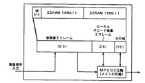
この発明の第1の実施例において、使用されるメモリの量について図5に示す。またこの発明を適用しない場合について、図6に示す。ここでは、圧縮符号化に先立って、5フレーム分の原画像を記憶するようになされた圧縮符号化装置について、この発明を適用することによる効果を説明する。
【0051】
図6に示すこの発明を適用しない場合においては、原画像とそれ以外の部分(ローカルデコード画像およびその他)の比率が65:41である。これに対して、図5に示す、第1の実施例においてクロマ信号にのみ4/5の圧縮を行う場合には、原画像の情報量が圧縮されるので、原画像とそれ以外の部分の比率が59:41である。このような原画像の情報量の圧縮は、上述したようなメインの圧縮とは別の圧縮符号化によって可能となるものである。また、図5、図6の上部に、各々の場合に使用されるメモリ容量を示した。これらの図によれば、実際に削減されるメモリ容量は、4Mbitとなる。
【0052】
図6の場合には、2個の16Mbitメモリに加えて、4Mbitメモリ1個が必要とされる。すなわち、この場合には3個のメモリが必要となる。これに対して、図5においては、必要なメモリ容量が削減されたために、2個の16Mbitメモリを用いれば圧縮符号化を行うことが可能である。このため、図5においては、圧縮符号化装置が1チップとして設計される場合に、メモリとデータの受渡しをするためのLSIのピンおよびバスの数も減少することになる。すなわち、この発明を適用することによって、圧縮符号化装置の全体構成が単純化されるという効果も得られる。
【0053】
〔第2の実施例〕
上述したようなこの発明の第1の実施例は、図2を参照して説明したように、入力された画像信号に対して、メインの圧縮とは別の圧縮、すなわち信号圧縮回路11による圧縮を行ってメモリに書込む時には、ピクチャータイプに関係なく、画像信号中の全ての部分についてかかる圧縮を行うものである。これに対して、この発明の第2の実施例として、かかる圧縮をピクチャータイプに応じて選択的に行うようにするものも可能である。
【0054】
この発明の第2の実施例の全体構成は、図1を用いて上述したこの発明の第1の実施例と同様である。但し、図1中に点線で示した経路を介して、ピクチャタイプについての情報が前処理部分3からメモリコントローラ6、さらには動き検出/補償処理回路9に供給される。信号圧縮回路11および信号伸張回路12における画像信号の取り扱いについて、図7を用いて説明する。この発明の第1の実施例の説明において用いた図2と同様に、図7は、前処理部3、およびその後段における動き検出/補償処理回路9、DCT/量子化回路4および逆DCT/逆量子化回路10による処理を総括的に示す30による処理を示している。図7に示すように、この発明の第2の実施例においては、メインの圧縮とは別の圧縮/伸張は、Bピクチャのみに施され、IピクチャおよびPピクチャには、施されない。
【0055】
すなわち、図7においてBピクチャのみが前処理部3から信号圧縮回路11に供給され、圧縮された後にメモリ2に書込まれる。IピクチャおよびPピクチャは、圧縮されずにメモリ2に書込まれる。その後段の上述したように30として総括的に示した処理においては、IピクチャおよびPピクチャがメモリ2から読出されて伸張されずに、直接、30として総括的に示した処理の対象とされる。但し、Pピクチャについては、ローカルデコード画像が差引かれた後に、処理対象とされる。また、Bピクチャは、メモリ2から読出されて伸張された後に、信号伸張回路12に供給される。信号伸張回路12によって伸張されたBピクチャからローカルデコード画像が差引かれた後に、上述した処理30の処理対象とされる。
【0056】
処理30によるIピクチャに基づく処理結果がそのままメモリ2に書込まれる。また、処理30によるPピクチャに基づく処理結果にメモリ2から読出されたローカルデコード画像が加算された後にメモリ2に書込まれる。このようにしてメモリ2に書込まれたPピクチャおよびBピクチャに基づく処理30による処理結果がローカルデコード画像として使用される。
【0057】
上述したように、Bピクチャは、圧縮符号化/復号化において他のピクチャを取り扱うために参照されることがない。このため、一般に、メインの圧縮において、Bピクチャの圧縮率は、IピクチャおよびPピクチャよりも高い値に設定される。従って、メインの圧縮によって、Bピクチャに対して生じる画質劣化は、IピクチャおよびPピクチャに対して生じる画質劣化より大きくなる。このような状況を考慮すると、メインの圧縮とは別の圧縮/伸張によってBピクチャに生じる画質劣化についての許容範囲は、IピクチャおよびPピクチャより広いものとなる。そこで、IピクチャおよびPピクチャにメインの圧縮とは別の圧縮/伸張を行わない分、Bピクチャに対する、メインの圧縮とは別の圧縮/伸張の圧縮率を大きくすることが可能である。
【0058】
上述したこの発明の第2の実施例においては、ローカルデコード画像の重要性を考慮して、Iピクチャ、Pピクチャに対しては、圧縮/伸張がなされない。ところで、伝送画像に要求される品質等の条件によっては、ローカルデコード画像として参照されることを考慮しても、ある程度の誤差が許容される場合もある。このような場合には、Iピクチャ、Pピクチャに対して、誤差がその許容範囲内となるような圧縮率で、メインの圧縮とは別の圧縮を行うようにすることも可能である。
【0059】
〔第3の実施例〕
さらに、メインの圧縮におけるアクセスの効率に関して改善を図ったものとして、この発明の第3の実施例がある。この発明の第3の実施例についての説明に先立って、メインの圧縮におけるアクセスの効率と、メインの圧縮とは別の圧縮がなされる単位の大きさの関係について説明する。上述したように、メインの圧縮とは別の圧縮には、DPCM圧縮が用いられる。
【0060】
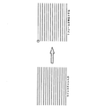
一般のDPCM圧縮では、1フレームまたは1ラインの単位で圧縮が行われる。この様子を図8に示す。図8において、各水平線が1ラインを示している。さらに、図8では、簡略化のため、15本の水平線を用いて1フレームを示す。丸印を付した位置がリセット位置である。すなわち、このリセット位置の画素データのみが圧縮されずに伝送され、それ以降の画素データについては、全て前データとの差分が伝送される。従って、1フレーム分の圧縮データから、例えば最後の画素データのみを取出したい場合にも、丸印を付して示したリセット位置の画素データを開始点として順に伸張を行わなければならない。
【0061】
これに対して、上述したこの発明の第1の実施例中の信号圧縮回路11においては図9に示すように、1ラインよりも小さい単位(5画素)毎にリセット位置が設定されることになるため、信号伸張回路12によって伸張がなされる際に、任意の位置のデータに対するアクセスが容易なものとされている。
【0062】
上述した観点から、この発明の第3の実施例について説明する。全体構成は、図1を用いて上述したこの発明の第1の実施例と同様である。そして、図1中の信号圧縮回路11において、以下に説明するような方法で、メインの圧縮とは別の圧縮としてのDPCM圧縮が行われることにより、DCT/量子化回路4および逆DCT/逆量子化回路10によって処理がなされる際に、任意の位置のブロックに対するアクセスが容易となる。
【0063】
上述したようなDPCM圧縮について、図10を参照して説明する。メインの圧縮においてアクセスがなされる単位(MPEG等においては、マクロブロック)を1ブロックと称することにすると、1ブロック以下の所定の単位で、上述したようなDPCM圧縮のリセットが行われる。以下の説明においては、このようなDPCM圧縮の単位をDPCMブロックと称する。図10中の右側に示した図において、丸印を付した位置がリセット位置である。リセット位置の画素は、そのままのデータ長で伝送される。また、図10中の右側に示した図において1個のDPCMブロックは、リセット位置を開始点とし、短く区切られたラインの断片の3本分からなる。
【0064】
従って、図10の例においては、1ブロック分のデータにアクセスするためには、ブロックの位置によって異なる幾つかのDPCMブロックにアクセスすれば良いことになる。例えば、図中のブロックAにアクセスするためには、4個のDPCMブロックにアクセスすれば良い。1ブロック分のデータにアクセスするために必要なDPCMブロック数が最大となるのは、例えばブロックBにアクセスする場合であり、この時には、図に示されるように、6個のDPCMブロックにアクセスすれば良い。
【0065】
このようにして、DPCMブロックの大きさをメインの圧縮の単位(上述のブロック)のサイズ以下として、メインの圧縮とは別の圧縮としてのDPCM圧縮が行われることによって、メインの圧縮におけるアクセス効率を低下させずに、メインの圧縮とは別の圧縮を行うことが可能となる。従って、この発明が適用される画像情報伝送システム本来のアクセス効率を保ちながら、圧縮符号化装置に付随して設けられるメモリの容量を削減することが可能となる。
【0066】
〔第4の実施例〕
上述したこの発明の第1の実施例等においては、メインの圧縮においてフィードバック処理が行われていた。すなわち、メインの圧縮は、動き検出/補償処理回路9、DCT/量子化回路4およびその後段のハフマン符号化回路5によって行われるが、DCT/量子化回路4の出力は、逆DCT/逆量子化回路10にも供給され、逆DCT/逆量子化される。かかる逆DCT/逆量子化によって生成されたIピクチャ、Pピクチャは、圧縮されずにメモリ2に書込まれ、動き検出/補償処理回路9によって、画像信号中の他のフレームに属するPピクチャおよびBピクチャが処理される際に、ローカルデコード画像として参照される。
【0067】
従って、一連なりの画像信号に、メインの圧縮のうちの1ステップである動き検出/補償処理を施す際に、かかる画像信号中のフレームについてなされる処理の結果(逆DCT/逆量子化回路10の出力)が他のフレームの処理に関与することになる。このため、上述のこの発明の第1の実施例等においては、図11に示すように、メインの圧縮とは別の圧縮/伸張は、信号中の各フレームについて選択的に行われる。すなわち、上述したように、ローカルデコード画像等のメインの処理において参照される信号部分は、メインの圧縮とは別の圧縮/伸張の対象とされない。
【0068】
これに対し、この発明の第4の実施例として、メインの圧縮においてフィードバック処理が行われない圧縮符号化装置に対して、この発明を適用することも可能である。このような圧縮符号化装置は、JPEG等の静止画像を伝送するための規定に従う、画像伝送システムにおいて用いられるものである。かかるシステムは、動画を扱うMPEG等の規定に従うものと異なり、動き補償フレーム間予測符号化を施す必要がない。このため、上述したようなローカルデコード画像が用いられる必要がないので、特定のピクチャタイプに対して、メインの圧縮とは別の圧縮/伸張を行わない等の制御を行う必要も無い。そこで、図12に示すように、信号圧縮回路11および信号伸張回路12は、供給される全ての画像信号を圧縮/伸張するようになされる。
【0069】
この発明の第4の実施例の全体構成を図13に示す。図13において、図1を用いて説明したこの発明の第1の実施例におけるものと同様の構成要素には、同一の番号を付した。上述したように、動き補償フレーム間予測符号化を施す必要が無いので、図13中には、図1中の動き検出/補償処理回路9が含まれていない。さらに、上述のローカルデコード画像が用いられる必要も無いので、ローカルデコード画像を生成するために設けられている図1中の逆DCT/逆量子化回路4は、図13中には、含まれていない。また、上述したような理由で、信号圧縮回路11および信号伸張回路12は、供給される全ての信号を圧縮/伸張する。
【0070】
この場合には、供給される全ての信号が一定の圧縮率で圧縮/伸張され、それに見合うメモリ容量の削減が可能となる。
【0071】
〔第5の実施例〕
上述したこの発明の第1の実施例〜第4の実施例は、何れも圧縮符号化装置にこの発明を適用したものである。これに対して、以下に説明するこの発明の第5の実施例は、例えば、上述のこの発明の第1の実施例を含む、MPEGの規定に従う伝送システム中の復号化装置にこの発明を適用したものである。このようにすれば、復号化装置に付随して設けられているメモリの容量を削減することができる。図14に、この発明の第5の実施例の全体構成を示す。復号化装置としてのデコーダ81に付随して、メモリ82が設けられている。
【0072】
符号インターフェイス87は、圧縮符号化信号を受取り、受取った圧縮符号化信号画像信号に所定の処理を施し、後段に供給する。ハフマン復号化回路85、逆DCT/逆量子化回路84および動き補償処理回路89は、MPEGの規定に従って、後述するような復号化処理を行う。動き補償処理回路89は、処理結果の内、IピクチャおよびBピクチャに基づく所定のものをローカルデコード画像としてメモリコントーラ86に供給する。このようにして、ローカルデコード画像がメモリ82に書込まれ、動き補償処理回路89の動作において必要に応じて読出されて参照される。メモリコントローラ86は、上述したようなデコーダ81中の各構成要素と、メモリ82との信号の受渡しを制御する。後処理部83は、復号された画像信号を受取り、所定の処理を施した後に、デコーダ81の出力として後段に出力する。コントローラ88は、デコーダ81全体の動作を総合的に制御する。
【0073】
信号圧縮回路91は、メモリ82の容量の削減を可能とするための圧縮を行う。信号伸張回路90は、信号圧縮回路91によって圧縮のなされた信号から、元の信号を復元する。
【0074】
次にこの発明の第5の実施例の動作について説明する。デコーダ81に対する入力となる、伝送されてきた圧縮符号化信号は、符号インターフェイス87を介して、メモリ82に書込まれる。そして、コントローラ88の指令に従って取出され、ハフマン復号化回路85に供給される。ハフマン復号化回路85は、供給される圧縮符号化信号に、ハフマン符号化に対応する復号化(可変長復号化)を施す。
【0075】
ハフマン復号化の結果として得られた信号は、逆DCT/逆量子化回路84に供給される。逆DCT/逆量子化回路84は、供給された信号に上述したDCT/量子化による符号化に対応する、逆DCT/逆量子化による復号化を施す。そして、逆DCT/逆量子化による復号化のなされた信号を、動き補償処理回路89に供給する。また、この信号のうち、Iピクチャ、Pピクチャは、動き補償処理回路89による処理において参照されるために、メモリ82に書込まれる。但し、Iピクチャは、逆DCT/逆量子化回路84によって復号化された後、そのままメモリ82に書込まれる。Pピクチャは、動き補償処理回路89にて動き補償されたものがメモリ82に書込まれる。
【0076】
動き補償処理回路89は、上述したようにしてメモリ82に書込まれていたIピクチャ、Pピクチャを参照して、供給された信号に基づいて動き補償処理を行う。かかる動き補償処理は、上述した圧縮符号化における動き検出/補償処理に対応する復号化である。動き補償処理回路89の出力は、画像信号として完全に復号された各フレームからなる。ただし、上述したように、圧縮符号化の際に、動き補償フレーム間予測符号化を行うために並べ変えが行われるので、これらのフレームの順序は、元の画像信号中の順序とは異なる。従って、復号化された画像信号中のフレームの順序を元に戻すために、一旦メモリ82に書込まれた後に、元の画像信号中の順序で取出される。
【0077】
上述したフレームの順序を元に戻すための処理について、具体的に説明する。動き補償処理回路89の出力は、信号圧縮回路91に供給される。信号圧縮回路91は、供給された信号に圧縮を施す。そして、圧縮された信号をメモリコントローラ86を介してメモリ82に書込む。メモリ82に書込まれた信号は、コントローラ88の指令に従って、元の画像信号中のフレームの順序に沿って取出される。このような取出しの際には、例えばオーディオ信号等の画像信号以外の信号との同期も考慮される。取出された信号が信号伸張回路90によって伸張され、元の画像信号が復元される。復元された画像信号は、後処理部83を介して、後段に出力される。
【0078】
このような、圧縮符号化に対応する復号化が完了した後に、復号化された画像信号中のフレームの順序を元の画像信号中のフレームの順序に戻すために必要とされる、メモリ82への書込み/メモリ82からの取出しに際して、信号圧縮回路91/信号伸張回路90によって圧縮/伸張がなされることによって、メモリ82の容量を削減することができる。
【0079】
上述したこの発明の第5の実施例は、例えば第1の実施例によってなされる圧縮符号化に対応する復号化を行う復号化装置に、この発明を適用したものである。同様に、この発明の第2の実施例および第3の実施例によってなされる圧縮符号化に対応する復号化を行う復号化装置として、この発明の第5の実施例を適用することも可能である。さらに、例えばこの発明の第4の実施例等の、JPEG等の規定に従って静止画像に対して圧縮符号化を施す圧縮符号化装置に対応して、復号化を行う復号化装置に、この発明の第5の実施例の復号化装置を適用することも可能である。この場合には、動き補償処理を行うことに対応するための構成が不要となる。
【0080】
また、この発明は、上述したような実施の形態に限定されることなく、この発明の要旨を逸脱しない範囲で種々の応用および変形が考えられる。
【0081】
【発明の効果】
上述したように、この発明は、MPEGの規定に従って、動画または静止画像等の画像信号等を伝送するシステムに用いられる、圧縮符号化装置において、各々の規定に従ってなされるメインの圧縮符号化とは別の圧縮を行うようにしたものである。このため、圧縮符号化装置による処理のために必要となるメモリの容量を削減することが可能となり、システム全体のコストを低減させることができる。また、メインの圧縮符号化とは別の圧縮における圧縮率等を調整することによって、伝送される画像の品質等に適合するように、メモリの容量の削減を行うことができる。
【0082】
また、この発明の第2の実施例において説明したように、信号中の特定の部分に対してのみ、メインの圧縮符号化とは別の圧縮を行うように制御するようにした場合には、かかる特定の部分に対して圧縮率等を高く設定することができる。この場合に、メインの圧縮符号化とは別の圧縮を行わない部分は、フィードバック処理を受ける信号中の部分、すなわち信号中の他の部分に施されるメインの圧縮符号化において、基準として参照される部分である。このような制御によって、基準として用いられる部分は、メインの圧縮符号化とは別の圧縮によって生じる誤差を含まないものとされる。このため、上述の信号中の特定の部分に対する圧縮率等を高く設定しても伝送される画像の品質が劣化しないようにすることができる。
【0083】
さらに、この発明の第3の実施例において説明したように、メインの圧縮符号化とは別の圧縮を、メインの圧縮符号化におけるアクセスの単位以下の所定の単位毎に行うようにする場合には、メインの圧縮符号化におけるアクセスの効率を劣化させずに、メインの圧縮符号化とは別の圧縮を行うことができる。従って、MPEGの規定に従って画像信号等を伝送するシステム本来のアクセス効率を保ちながら、圧縮符号化装置に付随して設けられるメモリの容量を削減することができる。
【図面の簡単な説明】
【図1】この発明の第1の実施例の構成を示すブロック図である。
【図2】この発明の第1の実施例における、ピクチャタイプに応じてなされる制御について説明するための略線図である。
【図3】この発明の第1の実施例の一部の構成を詳細に示すブロック図である。
【図4】この発明の第1の実施例の他の一部の構成を詳細に示すブロック図である。
【図5】この発明の第1の実施例によって達成される、メモリ容量の削減について説明するための略線図である。
【図6】図5との比較のために、この発明が適用されない場合について説明するための略線図である。
【図7】この発明の第2の実施例における、ピクチャタイプに応じてなされる制御について説明するための略線図である。
【図8】一般的なDPCM圧縮について説明するための略線図である。
【図9】この発明の第1の実施例においてなされるDPCM圧縮について説明するための略線図である。
【図10】この発明の第3の実施例においてなされるDPCM圧縮について説明するための略線図である。
【図11】動画を伝送するシステムに用いられる圧縮符号化/復号化装置に対して、この発明が適用される場合に行われる制御について説明するための略線図である。
【図12】静止画像を伝送するシステムに用いられる圧縮符号化/復号化装置に対して、この発明が適用される場合に行われる制御について説明するための略線図である。
【図13】この発明の第4の実施例の構成を示すブロック図である。
【図14】この発明の第5の実施例の構成を示すブロック図である。
【図15】MPEG、JPEG等の画像伝送システムにおける、従来の圧縮符号化/復号化について説明するための略線図である。
【符号の説明】
1・・・エンコーダ、2・・・メモリ、3・・・前処理部、4・・・離散コサイン変換(DCT)/量子化回路、5・・・ハフマン符号化回路、6・・・メモリコントローラ、7・・・符号インターフェイス、8・・・コントローラ、9・・・動き検出/補償処理回路、10・・・逆離散コサイン変換(逆DCT)/逆量子化回路、11・・・信号圧縮回路、12・・・信号伸張回路、41・・・量子化器、42・・・フリップフロップ、43・・・逆量子化器、44・・・スイッチ、45・・・スイッチ、46・・・減算器、47・・・加算器、48・・・マルチプレクサ、110・・・切替え制御回路、61・・・デマルチプレクサ、62・・・逆量子化器、63・・・加算器、64・・・スイッチ、65・・・フリップフロップ、120・・・切替え制御回路、81・・・デコーダ、82・・・メモリ、83・・・後処理部、84・・・逆離散コサイン変換(逆DCT)/逆量子化回路、85・・・ハフマン復号化回路、86・・・メモリコントローラ、87・・・符号インターフェイス、88・・・コントローラ、89・・・動き補償処理回路、90・・・信号伸張回路、91・・・信号圧縮回路[0001]
BACKGROUND OF THE INVENTION
This invention is, for example, MPE G Compression encoding apparatus and encoding method for compressing image signal with high efficiency in a system for transmitting image information complying with regulations To the law Related.
[0002]
[Prior art]
In a system for transmitting image information, a compression encoding device that compresses and encodes an image signal and a decoding device that decodes the image signal from the compression encoded signal are indispensable elements. In order for the compression encoding apparatus and decoding apparatus to be compatible with multimedia, that is, to be applicable to various image information transmission means or reception means, MPEG, JPEG, etc. are defined as regulations to be followed. .
[0003]
MPEG is a rule relating to a method for transmitting moving images such as video images. As a compression encoding method, a motion compensation interframe predictive encoding method that performs information compression using temporal correlation, and a discrete cosine transform (hereinafter referred to as DCT) as orthogonal encoding that performs information compression using spatial correlation. ) And the Huffman coding method as entropy coding (variable length coding) that performs information compression using the bias in the appearance probability of codes generated by the above coding method. is there.
[0004]
Of these, the motion compensation interframe predictive encoding method is required in a system for transmitting moving images and is employed in MPEG and the like. Motion compensation interframe predictive coding is performed with reference to other frames in units of frames in the signal. In MPEG, regarding motion compensation interframe predictive coding, three picture types of I picture, P picture, and B picture are defined for each frame.
[0005]
An I picture is an image that is encoded without intra-frame encoding, that is, without referring to another frame, and is not a target of motion compensation inter-frame predictive encoding. A P picture is an image that is subjected to forward prediction, that is, motion compensation interframe predictive coding by referring to a preceding frame. Furthermore, the B picture is an image for which bi-directional prediction is performed. That is, it is an image that is subjected to motion compensation interframe predictive coding by referring to the preceding frame and the subsequent frame.
[0006]
In addition, the picture types of frames that are referred to in order to perform motion compensation interframe predictive coding for other frames are I pictures and P pictures. B pictures cannot be referenced. That is, a frame referred to for motion compensation interframe predictive coding of a P picture is a preceding I picture or P picture. In addition, in order to perform motion compensation interframe predictive encoding of a B picture, it is necessary to refer to a preceding frame (I picture or P picture) and a succeeding frame (I picture or P picture).
[0007]
Therefore, the process of performing motion compensation interframe predictive encoding of a B picture can be performed only after a frame (I picture or P picture) at a subsequent position in the input image signal is processed. For this reason, the order of the frames in the input image signal is different from the order of processing. Therefore, after the rearrangement (reordering) of the frames in the input image signal is performed, the frames are supplied to means for performing motion compensation interframe predictive coding. As will be described later, a memory is used when performing such rearrangement.
[0008]
After performing such motion-compensated interframe predictive coding, the compression coding apparatus in accordance with the MPEG standard performs coding by DCT as described above and Huffman coding as entropy coding (variable length coding). By doing so, a signal that has been compression-encoded is generated. Then, such a compressed encoded signal is transmitted.
[0009]
Therefore, the image signal generated by decoding the compression-coded signal transmitted from the decoding apparatus is the one in which the frame order is rearranged. For this reason, processing for returning the frame order to the original is necessary. As will be described later, when performing such processing for returning the frame order, a memory provided in association with the decoding device is used.
[0011]
The processing by the compression encoding / decoding device as described above proceeds by data transfer with the memory as shown in FIG. Therefore, a memory is provided in association with the compression encoding / decoding device. The role played by such a memory will be described below.
[0012]
First, as described above, an input image signal for rearranging the order of frames required due to the use of the motion compensation interframe predictive encoding method in a compression encoding apparatus that handles moving images. Such a memory is used to temporarily store. That is, control is performed so that the order of extraction from such a memory is suitable for performing motion compensation interframe predictive coding. Such a memory also serves to store a frame (a local decoded image described later) referred to as a reference in order to perform the motion compensation interframe predictive coding method.
[0013]
In addition, such a memory is also used to reserve an image signal for a predetermined time prior to processing by the compression encoding / decoding device in order to recognize the properties of each frame including, for example, scene changes. The As described above, the memory is used in a compression coding apparatus that handles both moving images and still images.
[0014]
On the other hand, a memory provided in association with a decoding apparatus that handles moving images is first referred to as a reference in decoding corresponding to motion compensation interframe prediction encoding in decoding corresponding to compression encoding as described above. Used to store the generated signal. It is also used to temporarily store the decoded image signal for the process of returning the frame order to the order in the original image signal after the decoding is completed. That is, control is performed so that the order in which the decoded image signals are taken out from the memory is the order of the original image signals.
[0015]
The memory provided in association with such a compression encoding / decoding device stores several frames to several tens of frames according to conditions such as the performance of the image transmission system and the properties of the images to be handled. For this reason, in general, such a memory is required to have a large storage capacity. For example, a conventionally used compression encoding / decoding device requires a memory of at least 16 Mbits to 32 Mbits and, in many cases, 320 Mbits of memory.
[0016]
[Problems to be solved by the invention]
As mentioned above, MPE G A compression encoding / decoding device used in an image information transmission system that complies with regulations requires a memory with a large storage capacity in order to perform processing. For this reason, the cost of the memory provided in association with the compression encoding / decoding device has been one of the factors that increase the cost of the entire system.
[0017]
Therefore, the object of the present invention is to provide MPE. G In an image information transmission system that complies with regulations, In place Compression encoding apparatus capable of reducing the capacity of the accompanying memory And encoding method Is to provide.
[0018]
[Means for Solving the Problems]
The present invention relates to a compression encoding apparatus for encoding an image signal.
Memory,
An input image determination circuit for determining the type of the input image signal;
Depending on the determination result of the input image determination circuit, a predetermined input image signal is Irreversible A compression circuit for compression processing;
A decompression circuit for decompressing the signal compressed by the compression circuit;
A memory control circuit for controlling writing and reading of the signal compressed by the compression circuit to the memory;
An encoding circuit for encoding the image signal expanded by the expansion circuit;
The encoding circuit encodes an image signal in accordance with an encoding method defined in the MPEG standard,
The predetermined image signal is only a B picture defined by the MPEG standard.
This is a compression coding apparatus characterized by the above.
[0019]
The present invention relates to an encoding method for compressing and encoding an image signal.
An input image signal determination step for determining the type of the input image;
Depending on the determination result of the input image signal determination step, a predetermined input image signal is Irreversible A compression step for compressing with a compression method;
Writing the compressed signal into a predetermined memory;
Reading a compressed signal stored in a predetermined memory;
A decompression step for decompressing the read signal;
An encoding step for encoding to transmit the decompressed image signal;
In the encoding step, the image signal is encoded according to an encoding method defined in the MPEG standard,
The predetermined image signal is only a B picture defined by the MPEG standard.
This is an encoding method characterized by this.
[0022]
This According to the invention, the amount of information of a signal written in a memory provided in association with the compression coding apparatus is reduced by performing compression / expansion different from the main compression coding performed according to the MPEG standard or the like. Can be made. For this reason, the required memory capacity can be reduced.
[0024]
DETAILED DESCRIPTION OF THE INVENTION
[First embodiment]
The first embodiment of the present invention will be described below. In the first embodiment of the present invention, the present invention is applied to a compression coding apparatus in a transmission system in accordance with the MPEG standard. FIG. 1 shows a block diagram of a first embodiment of the present invention. A
[0025]
The
[0026]
The
[0027]
An operation for processing performed by the first embodiment of the present invention will be described. The input image signal is supplied to the
[0028]
In this way, after the condition for starting encoding is established, in order to detect the compressed image signal, that is, the image signal to be subjected to main compression encoding, and the movement of the image signal in accordance with the instruction of the
[0029]
The motion detection / compensation processing circuit 9 performs motion detection / compensation processing (ME / MC) as the above-described motion compensation interframe predictive coding method. That is, motion detection is performed between the signals supplied from the signal expansion circuit 12 (image signal for main compression encoding and reference image signal), and the frame referred to as a standard is matched with the detection result. By performing motion compensation processing that takes a difference, information compression is performed using temporal correlation of the supplied signals. The motion detection / compensation processing circuit 9 is supplied with information related to the image signal from the memory controller 6 as indicated by a dotted line as necessary. In this way, the signal encoded by the motion detection / compensation processing circuit 9 is supplied to the DCT / quantization circuit 4. In addition, the image signal of the frame referred to in this motion detection is held in the inverse DCT / inverse quantization circuit 10. Note that an image signal that requires intraframe coding is supplied to the DCT / quantization circuit 4 as it is.
[0030]
The DCT / quantization circuit 4 performs DCT as orthogonal transform on the supplied signal, and further quantizes the pixel value calculated by the DCT. In this way, information compression using the spatial correlation of the supplied signal is performed. The signal encoded by the DCT / quantization circuit 4 is supplied to the Huffman encoding circuit 5 and also to the inverse DCT / inverse quantization circuit 10.
[0031]
The Huffman encoding circuit 5 performs, for example, two-dimensional Huffman encoding on the supplied signal. Huffman coding is a coding method that embodies entropy coding (variable length coding). That is, a long code length is set to a value having a low appearance probability with respect to a code value generated by the encoding with information compression as described above performed by the motion detection / compensation processing circuit 9 and the DCT / quantization circuit 4. In this encoding method, the amount of information of the entire signal is reduced by assigning a short code length to a value having a high appearance probability.
[0032]
A signal generated by the Huffman encoding circuit 5 is written into the
[0033]
On the other hand, as described above, the signal encoded by the DCT / quantization circuit 4 is also supplied to the inverse DCT / inverse quantization circuit 10. The inverse DCT / inverse quantization circuit 10 performs inverse DCT / inverse quantization on the supplied signal. As will be described later, a local decoded image to be referred to in processing performed by the motion detection / compensation processing circuit 9 is generated from the signal subjected to inverse quantization and the image signal supplied from the motion detection / compensation processing circuit 9. The As will be described later, the output of the inverse DCT / inverse quantization circuit 10 is selectively written into the
[0034]
The above-described writing to the
[0035]
As described above, there are three picture types defined in MPEG and the like: I picture, P picture, and B picture. Of these, P picture and B picture refer to other frames as described above. Is encoded. That is, for the P picture and the B picture, the motion detection / compensation processing circuit 9 calculates a difference from the above-described local decoded image, and motion compensation interframe predictive coding is performed based on the calculated difference. Therefore, the local decoded image is supplied to the motion detection / compensation processing circuit 9 as shown in FIG. As described above, the local decoded image is not compressed when it is written in the
[0036]
On the other hand, in general, when compression / decompression is performed on a certain signal, the signal is not completely restored and includes a certain amount of error. As far as the transmission of individual frames is concerned, such errors are not a problem as long as they are within the allowable range for the image quality required for the transmission system. However, as described above, since the local decoded image is involved in encoding of other frames, when compression / decompression is performed on the local decoded image, an error caused by the compression / decompression causes a wide range of the image signal. This may affect the coding of the part and may cause a reduction in the quality of the entire transmitted image. Therefore, as described above, when an I picture and a P picture used as a local decoded image are written in the
[0037]
The compression different from the main compression, that is, the compression performed by the
[0038]
The image signal is supplied for each pixel, that is, in units of 8 bits. When the first pixel is supplied, the
[0039]
When the second pixel is supplied, the difference between the second pixel data and the first pixel data stored in the flip-
[0040]
The
[0041]
Further, the third to fifth pixel data are processed in the same manner as the second pixel data, and each is 6-bit data. As a result, as shown in the lower part of FIG. 3, the data (40 bits) for 5 pixels is compressed into 32-bit data. Each time 32-bit data is generated in this way, the data is output to the
[0042]
Thereafter, the sixth and subsequent pixel data are also compressed into 32-bit data using 40-bit data for five pixels as a processing unit in the same manner as described above. Therefore, the image signal input to the
[0043]
Next, compression other than the main compression, that is, decompression for restoring the original data from the data compressed by the
[0044]
As described above, the 32-bit data extracted from the
[0045]
When 8-bit data is output from the
[0046]
When 6-bit data is output from the
[0047]
Thereafter, the same processing is performed for the third to fifth data. As a result, as shown in the lower part of FIG. 4, 32-bit data is expanded to 40-bit data and restored to data of 5 bits of 8 bits / pixel. Thereafter, the data supplied to the
[0048]
In the first embodiment of the present invention, a case where 4/5 DPCM compression is performed, in which 40 bits for 8 pixels are compressed to 32 bits, is performed as compression / decompression different from the main compression coding. However, in addition to this, it is possible to use an optimum compression rate from the viewpoint of the memory capacity to be reduced and the quality required for the transmitted image. The present invention can also be applied to the case where an image signal having a data length other than 8 bits per pixel is handled.
[0049]
The compression / expansion as described above can be performed on both the luminance signal and the chroma signal, or can be performed only on the chroma signal. Which method is to be applied may be determined according to the amount of memory to be reduced and the quality required for the transmitted image. Also, a compression method other than DPCM compression may be used as long as it is effective in consideration of the amount of memory to be reduced and the quality required for the transmitted image.
[0050]
FIG. 5 shows the amount of memory used in the first embodiment of the present invention. A case where the present invention is not applied is shown in FIG. Here, the effect of applying the present invention will be described for a compression coding apparatus configured to store five frames of original images prior to compression coding.
[0051]
In the case where the present invention shown in FIG. 6 is not applied, the ratio of the original image and the other parts (local decoded image and others) is 65:41. On the other hand, when 4/5 compression is performed only on the chroma signal in the first embodiment shown in FIG. 5, the amount of information of the original image is compressed, so that the original image and the other parts are compressed. The ratio is 59:41. Such compression of the information amount of the original image can be performed by compression encoding different from the main compression as described above. The memory capacity used in each case is shown in the upper part of FIGS. According to these figures, the memory capacity that is actually reduced is 4 Mbits.
[0052]
In the case of FIG. 6, in addition to two 16 Mbit memories, one 4 Mbit memory is required. That is, in this case, three memories are required. On the other hand, in FIG. 5, since the necessary memory capacity is reduced, compression encoding can be performed by using two 16 Mbit memories. Therefore, in FIG. 5, when the compression encoding apparatus is designed as one chip, the number of LSI pins and buses for transferring data to and from the memory also decreases. That is, by applying the present invention, the effect of simplifying the overall configuration of the compression encoding apparatus can be obtained.
[0053]
[Second Embodiment]
In the first embodiment of the present invention as described above, as described with reference to FIG. 2, the input image signal is compressed separately from the main compression, that is, compression by the
[0054]
The overall configuration of the second embodiment of the present invention is the same as that of the first embodiment of the present invention described above with reference to FIG. However, information about the picture type is supplied from the
[0055]
That is, in FIG. 7, only the B picture is supplied from the
[0056]
The processing result based on the I picture by the
[0057]
As described above, the B picture is not referenced to handle other pictures in compression encoding / decoding. For this reason, generally, in the main compression, the compression rate of the B picture is set to a higher value than that of the I picture and the P picture. Therefore, the image quality degradation caused to the B picture by the main compression is larger than the image quality degradation caused to the I picture and the P picture. In consideration of such a situation, the allowable range for image quality degradation that occurs in the B picture due to compression / decompression different from the main compression is wider than that of the I picture and P picture. Therefore, since the compression / decompression different from the main compression is not performed on the I picture and the P picture, the compression rate of the compression / decompression different from the main compression on the B picture can be increased.
[0058]
In the above-described second embodiment of the present invention, the I / P picture is not compressed / expanded in consideration of the importance of the local decoded picture. By the way, depending on conditions such as quality required for a transmission image, a certain amount of error may be allowed even if it is referred to as a local decoded image. In such a case, it is possible to compress the I picture and P picture separately from the main compression at a compression rate such that the error is within the allowable range.
[0059]
[Third embodiment]
Further, there is a third embodiment of the present invention as an improvement in the access efficiency in the main compression. Prior to the description of the third embodiment of the present invention, the relationship between the access efficiency in the main compression and the size of the unit in which the compression other than the main compression is performed will be described. As described above, DPCM compression is used for compression different from main compression.
[0060]
In general DPCM compression, compression is performed in units of one frame or one line. This is shown in FIG. In FIG. 8, each horizontal line represents one line. Further, in FIG. 8, for simplicity, one frame is shown using 15 horizontal lines. The position marked with a circle is the reset position. That is, only the pixel data at the reset position is transmitted without being compressed, and the difference from the previous data is transmitted for all subsequent pixel data. Therefore, even when it is desired to extract only the last pixel data from the compressed data for one frame, for example, the pixel data at the reset position indicated by a circle must be expanded in order.
[0061]
In contrast, in the
[0062]
From the above viewpoint, a third embodiment of the present invention will be described. The overall configuration is the same as that of the first embodiment of the present invention described above with reference to FIG. Then, in the
[0063]
DPCM compression as described above will be described with reference to FIG. If a unit accessed in main compression (macroblock in MPEG or the like) is referred to as one block, DPCM compression as described above is reset in a predetermined unit of one block or less. In the following description, such a unit of DPCM compression is referred to as a DPCM block. In the figure shown on the right side in FIG. 10, the position marked with a circle is the reset position. The pixel at the reset position is transmitted with the data length as it is. Also, in the diagram shown on the right side in FIG. 10, one DPCM block is composed of three pieces of line segments that are shortly divided starting from the reset position.
[0064]
Therefore, in the example of FIG. 10, in order to access data for one block, it is only necessary to access several DPCM blocks that differ depending on the position of the block. For example, in order to access the block A in the figure, it is sufficient to access four DPCM blocks. The maximum number of DPCM blocks necessary for accessing one block of data is, for example, when accessing block B. At this time, as shown in the figure, six DPCM blocks are accessed. It ’s fine.
[0065]
In this way, the DPCM block size is set to be equal to or smaller than the size of the main compression unit (the above-mentioned block), and DPCM compression is performed as a compression different from the main compression, so that the access efficiency in the main compression is achieved. It is possible to perform compression different from the main compression without lowering. Therefore, it is possible to reduce the capacity of the memory provided in association with the compression coding apparatus while maintaining the original access efficiency of the image information transmission system to which the present invention is applied.
[0066]
[Fourth embodiment]
In the above-described first embodiment of the present invention, feedback processing is performed in the main compression. That is, the main compression is performed by the motion detection / compensation processing circuit 9, the DCT / quantization circuit 4, and the Huffman encoding circuit 5 at the subsequent stage. The output of the DCT / quantization circuit 4 is the inverse DCT / inverse quantum. Is also supplied to the quantization circuit 10 and subjected to inverse DCT / inverse quantization. The I picture and the P picture generated by the inverse DCT / inverse quantization are written into the
[0067]
Therefore, when motion detection / compensation processing, which is one step of main compression, is performed on a series of image signals, the result of processing performed on the frames in the image signals (inverse DCT / inverse quantization circuit 10). Will be involved in the processing of other frames. Therefore, in the above-described first embodiment of the present invention, as shown in FIG. 11, compression / decompression different from the main compression is selectively performed for each frame in the signal. That is, as described above, a signal portion referred to in main processing such as a local decoded image is not subjected to compression / expansion different from main compression.
[0068]
On the other hand, as a fourth embodiment of the present invention, the present invention can also be applied to a compression coding apparatus in which feedback processing is not performed in main compression. Such a compression encoding apparatus is used in an image transmission system that complies with the regulations for transmitting a still image such as JPEG. Such a system does not need to perform motion compensation inter-frame predictive coding, unlike a system that complies with regulations such as MPEG that handles moving images. For this reason, since it is not necessary to use a local decoded image as described above, it is not necessary to perform control such as not performing compression / decompression different from main compression for a specific picture type. Therefore, as shown in FIG. 12, the
[0069]
The overall configuration of the fourth embodiment of the present invention is shown in FIG. In FIG. 13, the same components as those in the first embodiment of the present invention described with reference to FIG. As described above, since it is not necessary to perform motion compensation interframe predictive coding, the motion detection / compensation processing circuit 9 in FIG. 1 is not included in FIG. Further, since it is not necessary to use the above-described local decoded image, the inverse DCT / inverse quantization circuit 4 in FIG. 1 provided for generating the local decoded image is included in FIG. Absent. For the reasons described above, the
[0070]
In this case, all supplied signals are compressed / expanded at a constant compression rate, and the memory capacity corresponding to the compression / decompression can be reduced.
[0071]
[Fifth embodiment]
In the first to fourth embodiments of the present invention described above, the present invention is applied to a compression coding apparatus. On the other hand, in the fifth embodiment of the present invention described below, the present invention is applied to a decoding apparatus in a transmission system according to the MPEG standard, including the first embodiment of the present invention described above, for example. It is a thing. In this way, it is possible to reduce the capacity of the memory provided accompanying the decoding device. FIG. 14 shows the overall configuration of the fifth embodiment of the present invention. A memory 82 is provided in association with the
[0072]
The
[0073]
The
[0074]
Next, the operation of the fifth embodiment of the present invention will be described. The transmitted compressed encoded signal that is an input to the
[0075]
The signal obtained as a result of the Huffman decoding is supplied to the inverse DCT /
[0076]
The motion
[0077]
The process for returning the order of the frames described above will be specifically described. The output of the motion
[0078]
After such decoding corresponding to compression encoding is completed, to the memory 82 required to return the order of frames in the decoded image signal to the order of frames in the original image signal. When data is written / removed from the memory 82, the
[0079]
In the fifth embodiment of the present invention described above, the present invention is applied to, for example, a decoding apparatus that performs decoding corresponding to the compression encoding performed in the first embodiment. Similarly, the fifth embodiment of the present invention can be applied as a decoding apparatus that performs decoding corresponding to the compression encoding performed by the second and third embodiments of the present invention. is there. Further, for example, in a fourth embodiment of the present invention, a decoding apparatus that performs decoding corresponding to a compression encoding apparatus that performs compression encoding on a still image in accordance with the definition of JPEG, etc. It is also possible to apply the decoding device of the fifth embodiment. In this case, a configuration for dealing with motion compensation processing is not necessary.
[0080]
The present invention is not limited to the above-described embodiment, and various applications and modifications can be considered without departing from the gist of the present invention.
[0081]
【The invention's effect】
As described above, the present invention provides an MPE. G A compression encoding device used in systems that transmit image signals such as moving images or still images according to regulations. In place Main compression codes made according to the respective regulations And Is another pressure Shrink It is what I do. For this reason, the compression encoding device In place Therefore, it is possible to reduce the memory capacity required for the processing, thereby reducing the cost of the entire system. The main compression code And Is another pressure To shrink By adjusting the compression ratio and the like in the memory, it is possible to reduce the memory capacity so as to match the quality of the transmitted image.
[0082]
Further, as described in the second embodiment of the present invention, the main compression code is applied only to a specific portion in the signal. And Is another pressure Shrink When the control is performed so as to perform, the compression ratio and the like can be set high for the specific portion. In this case, the main compression code And Is another pressure Shrink The part that is not performed is the main compression code applied to the part in the signal that is subject to feedback processing, i.e. the other part in the signal. To It is a part referred to as a standard. By such control, the part used as a reference is the main compression code. And Is another pressure To shrink Therefore, the error that occurs is not included. For this reason, it is possible to prevent the quality of the transmitted image from deteriorating even if the compression ratio or the like for a specific portion in the signal is set high.
[0083]
Further, as described in the third embodiment of the present invention, the main compression code And Is another pressure Shrink , Main compression code To The main compression code is used for every predetermined unit that is less than or equal to the access unit. To Main compression code without degrading access efficiency And Is another pressure Shrink It can be carried out. Therefore, MPE G Compressed code while maintaining the original access efficiency of the system that transmits image signals etc. according to regulations Disguise The capacity of the memory provided along with the device can be reduced.
[Brief description of the drawings]
FIG. 1 is a block diagram showing a configuration of a first embodiment of the present invention.
FIG. 2 is a schematic diagram for illustrating control performed according to a picture type in the first embodiment of the present invention.
FIG. 3 is a block diagram showing in detail the configuration of a part of the first embodiment of the present invention;
FIG. 4 is a block diagram showing in detail the structure of another part of the first embodiment of the present invention;
FIG. 5 is a schematic diagram for explaining memory capacity reduction achieved by the first embodiment of the present invention;
FIG. 6 is a schematic diagram for explaining a case where the present invention is not applied for comparison with FIG. 5;
FIG. 7 is a schematic diagram for illustrating control performed according to a picture type in the second embodiment of the present invention.
FIG. 8 is a schematic diagram for explaining general DPCM compression;
FIG. 9 is a schematic diagram for explaining DPCM compression performed in the first embodiment of the present invention;
FIG. 10 is a schematic diagram for explaining DPCM compression performed in a third embodiment of the present invention;
FIG. 11 is a schematic diagram for explaining control performed when the present invention is applied to a compression encoding / decoding device used in a system for transmitting a moving image.
FIG. 12 is a schematic diagram for explaining control performed when the present invention is applied to a compression encoding / decoding device used in a system for transmitting still images.
FIG. 13 is a block diagram showing a configuration of a fourth embodiment of the present invention.
FIG. 14 is a block diagram showing a configuration of a fifth embodiment of the present invention.
FIG. 15 is a schematic diagram for explaining conventional compression encoding / decoding in an image transmission system such as MPEG or JPEG.
[Explanation of symbols]
DESCRIPTION OF
Claims (5)
メモリと、
入力画像信号の種類を判定する入力画像判定回路と、
上記入力画像判定回路の判定結果に応じて、所定の入力画像信号を非可逆圧縮処理する圧縮回路と、
上記圧縮回路によって圧縮された信号を伸張処理する伸張回路と、
上記メモリに対する、上記圧縮回路によって圧縮された信号の書込み、および読出しを制御するメモリ制御回路と、
上記伸張回路によって伸張された画像信号を符号化する符号化回路を有し、
上記符号化回路は、MPEG規格で規定される符号化方法に従って画像信号を符号化し、
上記所定の画像信号は、上記MPEG規格で規定されるBピクチャーのみである、
ことを特徴とする圧縮符号化装置。In a compression encoding apparatus that encodes an image signal,
Memory,
An input image determination circuit for determining the type of the input image signal;
A compression circuit for irreversibly compressing a predetermined input image signal in accordance with a determination result of the input image determination circuit;
A decompression circuit for decompressing the signal compressed by the compression circuit;
A memory control circuit for controlling writing and reading of the signal compressed by the compression circuit to the memory;
An encoding circuit for encoding the image signal expanded by the expansion circuit;
The encoding circuit encodes an image signal according to an encoding method defined in the MPEG standard,
The predetermined image signal is only a B picture defined by the MPEG standard.
A compression coding apparatus characterized by that.
上記入力画像信号は、輝度信号とクロマ信号とからなり、
上記圧縮回路および伸張回路は、上記クロマ信号に対して圧縮処理および伸張処理を実行するようになされていることを特徴とする圧縮符号化装置。In claim 1,
The input image signal consists of a luminance signal and a chroma signal,
The compression coding apparatus according to claim 1, wherein the compression circuit and the decompression circuit are configured to perform compression processing and decompression processing on the chroma signal.
上記圧縮回路は、符号化すべき画素と上記符号化すべき画素に隣接する画素との差分を演算し、上記差分を量子化することにより画像信号に圧縮処理を施すようになされていることを特徴とする圧縮符号化装置。In claim 1,
The compression circuitry calculates the difference between the pixels adjacent to the pixel to be a pixel and the coding to be encoded, that have been made to perform a compression processing on the image signal by quantizing the difference A characteristic compression encoding apparatus.
上記符号化回路は、画像信号を所定のブロック単位で符号化し、
上記圧縮回路は、上記所定のブロック単位以下の単位で符号化すべき画素と上記符号化すべき画素に隣接する画素との差分を演算し、上記差分を量子化することにより画像信号に圧縮処理を施すようになされていることを特徴とする圧縮符号化装置。In claim 1,
The encoding circuit encodes an image signal in a predetermined block unit,
The compression circuitry calculates the difference between the pixels adjacent to the pixel to be a pixel and the coding to be encoded units of the predetermined block unit, the compression processing on the image signal by quantizing the difference compression encoding apparatus characterized by being adapted to the applied.
入力画像の種類を判定する入力画像信号判定ステップと、
上記入力画像信号判定ステップの判定結果に応じて、所定の入力画像信号を非可逆圧縮方法で圧縮処理する圧縮ステップと、
上記圧縮された信号を所定のメモリに書込むステップと、
上記所定のメモリに記憶された、圧縮された信号を読出すステップと、
読出された信号を伸張処理する伸張ステップと、
伸張された画像信号を伝送するために符号化する符号化ステップとを有し、
上記符号化ステップでは、MPEG規格で規定される符号化方法に従って画像信号を符号化し、
上記所定の画像信号は、上記MPEG規格で規定されるBピクチャーのみである、
ことを特徴とする符号化方法。In an encoding method for compressing and encoding an image signal,
An input image signal determination step for determining the type of the input image;
A compression step for compressing a predetermined input image signal by a lossy compression method according to the determination result of the input image signal determination step;
Writing the compressed signal into a predetermined memory;
Reading the compressed signal stored in the predetermined memory;
A decompression step for decompressing the read signal;
An encoding step for encoding to transmit the decompressed image signal;
In the encoding step, an image signal is encoded according to an encoding method defined in the MPEG standard,
The predetermined image signal is only a B picture defined by the MPEG standard.
An encoding method characterized by the above.
Priority Applications (1)
| Application Number | Priority Date | Filing Date | Title |
|---|---|---|---|
| JP33011297A JP3918263B2 (en) | 1997-01-27 | 1997-12-01 | Compression encoding apparatus and encoding method |
Applications Claiming Priority (3)
| Application Number | Priority Date | Filing Date | Title |
|---|---|---|---|
| JP1233397 | 1997-01-27 | ||
| JP9-12333 | 1997-01-27 | ||
| JP33011297A JP3918263B2 (en) | 1997-01-27 | 1997-12-01 | Compression encoding apparatus and encoding method |
Publications (2)
| Publication Number | Publication Date |
|---|---|
| JPH10271516A JPH10271516A (en) | 1998-10-09 |
| JP3918263B2 true JP3918263B2 (en) | 2007-05-23 |
Family
ID=26347936
Family Applications (1)
| Application Number | Title | Priority Date | Filing Date |
|---|---|---|---|
| JP33011297A Expired - Fee Related JP3918263B2 (en) | 1997-01-27 | 1997-12-01 | Compression encoding apparatus and encoding method |
Country Status (1)
| Country | Link |
|---|---|
| JP (1) | JP3918263B2 (en) |
Cited By (2)
| Publication number | Priority date | Publication date | Assignee | Title |
|---|---|---|---|---|
| JP2014123830A (en) * | 2012-12-20 | 2014-07-03 | Hitachi Information & Telecommunication Engineering Ltd | Moving image compression/expansion device |
| US9258560B2 (en) | 2010-07-08 | 2016-02-09 | Nec Corporation | Video decoding apparatus, video coding apparatus, video decoding method, video coding method, and program |
Families Citing this family (12)
| Publication number | Priority date | Publication date | Assignee | Title |
|---|---|---|---|---|
| JP4778953B2 (en) * | 2004-03-08 | 2011-09-21 | エヌエックスピー ビー ヴィ | Video decoder with extensible compression and having a buffer for storing and retrieving reference frame data |
| JP4193881B2 (en) | 2006-07-04 | 2008-12-10 | セイコーエプソン株式会社 | Image processing apparatus and blur detection method |
| JP2008140331A (en) * | 2006-12-05 | 2008-06-19 | Seiko Epson Corp | Image processor, blur detecting method, program, and recording medium |
| GB2457262A (en) * | 2008-02-08 | 2009-08-12 | Linear Algebra Technologies | Compression / decompression of data blocks, applicable to video reference frames |
| JP2009290389A (en) * | 2008-05-28 | 2009-12-10 | Hitachi Ltd | Image processing apparatus |
| JP5573516B2 (en) * | 2010-09-06 | 2014-08-20 | 富士通株式会社 | Image processing device |
| JP5267542B2 (en) * | 2010-11-12 | 2013-08-21 | 株式会社日立製作所 | Encoded video signal conversion method and apparatus |
| US9521434B2 (en) * | 2011-06-09 | 2016-12-13 | Qualcomm Incorporated | Internal bit depth increase in video coding |
| JP5597175B2 (en) | 2011-09-26 | 2014-10-01 | 株式会社東芝 | Image compression apparatus and image processing system |
| JP2014123841A (en) * | 2012-12-20 | 2014-07-03 | Jvc Kenwood Corp | Image encoder and image encoding method |
| WO2017104010A1 (en) * | 2015-12-16 | 2017-06-22 | 三菱電機株式会社 | Moving-image coding apparatus and moving-image coding method |
| JP6985899B2 (en) * | 2017-11-15 | 2021-12-22 | キヤノン株式会社 | Image coding device and its control method and program |
-
1997
- 1997-12-01 JP JP33011297A patent/JP3918263B2/en not_active Expired - Fee Related
Cited By (3)
| Publication number | Priority date | Publication date | Assignee | Title |
|---|---|---|---|---|
| US9258560B2 (en) | 2010-07-08 | 2016-02-09 | Nec Corporation | Video decoding apparatus, video coding apparatus, video decoding method, video coding method, and program |
| JP2014123830A (en) * | 2012-12-20 | 2014-07-03 | Hitachi Information & Telecommunication Engineering Ltd | Moving image compression/expansion device |
| US9509992B2 (en) | 2012-12-20 | 2016-11-29 | Hitachi Information & Telecommunication Engineering, Ltd. | Video image compression/decompression device |
Also Published As
| Publication number | Publication date |
|---|---|
| JPH10271516A (en) | 1998-10-09 |
Similar Documents
| Publication | Publication Date | Title |
|---|---|---|
| KR100566826B1 (en) | System for processing a data stream of compressed image representative pixel data blocks | |
| KR101828099B1 (en) | Video transmission system having reduced memory requirements | |
| US5739862A (en) | Reverse playback of MPEG video | |
| JP3918263B2 (en) | Compression encoding apparatus and encoding method | |
| US20020057739A1 (en) | Method and apparatus for encoding video | |
| US20090323819A1 (en) | Method and apparatus for temporal wavelet compression | |
| US20060133512A1 (en) | Video decoder and associated methods of operation | |
| US20080123748A1 (en) | Compression circuitry for generating an encoded bitstream from a plurality of video frames | |
| US6163576A (en) | Video encoder having reduced memory bandwidth requirements | |
| KR100968371B1 (en) | Method and Apparatus of Decoding Image | |
| US6160847A (en) | Detection mechanism for video channel underflow in MPEG-2 video decoding | |
| JP2000050263A (en) | Image coder, decoder and image-pickup device using them | |
| US6097843A (en) | Compression encoding apparatus, encoding method, decoding apparatus, and decoding method | |
| US6278734B1 (en) | Process for decoding and coding a compressed video data stream with reduced memory requirements | |
| US7330595B2 (en) | System and method for video data compression | |
| JPH06225279A (en) | Coding/decoding methods and coding/decoding devices | |
| JP3619612B2 (en) | Method and apparatus for encoding and decoding a video data stream for all pixels of the video data stream | |
| JP3271585B2 (en) | Video decoding device | |
| US8326060B2 (en) | Video decoding method and video decoder based on motion-vector data and transform coefficients data | |
| EP1298937A1 (en) | Video encoding or decoding using recompression of reference frames | |
| JP2001309388A (en) | Error image supplementing method in image decoder | |
| JPH11136686A (en) | Decoded image conversion circuit and decoded image converter | |
| JPH1023415A (en) | Method and device for encoding and decoding picture | |
| KR20040073095A (en) | A Device for Both Encoding and Decoding MPEG or JPEG Data | |
| JPH08130741A (en) | Picture decoder |
Legal Events
| Date | Code | Title | Description |
|---|---|---|---|
| A521 | Written amendment |
Free format text: JAPANESE INTERMEDIATE CODE: A523 Effective date: 20040427 |
|
| A621 | Written request for application examination |
Free format text: JAPANESE INTERMEDIATE CODE: A621 Effective date: 20040427 |
|
| A131 | Notification of reasons for refusal |
Free format text: JAPANESE INTERMEDIATE CODE: A131 Effective date: 20060530 |
|
| A521 | Written amendment |
Free format text: JAPANESE INTERMEDIATE CODE: A523 Effective date: 20060728 |
|
| A02 | Decision of refusal |
Free format text: JAPANESE INTERMEDIATE CODE: A02 Effective date: 20061010 |
|
| A521 | Written amendment |
Free format text: JAPANESE INTERMEDIATE CODE: A523 Effective date: 20061122 |
|
| A911 | Transfer of reconsideration by examiner before appeal (zenchi) |
Free format text: JAPANESE INTERMEDIATE CODE: A911 Effective date: 20061225 |
|
| TRDD | Decision of grant or rejection written | ||
| A01 | Written decision to grant a patent or to grant a registration (utility model) |
Free format text: JAPANESE INTERMEDIATE CODE: A01 Effective date: 20070123 |
|
| A61 | First payment of annual fees (during grant procedure) |
Free format text: JAPANESE INTERMEDIATE CODE: A61 Effective date: 20070205 |
|
| LAPS | Cancellation because of no payment of annual fees |