JP3917663B2 - Centrifugal liquid cleaning equipment - Google Patents
Centrifugal liquid cleaning equipment Download PDFInfo
- Publication number
- JP3917663B2 JP3917663B2 JP53321597A JP53321597A JP3917663B2 JP 3917663 B2 JP3917663 B2 JP 3917663B2 JP 53321597 A JP53321597 A JP 53321597A JP 53321597 A JP53321597 A JP 53321597A JP 3917663 B2 JP3917663 B2 JP 3917663B2
- Authority
- JP
- Japan
- Prior art keywords
- valve
- passage
- spindle
- base
- centrifuge
- Prior art date
- Legal status (The legal status is an assumption and is not a legal conclusion. Google has not performed a legal analysis and makes no representation as to the accuracy of the status listed.)
- Expired - Lifetime
Links
- 239000007788 liquid Substances 0.000 title claims abstract description 46
- 238000004140 cleaning Methods 0.000 title description 10
- 239000010687 lubricating oil Substances 0.000 claims abstract description 23
- 239000000356 contaminant Substances 0.000 claims description 29
- 239000000314 lubricant Substances 0.000 claims description 16
- 239000012530 fluid Substances 0.000 claims description 9
- 238000006243 chemical reaction Methods 0.000 claims description 8
- 239000007787 solid Substances 0.000 claims description 7
- 238000006073 displacement reaction Methods 0.000 claims description 5
- 230000000903 blocking effect Effects 0.000 claims description 2
- 238000011109 contamination Methods 0.000 claims 1
- 230000000717 retained effect Effects 0.000 claims 1
- 230000000630 rising effect Effects 0.000 claims 1
- 238000007789 sealing Methods 0.000 description 6
- 238000012423 maintenance Methods 0.000 description 5
- 238000004891 communication Methods 0.000 description 4
- 230000004888 barrier function Effects 0.000 description 2
- 238000002485 combustion reaction Methods 0.000 description 2
- 230000005484 gravity Effects 0.000 description 2
- 230000002730 additional effect Effects 0.000 description 1
- 238000005119 centrifugation Methods 0.000 description 1
- 238000007599 discharging Methods 0.000 description 1
- 230000000694 effects Effects 0.000 description 1
- 239000003344 environmental pollutant Substances 0.000 description 1
- 238000009434 installation Methods 0.000 description 1
- 238000005461 lubrication Methods 0.000 description 1
- 238000004519 manufacturing process Methods 0.000 description 1
- 239000003921 oil Substances 0.000 description 1
- 230000000149 penetrating effect Effects 0.000 description 1
- 231100000719 pollutant Toxicity 0.000 description 1
- 238000005086 pumping Methods 0.000 description 1
- 239000013049 sediment Substances 0.000 description 1
- 238000000926 separation method Methods 0.000 description 1
Images

Classifications
-
- B—PERFORMING OPERATIONS; TRANSPORTING
- B04—CENTRIFUGAL APPARATUS OR MACHINES FOR CARRYING-OUT PHYSICAL OR CHEMICAL PROCESSES
- B04B—CENTRIFUGES
- B04B5/00—Other centrifuges
- B04B5/005—Centrifugal separators or filters for fluid circulation systems, e.g. for lubricant oil circulation systems
-
- B—PERFORMING OPERATIONS; TRANSPORTING
- B04—CENTRIFUGAL APPARATUS OR MACHINES FOR CARRYING-OUT PHYSICAL OR CHEMICAL PROCESSES
- B04B—CENTRIFUGES
- B04B11/00—Feeding, charging, or discharging bowls
- B04B11/04—Periodical feeding or discharging; Control arrangements therefor
-
- F—MECHANICAL ENGINEERING; LIGHTING; HEATING; WEAPONS; BLASTING
- F01—MACHINES OR ENGINES IN GENERAL; ENGINE PLANTS IN GENERAL; STEAM ENGINES
- F01M—LUBRICATING OF MACHINES OR ENGINES IN GENERAL; LUBRICATING INTERNAL COMBUSTION ENGINES; CRANKCASE VENTILATING
- F01M11/00—Component parts, details or accessories, not provided for in, or of interest apart from, groups F01M1/00 - F01M9/00
- F01M11/03—Mounting or connecting of lubricant purifying means relative to the machine or engine; Details of lubricant purifying means
-
- F—MECHANICAL ENGINEERING; LIGHTING; HEATING; WEAPONS; BLASTING
- F01—MACHINES OR ENGINES IN GENERAL; ENGINE PLANTS IN GENERAL; STEAM ENGINES
- F01M—LUBRICATING OF MACHINES OR ENGINES IN GENERAL; LUBRICATING INTERNAL COMBUSTION ENGINES; CRANKCASE VENTILATING
- F01M1/00—Pressure lubrication
- F01M1/10—Lubricating systems characterised by the provision therein of lubricant venting or purifying means, e.g. of filters
- F01M2001/1028—Lubricating systems characterised by the provision therein of lubricant venting or purifying means, e.g. of filters characterised by the type of purification
- F01M2001/1035—Lubricating systems characterised by the provision therein of lubricant venting or purifying means, e.g. of filters characterised by the type of purification comprising centrifugal filters
-
- F—MECHANICAL ENGINEERING; LIGHTING; HEATING; WEAPONS; BLASTING
- F01—MACHINES OR ENGINES IN GENERAL; ENGINE PLANTS IN GENERAL; STEAM ENGINES
- F01M—LUBRICATING OF MACHINES OR ENGINES IN GENERAL; LUBRICATING INTERNAL COMBUSTION ENGINES; CRANKCASE VENTILATING
- F01M13/00—Crankcase ventilating or breathing
- F01M13/04—Crankcase ventilating or breathing having means for purifying air before leaving crankcase, e.g. removing oil
- F01M2013/0422—Separating oil and gas with a centrifuge device
Abstract
Description
本発明は、高速回転する液体容器を通過する液体から固体汚染物を分離する遠心分離機を含む種類の液体清浄化装置に係わり、特に、この遠心分離機を、前記液体が内包され内部を流れる機械に対し取付け、かつ保守することに関するものである。
あらゆるサイズの固体汚染物を、流体(通常液体であることが多い)から遠心分離機で除去することは、よく知られている。該遠心分離機では、事実上垂直配設された高速モータが汚染物沈澱容器(単に汚染物容器と呼ぶのが便利である)を有し、該容器を流体が通過し、該容器内で固体汚染物が流体から分離されて容器壁に沈澱し、容器壁から定期的に汚染物が除去されるか、もしくは容器が交換される。この種の遠心式清浄化装置は、エンジン、または一緒に使用される類似の回転装置に、外部で連結して駆動されるロータを有することができるが、その結果、構成が複雑かつ高価となる。あるいはまた、より普通に見られのは、前記遠心式清浄化装置が、加圧下で汚染物容器へ送られる流体を、接線方向のノズル部材を介して放出させることで駆動され、その反動でロータが効果的な遠心分離に不可欠な高速で回転する形式である。清浄化される流体を利用してロータを駆動するこの種の流体清浄化装置を、ここでは自己動力式遠心分離機と呼ぶ。
この自己動力式遠心分離機は、種々の型式および寸法の内燃機関と共に使用され、エンジンブロック内に形成された通路を介してエンジン構成部材を循環する潤滑油から粒子状汚染物を分離する。この形式の清浄化装置の例はGB−735658、GB−1089355、GB−2193123に見ることができる。
自己動力式遠心分離機は、定義によれば、バイパス装置であり、このバイパス装置内を、他のエンジン構成部材へ供給されるのと事実上等しい圧力で供給される潤滑油が通過し、該潤滑油が、通過中にそのエネルギーの全てを失うことにより汚染物容器の回転を生じさせ、重力によってエンジンの捕集リザーバ(貯溜部)に戻ることができる。この遠心分離機は、したがって、常に従来型式の全流(full flow)バリアフィルタと組合わされて使用され、該バリアフィルタを介して、潤滑油がエンジンの使用構成部材へ高圧でポンプ輸送され、この潤滑油の一定割合が遠心式清浄化装置へ向けられる。
従来、エンジンブロックを製造するに当たっては、フィルタ組立体を収容するための領域を設け、またフィルタ組立体に対して潤滑剤を供給し、取出すための通路を前記領域の表面に現われるように設けている。付加的な遠心分離機を取付け可能なエンジンブロック表面積が小さいため、これまでは、潤滑剤を重力下で自由に排出できるように、排出通路用に最大横断面積を得ることに力点が置かれ、他方、高圧の供給は、外部の露出した管路を介して行われた。
全流バリアフィルタと自己動力式遠心分離機の両者を、キャリアマニホルドまたはキャリアブロックを有する単一の組付け構成体に統合して清浄化組立体を作ることは知られている。該マニホルドまたはブロックは、エンジンブロックに取付けられ、エンジンブロックと流体通路とのインターフェースを形成する。これらの例は、GB−876299、GB−2160449、GB−2160796に示されている。しかし、現在の簡単な全流フィルタを備えた多くのエンジン設計の場合、全流フィルタと遠心分離機を分離配設するのが好ましい。
遠心分離機を使用する利点の1つは、汚染物容器が、沈澱物で満たされて清掃または交換を要するまで、長期間にわたり使用できることである。しかし、その使用は、エンジンの作動構成部材に潤滑剤をバイパスさせることにより、少なくとも短期間、エンジンを連続使用する場合には不可欠ではないが、やはり従来のエンジン構造では、定期的な保守時間にエンジンを停止させて、汚染物容器を清掃または交換する必要があり、遠心分離機の容器は必ずしも保守を必要としないとはいえ、そうした保守の場合には、容器を包むカバーの除去やシール等の交換が要求される。
装置を通る潤滑剤経路がエンジン構成部材に潤滑剤を供給するバイパスであるため、汚染物容器は、エンジンの作動中に、除去、清掃、交換のずれか又はすべての措置が可能でなければならないが、汚染物容器が、高速で回転し、カバー内で潤滑剤を噴出させている時には、前記措置が極めて望ましくないのは明らかである。さらに、沈澱物が満杯になって、汚染物容器が停止した時、すなわち回転が止った時を検知することは、通常、簡単なので、作業員は、容器の入口が、エンジン用高圧潤滑剤源に接続されていることを気付かずに、もしくはそれを忘れて、カバーを取外して、定置容器を取出す可能性がある。こうした不注意なロータの取外しが行われれば、エンジン外部周辺へ潤滑剤が放出されるだけでなく、正常時に遠心分離機によってバイパスされるより多くの潤滑剤をエンジン構成部材が必要とすることになろう。
潤滑剤の制御されない放出がエンジンの機能性に与える危険は、言うまでもなく、エンジンの外部に露出された高圧液体供給管路が損傷を受けるという犠牲を払うことで妥協的な解決がはかられる。
したがって、この種の自己動力式遠心分離機は、長期にわたり保守なしで使用される一方、その使用には、分離機自体の機能具合とは関係のない偶発的な又は不注意な操作によるエンジン損傷の、僅かだが定量可能なリスクが含まれている。
前記エンジンは、潤滑剤等の液体がポンプ圧力により循環させられ、かつ粒子状汚染物の分離を必要とする機械の一例に過ぎないが、本発明の目的は、潤滑油等の液体が内部供給源と排出通路とを介して内部を循環させられる機械のための自己動力式遠心分離機、それも操作機能性および安全性が従来の構成より改善された分離機を得ることにある。
本発明の第1の観点によれば、液体潤滑剤から固体汚染物を分離する自己動力式遠心分離機、それも、前記液体潤滑剤がリザーバからポンプによって内部を循環せしめられる機械の取付け表面に、操作可能に取付けるようにされた遠心分離機が、
i) 基部を含み、該基部が、第1表面と第2表面とを有し、第1表面が、機械の前記取付け表面に対し作業可能な配置で取付けられるようにされ、また、このように取付けられた第1表面と共に、第2表面が、前記第1表面に対して概して上向きに位置するように配置されており、
ii) 液体排出通路を含み、該液体排出通路が、基部を貫通して、前記第2表面内を捕集領域から第2表面とは別の表面まで延在しており、
iii) スピンドル部材を含み、該スピンドル部材が、基部の前記第2表面から捕集領域の上方へ、使用可能に事実上垂直の軸線に沿って延在し、かつ軸線方向に延在するスピンドル通路を有しており、
iv) ロータを含み、該ロータが、スピンドル部材を中心として回転するようにスピンドル部材上に保持され、かつ環状の汚染物容器を有しており、該汚染物容器が、スピンドル通路と連通し、かつ反動ノズル部材を介して捕集領域と連通しており、さらに前記汚染物容器は、高圧でポンプ輸送される前記液体潤滑剤をスピンドル部材から受取ると、それに応動して、潤滑剤を反動ノズル部材を介して放出するように操作可能であり、該操作により、汚染物容器内で液体潤滑剤から前記固体汚染物を分離可能な速度でスピンドル部材を中心とする回転が生じ、
v) 取外し可能のカバーを含み、該カバーが、基部上に支えられ、ロータと捕集領域とを包んでおり、
vi) 液体潤滑剤供給通路を含み、該供給通路が、基部を貫通して、前記スピンドル通路と前記第2表面とは別の表面との間に延在しており、
vii) 制御弁装置を含み、該制御弁装置は、基部内の供給通路へ前記高圧で液体潤滑剤がポンプ供給されている時に、同時的にロータの取外しが可能になるように操作可能である。
本発明の第2の観点によれば、液体が内部を循環せしめられる機械が、液体内に循環圧力を生じさせるポンプ装置と、取付け表面と、該取付け表面上に取付けられる先に定義された遠心分離機とを含んでいる。
好適な機械構成によれば、取付け表面は、液体の供給通路および/または排出通路を含み、遠心分離機は、取付け表面内の対応通路と連通する供給通路および/または排出通路と共に、取付け表面に取付けられている。
次に、本発明の具体例を、添付図面について説明する。
図1は、潤滑剤が内部を循環する機械の一部の断面図であり、該機械は、事実上水平の取付け表面に開口している高圧供給通路および低圧排出通路と、本発明による遠心分離機とを有し、該遠心分離機は、液体遮断弁装置を有する基部を介して前記取付け面に取付けられている。
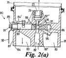
図2(a)は、遠心分離機の変形形態の部分断面図で、異なる形式の弁装置を開弁位置で示した図であり、
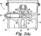
図2(b)は、図2(a)と類似の図で、弁装置を閉弁位置で示した図である。
図1に見られるように、機械10、例えば従来式の設計の内燃機関は、油等の液体潤滑剤により潤滑される可動構成部材を収容するブロック11を有している。潤滑剤は、ブロック11内に鋳造または穴あけされた通路を介してポンプ輸送され、かつまた使用済み潤滑剤を大気圧で溜め又は他のリザーバへ戻すようにされている。供給通路12は、小さい直径を有し、事実上ポンプ圧で液体を受取るように接続された高圧通路であり、排出通路13は、大きい直径を有し、溜め(サンプ:sump)に接続された大気圧排出通路である。通路12,13は、双方とも、事実上平らな、水平の取付け表面14に開口している。取付け表面14には、遠心分離機15が、シールガスケット16を間挿されて取付けられている。
遠心分離機15は、ガスケット16を介して水平の取付け表面14に取付けるようにされた第1表面18と、反対側に位置する第2表面19とを有する基部17を含んでいる。第2表面19は、概ね上向きであり、捕集領域20を形成する凹部を有する。捕集領域20は、破線19′で示したように、図平面外を、第1表面の近くまで延在し、厚い中央領域21にまたがるように形成されている。排出通路22は、基部を貫通して捕集領域20から第1表面18まで延在し、基部が取付けられた状態で、排出通路13に連通する。
スピンドル部材25は静止スピンドルを含み、該スピンドルは、中央領域21で第2表面19に固定され、かつ第2表面から、使用可能な状態、つまり設定された状態で事実上垂直に延在する軸線26に沿って、捕集領域上方に延在している。このスピンドルは、軸線方向に延在するスピンドル通路を有し、通路の一端28は基部に向かって開口し、他端は、横穴29を介してスピンドル壁に開口している。
スピンドルを中心として回転するように、スピンドル上に保持されたロータ30は、スピンドルに沿って、スピンドルを取囲む軸受け管31を含み、該軸受け管は、横穴29を介してスピンドル通路から液体を受取るように構成されている。軸受け管31は、また環状汚染物容器32を保持し、かつその周囲を画定しており、該容器32は、軸受け管の開口33を介してスピンドル通路と液体が流通するように連通し、かつ容器基部に形成された接線方向の反動ノズル部材34を介して、捕集領域20と連通している。
取外し可能なカバー35が、ロータと捕集領域とを包囲しており、外方へ突出し互いに重ねられたシールフランジ35′,17′を介して基部17上に保持されている。シールフランジ35′と17′との間にはシール部材36が配置されている。シールフランジ35′,17′は、半径方向に先細にテーパ付けされ、相応に形付けされた周方向に連続するクランプリング部材37によって包囲されている。クランプリング37は、半径方向の締付けによってシール部材に十分な軸方向密封力を与えるように操作可能である。カバーの上部は、スピンドルの上端25′を包囲し、ナット38の配置により固定され、シール部材36に対しては、制限された軸方向圧力が加えられる。
液体供給通路40は、基部を貫通し、スピンドル通路の端部28と前記第1表面18との間に延在しており、排出通路22と似た形式で、機械ブロックの取付け表面14内の通路12と連通している。
基部17は、また制御弁装置を有している。該制御弁装置は、全体を符号45で示され、その詳細については後述する。
制御弁装置は別にして、遠心分離機の操作は事実上従来式である。排出通路13と排出通路22とは、大きな断面を有し、カバー内と捕集領域内との周囲圧力が機械の溜めと等圧に、つまり大気圧になるように規定する。供給通路12から高圧で送られてくる液体潤滑剤は、基部17に入り、基部17を横切り、スピンドル通路27に沿って、ロータの汚染物容器32内に入る。容器内では、液体圧は事実上供給圧である。液体は、容器から反動ノズル部材34を介して強制的に圧出され、捕集領域20に集められ、そこから排出通路22と排出通路13とを介して排出される。反動ノズル部材の前後の差圧により、容器32を通過する液体からの粒状汚染物分離に必要な高速でロータを回転させる十分な反動が発生させられる。
高圧での液体供給は、完全に基部17内に形成されている供給通路40を介して行われ、偶然的な損傷を受けることはあり得ないことが分かるだろう。
また、この汚染物容器の場合、分離された汚染物が満杯になれば、回転が止む、つまり停止することも分かるであろう。既述のように、遠心分離機は、本来、バイパスモードで作動するため、保守を含む何らかの理由で、作動の中止が必要となっても、そのこと自体は、機械の停止を要しない。したがって、停止したロータからカバーを取外すさい、作業員に危険があるとすれば、ロータが除去された後、恐らく供給圧の結果として、液体が高圧で放出されて作業員と機械とに損傷を与え、恐らく機械の機能部材が潤滑不足となることだけである。
制御弁装置45は、機械が高圧で作動中であるにもかかわらず、基部の供給通路40への液体供給中に同時的にロータを取外し得るように操作可能であり、かつまた符号28のところからスピンドル通路への液体供給を阻止するように操作可能である。この実施例では、制御弁装置は、液体の通過する供給通路を遮断するように操作可能である。
制御弁装置45は弁孔46を含み、該弁孔が、基部の第3表面47から基部を、特に、厚手の中央領域21を貫通して延在し、かつ供給通路40と交差しており、それにより供給通路の部分48を画定している。該部分48は、第1表面18の開口から延びる供給通路の第1区分40′と、該開口からスピンドル通路へ延びる供給通路の第2区分40″との間に、弁孔の軸線49に沿って延在している。
弁体50は、弁孔に沿って延在し、液体をスピンドル通路へ通過させ得る開弁位置(図示の位置)と、スピンドル通路への液体供給を遮断する閉弁位置との間を、弁孔に対し移動可能である。
弁孔と弁体とは断面が円形であり、弁体は、共通の長手軸線49を中心として回転して、開弁位置との閉弁位置との間を変位することができる。弁体は、弁孔内に配置されることで、供給通路第1区分40′を供給通路部分48から遮断するようになっており、また弁体内部には、軸方向に延びる穴51の形式の通路と、第1区分40′と整合する横開口52とを備えており、これにより、図示の回転位置では、弁体が、供給通路部分48と第2区分40″への液体の自由通過を可能にし、他の回転位置では、供給通路を遮断する。
弁体の端部55は、基部の第3表面47のところで弁孔から突出し、弁体を回転可能に変位させ得る手段、すなわちハンドル部材56が、前記端部に固定され、手動による弁体の変位を可能にしている。
ハンドル部材を操作して、弁体を閉弁位置へ回転させることによって、スピンドル通路への液体供給がカバー35位置で阻止され、ロータ32が安全に取外せることが分かるだろう。
ロータが単に停止しただけで、その停止が制御弁装置の操作の結果でない場合に、カバーを誤って取外すことがないように、制御弁装置によるスピンドル通路への液体供給時に、つまり弁体50が開弁位置を占めている時のカバーの取外しを防止するため、全体を符号60で示したインターロック装置60が備えられている。
この目的のために、カバーは、好ましくは、カバーのクランプリング部材37によって符号61のところに形成される突出部を有し、またクランプリング部材37は上向きの肩を形成している。ハンドル部材56は、前記突出部の位置よりも上方へ弁体から延在し、変位可能の当付け部材62を保持し、該当付け部材が前記肩に重なるように配置されている。当付け部材とハンドル部材とを含むインターロック装置は、したがって、クランプリング部材の半径方向拡張と、カバーの上方への取外しとを阻止する機能を有しており、前記拡張と取外しが可能になるには、ハンドル部材を旋回させて当付け部材を当付け位置から移動させ、かつ弁体を開弁位置から変位させなければならない。当付け部材は、ハンドル部材の旋回が突出部への当付けを解除するだけで、それ以上の動作を生じさせないという意味で受動式にすることができるが、好ましくは、前記当付け関係を終了させる手動操作が、開弁位置からの弁体の移動を阻止する付加的効果を有するようにするか、または意図的操作なしに、弁体を閉弁位置へ移動させ得るようにするのが好ましい。
制御弁装置45は、図示のように、任意に、あらかじめ定められた最低水準を下回る液圧に応動するカットオフ弁70を含むことにより、スピンドル通路からの液体の流出を防止できる。最も好ましいのは、該カットオフ弁を基部内に配置し、供給通路40を遮断することである。図示のように、カットオフ弁70は、弁孔46内に配置され、ピストン71を有しており、該ピストン71は、弁孔に沿って延在し、供給通路の第2区分40″の端部の下に位置し、ばね72によって弁体方向へ付勢され、肩73によって止められている。ピストンは、ばね72の付勢を克服するのに必要な前記最低水準を超える液圧に応動して変位し、液体は弁体のところを通過してスピンドル通路へ流入する。供給圧が回転維持には低すぎる場合、液体潤滑剤がロータを通過しないように、かつまた潤滑経路をバイパスしないように、この種のカットオフ弁を使用すること自体は、周知である。本発明のこの実施例では、弁体自体に対し強力なシール圧力が加えられることなしに弁体が閉弁位置にある場合、カットオフ弁によって、スピンドル通路への液体流入に対する効果的なシールを得ることもできる。言い換えると、弁体が、弁体前後に適当な差圧が生じるのに十分な閉鎖性を有している場合には、弁体を通過するいくらかの漏れが許容でき、カットオフ弁により密封効果が示される。
カットオフ弁、インターロック装置等の特徴を有する形式にも、有しない形式にも、また該特徴を有する場合、該特徴が取り得るさまざまな形式についても、多くの変化形が可能であることは理解できよう。供給液体が弁体とカットオフ弁とに出会う順序についても、それらの相対配置は逆でもよい。
同じように、手動式、動力機構式を問わず、また変位または移動の性質が、回転ではなく直線的であるか、回転に加えて直線的であるかを問わず、弁体を移動させる手段に関しても、変化形が可能である。例えば、弁体の並進、回転いずれの能力も、インターロック装置に組込むことができ、それにより、当付け部材とハンドル部材とは、突出当付け位置から弁孔軸線49に沿って変位させることができる一方、該当付け位置からハンドル部材を旋回させることで、弁体を安定的な閉弁位置に移動させることができる。
前記実施例の場合、制御弁装置は、遠心分離機によって生ぜしめられるバイパス回路を液体が通過するのを、簡単な操作で阻止できる。ある事情の場合には、機械10のあらゆる部材への液体供給圧を、種々の流路で生じる抵抗にしたがって相互に関連させるのがよく、供給通路を単純に遮断することによって、相互の関連を断つことは望ましくないだろう。
図2(a)と図2(b)とは、第2形式の遠心分離機80を部分的に示したものであり、既述の部材で図示されていないものや、完全には図示されていないものもある。
基部81は、既出の基部17と細かい点が異なっており、特に、供給通路82が中心に設けられ、該供給通路の周囲に同軸的に排出通路83が設けられている点が異なっている。両通路は、操作可能に下向きの、水平の第1表面84に開口しており、基部の反対側には上向きの第2表面84′が備えられている。
全体を符号85で示した制御弁装置は、弁孔86を含み、該弁孔は、第3表面87から基部内へ延在し、供給通路と交差し、弁孔の幅により弁孔部分88を画定している。
弁孔内には、弁孔軸線方向に延在し、部分88を貫通する回転可能な弁体90が配置され、該弁孔部分88は、供給通路と交差し、基部第3表面外側の端部91で終わっている。この端部には、ハンドル92が取付けられている。
弁孔部分88により、供給通路は、第1表面84と連通させる区分82′と、スピンドル通路と連通する区分82″とに分割される。また分岐通路95が、基部内に形成され、弁孔を排出通路83と接続している。
弁体90は、貫通横孔96を有し、該貫通横孔が、図2(a)に示した弁体開弁位置では、供給通路の区分82′,82″を連通させ、垂直平面内にノッチ97を有している。該ノッチは、図2(b)に示した弁体閉弁位置では、供給通路区分82′を分岐通路95と連通させる。
この構成の遠心分離機80の場合、弁体が閉弁位置へ移動しても、液体は、遠心分離機により提供されるバイパス回路へ流入し続けるが、排出通路へ直接に戻されるため、カバーおよびロータの取外しが可能である。
この実施例は、また、回転運動ではなく並進運動を行うか、回転運動に加えて並進運動を行うように構成された弁体を有することもできる。さらにまた、弁装置のカバーの偶発的な除去および/または弁装置の偶発的な操作を防止するために、インターロック装置を含むこともでき、あるいはまた、もしくはそれに加えて、カットオフ弁を備えて、ロータへの低圧液体供給を防止することも可能である。
分岐通路が設けられていることで、弁体が閉弁位置にある場合、スピンドル通路への液体漏れを防止するための効果的シール機構の要求が緩和される。供給通路の2つの区分82′,82″を、適当であれば圧力応答カットオフ弁を介して、恒常的に接続させることも可能であり、閉弁位置での流れの分岐を介しての減圧に頼ることにより、スピンドル通路への液体供給を阻止することができる。
弁装置または弁装置部分を基部内部とは別のところ、すなわち基部から離れて配置された部材、または基部から延在するスピンドル部材内に配置してもよい。
本発明による遠心分離機と一緒に用いられる機械の取付け表面は、言うまでもなく水平でなくともよいので、基部の第1表面は水平でなくてもよく、第2表面に対して反対側でなくてもよい。
さらに、第1表面は操作可能に配向されていても、排出通路および/または供給通路は、いずれも第1表面18または84位置で機械に接続するために、外部に現れている必要はなく、該第1表面を介して、基部は、機械に対して、かつまた取付け表面内の対応通路と連通するように整合された通路に対し操作可能に取付けられる。The present invention relates to a liquid cleaning apparatus of a type including a centrifuge that separates solid contaminants from a liquid that passes through a liquid container that rotates at a high speed. It relates to installation and maintenance on the machine.
It is well known to remove solid contaminants of any size from a fluid (usually often a liquid) with a centrifuge. In the centrifuge, a high-speed motor arranged vertically in nature has a contaminant settling container (conveniently referred to simply as a contaminant container) through which fluid passes and is solid in the container. Contaminants are separated from the fluid and settled on the container wall, and the contaminants are periodically removed from the container wall or the container is replaced. This type of centrifugal cleaning device can have a rotor driven externally connected to an engine or similar rotating device used together, which results in a complex and expensive configuration . Alternatively, and more commonly seen, the centrifugal cleaning device is driven by discharging fluid that is sent to the contaminant container under pressure through a tangential nozzle member, and in response the rotor Is a form that rotates at high speed essential for effective centrifugation. This type of fluid cleaning device that drives the rotor using the fluid to be cleaned is referred to herein as a self-powered centrifuge.
This self-powered centrifuge is used with various types and sizes of internal combustion engines to separate particulate contaminants from lubricating oil circulating through the engine components through passages formed in the engine block. Examples of this type of cleaning device can be found in GB-735658, GB-1089355, GB-2193123.
A self-powered centrifuge, by definition, is a bypass device through which a lubricating oil supplied at a pressure substantially equal to that supplied to other engine components passes. Lubricant loses all of its energy while passing, causing the container to rotate and return to the engine's collection reservoir by gravity. This centrifuge is therefore always used in combination with a conventional full flow barrier filter, through which the lubricating oil is pumped at high pressure to the engine's working components. A certain percentage of the lubricating oil is directed to the centrifugal cleaning device.
Conventionally, when manufacturing an engine block, an area for receiving the filter assembly is provided, and a passage for supplying and removing the lubricant to the filter assembly is provided so as to appear on the surface of the area. Yes. Due to the small engine block surface area to which the additional centrifuge can be mounted, so far the emphasis has been on obtaining a maximum cross-sectional area for the discharge passage so that the lubricant can be discharged freely under gravity, On the other hand, the supply of high pressure was made via an externally exposed conduit.
It is known to integrate a full-flow barrier filter and a self-powered centrifuge into a single assembly structure with a carrier manifold or carrier block to create a cleaning assembly. The manifold or block is attached to the engine block and forms an interface between the engine block and the fluid passage. Examples of these are shown in GB-866299, GB-2160449, GB-2160796. However, for many engine designs with current simple full-flow filters, it is preferable to separate the full-flow filter and the centrifuge.
One advantage of using a centrifuge is that the contaminant container can be used for an extended period of time until it is filled with sediment and requires cleaning or replacement. However, its use is not essential for continuous use of the engine for at least a short period of time by bypassing the lubricant to the engine's operating components, but again with conventional engine structures, at regular maintenance times It is necessary to stop the engine and clean or replace the pollutant container. Although the centrifuge container does not necessarily require maintenance, in such a case, removal of the cover surrounding the container, sealing, etc. Exchange is required.
Because the lubricant path through the device is a bypass that supplies lubricant to the engine components, the contaminant container must be capable of removal, cleaning, replacement or all other measures during engine operation. However, when the contaminant container is rotating at high speed and jetting lubricant in the cover, it is clear that this measure is highly undesirable. In addition, it is usually easy to detect when the deposit is full and the contaminant container has stopped, ie, when it has stopped rotating, so that the operator can use the container's inlet to supply high-pressure lubricant for the engine. There is a possibility of removing the cover and taking out the stationary container without noticing that it is connected to or forgetting it. If such inadvertent removal of the rotor is performed, not only will the lubricant be released outside the engine, but the engine components will need more lubricant that would normally be bypassed by the centrifuge. Become.
The risk that uncontrolled release of lubricant poses to engine functionality is, of course, a compromise solution at the expense of damaging the high pressure liquid supply line exposed outside the engine.
Therefore, this type of self-powered centrifuge is used without maintenance for a long time, but its use may cause engine damage due to accidental or inadvertent operation unrelated to the functioning of the separator itself. This includes a small but quantifiable risk.
The engine is merely an example of a machine in which a liquid such as a lubricant is circulated by a pump pressure and requires separation of particulate contaminants. The object is to obtain a self-powered centrifuge for a machine that is circulated through a source and a discharge passage, which also has improved operational functionality and safety over conventional configurations.
According to a first aspect of the present invention, a self-powered centrifuge for separating solid contaminants from a liquid lubricant, also on the mounting surface of a machine in which the liquid lubricant is circulated by a pump from a reservoir. A centrifuge adapted to be operably mounted,
i) including a base, the base having a first surface and a second surface, wherein the first surface is adapted to be mounted in a workable arrangement relative to the mounting surface of the machine, and thus With the attached first surface, the second surface is positioned so as to be generally upward relative to the first surface;
ii) including a liquid discharge passage, the liquid discharge passage extending through the base and extending in the second surface from the collection region to a surface different from the second surface;
iii) a spindle passage that includes a spindle member that extends from the second surface of the base above the collection region and is usable along a substantially vertical axis and extends axially; Have
iv) including a rotor, the rotor being held on the spindle member for rotation about the spindle member and having an annular contaminant container, the contaminant container being in communication with the spindle passage; The contaminant container communicates with the collection area via the reaction nozzle member, and the contaminant container receives the liquid lubricant pumped at a high pressure from the spindle member and reacts with the liquid lubricant to react with the reaction nozzle. Operable to discharge through the member, the operation causing rotation about the spindle member at a rate capable of separating the solid contaminant from the liquid lubricant within the contaminant container;
v) includes a removable cover that is supported on the base and encloses the rotor and collection area;
vi) including a liquid lubricant supply passage, the supply passage extending through the base and between the spindle passage and another surface different from the second surface;
vii) including a control valve device, which is operable to allow simultaneous removal of the rotor when the liquid lubricant is pumped at the high pressure into the supply passage in the base. .
According to a second aspect of the present invention, a machine in which liquid is circulated includes a pumping device for creating a circulating pressure in the liquid, a mounting surface, and a previously defined centrifuge mounted on the mounting surface. Including separators.
According to a preferred mechanical configuration, the mounting surface includes a liquid supply passage and / or a discharge passage, and the centrifuge is coupled to the mounting surface along with a supply passage and / or a discharge passage communicating with a corresponding passage in the mounting surface. Installed.
Next, specific examples of the present invention will be described with reference to the accompanying drawings.
FIG. 1 is a cross-sectional view of a portion of a machine through which lubricant circulates, which machine includes a high pressure supply passage and a low pressure discharge passage that are open to a substantially horizontal mounting surface, and a centrifuge according to the present invention. And the centrifuge is attached to the mounting surface via a base having a liquid shut-off valve device.
FIG. 2 (a) is a partial cross-sectional view of a modified form of the centrifuge, showing a different type of valve device in the valve open position,
FIG. 2B is a view similar to FIG. 2A and showing the valve device in the closed position.
As can be seen in FIG. 1, a machine 10, such as an internal combustion engine of conventional design, has a
The
The
A
A
A
The base 17 also has a control valve device. The control valve device is generally indicated by
Apart from the control valve device, the operation of the centrifuge is virtually conventional. The
It will be appreciated that the liquid supply at high pressure is through the
It will also be seen that in the case of this contaminant container, the rotation stops, i.e. stops when the separated contaminants are full. As described above, since the centrifuge originally operates in the bypass mode, even if it is necessary to stop the operation for some reason including maintenance, the centrifuge itself does not require the machine to be stopped. Therefore, if the cover is removed from a rotor that has stopped and there is a danger to the operator, after the rotor has been removed, liquid may be released at high pressure, possibly as a result of the supply pressure, causing damage to the operator and the machine. Given, perhaps only because the functional parts of the machine are under-lubricated.
The
The
The valve body 50 extends along the valve hole, and has a valve position between a valve open position (shown position) where liquid can pass through the spindle passage and a valve closing position where the liquid supply to the spindle passage is shut off. It is movable with respect to the hole.
The valve hole and the valve body are circular in cross section, and the valve body can be rotated about a common longitudinal axis 49 to be displaced between the valve opening position and the valve closing position. The valve body is arranged in the valve hole so as to block the supply passage
The
It will be appreciated that by manipulating the handle member to rotate the valve body to the closed position, liquid supply to the spindle passage is blocked at the
In order to prevent the cover from being accidentally removed when the rotor is simply stopped and is not the result of operation of the control valve device, the valve body 50 is not supplied when the control valve device supplies liquid to the spindle passage. In order to prevent the cover from being removed when it occupies the valve open position, an
For this purpose, the cover preferably has a protrusion formed at 61 by the
As shown in the figure, the
It is possible that many variations are possible for the various types that the feature can take, whether it has a feature, such as a cut-off valve, an interlock device, etc. I understand. Regarding the order in which the supply liquid meets the valve body and the cutoff valve, their relative arrangement may be reversed.
Similarly, means for moving the valve element regardless of whether it is a manual type or power mechanism type, and whether the nature of the displacement or movement is linear instead of rotation or linear in addition to rotation. Variations are also possible. For example, both translational and rotational capabilities of the valve body can be incorporated into the interlock device, so that the contact member and the handle member can be displaced along the valve hole axis 49 from the protruding contact position. On the other hand, the valve body can be moved to a stable valve closing position by turning the handle member from the corresponding attachment position.
In the case of the above embodiment, the control valve device can prevent the liquid from passing through the bypass circuit generated by the centrifuge with a simple operation. In some circumstances, the liquid supply pressure to all components of the machine 10 may be related to each other according to the resistances that occur in the various flow paths, and the connection is made simple by simply blocking the supply passages. It would not be desirable to refuse.
2 (a) and 2 (b) are partial views of the
The
The control valve device, indicated generally at 85, includes a
A
By the
The
In the case of the
This embodiment can also have a valve body configured to perform a translational motion rather than a rotational motion, or to perform a translational motion in addition to the rotational motion. Furthermore, an interlock device may be included to prevent accidental removal of the valve device cover and / or accidental operation of the valve device, and / or in addition thereto, a cut-off valve is provided. Thus, it is possible to prevent the low pressure liquid from being supplied to the rotor.
By providing the branch passage, the requirement of an effective sealing mechanism for preventing liquid leakage to the spindle passage is eased when the valve body is in the valve closing position. It is also possible for the two
The valve device or valve device portion may be arranged separately from the inside of the base, i.e. in a member arranged away from the base or in a spindle member extending from the base.
The mounting surface of the machine used with the centrifuge according to the present invention need not be horizontal, so the first surface of the base may not be horizontal and not opposite the second surface. Also good.
Further, even though the first surface is operatively oriented, neither the discharge passage and / or the supply passage need be exposed to the outside in order to connect to the machine at the
Claims (8)
i) 基部(17)が含まれ、該基部が、第1表面(18)と第2表面(19)とを有し、前記第1表面(18)が、前記機械(10)の取付け表面に対し作業可能な配置で取付けられるようにされ、また、このように取付けられた前記第1表面と共に、前記第2表面(19)が、前記第1表面に対して概ね上向きに位置するように配置されており、
ii) 液体排出通路(22,83)が含まれ、該液体排出通路が、基部を貫通して、前記第2表面内を捕集領域から前記第2表面とは別の表面まで延在しており、
iii) スピンドル部材(25)が含まれ、該スピンドル部材が、前記基部の前記第2表面から前記捕集領域の上方へ、使用可能に事実上垂直の軸線(26)に沿って延在し、かつ軸線方向に延在するスピンドル通路を有しており、
iv) ロータ(30)が含まれ、該ロータが、前記スピンドル部材を中心として回転するように前記スピンドル部材上に保持され、かつ環状の汚染物容器(32)を有しており、該汚染物容器が、スピンドル通路と連通し、かつ反動ノズル部材を介して前記捕集領域と連通しており、さらに前記汚染物容器は、上昇圧力下でポンプ輸送される前記液体潤滑剤を前記スピンドル部材から受取ると、それに応動して、潤滑剤を反動ノズル部材を介して放出するように操作可能であり、該操作によって、前記汚染物容器内で液体潤滑剤から前記固体汚染物が分離できる速度で前記スピンドル部材を中心とする回転が生じ、
v) 取外し可能のカバー(35)が含まれ、該カバーが、前記基部上に支えられ、前記ロータと捕集領域とを包んでおり、
vi) 液体潤滑剤供給通路(40,82)が含まれ、該供給通路が前記基部を貫通して、前記スピンドル通路(27)と前記第2表面とは別の表面(18,84)との間に延在しており、
vii) 制御弁装置(45,85)が含まれ、該制御弁装置が、弁孔(46,86)と弁体(50,90)とを有しており、
前記弁孔(46,86)が、前記供給通路と交差し、基部を貫通して延在し、かつ前記供給通路の部分(48,88)を規定しており、また
前記弁体(50,90)が、前記弁孔に沿って延在し、かつ、開弁位置と閉弁位置との間で前記弁孔に対して移動可能であり、前記開弁位置では、前記制御弁装置が、上昇圧力下でポンプ送りされる液体潤滑剤の前記スピンドル通路への自由通過を許し、前記閉弁位置では、前記制御弁装置が、前記スピンドル通路への液体の供給を阻止して、前記基部内の前記供給通路(40′,82′)へ前記上昇圧力下でポンプ送りされる液体潤滑剤の前記供給と同時にロータの取外しを許すようになっていることを特徴とする自己動力式遠心分離機。 A self-powered centrifuge (15,80) for separating solid contaminants from a liquid lubricant, wherein the liquid lubricant is pumped from a reservoir, wherein the liquid lubricant is operatively mounted to a mounting surface of the machine (10). In the form of being circulated by transportation,
i) contains a base (17), the base portion has a first surface (18) and a second surface (19), said first surface (18), the intake with the surface of the machine (10) It is to be mounted in a workable arrangement with respect to, and thus together with the attached first surface, said second surface (19), so as to be positioned upward I GENERAL relative to the first surface Are located in
ii) it contains a liquid discharge passage (22,83) is, liquid discharge passage, through the base portion, extending the second inner surface from the collection region to another surface and the second surface And
iii) the spindle member (25) includes, the spindle member, from the second surface of the base to above the collecting area extends along the axis virtually perpendicular to enable (26), And a spindle passage extending in the axial direction,
iv) includes a rotor (30), said rotor, said retained on the spindle member for rotation about a spindle member, and has an annular pollution Monoyo device (32), said contamination object container communicates with the spindle passage, and communicates with the collecting area through a reaction nozzle member, further wherein the contaminant container, the spindle member said liquid lubricant is pumped under elevated pressure Upon receiving from it in response, the lubricant is operable to to emit through the reaction nozzle member, by the manipulation, the solid contaminants from a liquid lubricant at the contaminant container at a rate that can be separated rotation occurs around the spindle member,
v) contains a removable cover (35), the cover is supported on the base, and wrapped with the rotor and collection region,
vi) contains a liquid lubricant supply passage (40,82) is in the feed passage through said base, said spindle passage (27) and with another surface (18,84) and the second surface Extending in between
vii) includes a control valve device (45, 85), the control valve device having a valve hole (46, 86) and a valve body (50, 90);
The valve holes (46, 86) intersect the supply passage, extend through the base and define portions (48, 88) of the supply passage; and
The valve body (50, 90) extends along the valve hole and is movable with respect to the valve hole between a valve opening position and a valve closing position. In the valve opening position, The control valve device allows free passage of liquid lubricant pumped under elevated pressure to the spindle passage, and in the closed position, the control valve device prevents liquid supply to the spindle passage. The rotor is allowed to be removed simultaneously with the supply of the liquid lubricant pumped under the rising pressure to the supply passages (40 ', 82') in the base. Self-powered centrifuge.
前記弁体(50,90)が、前記弁孔(46,86)内に配置されることにより、前記弁体の前記開弁位置および閉弁位置の両位置で、前記供給通路の部分(48,88)と前記基部の第1表面(18,84)との間の前記供給通路(40,82)を遮断し、前記弁体(50,90)が、前記開弁位置で前記供給通路(40′,82′)とスピンドル通路(27)とを連通させるように操作可能な、少なくとも1つの通路(51,52;96)を弁体内部に有することを特徴とする遠心分離機。Self-powered centrifuge (15, 80) according to claim 1 ,
Said valve element (50, 90), by being disposed in the valve hole (46,86) in at both position before KiHiraki valve position and closed position location of said valve body, part of the supply passage and the blocking of the supply passage (40,82) between the (48,88) and the first surface of the base portion (18,84), said valve body (50, 90) is, the supply in the open position A centrifugal separator characterized by having at least one passage (51, 52; 96) inside the valve body operable to communicate the passage (40 ', 82') and the spindle passage (27).
前記弁体の一方の端部(55,91)が、前記基部の第3面(47,87)位置で前記弁孔(46,86)から突出しており、また、前記弁体が前記端部によって変位可能であり、前記インターロック装置(60)が、上向きの肩を成す前記カバー(35)の突出部(61)と、前記肩の上に位置づけられた変位可能な当付け装置(62)とを含んでおり、この当付け装置により前記基部(17)からの前記カバーの取外しが阻止され、前記当付け装置は、前記弁体(55)の前記端部に結合されており、もって前記肩の上の位置からの前記当付け位置の変位が、前記開弁位置からの前記弁体(50)の変位と関連づけられていることを特徴とする遠心分離機。Self-powered centrifuge (15) according to claim 3 ,
One end portion (55, 91) of the valve body protrudes from the valve hole (46, 86) at the position of the third surface (47, 87) of the base portion, and the valve body is the end portion. is displaceable by the interlock device (60) is protruded portion of an upward shoulder formed to said cover (35) and (61), displaceable abutment device was Ichizukera on said shoulder ( 62) and includes a, the abutment removal of said cover from said base portion (17) by the device is prevented, the abutment device is coupled to the said end of the valve body (55), centrifuge with displacement of the abutment position location from the position of the top of the shoulder, characterized in that associated with the displacement of the valve body (50) from said open position.
前記弁体(50)が前記開弁位置を占めている場合には、前記ハンドル部材(56)が、前記カバーの前記突出部(61)の位置より上方に、前記弁体(51)の前記端部から延在しており、前記インターロック装置(60)の、変位可能な前記当付け装置(62)が前記ハンドル部材(56)を有していることを特徴とする遠心分離機。Self-powered centrifuge (15) according to claim 4 ,
When said valve element (50) occupies said open position, said handle member (56) is above the position of the projecting portion of said cover (61), the said valve body (51) extends from the end portion, the interlock device (60), the centrifuge displaceable wherein the abutment device (62), characterized in that it has the handle member (56).
前記弁孔(46)が、前記弁孔の軸線(49)に沿って延在する前記供給通路部分(48)を規定しており、前記弁体(50)が、前記開弁位置を占めることにより、軸線方向に延びる前記弁孔部分へ液体を供給するように構成されており、前記カットオフ弁(70)がピストン(71)を含んでおり、該ピストンが、前記弁孔に沿って延在し、かつ前記弁体方向へ付勢されることにより、前記スピンドル通路を前記弁孔から遮断しており、前記最低水準を超える液圧に応動して、付勢部材(72)の力に抗して液体を前記スピンドル通路へ流入させ得ることを特徴とする遠心分離機。Self-powered centrifuge (15) according to claim 6 ,
Wherein the valve hole (46), said and valve hole axis (49) the supply passage portion extending along the (48) with provisions, the valve body (50) occupies said open position Accordingly, the liquid is supplied to the valve hole portion extending in the axial direction, and the cut-off valve (70) includes a piston (71), and the piston extends along the valve hole. It extends, and by being urged to the valve body direction, the spindle passage is blocked from the valve hole, in response to fluid pressure exceeding the minimum level, the force of the biasing member (72) A centrifugal separator characterized in that a liquid can flow into the spindle passage against the above.
前記基部(17,81)の前記第1表面(18,84)が、前記第2表面(19,84′)に対して事実上反対の側にあり、前記供給通路(40,82)が、前記基部の前記第1表面(18,84)に対して開放され、前記排出通路(22,83)もまた前記基部の前記第1表面(18,84)に対して開放されていることを特徴とする遠心分離機。Self-powered centrifuge (15, 80) according to any one of claims 1 to 7 ,
Wherein the first surface of the base portion (17,81) (18,84) is located on the side of the virtually opposite to said second surface (19,84 '), the supply passage (40,82) is, is opened for the first surface of the base portion (18,84), said discharge passage (22,83) said is released to open for the first surface (18,84) of the base which tossed Centrifuge characterized by.
Applications Claiming Priority (3)
| Application Number | Priority Date | Filing Date | Title |
|---|---|---|---|
| GB9605735A GB2311239B (en) | 1996-03-19 | 1996-03-19 | Centrifugal liquid cleaning arrangement |
| GB9605735.1 | 1996-03-19 | ||
| PCT/GB1997/000619 WO1997034703A1 (en) | 1996-03-19 | 1997-03-07 | Centrifugal liquid cleaning arrangement |
Publications (3)
| Publication Number | Publication Date |
|---|---|
| JP2000506775A JP2000506775A (en) | 2000-06-06 |
| JP2000506775A5 JP2000506775A5 (en) | 2004-12-02 |
| JP3917663B2 true JP3917663B2 (en) | 2007-05-23 |
Family
ID=10790640
Family Applications (1)
| Application Number | Title | Priority Date | Filing Date |
|---|---|---|---|
| JP53321597A Expired - Lifetime JP3917663B2 (en) | 1996-03-19 | 1997-03-07 | Centrifugal liquid cleaning equipment |
Country Status (9)
| Country | Link |
|---|---|
| US (1) | US6074336A (en) |
| EP (1) | EP0889752B1 (en) |
| JP (1) | JP3917663B2 (en) |
| AT (1) | ATE217545T1 (en) |
| AU (1) | AU2100697A (en) |
| DE (2) | DE69712612D1 (en) |
| GB (1) | GB2311239B (en) |
| WO (1) | WO1997034703A1 (en) |
| ZA (1) | ZA972277B (en) |
Families Citing this family (25)
| Publication number | Priority date | Publication date | Assignee | Title |
|---|---|---|---|---|
| GB9711164D0 (en) * | 1997-05-31 | 1997-07-23 | Agco Limited | Vehicle transmission lubrication system |
| GB9726336D0 (en) * | 1997-12-13 | 1998-02-11 | Glacier Metal Co Ltd | Control valve arrangement for a centrifugal liquid arrangement |
| GB2351249A (en) | 1999-06-23 | 2000-12-27 | Federal Mogul Engineering Ltd | Safety mechanism for liquid centrifuge |
| US6602180B2 (en) | 2000-04-04 | 2003-08-05 | Fleetguard, Inc. | Self-driven centrifuge with vane module |
| US6652439B2 (en) | 2000-04-04 | 2003-11-25 | Fleetguard, Inc. | Disposable rotor shell with integral molded spiral vanes |
| US6551230B2 (en) * | 2000-04-04 | 2003-04-22 | Fleetguard, Inc. | Molded spiral vane and linear component for a centrifuge |
| US6599229B1 (en) * | 2002-02-27 | 2003-07-29 | Fleetguard, Inc. | Air-assisted drain with pressure cutoff valve |
| US6793615B2 (en) * | 2002-02-27 | 2004-09-21 | Fleetguard, Inc. | Internal seal for a disposable centrifuge |
| DE20213786U1 (en) * | 2002-09-04 | 2004-02-12 | Hengst Gmbh & Co.Kg | Centrifuge for cleaning lubricating oil of an internal combustion engine |
| GB2406893B (en) * | 2003-10-08 | 2007-02-14 | Mann & Hummel Gmbh | Centifrugal separation apparatus and control valve arrangement therefor |
| DE502005003992D1 (en) * | 2004-03-17 | 2008-06-19 | Hengst Gmbh & Co Kg | STAINLESS STEEL CENTRIFUGE FOR CLEANING THE LUBRICATING OIL OF AN INTERNAL COMBUSTION ENGINE |
| DE202004017820U1 (en) * | 2004-11-17 | 2006-03-23 | Hengst Gmbh & Co.Kg | Free flow centrifuge for cleaning of internal combustion engine lubricating oil has inlet flow splitter and rotor with return nozzle for one flow and contaminant collector for second flow |
| US7393317B2 (en) * | 2005-04-11 | 2008-07-01 | Cummins Filtration Ip, Inc. | Centrifuge rotor-detection oil-shutoff device |
| GB2425077B (en) * | 2005-04-15 | 2009-11-18 | Mann & Hummel Gmbh | Centifrugal separator and rotor therefor |
| US8021290B2 (en) * | 2007-11-26 | 2011-09-20 | Honeywell International Inc. | Oil centrifuge for extracting particulates from a fluid using centrifugal force |
| GB2465374A (en) * | 2008-11-14 | 2010-05-19 | Mann & Hummel Gmbh | Centrifugal separator with venturi |
| GB2478578A (en) * | 2010-03-11 | 2011-09-14 | Mann & Hummel Gmbh | Centrifugal separator with protected bearing |
| CN103557425B (en) * | 2013-11-05 | 2016-08-17 | 江苏科雷斯普能源科技股份有限公司 | The super fine filter of disc type list filter core |
| RU2542620C1 (en) * | 2014-02-18 | 2015-02-20 | Федеральное государственное бюджетное образовательное учреждение высшего профессионального образования Волгоградский государственный аграрный университет | Centrifugal oil filter |
| KR101465022B1 (en) * | 2014-05-12 | 2014-11-27 | 이상필 | Purification apparatus for compressed air |
| KR102483005B1 (en) | 2015-04-08 | 2022-12-29 | 만 운트 훔멜 게엠베하 | centrifuge |
| RU2611116C1 (en) * | 2015-10-06 | 2017-02-21 | федеральное государственное бюджетное образовательное учреждение высшего образования "Волгоградский государственный аграрный университет" (ФГБОУ ВО Волгоградский ГАУ) | Spin oil filter |
| CN106140492B (en) * | 2016-08-26 | 2018-04-17 | 镇江市长江机电设备厂有限公司 | A kind of centrifugal oil purifier lazy-tongs |
| GB2569167B (en) | 2017-12-08 | 2020-10-14 | Mann & Hummel Gmbh | Filter assembly having a valve movable between closed and open configurations |
| KR102562109B1 (en) * | 2021-11-26 | 2023-08-02 | 신흥정공(주) | Rotor assembly of centrifugal oil cleaner |
Family Cites Families (30)
| Publication number | Priority date | Publication date | Assignee | Title |
|---|---|---|---|---|
| GB278161A (en) * | 1926-09-11 | 1927-10-06 | Albion Motor Car Co Ltd | Improvements in forced lubrication systems for internal combustion engines |
| GB386465A (en) * | 1932-02-29 | 1933-01-19 | Felix Mueller | Method of, and apparatus for, operating centrifugal machines |
| US2373349A (en) * | 1942-07-04 | 1945-04-10 | Sharples Corp | Oil purifying and cooling system |
| GB735658A (en) * | 1953-01-09 | 1955-08-24 | Glacier Co Ltd | Improvements in or relating to centrifugal separator installations |
| GB876299A (en) * | 1958-12-11 | 1961-08-30 | Glacier Co Ltd | Filtering apparatus |
| DE1151222B (en) * | 1960-04-28 | 1963-07-04 | Mann & Hummel Filter | Centrifugal cleaner for liquids, especially for lubricating oils |
| SU145089A1 (en) * | 1961-02-14 | 1962-01-01 | Ю.А. Кудинов | Fuel centrifuge |
| GB1089355A (en) * | 1965-09-22 | 1967-11-01 | Glacier Co Ltd | Centrifugal fluid cleaners |
| GB1390768A (en) * | 1971-04-27 | 1975-04-16 | Glacier Metal Co Ltd | Centrifugal separator |
| US4032451A (en) * | 1975-03-31 | 1977-06-28 | Rosaen Nils O | Filter device with rotatable bypass valve |
| US3982520A (en) * | 1975-08-14 | 1976-09-28 | Wheeler Bill L | Oil filter mounting means |
| US4106689A (en) * | 1977-04-06 | 1978-08-15 | The Weatherhead Company | Disposable centrifugal separator |
| US4165032A (en) * | 1977-06-17 | 1979-08-21 | Dana Corporation | Disposable centrifugal separator with baffle means |
| US4221323A (en) * | 1978-12-07 | 1980-09-09 | The Glacier Metal Company Limited | Centrifugal filter with external service indicator |
| US4379053A (en) * | 1981-06-12 | 1983-04-05 | Brane Earl P | Filter bypass valve assembly |
| US4492631A (en) * | 1982-01-19 | 1985-01-08 | Ae Plc | Centrifugal separator |
| US4498898A (en) * | 1982-04-16 | 1985-02-12 | Ae Plc | Centrifugal separator |
| GB2120134B (en) * | 1982-04-16 | 1985-09-11 | Ae Plc | Centrifugal separator |
| DE3308368C1 (en) * | 1983-03-09 | 1984-04-19 | Erwin 7611 Nordrach Junker | Lid |
| SU1158242A1 (en) * | 1983-07-13 | 1985-05-30 | Ленинградский Ордена Трудового Красного Знамени Институт Водного Транспорта | Reactive centrifuge for cleaning oil |
| US4557831A (en) * | 1984-04-12 | 1985-12-10 | Mack Trucks, Inc. | Centrifugal filter assembly |
| EP0254256B1 (en) * | 1986-07-23 | 1994-03-30 | Pathold Investments Company Limited | Bags |
| GB8618006D0 (en) * | 1986-07-23 | 1986-08-28 | Ae Plc | Centrifugal oil filter |
| GB8711007D0 (en) * | 1987-05-09 | 1987-06-10 | Ae Plc | Centrifugal filters |
| GB9105582D0 (en) * | 1991-03-15 | 1991-05-01 | Glacier Metal Co Ltd | Improved filters |
| GB2259869B (en) * | 1991-09-27 | 1994-10-26 | Pall Corp | Filter units |
| DE4311906A1 (en) * | 1993-04-10 | 1994-10-13 | Audi Ag | Device for ventilation of the crankcase of an internal combustion engine |
| FR2725917B1 (en) * | 1994-10-19 | 1997-11-21 | Moatti Filtration | ASSEMBLY FOR TREATING A FLUID BY FILTRATION AND CENTRIFUGATION |
| GB9500571D0 (en) * | 1995-01-12 | 1995-03-01 | Glacier Metal Co Ltd | Fluid circulation centrifugal cleaner |
| GB9502055D0 (en) * | 1995-02-02 | 1995-03-22 | Glacier Metal Co Ltd | Liquid cleaning system including back-flushing filter and centrifugal cleaner therefor |
-
1996
- 1996-03-19 GB GB9605735A patent/GB2311239B/en not_active Revoked
-
1997
- 1997-03-07 AU AU21006/97A patent/AU2100697A/en not_active Abandoned
- 1997-03-07 US US09/142,637 patent/US6074336A/en not_active Expired - Lifetime
- 1997-03-07 JP JP53321597A patent/JP3917663B2/en not_active Expired - Lifetime
- 1997-03-07 DE DE69712612T patent/DE69712612D1/en not_active Expired - Lifetime
- 1997-03-07 AT AT97906261T patent/ATE217545T1/en not_active IP Right Cessation
- 1997-03-07 EP EP97906261A patent/EP0889752B1/en not_active Expired - Lifetime
- 1997-03-07 WO PCT/GB1997/000619 patent/WO1997034703A1/en active IP Right Grant
- 1997-03-17 ZA ZA9702277A patent/ZA972277B/en unknown
- 1997-03-18 DE DE29704972U patent/DE29704972U1/en not_active Expired - Lifetime
Also Published As
| Publication number | Publication date |
|---|---|
| GB2311239A (en) | 1997-09-24 |
| DE29704972U1 (en) | 1997-05-28 |
| GB2311239B (en) | 2000-04-12 |
| ZA972277B (en) | 1997-09-19 |
| ATE217545T1 (en) | 2002-06-15 |
| AU2100697A (en) | 1997-10-10 |
| WO1997034703A1 (en) | 1997-09-25 |
| JP2000506775A (en) | 2000-06-06 |
| US6074336A (en) | 2000-06-13 |
| DE69712612D1 (en) | 2002-06-20 |
| GB9605735D0 (en) | 1996-05-22 |
| EP0889752A1 (en) | 1999-01-13 |
| EP0889752B1 (en) | 2002-05-15 |
Similar Documents
| Publication | Publication Date | Title |
|---|---|---|
| JP3917663B2 (en) | Centrifugal liquid cleaning equipment | |
| JP5390687B2 (en) | Canister filter system having a drain cooperating with the filter element | |
| US6517475B1 (en) | Centrifugal filter for removing soot from engine oil | |
| US9511314B2 (en) | Canister filter system with drain that cooperates with filter element | |
| US20110011795A1 (en) | Fluid pressure driven centrifuge apparatus | |
| US20110263406A1 (en) | Centrifugal separator with venturi arrangement | |
| US7674376B1 (en) | Centrifuge with integral depth filter | |
| JPS6112494B2 (en) | ||
| US8376924B2 (en) | Safety valve for a centrifugal separator | |
| GB2393408A (en) | Automatic shut-off valve for a centrifuge | |
| US6579218B1 (en) | Centrifugal filter utilizing a partial vacuum condition to effect reduced air drag on the centrifuge rotor | |
| CA2344977A1 (en) | Centrifuge cartridge for removing soot from engine oil | |
| US10981094B2 (en) | Filter assembly with a pressure actuated valve assembly that permits air flow into a rotary vessel | |
| US20110011789A1 (en) | Industrial fluid multiple filtering assembly | |
| JPH0252013A (en) | Integrated separation removal device for solid and/or gas foreign matters in liquid | |
| US20050199533A1 (en) | Centrifuge purification filter apparatus and method | |
| KR102551108B1 (en) | Centrifuge for Abrasive Sludge | |
| EP4311589A1 (en) | Filter valve assembly | |
| WO1996041684A1 (en) | Centrifugal oil filter | |
| KR100397694B1 (en) | Adapter for mounting oil cleaner to engine block | |
| US20230098200A1 (en) | Filter valve assembly | |
| NZ203487A (en) | Centrifugal oil filter:compressed air fed to filter housing |
Legal Events
| Date | Code | Title | Description |
|---|---|---|---|
| A521 | Request for written amendment filed |
Free format text: JAPANESE INTERMEDIATE CODE: A523 Effective date: 20040308 |
|
| A621 | Written request for application examination |
Free format text: JAPANESE INTERMEDIATE CODE: A621 Effective date: 20040308 |
|
| TRDD | Decision of grant or rejection written | ||
| A01 | Written decision to grant a patent or to grant a registration (utility model) |
Free format text: JAPANESE INTERMEDIATE CODE: A01 Effective date: 20070130 |
|
| A61 | First payment of annual fees (during grant procedure) |
Free format text: JAPANESE INTERMEDIATE CODE: A61 Effective date: 20070209 |
|
| R150 | Certificate of patent or registration of utility model |
Free format text: JAPANESE INTERMEDIATE CODE: R150 |
|
| FPAY | Renewal fee payment (event date is renewal date of database) |
Free format text: PAYMENT UNTIL: 20100216 Year of fee payment: 3 |
|
| FPAY | Renewal fee payment (event date is renewal date of database) |
Free format text: PAYMENT UNTIL: 20110216 Year of fee payment: 4 |
|
| FPAY | Renewal fee payment (event date is renewal date of database) |
Free format text: PAYMENT UNTIL: 20120216 Year of fee payment: 5 |
|
| FPAY | Renewal fee payment (event date is renewal date of database) |
Free format text: PAYMENT UNTIL: 20130216 Year of fee payment: 6 |
|
| FPAY | Renewal fee payment (event date is renewal date of database) |
Free format text: PAYMENT UNTIL: 20140216 Year of fee payment: 7 |
|
| R250 | Receipt of annual fees |
Free format text: JAPANESE INTERMEDIATE CODE: R250 |
|
| R250 | Receipt of annual fees |
Free format text: JAPANESE INTERMEDIATE CODE: R250 |
|
| R250 | Receipt of annual fees |
Free format text: JAPANESE INTERMEDIATE CODE: R250 |
|
| R250 | Receipt of annual fees |
Free format text: JAPANESE INTERMEDIATE CODE: R250 |
|
| EXPY | Cancellation because of completion of term |