JP3914664B2 - Game machine - Google Patents
Game machine Download PDFInfo
- Publication number
- JP3914664B2 JP3914664B2 JP19806899A JP19806899A JP3914664B2 JP 3914664 B2 JP3914664 B2 JP 3914664B2 JP 19806899 A JP19806899 A JP 19806899A JP 19806899 A JP19806899 A JP 19806899A JP 3914664 B2 JP3914664 B2 JP 3914664B2
- Authority
- JP
- Japan
- Prior art keywords
- variable display
- display
- symbol
- display device
- special
- Prior art date
- Legal status (The legal status is an assumption and is not a legal conclusion. Google has not performed a legal analysis and makes no representation as to the accuracy of the status listed.)
- Expired - Fee Related
Links
Images


Description
【0001】
【発明の属する技術分野】
本発明は、たとえばパチンコ遊技機やコイン遊技機などで代表される遊技機に関し、詳しくは、表示状態が変化可能な可変表示装置を有する遊技機に関する。
【0002】
【従来の技術】
この種の遊技機として従来から一般的に知られたものに、表示状態が変化可能な可変表示装置を有する遊技機があった。この種の従来の遊技機では、可変表示装置の表示結果が予め定められた特定の表示態様(大当りの表示態様)となった場合に特定遊技状態(大当り状態)に制御可能となるが、特定遊技状態に制御可能にするか否かについては、可変表示装置の表示結果が導出表示される前に大当り判定用乱数が判定される等して決定される。
【0003】
【発明が解決しようとする課題】
しかしながら、大当り判定用乱数等によって大当り判定がなされ、一定確率で大当りが発生するように調整されているにも拘らず、運悪く、可変表示装置の表示結果が特定の表示態様ではないはずれとなることが何度も繰返されると、遊技者の遊技意欲が次第に減退する。
【0004】
本発明は、係る実情に鑑み考え出されたものであり、その目的は、遊技がある程度継続しているにも拘らず可変表示装置に特定の表示態様が導出表示されない場合であっても、極力遊技者の遊技意欲が減退してしまうことを防止可能な遊技機を提供することである。
【0005】
【課題を解決するための手段】
請求項1に記載の本発明は、表示状態が変化可能な可変表示装置を有する遊技機であって、
所定の更新条件に従って数値を更新する数値更新手段と、
所定条件の成立により、前記数値更新手段の更新する数値を用いて遊技者にとって有利な特定遊技状態とするか否かを決定する特定遊技状態決定手段と、
該特定遊技状態決定手段により前記特定遊技状態とすることが決定された場合に、前記可変表示装置の表示結果として図柄画像により構成される予め定められた特定の表示態様を前記可変表示装置における所定の領域に導出表示させる制御が可能となる可変表示制御手段と、
前記可変表示装置における前記所定の領域に導出表示された表示結果が前記特定の表示態様となった場合に、前記特定遊技状態に制御可能となる遊技状態制御手段とを含み、
前記可変表示制御手段は、
前記可変表示装置の表示結果を導出表示させる制御に関連した所定の遊技条件が成立する毎に前記可変表示装置における前記所定の領域以外の領域に表示される演出画像の表示状態を変化させ、前記遊技条件の成立回数が所定回となった場合に前記可変表示装置における前記所定の領域以外の領域に表示される演出画像の表示状態を所定の準特別表示態様とする制御を行なう準特別表示態様表示制御手段と、
前記可変表示装置における前記所定の領域以外の領域に表示される演出画像の表示状態が前記準特別表示態様となった場合には、前記特定遊技状態決定手段による前記特定遊技状態とする旨の決定に基づいて前記準特別表示態様を所定の特別表示態様に変化させる制御が可能となる特別表示態様表示制御手段と、
前記可変表示装置における前記所定の領域以外の領域に表示される演出画像の表示状態が前記特別表示態様となった場合に、前記特定遊技状態となる旨を報知するための特別情報を表示する制御を行なう特定情報表示制御手段とを含み、
前記遊技状態制御手段は、前記可変表示装置における前記所定の領域以外の領域に表示される演出画像の表示状態が前記特別表示態様となった場合にも前記特定遊技状態に制御可能となることを特徴とする。
【0007】
請求項2に記載の本発明は、請求項1に記載の発明の構成に加えて、前記遊技条件は、前記可変表示装置の表示結果が前記特定の表示態様ではない表示態様となった場合に成立可能となることを特徴とする。
【0008】
請求項3に記載の本発明は、請求項1に記載の発明の構成に加えて、前記可変表示装置の表示結果が導出表示される回数を計数する計数手段をさらに含み、
前記遊技条件は、前記計数手段の計数値が所定値となった場合に成立可能となることを特徴とする。
【0009】
請求項4に記載の本発明は、請求項1〜請求項3のいずれかに記載の発明の構成に加えて、前記特定遊技状態決定手段の決定結果を特定可能な指令情報を前記可変表示制御手段へ出力可能な指令情報出力手段をさらに含むことを特徴とする。
【0010】
請求項5に記載の本発明は、請求項4に記載の発明の構成に加えて、前記可変表示制御手段は、前記可変表示装置を可変開始させた後、表示結果を導出表示させる制御を行ない、
前記指令情報出力手段は、前記可変表示装置を可変開始させるタイミングで変動時間を示す情報を含む開始指令情報を前記可変表示制御手段へ出力可能であるとともに、前記可変表示装置の表示結果を導出表示させるタイミングで確定指令情報を前記可変表示制御手段へ出力可能であり、
前記可変表示制御手段は、前記開始指令情報に従って前記可変表示装置を可変開始させた後、前記確定指令情報に基づいて表示結果を導出表示させることを特徴とする。
【0011】
請求項6に記載の本発明は、請求項5に記載の発明の構成に加えて、前記可変表示制御手段は、前記可変表示装置を可変開始させた後、予め定められた複数種類の演出パターンのうちのいずれかで演出表示を行なうことが可能であり、
前記可変表示装置を可変開始させるタイミングで前記指令情報出力手段から出力される開始指令情報には、前記演出パターンを特定するために必要な情報と前記可変表示装置の表示結果を特定するために必要な情報とが含まれていることを特徴とする。
【0012】
請求項7に記載の本発明は、請求項4〜請求項6のいずれかに記載の発明の構成に加えて、前記指令情報出力手段から前記可変表示制御手段への情報の入力を受けるが前記指令情報出力手段への情報の出力を行なわない不可逆性入力手段を備えたことを特徴とする。
【0013】
請求項8に記載の本発明は、請求項7に記載の発明の構成に加えて、前記不可逆性入力手段は、バッファIC回路で構成されていることを特徴とする。
【0014】
【作用】
請求項1に記載の本発明によれば、数値更新手段の働きにより、所定の更新条件に従って数値が更新される。所定条件が成立すると、特定遊技状態決定手段の働きにより、前記数値更新手段の更新する数値が用いられて遊技者にとって有利な特定遊技状態とするか否かが決定される。前記特定遊技状態決定手段により前記特定遊技状態とすることが決定された場合に、可変表示制御手段の働きにより、前記可変表示装置の表示結果として図柄画像により構成される予め定められた特定の表示態様を前記可変表示装置における所定の領域に導出表示させる制御が行なわれる。前記可変表示装置における前記所定の領域に導出表示された表示結果が前記特定の表示態様となった場合に、遊技状態制御手段の働きにより、前記特定遊技状態に制御される。準特別表示態様表示制御手段の働きにより、前記可変表示装置の表示結果を導出表示させる制御に関連した所定の遊技条件が成立する毎に前記可変表示装置における前記所定の領域以外の領域に表示される演出画像の表示状態が変化し、前記遊技条件の成立回数が所定回となった場合に前記可変表示装置における前記所定の領域以外の領域に表示される演出画像の表示状態が所定の準特別表示態様となる。前記可変表示装置における前記所定の領域以外の領域に表示される演出画像の表示状態が前記準特別表示態様となった場合には、特別表示態様表示制御手段の働きにより、前記特定遊技状態決定手段による前記特定遊技状態とする旨の決定に基づいて前記準特別表示態様が所定の特別表示態様に変化する。前記可変表示装置における前記所定の領域以外の領域に表示される演出画像の表示状態が前記特別表示態様となった場合に、特定情報表示制御手段の働きにより、前記特定遊技状態となる旨を報知するための特別情報が表示される。前記遊技状態制御手段のさらなる働きにより、前記可変表示装置における前記所定の領域以外の領域に表示される演出画像の表示状態が前記特別表示態様となった場合にも前記特定遊技状態となる。
【0016】
請求項2に記載の本発明によれば、請求項1に記載の発明の作用に加えて、前記遊技条件は、前記可変表示装置の表示結果が前記特定の表示態様ではない表示態様となった場合に成立可能となる。
【0017】
請求項3に記載の本発明によれば、請求項1に記載の発明の作用に加えて、計数手段の働きにより、前記可変表示装置の表示結果が導出表示される回数が計数される。そして、前記計数手段の計数値が所定値となった場合に、前記遊技条件が成立可能となる。
【0018】
請求項4に記載の本発明によれば、請求項1〜請求項3のいずれかに記載の発明の作用に加えて、指令情報出力手段の働きにより、前記特定遊技状態決定手段の決定結果を特定可能な指令情報が前記可変表示制御手段へ出力される。
【0019】
請求項5に記載の本発明によれば、請求項4に記載の発明の作用に加えて、前記可変表示制御手段の働きにより、前記可変表示装置が可変開始された後、表示結果が導出表示される。前記指令情報出力手段の働きにより、前記可変表示装置を可変開始させるタイミングで変動時間を示す情報を含む開始指令情報が前記可変表示制御手段へ出力されるとともに、前記可変表示装置の表示結果を導出表示させるタイミングで確定指令情報が前記可変表示制御手段へ出力される。前記可変表示制御手段の働きにより、前記開始指令情報に従って前記可変表示装置が可変開始された後、前記確定指令情報に基づいて表示結果が導出表示される。
【0020】
請求項6に記載の本発明によれば、請求項5に記載の発明の作用に加えて、前記可変表示制御手段の働きにより、前記可変表示装置が可変開始された後、予め定められた複数種類の演出パターンのうちのいずれかで演出表示が行なわれる。前記可変表示装置を可変開始させるタイミングで前記指令情報出力手段から出力される開始指令情報には、前記演出パターンを特定するために必要な情報と前記可変表示装置の表示結果を特定するために必要な情報とが含まれている。
【0021】
請求項7に記載の本発明によれば、請求項4〜請求項6のいずれかに記載の発明の作用に加えて、不可逆性入力手段の働きにより、前記指令情報出力手段から前記可変表示制御手段への情報の入力は許容されるが前記指令情報出力手段への情報の出力が禁止される。
【0022】
請求項8に記載の本発明によれば、請求項7に記載の発明の作用に加えて、前記不可逆性入力手段は、バッファIC回路で構成されている。
【0023】
【発明の実施の形態】
以下に、本発明の実施の形態を図面に基づいて詳細に説明する。なお、以下の実施の形態においては、遊技機の一例としてパチンコ遊技機を示すが、本発明はこれに限らず、たとえばコイン遊技機やスロットマシンなどであってもよく、表示状態が変化可能な可変表示装置を有する遊技機であれば、すべてに適用することが可能である。
【0024】
第1実施の形態
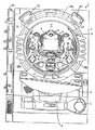
図1は、本発明に係る遊技機の一例のパチンコ遊技機1およびこれに対応して設置されたカードユニット50の正面図である。
【0025】
パチンコ遊技機1は、額縁状に形成されたガラス扉枠2を有する。ガラス扉枠2の下部表面には、打球供給皿3がある。打球供給皿3の下部には、打球供給皿3から溢れた景品玉を貯留する余剰玉受皿4と打球を発射する打球操作ハンドル(操作ノブ)5とが設けられている。ガラス扉枠2の後方には、遊技盤6が着脱可能に取付けられている。また、遊技盤6の前面には遊技領域7が設けられている。
【0026】
遊技領域7の中央付近には、画像表示領域9を有する可変表示装置8が設けられており、可変表示装置8の上部には可変表示器10が、下部には始動入賞記憶表示器18が、それぞれ設けられている。
【0027】
また、可変表示装置8の下方には始動入賞口14を構成する始動用電動役物15が、その側部には打玉を導く通過ゲート11が、それぞれ設けられている。さらに、始動入賞口14の下方には可変入賞球装置19が取付けられている。
【0028】
可変表示装置8の画像表示領域9では、「左図柄」、「中図柄」、「右図柄」の3つの特別図柄が上から下へスクロールされることによって可変表示される。このパチンコ遊技機1では、特別図柄として、左中右図柄共通で数字図柄「1」〜「9」、および、英字図柄「A」〜「C」の計12図柄が表示される。特別図柄は、打玉が始動入賞口14へ始動入賞することに基づいて可変開始される。その他、画像表示領域9には、遊技の演出効果を高めるための様々なキャラクタが表示される。
【0029】
可変表示装置8の側部の通過ゲート11に進入した打玉は、ゲートスイッチ12により検出された後、玉出口13を経て、始動入賞口14の方に導かれる。ゲートスイッチ12で打玉が検出されると、可変表示器10に停止表示されている普通図柄が可変開始する。そして、その表示結果が予め定められた特定の表示結果(たとえば7)となった場合には、ソレノイド16が励磁されることによって始動入賞口14を構成している始動用電動役物15が所定時間開成し、打玉を始動入賞口14に入賞させ易い状態となる。可変表示器10の可変表示中に打玉が通過ゲート11を通過した場合には、その通過が記憶され、可変表示器10の可変表示が終了して再度変動を開始可能な状態になってからその通過記憶に基づいて可変表示器10が可変開始する。この通過記憶の上限はたとえば「4」に定められており、現時点での通過記憶数は通過記憶表示器(図示せず)により表示される。
【0030】
始動入賞口14に入った始動入賞玉は、始動口スイッチ17によって検出される。始動口スイッチ17で打玉が検出されると、可変表示装置8の特別図柄が可変開始する。たとえば、特別図柄の可変表示中に打玉が始動口スイッチ17で検出された場合には、その始動入賞が記憶され、特別図柄の変動が終了して再度、変動を開始可能な状態になってからその始動入賞記憶に基づいて特別図柄が可変開始する。この始動入賞記憶の上限はたとえば「4」に定められており、現時点での始動入賞記憶数は始動入賞記憶表示器18により表示される。始動入賞記憶表示器18は4個の表示部(LED)を有し、始動入賞が記憶される毎に、そのLEDを1つ追加して点灯する。そして、画像表示領域9において特別図柄の可変表示が開始される毎に、LEDを1つ滅灯させる。
【0031】
可変表示装置8における左中右の各特別図柄のスクロールは、たとえば、左図柄、右図柄、中図柄の順で終了して最終的な表示結果が導出表示される。その結果、同一種類の図柄のゾロ目(たとえば、111、222等)が停止表示されると大当りとなる。大当りが発生すれば、ソレノイド21が励磁されて開閉板20が傾動して可変入賞球装置19の大入賞口が開口する。これにより、可変入賞球装置19が遊技者にとって有利な第1の状態となる。この第1の状態は、所定期間(たとえば30秒間)の経過または打玉の所定個数(たとえば10個)の入賞のうちいずれか早い方の条件が成立することにより終了し、遊技者にとって不利な第2の状態となる。大入賞口には、特定領域(Vポケット)に入った入賞玉を検出するVカウントスイッチ22と、特定領域以外の通常領域へ入賞した入賞玉を検出するカウントスイッチ23とが設けられている。第1の状態となっている可変入賞球装置19内に進入した打玉が特定領域(Vポケット)に入賞してVカウントスイッチ22により検出されれば、その回の第1の状態の終了を待って再度開閉板20が開成されて第1の状態となる。この第1の状態の繰返し継続制御は最大15回まで実行可能であり、繰返し継続制御が実行されている遊技状態を特定遊技状態(大当り状態)という。なお、繰返し継続制御において、可変入賞球装置19が第1の状態にされている状態がラウンドと呼ばれる。繰返し継続制御の実行上限回数が16回の場合には、第1ラウンドから第16ラウンドまでの16ラウンド分、可変入賞球装置19が第1の状態にされ得る。
【0032】
可変表示装置8に表示された大当りの結果が予め定められた確変図柄のゾロ目により構成されるものである場合には、通常遊技状態に比べて大当りが発生する確率が向上された確率変動状態となる。以下、確変図柄による大当りを確変大当りという。また、確変図柄以外の大当り図柄を非確変図柄といい、非確変図柄のゾロ目による大当りを非確変大当りという。たとえば、数字図柄「1」〜「9」のうちの奇数図柄と、英字図柄「B」、「D」との合計6図柄が確変図柄であり、それ以外の偶数図柄および英字図柄「A」、「C」が非確変図柄である。
【0033】
確変大当りが発生すると、少なくとも次回大当りが発生するまで確率変動状態に制御される。また、次回、確変大当りが発生すれば、確率変動状態が継続する。このパチンコ遊技機1では、確率変動状態の継続制御が無制限に行なわれることを制限するために、確率変動状態中に確変大当りが連続的に発生する回数について上限回数が設定されている。そして、この上限回数に基づいて大当りの表示態様が非確変大当りとされた場合には、その時点で確率変動状態の継続制御が強制的に終了する。なお、確変図柄での大当りを禁止する制限が行なわれることは、リミッタの作動と呼ばれる。
【0034】
さらに、このパチンコ遊技機1では、可変表示装置8における特別図柄の可変表示の結果がはずれの場合にも、その表示結果に基づいて特定遊技状態となることがある。以下の説明においては、このような特定遊技状態となる特殊なはずれを、通常のはずれと区別して“疑似はずれ”という。
【0035】
この“疑似はずれ”は、画像表示領域9の表示状態が一定の条件を満たす場合にのみ発生する。具体的には、おまけで大当りを与えることを示唆する“お助けマーク(特別キャラクタともいう)”が、はずれが連続して発生する毎に所定の確率で画像表示領域9に順次表示されていき、“お助けマーク”の数が2つになった場合には次回の特別図柄の可変表示において“疑似はずれ”が発生可能な状態となる。可変表示装置8に“お助けマーク”が2つ表示された状態で“疑似はずれ”が発生した際には、“お助けマーク”がさらに1つ追加して計3つ表示された状態となり、かつ、おまけで大当りにする旨を報知する人物キャラクタが表示される。
【0036】
このように、このパチンコ遊技機1では、はずれが連続して発生する毎に所定の確率で“お助けマーク”が画像表示領域9に順次表示されていき、その数によっては可変表示結果がはずれの場合にも特定遊技状態に制御される場合があるために、はずれが連続して発生していても極力遊技者の遊技意欲が減退してしまうことを防止可能となる。
【0037】
その他、遊技盤6には、複数の入賞口24が設けられている。また、遊技領域7の左右周辺には、遊技中に点灯表示される装飾ランプ25が設けられ、下部には、入賞しなかった打玉を回収するアウト口26がある。また、遊技領域7の外側の左右上部には、効果音を発する2つのスピーカ27が設けられている。遊技領域7の外周には、遊技効果LED28aおよび遊技効果ランプ28b,28cが設けられている。そして、この例では、一方のスピーカ27の近傍に、景品玉払出時に点灯する賞球ランプ51が設けられ、他方のスピーカ27の近傍に、補給玉が切れたときに点灯する玉切れランプ52が設けられている。
さらに、図1には、パチンコ遊技台1に隣接して設置され、プリペイドカードが挿入されることにより玉貸を可能にするカードユニット50も示されている。カードユニット50には、カード利用可表示ランプ151が設けられており、カードユニット50が使用可能な状態にある旨が、このカード利用可表示ランプ151の点灯または点滅により遊技者に知らされる。このカードユニット50は、遊技機設置島に設置されている複数台のパチンコ遊技機1の間に挿入された状態で設置されており、左右どちらの遊技機に接続されているかが連結台方向表示器153により表示される。
【0038】
遊技者がカード残高の記録されたプリペイドカードをカード挿入口155に挿入すると、そのプリペイドカードに記録されているカード残高が読取られる。次に、遊技者が所定の貸玉操作を行なうことにより、予め入力設定されている貸出単位額分の残高が減額されるとともに、その貸出単位額分の打玉がパチンコ遊技機1の打球供給皿3に貸出される。
【0039】
カードユニット50には端数表示スイッチ152が設けられている。この端数表示スイッチ152を押圧操作することにより、たとえばカード残高やエラーが発生した場合のエラーコードなどの情報がパチンコ遊技機1に設けられた情報表示器(図示省略)に表示される。図中156はカードユニット錠であり、このカードユニット錠156に所定のキーを挿入して解錠操作することにより、カードユニット50の前面側を開成できるように構成されている。
【0040】
次に、パチンコ遊技機1の背面の構造について説明する。図2は、カードユニットが隣接されたパチンコ遊技機の一部内部構造を示す全体背面図である。
【0041】
パチンコ遊技機1の遊技盤6の裏面側には、機構板36が設けられている。この機構板36の上部には玉タンク38が設けられ、パチンコ遊技機1が遊技機設置島に設置された状態でその上方からパチンコ玉が玉タンク38に供給される。玉タンク38内のパチンコ玉は、誘導樋39を通って玉払出装置に供給される。機構板36には、中継基板30を介して画像表示領域9の表示制御を行なう可変表示制御ユニット29、基板ケース32に覆われ遊技制御用マイクロコンピュータ等が搭載された遊技制御基板31、可変表示制御ユニット29と遊技制御基板31との間の信号を中継するための中継基板33、およびパチンコ玉の払出制御を行なう払出制御用マイクロコンピュータ等が搭載された賞球基板37が設置されている。さらに、機構板36には、モータの回転力を利用して打玉を遊技領域7に発射する打球発射装置34と、スピーカ27および遊技効果ランプ・LED28a,28b,28cに信号を送るためのランプ制御基板35が設けられている。
【0042】
図3は、パチンコ遊技機1の遊技盤6を背面から見た背面図である。遊技盤6の裏面には、図3に示すように、各入賞口および入賞球装置に入賞した入賞玉を所定の入賞経路に沿って導く入賞玉集合カバー40が設けられている。入賞玉集合カバー40により導かれた入賞玉は入賞玉を1個宛処理する入賞玉処理装置(図示せず)に供給される。入賞玉処理装置には入賞球検出スイッチ99(図4参照)が設けられており、入賞球検出スイッチ99の検出信号は遊技制御基板31に送られる。
【0043】
図4は、遊技制御基板31における回路構成の一例を示すブロック図である。図4には、制御基板として、遊技制御基板(主基板ともいう)31、賞球基板37、ランプ制御基板35、音声制御基板70、発射制御基板91および表示制御基板80が示されている。
【0044】
賞球基板37、ランプ制御基板35、音声制御基板70、発射制御基板91および表示制御基板80には、マイクロコンピュータ等が搭載されており、たとえば、CPUやI/Oポートが設けられている。
【0045】
賞球基板37には、玉払出装置97、および、カードユニット50が接続される。ランプ制御基板35には、遊技効果LED28a、賞球ランプ51、玉切れランプ52、および遊技効果ランプ28b,28cが接続される。発射制御基板91には、操作ノブ(打球操作ハンドル)5と打球ハンマー(図示省略)を駆動する駆動モータ94とが接続される。駆動モータ94の駆動力は、操作ノブ5の操作量に従って調整される。表示制御基板80には可変表示装置8(図示省略)が接続される。音声制御基板70にはスピーカ27が接続される。
【0046】
遊技制御基板31には、遊技制御プログラムに従ってパチンコ遊技機1を制御する基本回路(遊技制御用マイクロコンピュータ)53と、スイッチ回路58と、ソレノイド回路59と、ランプ・LED回路60と、情報出力回路64と、初期リセット回路65と、アドレスデコード回路67とが設けられている。
【0047】
基本回路53は、遊技制御用のマイクロコンピュータであり、遊技制御用のプログラム等を記憶するROM54、ワークメモリとして使用されるRAM55、制御用のプログラムに従って制御動作を行なうCPU56、I/Oポート57を含む。基本回路53は、定期的(たとえば2msec毎)にリセットされてROM54に記憶されている遊技制御プログラムを先頭から繰返し実行する。
【0048】
初期リセット回路65は、電源投入時に基本回路53をリセットする回路である。基本回路53は、初期リセット回路65から送られてきた初期リセットパルスに応答してパチンコ遊技機1を初期化する。アドレスデコード回路67は、基本回路53から与えられるアドレス信号をデコードしてI/Oポート57のうちのいずれかのポートを選択するための信号を出力する回路である。
【0049】
スイッチ回路58は、各種スイッチからの信号を基本回路53に与える回路である。スイッチ回路58には、ゲートスイッチ12、始動口スイッチ17、Vカウントスイッチ22、カウントスイッチ23、および、入賞球検出スイッチ99が接続される。
【0050】
情報出力回路64は、基本回路53から与えられるデータに従って、確率変動が生じて確率変動状態となっていることを示す確変情報、大当りが発生し特定遊技状態となっていることを示す大当り情報、および、始動入賞のうち画像表示領域9の可変表示に有効に使用される始動入賞の発生を示す始動入賞情報をホール管理コンピュータ等のホストコンピュータに対して出力する回路である。
【0051】
ソレノイド回路59は、始動用電動役物15の可動片を動作させるソレノイド16および可変入賞球装置19の開閉板20を開閉するソレノイド21を基本回路53からの指令に従って駆動する回路である。
【0052】
ランプ・LED回路60は、可変表示器(普通図柄用可変表示器)10、装飾ランプ25、および始動記憶表示器18の点灯および滅灯を制御する回路である。
【0053】
遊技制御基板31から賞球基板37、ランプ制御基板35、音声制御基板70、および表示制御基板80には、指令情報の一例となるコマンドが送信される。
【0054】
遊技制御基板31から賞球基板37に伝送されるコマンドには、賞球の払出制御に関する指令情報としてのコマンドと、貸玉の払出制御に関する指令情報としてのコマンド(たとえば、玉貸し禁止コマンド、玉貸し禁止解除コマンド等)とが含まれる。
【0055】
また、遊技制御基板31から表示制御基板80に伝送されるコマンドは表示制御コマンドであり、その表示制御コマンドのうち特別図柄に関するコマンドには、可変表示装置8の変動を開始させるための変動開始コマンドや確定図柄(予定停止図柄)を指定する確定図柄指定コマンド、変動の終了を指定する図柄確定コマンド等がある。この表示制御コマンドはそれぞれ1バイトデータからなるMODEデータとEXTデータとの2組の2バイトデータから構成されている。MODEデータは変動開始コマンドや確定図柄指定コマンド等のコマンド種別を示すデータであり、EXTデータはMODEデータにより示されたコマンド種別のうちの特定の表示制御内容を具体的に指定するデータである。
【0056】
基本回路53は、大当りあるいは入賞等の発生に基づき、所定のランプ制御コマンドをランプ制御基板35へ出力する。ランプ制御基板35では、ランプ制御コマンドに基づく上記電気的装飾部品の点灯制御が行なわれる。
【0057】
基本回路53は、大当りあるいは入賞等の発生に基づき、所定の音声制御コマンドを音声制御基板70へ出力する。音声制御基板70では、音声制御コマンドに基づいて所定の効果音をスピーカ27から出力させる制御が行なわれる。
【0058】
基本回路53は、入賞球検出スイッチ99の検出信号と始動口スイッチ17の検出信号、Vカウントスイッチ22の検出信号、カウントスイッチ23の検出信号に基づいて、所定個数の景品玉を払出すための賞球信号を賞球基板37に出力する。賞球基板37では、その出力されてきた賞球信号に基づいて玉払出装置を制御して所定個数の景品玉を払出すための制御を行なう。
【0059】
具体的には、可変入賞球装置19の大入賞口に入賞した入賞玉については1個の入賞玉につきたとえば15個の景品玉が払出され、始動入賞口14に入賞した入賞玉については1個の入賞玉につきたとえば6個の景品玉が払出され、その他の入賞口24に入賞した入賞玉については入賞玉1個につきたとえば10個の景品玉が払出されるように制御される。
【0060】
このような3種類の個数の景品玉を払出すべく、遊技制御基板31は次のように制御動作を行なう。始動口スイッチ17、Vカウントスイッチ22またはカウントスイッチ23からの検出信号が入力されると、その検出信号を賞球の払出個数決定の際に用いる払出個数決定用データとして、スイッチに応じた賞球の払出個数別に一時的に内部に記憶する。その後、入賞球検出スイッチ99からの検出信号が入力されれば、その入力以前に始動口スイッチ17からの検出信号があったかどうかを払出個数決定用データを参照することによって判断し、あった場合には遊技制御基板31は賞球基板37に対し「6」の賞球個数を払出指令するための賞球指令信号を出力する。一方、入賞球検出スイッチ99からの検出信号があった場合に、それ以前にVカウントスイッチ22またはカウントスイッチ23からの検出信号があった場合には、遊技制御基板31は「15」の賞球個数の賞球指令信号を賞球基板37に出力する。さらに、入賞球検出スイッチ99からの検出信号があった場合において、それ以前に始動口スイッチ17,Vスイッチ22,カウントスイッチ23のいずれからも検出信号が入力されていなかった場合には、遊技制御基板31は「10」の賞球個数を払出し指令するための賞球指令信号を賞球基板37に出力する。
【0061】
遊技制御基板31から賞球基板37に送られた賞球個数信号は、賞球基板37に設けられた払出制御用マイクロコンピュータ(図示省略)により受信される。払出制御用マイクロコンピュータは、玉払出装置97を駆動して賞球個数信号により特定される個数の賞球を払出す制御を行なう。
【0062】
図5は、表示制御基板80内の回路構成を、画像表示を実現するCRT82とともに示すブロック図である。RAM101aを内蔵する表示制御用CPU101は、制御データROM102に格納されたプログラムに従って動作し、遊技制御基板31から入力バッファ回路105における入力バッファ105aを介してINT信号(ストローブ信号、割込信号ともいう)が入力されると表示制御用CPU101が割込動作状態となって表示制御用のコマンドデータを取込む。そして、取込んだ表示制御コマンドデータに従って、CRT82に表示される画像の表示制御を行なう。制御データROM102には、確変の抽選演出用の表示パターンに関するデータが複数種類記憶されている。
【0063】
具体的には、表示制御用CPU101は、表示制御コマンドデータに応じた指令をVDP103に与える。VDP103は、キャラクタROM86から必要なデータを読出す。そして、VDP103は、入力したデータに従ってCRT82に表示するための画像データを生成し、その画像データをVRAM87に格納する。そして、VRAM87内の画像データは、R(赤),G(緑),B(青)信号(RGB信号)に変換され、D/A変換回路104でアナログ信号に変換されてCRT82に出力される。
【0064】
なお、図5には、VDP103をリセットするためのリセット回路83、VDP103に動作クロックを与えるための発振回路85、使用頻度の高い画像データを格納するキャラクタROM86、および表示制御コマンドデータを入力する入力バッファ回路105も示されている。キャラクタROM86に格納される使用頻度の高い画像データとは、たとえば、CRT82に表示される人物、動物、または、文字、図形もしくは記号等からなる画像などである。
【0065】
表示制御用CPU101は、後述する表示制御コマンドデータを記憶しておくためのRAM101aを内蔵しており、遊技制御基板31から表示制御コマンドを受信すると、各変動パターン(演出パターン)において予め決められている背景やキャラクタを画面上で移動表示する制御を行なう。なお、予め決められているタイミングで背景やキャラクタの切換も行なわれるが、それらも表示制御用CPU101が独自に制御する。
【0066】
また、表示制御基板80側において表示制御コマンドが入力される入力バッファ回路105は、遊技制御基板31から表示制御基板80へ向かう方向にのみ信号の伝送を許容するが表示制御基板80側から遊技制御基板31側へ向かう信号の伝送を行なわない不可逆性入力手段である。入力バッファ回路105を構成する入力バッファ105aとして、たとえば、汎用のCMOS−ICである74HC244が2チップ用いられる。この入力バッファ105aのイネーブル端子には常にローレベル(GNDレベル)が与えれている。このような構成によれば、表示制御基板80から遊技制御基板31に信号が与えられる可能性を確実になくすことができる。従って、表示制御基板80側から遊技制御基板31側に信号が伝わる余地はなく、表示制御コマンドの伝送経路に不正改造が加えられても、不正改造によって出力される信号が遊技制御基板31側に伝わることはない。このため、遊技制御基板31と表示制御基板80との間の信号の一方向通信が担保され、表示制御コマンドの伝送経路を介して遊技制御基板31に不正な信号(データ)を入力させて不正な制御動作を行なわせる不正行為を確実に防ぐことができる。また、不可逆性入力手段は、バッファIC回路で構成されているために、比較的容易に遊技制御手段への不正情報の入力を阻止できる。なお、不可逆性入力手段として、個別のトランジスタ等の他の回路素子を設けてもよい。
【0067】
また、遊技制御基板31側において表示制御コマンドが出力される出力バッファ回路63も同様に、遊技制御基板31から表示制御基板80へ向かう方向にのみ信号の伝送を許容するが表示制御基板80側から遊技制御基板31側へ向かう信号の伝送を行なわない不可逆性を有する出力インタフェースである。従って、表示制御基板80側から遊技制御基板31側に信号が伝わる余地はなく、表示制御コマンドの伝送経路に不正改造が加えられても、不正改造によって出力される信号が遊技制御基板31側に伝わることはない。
【0068】
図6は、遊技制御基板31側の基本回路53が遊技制御に用いる各種ランダムカウンタを示す図である。図6には、ランダム1、ランダム2、ランダム3(3−1,3−2,3−3)、ランダム4、および、ランダム5の7種類のランダムカウンタが示されている。
【0069】
ランダム1は、始動記憶がある場合にその始動記憶に基づく特別図柄の可変表示の結果を大当りとするか否かを決定するために用いられる大当り決定用ランダムカウンタである。このランダムカウンタは、タイマ割込毎(具体的には0.002秒毎)に1ずつ加算更新され、0から加算更新されてその上限である299まで加算更新された後再度0から加算更新される。
【0070】
ランダム3(3−1,3−2,3−3)は、ランダム1の抽出値に基づいて特別図柄の可変表示の結果をはずれとすることが決定された場合に、確定図柄(予定停止図柄)の種類を決定するために用いられるはずれ出目決定用ランダムカウンタである。
【0071】
ランダム3−1は左図柄決定用であり、0から加算されてその上限である11まで加算されると再度0から加算される。ランダム3−1は、タイマ割込毎すなわち0.002秒毎に1ずつ加算される。ランダム3−2は、中図柄決定用のランダムカウンタであり、0から加算されてその上限である11まで加算されると再度0から加算される。ランダム3−2は、ランダム3−1の桁上げ毎に1ずつ加算される。ランダム3−3は、右図柄決定用のランダムカウンタであり、0から加算されてその上限である11まで加算された後再度0から加算される。ランダム3−3は、ランダム3−2の桁上げごとに1ずつ加算される。
【0072】
ランダム4はリーチ状態を表示させる場合のリーチ種類決定用ランダムカウンタである。ランダム4は、0から加算されてその上限である121まで加算されると再度0から加算される。ランダム4は、タイマ割込毎すなわち0.002秒毎、および、割込処理余り時間毎に1ずつ加算される。
【0073】
ここで、リーチ(リーチ状態)とは、表示状態が変化可能な可変表示装置を有し、該可変表示装置が時期を異ならせて複数の表示結果を導出表示し、該複数の表示結果が予め定められた特定の表示態様の組合せとなった場合に、遊技状態が遊技者にとって有利な遊技状態(特定遊技状態)となる遊技機において、前記複数の表示結果の一部がまだ導出表示されていない段階で、既に導出表示されている表示結果が前記特定の表示態様の組合せとなる条件を満たしている表示状態をいう。
【0074】
また、別の表現をすれば、リーチ状態とは、可変表示装置の可変表示制御が進行して表示結果が導出表示される前段階にまで達した時点でも、前記特定の表示態様となる表示条件から外れていない表示態様をいう。そして、たとえば、前記特定の表示態様の組合せが揃った状態を維持しながら複数の可変表示部による可変表示を行なう状態もリーチ状態に含まれる。
【0075】
また、リーチ状態とは、可変表示装置の表示制御が進行して表示結果が導出表示される前段階にまで達した時点での表示状態であって、前記表示結果が導出表示される以前に決定されている前記複数の可変表示部の表示結果の少なくとも一部が前記特定の表示態様となる条件を満たしている場合の表示状態をいう。
【0076】
さらにリーチの中には、それが出現すると、通常のリーチに比べて、大当りが発生しやすいもの(大当りの期待度が高いもの)がある。このような特定のリーチをスーパーリーチという。
【0077】
ランダム5は、ランダム1の抽出値に基づいて特別図柄の可変表示の結果を大当りとすることが決定された場合に、確定図柄(予定停止図柄)の種類を決定するために用いられる大当り図柄決定用ランダムカウンタである。ランダム5は0から加算されてその上限である5まで加算された後再度0から加算される。ランダム5は、タイマ割込毎すなわち0.002秒毎に1ずつ加算される。
【0078】
図7〜図10は、表示制御コマンドを説明するための説明図である。表示制御コマンドは、1バイトデータからなるMODEデータと、同じく1バイトデータからなるEXTデータとの計2バイトのデータからなる。このうち、MODEデータは、表示制御データの種別を指定するデータである。一方、EXTデータはMODEデータにより示されたコマンド種別のうちの特定の表示制御内容を具体的に指定するデータである。
【0079】
図7には確定図柄指定コマンドが示されている。確定図柄指定コマンドのMODEデータは、左中右図柄別に「90H」、「91H」、「92H」である。図8には変動開始コマンドが示されている。変動開始コマンドのMODEデータは「80H」である。図9には特別画面コマンドが示されている。特別画面コマンドのMODEデータは「81H」である。図10には大当り画面指定用コマンドが示されている。大当り画面指定用コマンドのMODEデータは「82H」である。
【0080】
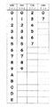
まず、図7を参照して確定図柄指定コマンドについて説明する。図7には、ランダム5およびランダム3のカウンタ値と確定図柄指定コマンドとの対応関係が示されている。前述したようにランダム5は大当り図柄を決定するために用いられるランダムカウンタであり、ランダム3ははずれ図柄を決定するために用いられるランダムカウンタである。なお、括弧書きで示す0〜11の値がランダム3のカウンタ値であり、そのカウンタ値の上に示す0〜5の値がランダム5のカウンタ値である。
【0081】
確定図柄指定コマンドは、表示制御基板80に対して確定図柄(予定停止図柄)を指定するコマンドである。この確定図柄指定コマンドにより、確定図柄が左中右図柄別に指定される。具体的には、MODEデータ「90H」により左図柄が指定され、MODEデータ「91H」により中図柄が指定され、MODEデータ「92H」により右図柄が指定される。各MODEデータに対応するEXTデータとしては、「00H」〜「0BH」の12種類用意されており、それぞれのEXTデータが特定の一の図柄を指定する。たとえば、MODEデータとEXTデータの組合せ「90H 00H」によって、左確定図柄をEXTデータ「00H」に対応する図柄とすることが指定される。表示制御基板80側には各EXTデータ「00H」〜「0BH」に対応する図柄のデータがその配列順で記憶されており、受信されたEXTデータに従う配列位置にある図柄が確定図柄として選択される。
【0082】
EXTデータ「00H」〜「0BH」によって指定される各々の図柄は、予め図示のように非確変図柄または確変図柄に定義されている。たとえば、「01H、03H、05H、07H、09H、0BH」によって指定される各々の図柄が確変図柄であり、「00H、02H、04H、06H、08H、0AH」によって指定される各々の図柄が非確変図柄である。
【0083】
遊技制御基板31側のROM54のデータ領域には、確変図柄を指定するEXTデータ「01H、03H、05H、07H、09H、0BH」のみから構成された確変図柄選択用テーブルと、非確変図柄を指定するEXTデータ「00H、02H、04H、06H、08H、0AH」のみから構成された非確変図柄選択用テーブルとが記憶されている。
【0084】
たとえば、遊技制御基板31側で非確変大当りとすることが事前決定された場合には、非確変図柄選択用テーブルによってランダム5の値が判定され、非確変図柄を指定するEXTデータが選択される。これにより、実質的には複数種類の非確変図柄の中から一の非確変図柄が指定される。一方、遊技制御基板31側で確変大当りとすることが事前決定された場合には、確変図柄選択用テーブルによってランダム5の値が判定され、確変図柄を指定するEXTデータが選択される。これにより、実質的には複数種類の確変図柄の中から一の確変図柄が指定される。また、遊技制御基板31側ではずれとすることが事前決定された場合には、ランダム3(3−1,3−2,3−3)の値が判定され、はずれ図柄を指定するEXTデータが左中右図柄別に選択される。
【0085】
以上、説明したように、ランダム3またはランダム5のカウンタ値によって確定図柄の種類が定められ、より正確には確定図柄を指定する表示制御コマンドの種類が定められる。すなわち、遊技制御基板31側では特別図柄の形態を何ら指定するものではなく、単に確変/非確変の種別と図柄の配列位置とを指定するだけである。表示制御基板80側では遊技制御基板31から出力された確定図柄指定コマンドに対応する特別図柄を選択してそれを確定図柄として設定する。ただし、後述するように可変表示結果を疑似はずれとする場合には、確定図柄指定コマンドによって指定される図柄以外の図柄が確定図柄として選択される。
【0086】
次に、図8を参照して、変動開始コマンドとしては、EXTデータ「00H」〜「06H」によって表示内容を指定する7種類のコマンドが用意されている。各変動開始コマンドにより、図示するように表示時間(可変表示期間)が指定される。表示時間はT1〜T7の順で長くなる。表示制御基板80側には、これらのコマンドによって指定される表示時間に対応した変動パターン(演出パターン)のデータが記憶されている。すなわち、遊技制御基板31側は、表示制御基板80に対して変動開始コマンドによって、表示時間を指定することによって、その表示時間に対応するリーチの種類や演出方法等の演出パターンを間接的に指定するが、その具体的な内容については表示制御基板80側に委ねている。これらの変動パターン(演出パターン)に対応するリーチ状態の表示内容等の演出表示のための制御プログラムや画像データは、表示制御基板80側のROM102、VDP103、キャラクタROM86に格納されており、表示制御用CPU101は、その制御プログラムに従って各種変動パターン(演出パターン)に対応する演出表示を行なう。
【0087】
なお、特定の表示時間(可変表示期間)を変動開始コマンドにより指定する場合、図示するEXTデータによって指定することに代え、表示時間そのものをコマンドとして指定するようにしてもよい。たとえば、可変表示期間が10秒の場合には、その時間を指定する「0AH」をEXTデータとすることが考えられる。
【0088】
次に、図9を参照して、特別画面コマンドデータとしては、EXTデータ「00H」〜「03H」によってその表示制御内容を指定する4種類のコマンドが用意されている。EXTデータ「00H」により指定される電源投入時画面とは、パチンコ遊技機の電源を投入した際に画像表示領域9に表示する画面を指定するデータである。これにより、パチンコ遊技機の電源を投入した際には、左図柄が4、中図柄が4、右図柄が5の画面が表示される。EXTデータ「01H」により指定される客待ち待機画面1、およびEXTデータ「02H」により指定される客待ち待機画面2は、始動記憶がないと判断される場合に、交互に表示されるデモ画面である。たとえば、客待ち待機画面1は遊技機の名称等を表示する画面であり、客待ち待機画面2は前回の始動入賞に基づく出目(可変表示装置8の表示結果)を示す画面である。EXTデータ「03H」により指定されるエラー画面は、パチンコ遊技機でエラーが発生した場合に画像表示領域9に表示する画面を指定するデータである。
【0089】
次に、図10を参照して、大当り画面指定用コマンドデータとしては、EXTデータ「00H」〜「30H」によってその表示制御内容を指定する複数種類のコマンドが用意されている。たとえば、EXTデータ「00H」によって大当り開始画面を表示することが指定され、EXTデータ「10H」によって大当りの1ラウンド目の画面を表示することが指定される。大当りが発生した際には、これらのコマンドのうち上位のコマンドから順に表示制御基板80に対して出力される。
【0090】
次に、基本回路53により実行される処理の一部をフローチャートを参照して説明する。
【0091】
図11は、基本回路53により実行される遊技制御メイン処理および割り込み処理を示すフローチャートである。図11においては、(a)に遊技制御メイン処理が示され、(b)に割り込み処理が示されている。
【0092】
図11の(a)を参照して、遊技制御メイン処理においては、まず、スタックポインタの指定アドレスをセットするためのスタックセット処理が行なわれる(S1)。次いで、初期化処理が行なわれる(S2)。初期化処理では、RAM55にエラーが含まれているか判定され、エラーが含まれている場合には、RAM55を初期化することおよび各種フラグの初期設定などの処理が行なわれる。さらに、初期化処理では、後述する割り込み処理を実行するタイミングを規定するタイマ割り込み時間(たとえば0.002秒)をCPU56に設定する処理がなされる。これにより、電源投入等によるリセット後の最初の割り込み処理の実行タイミング規定のための計時が開始される。
【0093】
次に、停止図柄を決定する等のための表示用乱数更新処理が行なわれる(S3)。このパチンコ遊技機1においては、可変表示装置8の可変表示での特別図柄の停止図柄が乱数(ランダムカウンタのカウンタ値)に基づいて決定される。このS3では、そのように停止図柄を決定するための表示用乱数が更新される。表示用乱数更新処理は、無限ループにより繰返し実行され続けるが、後述する割り込み処理が起動された場合には、表示用乱数更新処理を構成するプログラムのうちの実行中の位置で一時停止され、その割り込み処理が終了すると一時停止したプログラムの位置から実行が再開される。
【0094】
次に、図11の(b)を参照して、割り込み処理は、CPU56により管理されるタイマ割り込み用のタイマの計時値が設定値(S2またはS13で設定されるタイマ割り込み時間)になるごとに実行が開始される。
【0095】
割り込み処理においては、まず、ランプ制御基板35および音声制御基板70に音声発生やLED点灯制御用の所定のコマンドを送信するための処理が行なわれるとともに、情報出力回路64を介してホール管理用コンピュータに大当り情報、始動情報、確率変動情報などのデータを送信するためのデータ出力処理が行なわれる(S4)。次に、パチンコ遊技機1の内部に備えられている自己診断機能によって種々の異常診断をし、その結果に応じて必要ならば警報を発生させるためのエラー処理が行なわれる(S5)。次に、遊技制御に用いられる各種の判定用乱数を示す各ランダムカウンタを更新する判定用乱数更新処理が行なわれる(S6)。
【0096】
次に、特別図柄プロセス処理が行なわれる(S7)。特別図柄プロセス処理では、複数種類の処理のうちの1つが特別図柄プロセスフラグの値に従って選択されて実行される。そして、特別図柄プロセスフラグの値は、遊技状態に応じて各処理中において更新される。次に、普通図柄プロセス処理が行なわれる(S8)。普通図柄プロセス処理では、7セグメントLEDによる普通図柄用可変表示器10を所定の順序で制御するための普通図柄プロセスフラグに従って該当する処理が選び出されて実行される。そして、普通図柄プロセスフラグの値は、遊技状態に応じて各処理中に更新される。
【0097】
次に、ゲートスイッチ12、始動口スイッチ17、Vカウントスイッチ22、カウントスイッチ23等の状態を入力し、各入賞口や可変入賞球装置に対する入賞があったか否か等を判定するスイッチ処理が行なわれる(S9)。始動口スイッチ17により始動入賞が検出された場合には、このスイッチ処理において、始動記憶処理が実行される。具体的には、始動口スイッチ17により始動入賞が検出されると、そのタイミングで大当り判定用のランダムカウンタのカウンタ値が抽出され、始動記憶用の特別図柄判定用バンクにその抽出値が記憶される。これにより始動記憶がなされる。始動記憶用の特別図柄判定用バンクは、バンク0〜バンク3の4つ構成されており、この4つのバンクによって最大4つの始動記憶を可能にしている。よって、始動入賞が検出された際にすべてのバンクに記憶がある場合には、その始動入賞が無効とされる。
【0098】
次に、S3と同様の表示用乱数更新処理が行なわれる(S10)。次に、賞球基板37との間の入賞球信号処理が行なわれる(S11)。すなわち、基本回路53は、賞球基板37より賞球数要求信号が入力されると、賞球基板37に対して出力すべき賞球コマンド(賞球数指定信号)を選択する。次に、選択した賞球コマンドを出力するための賞球コマンド出力処理が行なわれる(S12)。賞球基板37は、この賞球数指定信号に基づいて玉払出装置97を駆動制御する。
【0099】
次に、タイマ割り込み時間設定処理が行なわれる(S13)。S13においては、前述したようなタイマ割り込み時間(たとえば0.002秒)をS2の場合と同様に設定する処理が実行される。S13の後、この割り込み処理が終了する。これにより、この割り込み処理の終了時にS13によってタイマ割り込み時間が設定され、次の割り込み処理の実行タイミングを規定するための計時が開始されることとなる。したがって、割り込み処理が終了するごとにタイマ割り込みのための時間が計時され、その後タイマ割り込み時間が経過するごとに割り込み処理が実行されることとなる。この割り込み処理が終了すると、前述したメイン処理のプログラムの実行が、一時停止していた位置から再開される。
【0100】
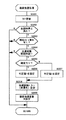
次に、図12を参照して、図11のS7に示した特別図柄プロセス処理の概要を説明する。特別図柄プロセス処理においては、まず、前回の特別図柄の可変表示が終了して改めて特別図柄の可変表示を開始できる状態になると(スタートSW ON)、始動入賞が発生した際に抽出した大当り判定用のランダム値(ランダム1)が読出され、大当り判定値であるか否かが判定される(S20)。ランダム1の抽出値が、たとえば大当り判定値「7」である場合には可変表示結果を大当りとすることが事前決定され、それ以外の値である場合にははずれとすることが事前決定される。なお、後述する確変フラグが設定されており、遊技状態が確率変動状態にある場合には、大当り判定値が「7,11,79」となり、大当り確率が向上される。
【0101】
可変表示結果をはずれとすることが決定された場合(S20でNO)には、はずれ出目決定用ランダム値(ランダム3−1,3−2,3−3)に基づいて左中右のはずれ図柄が設定される(S26)。より正確には、表示制御基板80に対して出力すべき確定図柄指定コマンドの種類が決定される。その後、後述するS28へ移行する。
【0102】
S20で大当りとすることが決定された場合には、大当りフラグが設定される(S21)。次に、リミッタが作動しているか否かが判断される(S22)。前述したように、このパチンコ遊技機1では、確変が連続して継続した回数が所定の制限値に達しているとリミッタが作動(リミッタフラグON)する。リミッタが作動していないと判断された場合には、確変判定用のランダム2の抽出値に基づいて高確率当り(確変大当り)とするか否かが決定される(S23)。高確率当り(確変大当り)とすることが決定された場合には、確変図柄の中から大当り図柄が決定される(S24)。より正確には、図7を用いて説明した確変図柄選択用テーブルを用いてランダム5の抽出値が判定され、確変図柄を指定するための確定図柄指定コマンドの種類が決定される。次に、確変当りフラグがセットされる(S27)。確変当りフラグは、確変大当りとすることが決定されていることを示すフラグである。
【0103】
S23において確変大当りとしないことが決定された場合、もしくはS22においてリミッタが作動していると判断された場合には、非確変図柄の中から大当り図柄が選択される(S25)。より正確には、図7を用いて説明した非確変図柄選択用テーブルを用いてランダム5の抽出値が判定され、非確変図柄を指定する確定図柄指定コマンドの種類が決定される。
【0104】
S25〜S27のいずれかで確定図柄指定コマンドの種類が決定された後、変動開始コマンドが送出される(S28)。この変動開始コマンドが表示制御基板80側で受信されることにより、可変表示装置8では特別図柄の可変表示が開始される。続いて、S25〜S27で設定された確定図柄指定コマンドが送出される(S29)。表示制御基板80側では、この確定図柄指定コマンドに基づいて特別図柄の可変表示結果が判定される。
【0105】
次に、変動開始コマンドにより指定される可変表示期間が終了した後(S31)、大当りフラグがセットされているか否かが判断される(S32)。大当りフラグがセットされていない場合には、可変表示装置8の表示結果がはずれとなっているために、スタート待ち(始動待ち)の状態となる(S33)。一方、大当りフラグがセットされていると判断された場合には、確変フラグがクリアされ(S34)、続いて大当りコマンドが表示制御基板80へ送出される(S35)。大当りコマンドは、図10に示した大当り開始画面用のコマンド「82H 00H」である。表示制御基板80側ではこの大当りコマンドを受信することによって大当りの表示結果が示されている画面を大当り開始画面に切換える制御が行なわれる。次に、大当り制御が終了した後(S36)、確定図柄は確変図柄であったか否かが判断され(S37)、確変図柄であった場合には確変フラグがセットされる(S38)。これにより、確率変動状態に制御される。一方、確定図柄が確変図柄ではなかった場合には、確変フラグがセットされることなく、スタート待ち(始動待ち)の状態となる(S39)。
【0106】
図13は、表示制御コマンドの出力タイミングと左中右図柄の変動との関係を説明するためのタイミングチャートである。特別図柄の変動を開始させる際には、最初に、MODEデータ「80H」により指定される変動開始コマンド「80H ××H」が遊技制御基板31から表示制御基板80に対して出力される。なお、「80H ××H」は、図8に示した「80H 00H」〜「80H 0AH」のうちのいずれかのコマンドである。この変動開始コマンドが表示制御基板80に受信されたタイミングで、特別図柄の一斉変動が開始される。なお、前述したように変動開始コマンドの種類によりリーチの有無および可変表示期間が指定されている。表示制御基板80はその指令に基づいてリーチの演出内容や大当り予告演出の有無等を決定する。
【0107】
その後、変動開始コマンドに続いて、左中右図柄に対応する3つの確定図柄指定コマンドが順に出力される。図には、左図柄用の確定図柄指定コマンド1「90H ××H」、中図柄用の確定図柄指定コマンド2「91H ××H」、および右図柄用の確定図柄指定コマンド3「92H ××H」がその順で出力されることが示されている。なお、「××H」は、図7に示した「00H」〜「0BH」のうちのいずれかである。表示制御基板80側ではこの確定図柄指定コマンド基づいて最終的に表示結果として導出表示する確定図柄の種類が決定される。
【0108】
各図柄の変動パターン(演出パターン)としては、たとえば、加速変動から高速変動を経て低速変動に至り、揺れ変動を経て確定図柄を停止表示させるパターンが示されている。図示するタイミングチャートでは左図柄が最初に低速変動から揺れ変動に切換えられ、続いて右図柄、中図柄の順で低速変動から揺れ変動に切換えられている。
【0109】
図柄の一斉変動が開始されてから、変動開始コマンドにより指定される変動時間Tnが経過した時点で、図柄確定コマンドが遊技制御基板31から出力される。これにより、図柄の揺れ変動が終了し、確定図柄が停止表示される。
【0110】
以上、図13を用いて説明したように、遊技制御基板31側から表示制御基板80に対しては、特別図柄の変動に関し、「変動開始時期」、「確定図柄」、「図柄確定時期」の3種類の情報のみが出力される。表示制御基板80は、これら3種類の情報に従い、リーチ演出の内容などを独自に決定し、表示制御を行なう。このように、表示制御については、遊技制御基板31とは別体の表示制御基板80側で行なわれるため、遊技制御基板31側の表示制御の負担が軽減される。
【0111】
また、可変表示装置8を可変開始させるタイミングで変動開始コマンドが出力され、表示結果を導出表示させるタイミングで図柄確定コマンドが出力されるために、それらのコマンドによって、表示制御基板80側の表示制御用CPU101は、可変開始時期と表示結果を導出表示させる時期とを特定できる。さらに、変動開始コマンドには可変表示期間(図8に示した表示時間)やリーチの有無等の変動パターン(演出パターン)を特定可能なデータが含まれており、そのコマンドによって表示制御用CPU101は可変開始時期に加えて、変動パターン(演出パターン)をも特定できる。
【0112】
図14は、表示制御コマンドデータの出力タイミングと表示制御基板80側の表示制御コマンドのデータ取込タイミングとを説明するためのタイミングチャートである。前述したように、遊技制御手段(基本回路53)側のタイマ割込時間は2msとされている。このタイマ割込時間2msの期間において表示制御コマンドが出力される。
【0113】
まず、基本回路53はタイマ割込に伴って1バイト(D0〜D7)のMODEデータの出力を開始し、INT信号を無効状態から有効状態に切換える。表示制御基板80側では、INT信号が無効状態から有効状態に切換えられたタイミングでMODEデータの取込が行なわれる。その後、所定時間が経過すればINT信号が有効状態から無効状態に切換えられる。続いて、1バイト(D0〜D7)のEXTデータの出力が開始され、INT信号が所定の待機時間だけ無効状態となった後、有効状態に切換えられる。表示制御基板80側では、この有効状態に切換えられたタイミングにおいてEXTデータの取込が行なわれる。
【0114】
このように、遊技制御基板31の基本回路53は、表示制御基板80に対して連続的に同一の表示制御コマンドデータを繰返して出力するのではなく、所定の待機時間を設けるなどして表示制御基板80側のデータの受信性能を考慮し、表示制御コマンドデータを表示制御基板80側が認識可能な態様で1回のみ出力する。これにより、基本回路53が表示制御基板80に表示制御コマンドデータを出力する際の処理負担を軽減できる。
【0115】
図15は、表示制御用CPU101が表示制御に用いるランダムカウンタを説明するための図である。表示制御用CPU101は、表示制御にランダムD1とD2の2種類のランダムカウンタを使用する。ランダムD1は、遊技制御基板31側より大当りとすることを指定するコマンド(左中右確定図柄を指定する3つの確定図柄指定コマンドのEXTデータがすべて同一)が受信されている場合に、それに対応する大当りの表示結果を擬似はずれとするか否かを決定するために用いられるランダムカウンタである。このランダムカウンタは後述する表示用乱数更新処理2において0〜6の範囲で1ずつ繰返し更新される。
【0116】
ランダムD2は、特別キャラクタ(お助けマーク)を表示するか否かを判定するために用いられるランダムカウンタである。このランダムカウンタは、後述する表示用乱数更新処理1において0〜293の範囲で1ずつ繰返し更新される。
【0117】
図16は、図柄テーブルを説明するための図である。この図柄テーブルのデータは、制御データROM102内に記憶されている。図柄テーブルとしては、通常時図柄テーブルと擬似はずれ決定時図柄テーブルの2種類がある。擬似はずれ決定時図柄テーブルは、擬似はずれの表示結果を導出表示することが決定された場合に用いられる図柄テーブルであり、通常時図柄テーブルはそれ以外の場合に用いられる図柄テーブルである。両図柄テーブルには特別図柄の種類を指定する図柄データが格納されており、各図柄データは遊技制御基板31側から出力される確定図柄指定コマンド(図7参照)のコマンド値と対応づけられて配列されている。
【0118】
まず、通常時図柄テーブルについて説明する。通常時図柄テーブルは左中右図柄共に共通の図柄テーブルである。たとえば、左図柄の確定図柄指定コマンドとして「00H」を受信すると、表示制御用CPU101は左の確定図柄の種類を「0」に設定する。同様に、右図柄の確定図柄指定コマンドとして「01H」を受信すると、右側の確定図柄として「1」を設定する。また、大当りとすることが決定された際には左中右共に同一の図柄を指定するコマンドが遊技制御基板31から出力されるため、表示制御用CPU101はそれに応じて左中右の確定図柄を同一種類の図柄に設定する。
【0119】
次に、擬似はずれ決定時図柄テーブルについて説明する。擬似はずれ決定時図柄テーブルは、大当りとすることが決定されている場合、すなわち、遊技制御基板31側から出力された3種類の確定図柄指定コマンドのすべてが同一種類の図柄を指定している場合であって、かつ、擬似はずれとすることが表示制御基板80側で決定された場合に用いられる。この擬似はずれ決定時図柄テーブルが用いられることにより、たとえば、左中右図柄に対応する確定図柄指定コマンドのすべてが「05H」である場合には、通常時図柄テーブルによれば5のぞろめが選択されるべきところ、左図柄「5」、中図柄「A」、右図柄「5」が選択される。この場合には、左図柄と右図柄とが同一であるために、リーチ状態が表示された後、「5A5」によるはずれ(疑似はずれ)の表示結果となる。
【0120】
図17は、表示制御基板80の表示制御用CPU101が実行する表示制御メイン処理を説明するためのフローチャートである。表示制御メイン処理においては、まず、RAM101a、I/O、VDPなどをイニシャライズする処理が実行される(S100)。続いて、INT割込処理が実行される(S200)。INT割込処理では、遊技制御基板31から出力された表示制御コマンドデータを表示制御コマンド格納エリアに格納する処理が行なわれる。詳細については説明を省略する。
【0121】
次に、表示用乱数更新処理1が実行される(S300)。表示用乱数更新処理1が実行されることにより、図15に示したランダムD2の値が更新される。次に、前記S200に処理が移行し、S200およびS300の処理が繰返し実行される。
【0122】
図18は、タイマ割込処理を説明するためのフローチャートである。タイマ割込は、たとえば2msごとに発生する。この2msごとに発生するタイマ割込の際にタイマ割込処理が実行される。タイマ割込処理においては、まず、表示制御プロセス処理が実行される(S400)。表示制御プロセス処理は、表示制御プロセスフラグの値に応じ、画像表示領域9に各種表示を行なう処理である。詳細については、図19を用いて後述する。次に、表示用乱数更新処理2が実行され(S500)、図15に示したランダムD1の値が更新される。
【0123】
図19は、表示制御プロセス処理を説明するためのフローチャートである。この表示制御プロセス処理においては、コマンド処理(S401)が実行された後、表示制御プロセスフラグが示す値に応じてS402〜S406の各処理が実行される。図19には、表示制御プロセスフラグ値が各ステップS402〜S406の左肩にPF1〜PF5として示されている。
【0124】
コマンド処理(S401)は、受信された表示制御コマンドの種類を判断し、表示制御プロセスフラグの値をその表示制御コマンドの種類に応じた値に更新する処理である。詳細については説明を省略する。変動表示処理(S402)は、特別図柄の他、特別キャラクタ(お助けマーク)その他の画像表示領域9に表示されるキャラクタを制御する処理である。詳細については、図20を用いて後述する。
【0125】
また、図柄確定処理(S403)は、特別図柄の変動を終了させて確定図柄を停止させる処理であり、大当り表示処理(S404)は、大当り状態中の表示制御を行なう処理であり、表示画面処理(S405)は、デモンストレーション画面を表示させる処理であり、エラー表示処理(S406)は、遊技機がエラー状態となった場合にその旨を表示する処理である。これらのS403〜S406の詳細な説明は省略する。
【0126】
図20は、変動表示処理を説明するためのフローチャートである。変動表示処理においては、図柄変動中処理が実行された後(S1000)、プロセスフラグ(PF1)が更新されて変動停止処理が実行される(S1100)。
【0127】
図21は、図柄変動中処理を説明するためのフローチャートである。図柄変動中処理においては、まず、特別図柄を変動中の状態とするための設定がなされる(S1100)。これにより、左中右の特別図柄が停止している場合には、それらの特別図柄が一斉に変動し始める。また、一斉変動した後においてはその変動が継続される。
【0128】
次に、確定図柄指定コマンドが入力されたか否かが判断される(S1101)。確定図柄指定コマンドが入力されていない場合には、処理が終了する。確定図柄指定コマンドが入力されている場合には、そのコマンドに基づいて可変表示結果を大当り態様(ゾロ目)とすることが指定されているか否かが判断される(S1102)。具体的には、左中右の各図柄に対応する確定図柄指定コマンドのEXTデータが3つとも同一であるか否かが判断される。大当りとすることが指定されていない場合、すなわち、はずれとすることが指定されている場合には、通常時図柄テーブルが設定される(S1107)。通常時図柄テーブルは図16に示した左中右の図柄で共通のテーブルである。
【0129】
一方、大当りとすることが指定されている場合には、特別キャラカウンタの値が参照され、カウンタ値が2以上の値となっているか否かが判断される(S1103)。ここで、特別キャラカウンタは、画像表示領域9に表示されている特別キャラクタ(お助けマーク)の数を特定するためのカウンタである。特別キャラカウンタがまだ2以上の値になっていない場合には、前述したS1107に移行する。この場合には、確定図柄指定コマンドに基づいた大当り図柄が確定図柄として選択され、ぞろめによる大当りの表示結果が導出表示されることになる。つまり、特別キャラクタ(お助けマーク)が2つたまっていない段階では疑似はずれが発生しないのである。
【0130】
これに対して、特別キャラカウンタの値が2以上の値となっていると判断された場合には、ランダムD1の値が抽出され(S1104)、続いてその抽出値が予め定められた判定値と一致するか否かが判断される(S1105)。判定値と一致しないと判断された場合には、前述したS1107に移行する。この場合には、確定図柄指定コマンドに基づいた大当り図柄が確定図柄として選択され、ぞろめによる大当りの表示結果が導出表示されることになる。つまり、特別キャラクタ(お助けマーク)が2つたまっていても常に疑似はずれが発生する訳ではない。なお、ランダムD1の判定値としては、ランダムD1のカウンタ値0〜6のうちのいずれの値としてもよく、複数の値を判定値としてもよい。ランダムD1の抽出値が判定値と一致すると判断された場合には、擬似はずれ決定時図柄テーブルが設定される(S1106)。擬似はずれ決定時図柄テーブルは、左中右の図柄の組合せが予め定められた図16に示したテーブルである。この場合、特別キャラ表示パターンおよび擬似はずれ決定時演出表示パターンが設定される(S1108)。特別キャラ表示パターンが設定されることにより、疑似はずれの表示結果が導出表示されたタイミングで3つ目の特別キャラクタ(お助けマーク)が表示される。また、擬似はずれ決定時演出表示パターンが設定されることにより、擬似はずれの表示結果が導出表示されたタイミングで表示結果がはずれであるにもかかわらず大当り制御が実行される旨を報知する報知キャラクタが表示される。
【0131】
次に、特別キャラカウンタのカウンタ値がクリアされる(S1109)。次に、可変表示装置の表示結果として導出表示させる確定時図柄(確定図柄)の種類が設定される(S1110)。この際、S1106において擬似はずれ決定時図柄テーブルが設定されている場合には、擬似はずれの表示結果が設定され、S1107において通常時図柄テーブルが設定されている場合には、大当り図柄のぞろめまたははずれの表示結果が設定される。これにより、図柄変動中処理が終了する。
【0132】
図22は、変動停止処理を説明するためのフローチャートである。変動停止時処理においては、まず、可変表示期間を計時するためのタイマが更新される(S1201)。次に、左中右のすべての図柄が停止したか否かが判断される(S1202)。図柄変動中の場合には処理が終了する。全図柄が停止済みである場合には、その表示結果が大当り制御に移行する大当り態様であるか否かが判断される(S1203)。ここで、“大当り態様”には、疑似はずれは含まれない。
【0133】
S1203において大当り態様であると判断された場合には特別キャラカウンタのカウンタ値がクリアされ(S1210)、続いて特別キャラクタ(お助けマーク)の表示がすべて消去される(S1211)。特別キャラクタ(お助けマーク)は、はずればかりが連続して発生する場合に遊技者の遊技意欲が減退しないようにとの配慮から表示されるのであり、それゆえに可変表示装置8の表示結果が大当り態様となった時点で特別キャラクタ(お助けマーク)を消去するのである。なお、これに代えて、特別キャラクタ(お助けマーク)を消去しないように構成してもよく、あるいは、大当り態様が複数回発生した後に特別キャラクタ(お助けマーク)を消去するように構成してもよい。
【0134】
一方、S1203においてNOの判断がなされた場合には、特別キャラクタ表示用のランダムD2が抽出され(S1204)、続いて抽出値が予め定められた判定値と一致するか否かが判断される(S1205)。すなわち、可変表示装置8の表示結果がはずれであっても常に特別キャラクタ(お助けマーク)が1つ追加して表示される訳ではなく、一定の確率で表示される。しかしながら、これに代えて、可変表示装置8の表示結果がはずれである場合には、ランダムD2を判定することなく常に次のS1206に移行するように構成してもよい。なお、ランダムD2の判定値としては、ランダムD2のカウンタ値0〜293のうちのいずれの値としてもよく、複数の値を判定値としてもよい。
【0135】
S1205において判定値と一致しない場合には後述するS1209に移行するが、判定値と一致すると判断された場合には現時点での特別キャラカウンタのカウンタ値が1以下であるか否かが判断される(S1206)。たとえば、特別キャラカウンタのカウンタ値が現時点で2となっている場合には後述するS1209に移行するが、特別キャラカウンタのカウンタ値が1または0であると判断された場合には、特別キャラクタ(お助けマーク)を追加して1つ表示するための設定がなされる(S1207)。すなわち、画像表示領域9にすでに2つ特別キャラクタ(お助けマーク)が表示されている場合には、ランダムD2の抽出値が判定値と一致しても特別キャラクタ(お助けマーク)をさらに追加して3つにすることはしない。これは、前記S1108を用いて説明したように、特別キャラクタ(お助けマーク)が3つになった時点で疑似はずれの表示結果が導出表示されるようにするためである。
【0136】
S1207の処理の後、特別キャラカウンタのカウンタ値が1だけ加算更新される(S1208)。次に、表示コマンド(表示制御コマンド)入力待ちの状態にするための設定がなされ(S1209)、処理が終了する。
【0137】
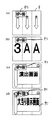
図23は、可変表示装置8の画面図である。この図23には、遊技の進行状況に伴って特別キャラクタ(お助けマーク)93が順次追加して表示された後、擬似はずれの表示結果が導出表示されるまでの過程が時系列で示されている。
【0138】
まず、図23(a)には、特別キャラクタ93が2つ表示された状態が示されている。この特別キャラクタ93は、前述したように可変表示装置8の表示結果がはずれとなる毎に所定確率で1つずつ追加して表示される。このように、可変表示装置8の表示結果がはずれとなることに基づいて特別キャラクタ93が1つずつ追加して表示されるために、はずれの結果が連続しても、遊技者の大当りに対する期待感が極力失われないようにすることができる。
【0139】
なお、特別キャラクタ93が2つ表示されると、3つ目の特別キャラクタは表示結果が擬似はずれとなった場合にのみ表示される。換言すれば、特別キャラクタ93が3つ揃うと擬似はずれの表示結果による大当りとなる。
【0140】
次に、図23(b)には、特別キャラクタ93が2つ表示された段階で特別図柄が変動している状態が示されている。この時点では、特別キャラクタ93が2つ表示されているために、表示結果がはずれとなってもおまけで大当り制御がなされるかもしれないという期待感を遊技者に抱かせることができる。但し、制御の上では、大当り確率に変化はない。このため、一定の大当り確率を担保しながらも、遊技者の大当りに対する期待感を向上させることができる。
【0141】
次に、図23(c)には、図23(b)に示された特別図柄の可変表示が行なわれた後、疑似はずれの表示結果が導出表示された状態が示されている。表示結果が擬似はずれである場合には、確定図柄が停止した後、3つ目の特別キャラクタ93が表示される。その後、図23(d)に示すように、表示結果が擬似はずれであることを報知する報知キャラクタ92が出現し、予め定められた擬似はずれ決定時演出表示パターンによる演出が行なわれる。この報知キャラクタ92の報知によって、遊技者は疑似はずれであることを容易に把握できる。
【0142】
以上、説明したように、遊技をある程度の期間行なっているにも拘らず可変表示装置の表示結果がはずれになることが繰り返されると、特別キャラクタ(お助けマーク)93の数が追加して表示されていくので、長期に亘って大当りが1回も導出表示されなかった場合であっても、遊技者の大当りに対する期待感が失われてしまうことを極力防止できる。これは、特別キャラクタ(お助けマーク)93が3つたまると、特別図柄の表示結果がはずれとなっても、常に大当り制御がなされるという期待感を遊技者が抱くためである。このため、遊技者は、特別キャラクタ(お助けマーク)93がたまることにある程度の魅力を感じ、大当りが発生しない状態が継続しても、遊技を止めづらくなり、遊技機の稼働率を上げることができる。また、遊技場においては、前日の特別キャラクタ(お助けマーク)93の表示状態を維持した状態で開店することによって、サービス台を装うこともできる。
【0143】
第2実施の形態
次に、図24を用いて第2実施の形態を説明する。第2実施の形態は、第1実施の形態における擬似はずれの表示画面に関する変形例である。この例では、画面の左上部に特別キャラクタ93の一例となるHP(ヒットポイント)が常時表示され、そのヒットポイントが100になると擬似はずれとなる。このヒットポイントは、可変表示装置8に表示されるサブゲームの結果によって加減算される。サブゲームは、可変表示装置8の表示結果が導出表示された後に画像表示領域9に表示される。このサブゲームは、レースゲームやアドベンチャーゲーム等であって、そのゲーム結果はヒットポイントが99となるまでは図22のS1205によって決定され、ヒットポイントが99となった後は図21のS1105によって決定される。
【0144】
図24(a)〜図24(d)には、ヒットポイントが99の状態で特別図柄の可変表示が開始された後、サブゲームの結果によって疑似はずれとなる場合が時系列で示されている。その流れを説明すると、まず、特別図柄の可変表示が開始された後(図24(a))、はずれの表示結果が導出表示され(図24(b))、続いて画面がサブゲーム用の演出画面に切り替わる(図24(c))。その後、サブゲームの結果が入賞となり、ヒットポイントが100になるとともにはずれの表示結果ではあるが大当りが発生することを示す報知用キャラクタの一例となる画面95が表示される(図24(d))。
【0145】
第3実施の形態
次に、図25〜図31を用いて第3実施の形態を説明する。
【0146】
まず、最初に図31を参照して、可変表示装置8の画像表示領域9に表示される内容について説明する。第3実施の形態では、はずれの表示結果が繰り返される毎に、特別キャラクタの一例となるチャンスメータ93のメータ値が「CHANCE」と表示された方向に除々に増加される。そして、図31(a)に示すように、あと1目盛りでチャンスメータ93のメータ値が最大値になる状態となれば、疑似はずれが発生し得る状態となる。図31(a)のような表示状態を“疑似はずれのリーチ状態”という。なお、ここでは、図示を省略しているが、リーチ状態であることがわかるようにチャンスメータ93が点滅するなどの特有のリーチ状態の演出がなされる。
【0147】
たとえば、図31(a)の後の特別図柄の表示結果が疑似はずれとなる場合には、図31(b)に示すようにチャンスメータ93が最大値を示し、かつ、報知キャラクタ92が出現する。これによって遊技者に疑似はずれであることが報知される。
【0148】
次に、図31(c)に示すように画面が切替わって確変であるか非確変であるかを示す抽選画面が表示される。この時、特別図柄が一斉変動するとともに、背景色が青黄赤のうちのいずれかの色に変化する。背景色は、抽選画面の表示結果が確変となることを期待できる期待度を表わすものであり、たとえば、青、黄、赤の順で期待度が高いことを示す。
【0149】
次に、図31(d)に示すように抽選画面の結果が表示される。図では、確変図柄のゾロ目が表示されており、確変大当りである場合が例示されている。なお、遊技者にそのことが容易に識別できるように「確変大当り」という文字情報によってもその旨が報知されている。なお、ここでは、抽選画面において左中右の3つの図柄を変動させるようにしたが、確変/非確変の抽選であるために、1つの図柄を変動させるように構成してもよい。また、確変/非確変の抽選専用の図柄を変動させるように構成してもよい。
【0150】
次に、図25〜図30を参照して、制御内容について説明する。図25は、表示制御用CPU101が表示制御に用いるランダムカウンタを説明するための図である。この第3実施の形態では、前述した特別キャラクタ表示用のランダムD2の他に停止図柄決定用のランダムD3(D3−1,D3−2,D3−3)と背景色設定用のランダムD4とが用いられる。なお、前述したランダムD1は用いられない。
【0151】
ランダムD3(D3−1,D3−2,D3−3)は、表示結果を疑似はずれとすることが決定された場合に、疑似はずれに対応する左中右の停止図柄の種類を決定するために用いられるランダムカウンタである。ランダムD3−1は左図柄決定用であり、ランダムD3−2は中図柄決定用であり、ランダムD3−3は右図柄決定用である。ランダムD3−1は表示用乱数更新処理1において1ずつ加算更新される。ランダムD3−2は表示用乱数更新処理2において1ずつ加算更新される。ランダムD3−3はランダムD3−2の桁上げ毎に1ずつ加算更新される。いずれのランダムカウンタも特別図柄の種類数に対応する0〜11の範囲で繰返し更新される。
【0152】
ランダムD4は、確変抽選用の画面の背景色を設定するために用いられるランダムカウンタである。ランダムD4は0〜8の範囲で表示用乱数更新処理1において1ずつ加算更新される。
【0153】
図26は、ランダムD4の値と画面の背景色との対応関係を説明するための図である。ランダムD4と背景色との対応関係は、判定値1と判定値2とで異なる。判定値1では、ランダムD4の「0〜5」、「6〜7」、「8」が、それぞれ、背景色「青」、背景色「黄」、背景色「赤」と対応づけられている。判定値2の場合には、ランダムD4のカウンタ値「0」、「2〜3」、「4〜8」が、それぞれ、背景色「青」、背景色「黄」、背景色「赤」と対応づけられている。このため、判定値1でランダムD4の抽出値が判定される場合には、背景色が「青」に設定される確率が最も高くなり、「黄」、「赤」の順で低くなる。一方、判定値2でランダムD4の抽出値が判定される場合には、背景色が「赤」に設定される確率が最も高くなり、「黄」、「青」の順で低くなる。
【0154】
図27は、変動表示処理2を説明するためのフローチャートである。変動表示処理2においては、表示制御プロセスフラグの値(PF1〜PF3)に応じて、S2001〜S2003のいずれかの処理が実行される。図柄変動中処理2(S2001)については、図28を用いて後述する。確変抽選処理(S2002)については、図29を用いて後述する。変動停止処理2(S2003)については、図30を用いて後述する。
【0155】
図28は、図柄変動中処理2を説明するためのフローチャートである。図柄変動中処理2においては、まず、特別図柄を変動中の状態とするための設定がなされる(S2101)。これにより、左中右の特別図柄が停止している場合には、それらの特別図柄が一斉に変動し始める。また、一斉変動した後においてはその変動が継続される。
【0156】
次に、変動開始時であるか否か(S2101a)、すなわち、特別図柄の一斉変動を開始させた時点であるか否かが判断される。特別図柄の一斉変動を開始させた時点である場合には、始動回数カウンタのカウンタ値が1加算される(S2102)。ここで、始動回数カウンタは、可変表示装置8で特別図柄の可変表示が開始された回数(換言すれば、可変表示装置8の表示結果が導出表示される回数)を計数するカウンタである。この始動回数カウンタは、可変表示装置8の表示結果が大当り態様(疑似はずれを除く)となった場合、もしくは、特別キャラクタの表示が更新された場合に0にリセットされる。
【0157】
S2102の後、または、S2101aにおいて特別図柄の一斉変動を開始させた時点ではない(すでに前回、S2101の処理が実行されて特別図柄が変動中)と判断された場合には、確定図柄指定コマンドが入力されたか否かが判断される(S2103)。確定図柄指定コマンドが入力されていない場合には、処理が終了する。確定図柄指定コマンドが入力されている場合には、そのコマンドに基づいて可変表示結果を大当り態様(ゾロ目)とすることが指定されているか否かが判断される(S2104)。具体的には、左中右の各図柄に対応する確定図柄指定コマンドのEXTデータが3つとも同一であるか否かが判断される。大当りとすることが指定されていない場合、すなわち、はずれとすることが指定されている場合には、処理が終了する。この場合には、確定図柄指定コマンドに基づく図柄が確定図柄として選択される。
【0158】
一方、大当りとすることが指定されている場合には、特別キャラカウンタの値が参照され、前述した疑似はずれのリーチ状態を示す値(=2)となっているか否かが判断される(S2105)。ここで、特別キャラカウンタは、特別キャラクタの一例となるチャンスメータ93(図31参照)の状況を特定するためのカウンタである。特別キャラカウンタの値がまだ2に達しておらず、“疑似はずれのリーチ状態”でない場合には、処理が終了する。この場合には、確定図柄指定コマンドに基づいた大当り図柄が確定図柄として選択され、ぞろめによる大当りの表示結果が導出表示されることになる。
【0159】
これに対して、特別キャラカウンタの値が疑似はずれのリーチ状態を示す値になっていると判断された場合には、擬似はずれ決定時演出表示パターンが設定される(S2106)。擬似はずれ決定時演出表示パターンが設定されることにより、疑似はずれの表示結果が導出表示されたタイミングでチャンスメータ93が最大値を示すとともに、表示結果がはずれであるにもかかわらず大当り制御が実行される旨を報知する報知キャラクタ92が表示される。
【0160】
このように、第3実施の形態では、第1実施の形態(図21のS1104、S1105参照)とは異なり、特別キャラカウンタの値が疑似はずれのリーチ状態を示す値(=2)になっていると判断された場合には、常に擬似はずれ決定時演出表示パターンが設定される。
【0161】
次に、特別キャラカウンタのカウンタ値がクリアされる(S2107)。次に、疑似はずれを構成する停止図柄(確定図柄)の種類がランダムD3(D3−1,D3−2,D3−3)の抽出値に基づいて設定され(S2108)、図柄変動中処理が終了する。
【0162】
図29は、確変抽選処理を説明するためのフローチャートである。確変抽選処理においては、まず、可変表示期間を計時するためのタイマのタイマ値が更新される(S2201)。次に、全図柄が停止済みであるか否かが判断され(S2002)、全図柄が停止済みでないと判断された場合には処理が終了する。全図柄が停止済みであると判断された場合には、擬似はずれ決定時演出表示パターンに基づいた擬似はずれの演出が行なわれたか否かが判断される(S2203)。擬似はずれの演出が行なわれていなかったと判断された場合には、処理が終了する。この場合には、確変抽選処理を抜けて、図30を用いて後述する変動停止処理2に移行する。擬似はずれ演出が行なわれていたと判断された場合には、確変の抽選のために図柄の変動を開始させる時期であるか否かが判断される(S2204)。図柄の変動を開始させる時期ではないと判断された場合には処理が終了するが、図柄の変動を開始させる時期であると判断された場合には確変当りとするか非確変当りとするかが判断される(S2205)。この判断は、図28のS2103で入力された確定図柄指定コマンドに基づいて行なわれる。
【0163】
確変当りとする場合には図26に示した判定値1が設定され(S2206)、確変当りとしない場合(非確変当りとする場合)には図26に示した判定値2が設定される(S2207)。
【0164】
次に、S2206またはS2207で設定された判定値に基づいて確変判定演出パターン(背景色)が設定される(S2208)。これにより、確変の抽選画面の背景色が青黄赤のうちのいずれかに設定される。次に、確変抽選用の図柄の変動を開始させるための設定がなされ(S2209)、処理が終了する。
【0165】
図30は、変動停止処理2を説明するためのフローチャートである。変動停止処理2においては、まず、可変表示期間を計時するためのタイマのタイマ値が更新される(S2301)。次に、全図柄を停止済みであるか否かが判断され(S2302)、停止済みである場合には処理が終了するが停止済みでない場合には大当り態様(疑似はずれを除く)であるか否かが判断される(S2303)。大当り態様である場合には特別キャラカウンタのカウンタ値と始動回数カウンタのカウンタ値とがクリアされ(S2304、S2304a)、続いて、表示コマンド入力待ちが設定され(S2305)、処理が終了する。
【0166】
表示結果が大当り態様ではないと判断された場合には、始動回数カウンタの値が抽出される(S2306)。次に、始動回数カウンタのカウンタ値が300以上であるか否かが判断され(S2307)、300回に達していない場合には前述したS2305へ移行する。一方、300回に達している場合には、特別キャラクタの一例となるチャンスメータ93の表示状態がリーチ状態(あと1目盛りで最大値になる状態)となっているか否かが判断される(S2308)。リーチ状態となっていると判断された場合には、前述したS2305へ移行する。すなわち、チャンスメータ93がすでにリーチ状態となっている場合には、始動回数カウンタの値が300回に達していても、チャンスメータ93の目盛りを更新することはしない。これは、前記S2105を用いて説明したように、チャンスメータ93のメータ値が最大値になった時点で疑似はずれの表示結果が導出表示されるようにするためである。
【0167】
S2308でリーチ状態になっていないと判断された場合には、ランダムD2の値が抽出され(S2309)、続いてその抽出値が予め定められた判定値と一致するか否かが判断される(S2310)。判定値と一致しないと判断された場合には前述したS2305へ移行するが、判定値と一致すると判断された場合には特別キャラクタを追加して表示する設定がなされる(S2311)。これにより、チャンスメータ93のメータ値がさらに1目盛り分だけ加算更新される。
【0168】
次に、特別キャラカウンタのカウンタ値が1加算更新される(S2312)。次に、始動回数カウンタのカウンタ値がクリアされる(S2312a)。次に、特別キャラカウンタのカウンタ値が所定値(=2)となったか否かが判断され(S2313)、所定値でない場合にはS2305に移行するが、所定値である場合には、特別キャラクタのリーチ状態に対応する演出設定がなされる(S2314)。これにより、たとえば、チャンスメータ93が点滅してリーチ状態であることが遊技者に報知される。その後、表示コマンド入力待ちが設定され(S2305)、処理が終了する。
【0169】
以上、説明したように、この第3実施の形態においても、第1実施の形態と同様に、遊技者の大当りに対する期待感が失われてしまうことを極力防止できる。特にこの第3実施の形態においては、可変表示装置8の表示結果がはずれとなった時の始動回数カウンタの値が300回以上であれば、特別キャラクタ(チャンスメータ)93の表示を更新するか否かが判断されるのであり、換言すれば、始動回数が300回以上になる毎に、特別キャラクタ(チャンスメータ)93の表示が更新され得る。このため、特別キャラクタ(チャンスメータ)93の表示は、遊技者の立場からすると、遊技を長く継続させることに対して付与される特典になる。
【0170】
第4実施の形態
次に、図32を用いて第4実施の形態を説明する。第4実施の形態は、第3実施の形態における可変表示画面に関する変形例である。
【0171】
第4実施の形態では、第3実施の形態と同様、はずれの表示結果が繰り返される毎に、特別キャラクタの一例となるチャンスメータ93のメータ値が「CHANCE」と表示された方向に除々に加算更新される。そして、図32(a)に示すように、あと1目盛りでチャンスメータ93のメータ値が最大値になる状態となれば、疑似はずれが発生し得る状態となり、その後の特別図柄の表示結果が疑似はずれとなる場合には、図32(b)に示すようにチャンスメータ93が最大値を示す。この時、チャンスメータ93横の「CHANCE」と表示された部分が点滅して疑似はずれであることが報知される。
【0172】
次に、図32(c)に示すように画面が切替わって確変であるか非確変であるかを示す抽選画面が表示される。この時、特別図柄が一斉変動し始めるとともに、画面に「大当り」のメッセージが所定時間(たとえば2〜3秒)表示される。また、その間、「CHANCE」部分の点滅が継続される。これにより、遊技者は、特別図柄が一斉変動し始めても「大当り」の結果に変化はなく、その変動が確変抽選であることを容易に認識できる。なお、この第4実施の形態では、背景色は変化しない。
【0173】
次に、図32(d)に示すように、「CHANCE」の表示が「確変」に変化して、チャンスメータ93が確変の期待度を示すメータに変化する。そして、チャンスメータ93が確変の期待度に応じた値をとる。つまり、この第4実施の形態では、チャンスメータ93によって確変の期待度が示される。
【0174】
次に、確変になる場合と非確変になる場合とで、異なる表示状態となる。まず、図32(e)および図32(f)を参照して、確変になる場合を説明する。確変になる場合には、図32(e)に示すように、最大値になるまでチャンスメータ93の値が更新された後、「確変」の表示が点滅して確変になることが予告報知される。その後、図32(f)に示すように、確変図柄のゾロ目が導出表示されて確変大当りの結果となる。
【0175】
次に、図32(e’)および図32(f’)を参照して、非確変になる場合を説明する。非確変になる場合には、図32(e’)に示すように、チャンスメータ93の値があるところまで更新された段階で、抽選用の図柄の変動が終了して非確変図柄のゾロ目が導出表示される。これにより、図32(f’)に示すように非確変大当りの結果となる。
【0176】
第5実施の形態
次に、図33を用いて第5実施の形態を説明する。第5実施の形態は、第3実施の形態における確変の抽選画面に関する変形例である。第3実施の形態では、確変の期待度に応じて抽選画面の背景色が変化するが、この第5実施の形態では、確変の期待度に応じて抽選画面における特別図柄のリールが変化する。具体的には、期待度が高い程、変動する図柄のうちで確変図柄が占める割合が多くなる。
【0177】
図33には、抽選画面において特別図柄を変動させる際に用いられる3種類のリールが示されている。この第3実施の形態では、図示するように特別図柄として、数字図柄「0」〜「9」、および、英字図柄「A」〜「E」の計15図柄が表示され得る。このうち、奇数図柄と英字図柄「B」,「D」の計7図柄が確変図柄であり、その他の図柄が非確変図柄である。
【0178】
リール1では、15図柄のすべてが均等に配列されている。このリール1が用いられると、15図柄が順次表示される。
【0179】
リール2では、非確変図柄「0」、「6」、「C」が他の確変図柄の背部に隠れており、3つの非確変図柄が無効とされている。このリール2が用いられると、7つの確変図柄と5つの非確変図柄とが順次表示される。このため、リール2はリール1よりも見た目において確変の期待度が高い。
【0180】
リール3では、非確変図柄「0」、「2」、「6」、「8」、「A」、「C」が他の確変図柄の背部に隠れており、6つの非確変図柄が無効とされている。このリール3が用いられると、7つの確変図柄と2つの非確変図柄「4」,「E」が順次表示される。このため、リール3はリール3よりも見た目においてさらに確変の期待度が高い。
【0181】
リールの種類は、図25に示したランダム4を判定することによって決定する。すなわち、第5実施の形態では、ランダム4はリール設定用のランダムカウンタとなる。ランダム4と各リールとの対応関係は、図26に示したランダム4と背景色との対応関係と同様である。具体的には、図26に示した説明図中の「背景色青」に代えて「リール3」、「背景色黄色」に代えて「リール2」、「背景色赤」に代えて「リール1」をそれぞれ対応させる。また、リールの種類を決定する手順については、図29に示した背景色の種類を決定する手順と同様である。具体的には、図29のS2205で、確変の抽選開始前に確変当りであるか否かを判定してその判定結果に応じて判定値1または判定値2を設定する(S2206、2207)。次に、ランダム4の抽出値を判定値1または判定値2で判定してリールの種類を決定する。このため、確変当りとすることが決定されている場合には見た目においても確変の期待度の高いリール3が選択される割合が高くなる。
【0182】
この第5実施の形態では確変の抽選の際に表示される確変図柄の数の多少によって確変の期待度が異なるために、第3実施の形態に比較して、より一層、遊技者は確変の期待度を認識し易くなる。なお、このようなリールは、リーチになった場合に最終停止図柄のリールとして用い、リーチとなっている図柄以外を無効とするものでもよい。
【0183】
第6実施の形態
次に、図34を用いて第6実施の形態を説明する。第6実施の形態は、第3実施の形態における確変の抽選画面に関する変形例である。図31(b)および図31(c)に示したように、第3実施の形態では、可変表示装置8の表示結果(疑似はずれ)が確定した後、特別図柄が確変抽選用の図柄として再度変動を開始し、その変動結果によって確変/非確変が確定する。しかしながら、この第6実施の形態では、図34(c)に示すように、可変表示装置8の表示結果(疑似はずれ)が確定した後、特別キャラクタ(お助けマーク)93の表示状態が変動し始め、図34(d)に示すように、その変動結果によって確変/非確変が確定する。なお、この第6実施の形態では、特別キャラクタとしては、第3実施の形態において説明したチャンスメータではなく、第1実施の形態において説明したお助けマークが採用されている。図34(d)には、特別キャラクタ(お助けマーク)93が確変図柄に変化することによって確変大当りとなった場合が例示されている。
【0184】
第7実施の形態
次に、図35、図36を用いて第7実施の形態を説明する。図35は、第7実施の形態において用いられる特別図柄のリールを説明するための図である。リールにはリール1〜リール4の4種類があり、いずれか1つのリールが左中右図柄共通のリールとして制御に用いられる。図示のように、リール1には15種類の図柄が配列され、リール2には10種類の図柄が配列され、リール3には6種類の図柄が配列され、リール4には2種類の図柄が配列されている。この第7実施の形態においても他の実施の形態と同様に、特別図柄の可変表示の結果、左中右図柄として同一の図柄が停止した場合に大当りとなる。そのため、見かけ上、リール4が最も大当りし易いリールであり、リール1が最も大当りしにくいリールである。ただし、これは、あくまでも見かけ上のことであって、大当りするか否かは、リールの種類に関わりなく、大当り判定用のランダム1の値に基づいて判定される。
【0185】
これらの4種類のリールのうち、通常はリール1が用いられるが、遊技状況に応じてその種類が変更される。具体的には、大当りの期待度が高いスーパーリーチが成立したにも拘らずその結果がはずれとなった回数が、基本回路53によって累積的に計数され、大当りが発生することなくその計数値が5回に達する毎にリールの種類を変更するか否かが判定され、判定結果に応じてリール1、リール2、リール3、リール4と、制御に用いられるリールの種類が変更される。
【0186】
このため、スーパーリーチが何度も成立しているにも拘らず運悪く大当りが発生しないような状況が長期化する程、遊技者に除々に大当りし易くなるように感じさせることができる。これにより、遊技がある程度継続しているにも拘らず大当りが導出表示されない場合であっても、極力遊技者の遊技意欲が減退してしまうことを防止できる。
【0187】
次に、図36を参照して、リールの選択に関わる制御の内容を説明する。図36は第7実施の形態における変動停止処理3を説明するためのフローチャートである。変動停止処理3においては、まず、可変表示期間を計時するためのタイマのタイマ値が更新される(S3101)。次に、全図柄が停止済みであるか否かが判断され(S3102)、全図柄が停止済みではないと判断された場合には処理が終了する。全図柄が停止済みであると判断された場合には表示結果が大当り態様であるか否かが判断され(S3103)、大当り態様であると判断された場合には使用リールがリール1に設定される(S3104)。続いて、スーパーリーチ表示回数カウンタがクリアされる(S3105)。ここで、スーパーリーチ表示回数カウンタは、スーパーリーチによる演出がなされた回数(スーパーリーチの成立回数)を計数するカウンタである。次に、図柄確定コマンド入力待ちを指定する指定値が設定され(S3106)、処理が終了する。このように、たとえ、リール4等の遊技者には有利に思えるリールが使用されている場合であっても、大当りが発生すれば、通常のリールに変更される。
【0188】
S3103において表示結果が大当り態様ではないと判断された場合には表示結果が導出表示されるまでの間にスーパーリーチによる演出が行なわれたか否かが判断され(S3107)、スーパーリーチによる演出がなかった場合にはS3109に移行するが、スーパーリーチによる演出があったと判断された場合にはスーパーリーチ表示回数カウンタのカウンタ値が1加算更新される(S3108)。次に、スーパーリーチ表示回数カウンタの値が抽出され(S3109)、スーパーリーチ表示回数カウンタの値が5以上の値であるか否かが判断される(S3110)。5以上ではない場合には前記S3106に移行するが、5以上であると判断された場合には前述したランダムD2の値が抽出され(S3111)、抽出値が予め定められた判定値と一致するか否かが判断される(S3112)。
【0189】
なお、ランダムD2は、所定のタイミングで繰返し更新されるランダムカウンタであり、たとえば、図15に示したランダムD2と同様に、0〜293の範囲で1ずつ加算更新される。このランダムD2の判定値としては、カウンタ値0〜293のうちのいずれの値としてもよく、複数の値を判定値としてもよい。判定値と一致しない場合には前記S3106に移行するが、判定値と一致する場合には現在使用しているリールがすでにリール4であるか否が判断され(S3113)、既にリール4が使用されている場合には前記S3106に移行するが、まだリール4が使用されていない場合には使用リールカウンタのカウンタ値が1加算更新される(S3114)。ここで、使用リールカウンタは、制御に用いるリールを特定するためのカウンタであり、その初期値、すなわち、リセットがかかった際の値は「1」である。続いて、使用リールカウンタのカウンタ値に対応したリールが設定される(S3114a)。たとえば、使用リールカウンタのカウンタ値が「2」の場合には図35に示したリール2が設定され、使用リールカウンタのカウンタ値が「3」の場合には図35に示したリール3が設定される。次に、スーパーリーチ表示回数カウンタのカウンタ値がクリア(=0)される(S3115)。次に、図柄確定コマンド入力待ちの指定値が設定され(S3116)、処理が終了する。
【0190】
第8実施の形態
次に、図37を用いて第8実施の形態を説明する。図37は、第8実施の形態を説明するための可変表示装置8の画面図である。
【0191】
この第8実施の形態では、チャンスメータ93のメータ値があと1目盛りで最大値になる状態で特別図柄の可変表示が開始されると、“スーパーリーチ”の抽選が行なわれる。ここで、“スーパーリーチ”とは、リーチの中でもその結果が大当りになる確率が最も高いリーチである。なお、チャンスメータ93のメータ値は、たとえば、可変表示装置8の表示結果がはずれになることに基づいて順次加算更新される。その際、第1実施の形態または第3実施の形態と同様に、乱数(ランダム値)の判定結果に応じてメータ値を加算更新するようにしてもよい。
【0192】
以下、図面に基づいて説明する。チャンスメータ93のメータ値があと1目盛りで最大値になる状態で特別図柄の可変表示が開始されると、図37(a)に示すように、左中右の特別図柄が可変表示される可変表示部9a,9b,9cが分割され、表示領域90a,90b,90cが形成される。この時、中央の表示領域90cには「CHANCE」の文字が表示され、左側の表示領域90aにはキャラクタ96が表示される。
【0193】
その後、図37(a)〜図37(d)に示すように、表示領域90bに「CHANCE」の文字が継続的に表示され、キャラクタ96が各表示領域90a,90b,90cを90a,90b,90c,90b,90a,…の順で移動していく表示がなされる。なお、「CHANCE」の文字はその間、継続的に表示領域90bに表示される。
【0194】
その後、キャラクタ96が90a,90b,90cのうちのいずれかの表示領域に停止する。たとえば、図37(d)に示すように、キャラクタ96が表示領域90bに停止した場合にはスーパーリーチへ移行する。この場合、チャンスメータ93の右横の「CHANCE」の文字が点灯表示されてその旨が遊技者に報知される。
【0195】
その後、図37(e)に示すように、スーパーリーチが成立する。すなわち、右図柄に左停止図柄と同一種類の図柄が停止し、画面に「スーパーリーチ」の表示がなされる。これにより、リーチの中でもその結果が大当りになる確率が最も高い「スーパーリーチ」が成立したことが報知される。その後、スーパーリーチ特有の演出表示がなされた後、極めて高い確率で大当りが発生する。
【0196】
一方、キャラクタ96が表示領域90aまたは90cに停止した場合には、チャンスメータ93による特典は与えられることなく、スーパーリーチ以外のリーチが成立するか、またはリーチすら成立することなく(右図柄に左図柄とは異なる種類の図柄が停止)はずれになる。
【0197】
このように、この第8実施の形態では、可変表示装置8が可変開始してから表示結果が導出表示されるまでの遊技の要所要所でチャンスメータ93に関連した演出がなされる。このため、この第8実施の形態においても、第1実施の形態と同様に、はずれの結果が連続しても、遊技者の大当りに対する期待感が極力失われないようにすることができる。
【0198】
第8実施の形態においては、表示制御用CPU101により以下のような制御がなされる。まず、チャンスメータ93のメータ値があと1目盛りで最大値になる状態になっているか否かが判断され、なっていない場合には、可変表示装置8の表示結果がはずれになる毎に乱数値を判定することによってメータ値を加算更新するか否かを決定する。
【0199】
チャンスメータ93のメータ値があと1目盛りで最大値になる状態になっている場合には、図37(a)〜図37(c)に示したようなスーパーリーチの抽選画面を表示することを決定する。その場合、遊技制御基板31側より受信した変動開始コマンドを参照して、スーパーリーチに対応するEXTデータのコマンドであるか否かを判断する。スーパーリーチに対応するコマンドである場合には、キャラクタ96を表示領域90bに停止させることを決定し、スーパーリーチに対応するコマンドではない場合には、キャラクタ96を表示領域90aまたは90cに停止させることを決定する。
【0200】
以上の制御がなされることにより、一定の大当り確率を担保しながらも、遊技者の大当りに対する期待感を向上させることができる。スーパーリーチは大当り確率が高いリーチであるために、そのリーチを頻発させると大当り確率を担保できなくなるが、上記制御では、あくまでも遊技制御基板31側からのコマンドに従っているために、大当り確率自体、あるいはスーパーリーチの成立頻度自体には何ら影響しないためである。
【0201】
次に、以上、説明した実施の形態の変形例や特徴点を以下に列挙する。
(1) 図22を参照して、第1実施の形態においては、可変表示装置8の表示結果をはずれとすることが決定されている場合にのみ特別キャラクタ(お助けマーク)が追加して表示されるが、これに代えて、大当りとすることが決定されている場合にも特別キャラクタ(お助けマーク)が追加して表示されることがあるように構成してもよい。具体的には、S1203、S1210、S1211を削除する。図30を用いて説明した第3実施の形態についても同様であり、S2303、S2304のステップを削除してもよい。
【0202】
あるいは、逆に、可変表示装置8の表示結果を大当りとすることが決定されている場合にのみ特別キャラクタが追加して表示されるようにしてもよい。この場合、特別キャラクタは大当りの発生状況を示す指標となり、遊技者は特別キャラクタの表示数を参考にして台を選択できるようになる。
【0203】
(2) チャンスメータ93(図31等参照)を用いたその他の変形例を説明する。
【0204】
チャンスメータ93のメータ値があと1目盛りで最大値になる状態で特別図柄の可変表示が開始された後、その表示結果が非確変大当りになると、チャンスメータ93のメータ値が満タンになる。その時、チャンスメータ93の右横の「CHANCE」の文字が点灯表示されると、特別図柄による表示結果は非確変大当りであるが、おまけで確変大当りになる。この時、図31に示した報知キャラクタ92が表示されてもよい。
【0205】
このような演出を実現するために、表示制御用CPU101は、以下のような制御を行なう。すなわち、遊技制御基板31側からの確変大当りを指令するコマンドを受信した場合に、非確変図柄のゾロ目を確定図柄として表示し、かつ、その後に、チャンスメータ93の右横の「CHANCE」の文字を点灯させる。
【0206】
この変形例は、大当りが発生した際の特別図柄の種類に応じた回数だけ可変表示期間が短縮された状態になる遊技機に適用することもできる。たとえば、大当りが発生した際の図柄が時短回数30回に対応する図柄であっても、その時、チャンスメータ93の右横の「CHANCE」の文字が点灯表示されると、最大の時短回数(たとえば、150回)が付与されるようにすることが考えられる。
【0207】
確率変動状態により、前記特定遊技状態とは異なる遊技者にとって有利となる特別遊技状態が構成されている。基本回路53により、前記特別遊技状態に制御する特別遊技状態制御手段が構成されている。
【0208】
(3) 今回開示された実施の形態はすべての点で例示であって制限的なものではないと考えられるべきである。本発明の範囲は上記した説明ではなくて特許請求の範囲によって示され、特許請求の範囲と均等の意味および範囲内でのすべての変更が含まれることが意図される。
【0209】
【課題を解決するための手段の具体例】
(1) パチンコ遊技機1により、表示状態が変化可能な可変表示装置を有する遊技機が構成されている。図6に示したランダムカウンタの1つである、ランダム1により、所定の更新条件に従って数値を更新する数値更新手段が構成されている。図12のS20を実行する基本回路53により、所定条件の成立により、前記数値更新手段の数値を用いて遊技者にとって有利な特定遊技状態とするか否かを決定する特定遊技状態決定手段が構成されている。前回の特別図柄の可変表示が終了して改めて特別図柄の可変表示を開始できる状態となることでS20の処理が実行されることにより、所定条件の成立により、前記数値更新手段の数値を用いて遊技者にとって有利な特定遊技状態とするか否かを決定することが開示されている。大当り状態により、前記特定遊技状態が構成されている。
【0210】
表示制御用CPU101により、該特定遊技状態決定手段により前記特定遊技状態とすることが決定された場合に、前記可変表示装置の表示結果として予め定められた特定の表示態様を導出表示させる制御が可能となる可変表示制御手段が構成されている。たとえば、777や888などの特別図柄のゾロ目により、前記特定の表示態様が構成されている。基本回路53により、前記可変表示装置の表示結果が前記特定の表示態様となった場合に、前記特定遊技状態に制御可能となる遊技状態制御手段が構成されている。
【0211】
図22のS1207または図30のS2311を実行する表示制御用CPU101により、前記可変表示装置の表示結果を導出表示させる制御に関連した所定の遊技条件が成立する毎に前記可変表示装置の表示状態を変化させ、前記遊技条件の成立回数が所定回となった場合に前記可変表示装置の表示状態を所定の準特別表示態様とする制御を行なう準特別表示態様表示制御手段が構成されている。
【0212】
可変表示装置8の表示結果がはずれとなった時に抽出されたランダムD2の値が所定の判定値であること(図22のS1203、S1204、S1205)により、前記可変表示装置の表示結果を導出表示させる制御に関連した所定の遊技条件が構成されている。
【0213】
あるいは、可変表示装置8の表示結果がはずれとなった時に抽出された始動回数カウンタの値が300であることを条件として抽出されたランダムD2の値が所定の判定値であること(図30のS2303、S2306、S2307、S2309、S2310)により、前記可変表示装置の表示結果を導出表示させる制御に関連した所定の遊技条件が構成されている。
【0214】
図23(b)および図34(a)に示すように特別キャラクタ(お助けマーク)93が2つ表示された状態、図24(b)に示すように特別キャラクタ(ヒットポイント)93の値が99の表示状態、図31(a)および図32(a)を用いて説明したように、特別キャラクタ(チャンスメータ)93のメータ値があと1目盛りで最大値になる表示状態表示状態により、前記準特別表示態様が構成されている。
【0215】
図21のS1108または図28のS2106を実行する表示制御用CPU101により、前記可変表示装置の表示状態が前記準特別表示態様となった場合には、前記特定遊技状態決定手段による前記特定遊技状態とする旨の決定に基づいて前記準特別表示態様を所定の特別表示態様に変化させる制御が可能となる特別表示態様表示制御手段が構成されている。
【0216】
図23(c)および図34(c)に示すように特別キャラクタ(お助けマーク)93が3つ表示された状態、図24(d)に示すように特別キャラクタ(ヒットポイント)93の値が100の表示状態、図31(b)および図32(b)に示すように、特別キャラクタ(チャンスメータ)93のメータ値が最大値である表示状態により、前記特別表示態様が構成されている。
【0217】
図21のS1108または図28のS2106を実行する表示制御用CPU101により、前記可変表示装置の表示状態が前記特別表示態様となった場合に、前記特定遊技状態となる旨を報知するための特別情報を表示する制御を行なう特定情報表示制御手段が構成されている。
【0218】
図23、図31、および図34の報知キャラクタ92、図24の報知用の画面95により、前記特別情報が構成されている。
【0219】
図21のS1108、図28のS2106は、遊技制御基板31側から大当りとする旨の表示制御コマンドが送信されている場合に実行され、これにより、疑似はずれが表示されるとともに特別キャラクタ93が特別表示態様(たとえば、お助けマークが3つ表示)になる。このため、特別表示態様となれば、遊技制御基板31側の基本回路53の制御によって大当り制御が行なわれることになる。これにより、前記遊技状態制御手段は、前記可変表示装置の表示状態が前記特別表示態様となった場合にも前記特定遊技状態に制御可能となることが開示されている。
【0220】
(2) 図21のS1108または図28のS2106を実行する表示制御用CPU101により、前記可変表示制御手段は、前記可変表示装置の表示状態が前記特別表示態様に変化する場合に、前記特定の表示態様ではない表示態様を導出表示させる制御を行なうことが開示されている。疑似はずれの表示態様により、前記特定の表示態様ではない表示態様が構成されている。
【0221】
(3) 特別キャラカウンタを加算更新するか否かの判定は、図22のS1203、S1205に示すように、表示結果がはずれであることを必要条件として行なわれる。あるいは、図30のS2303、S2310の場合も同様である。これにより、前記遊技条件は、前記可変表示装置の表示結果が前記特定の表示態様ではない表示態様となった場合に成立可能となることが開示されている。
【0222】
(4) 図30に示した始動回数カウンタにより、前記可変表示装置の表示結果が導出表示される回数を計数する計数手段が構成されている。前記遊技条件は、前記計数手段の計数値が所定値となった場合(S2307に示す300)に成立可能となる。
【0223】
(5) 図5に示す出力バッファ回路63により、前記特定遊技状態決定手段の決定結果を特定可能な指令情報を前記可変表示制御手段へ出力可能な指令情報出力手段が構成されている。遊技制御基板31により、前記情報出力手段、前記特定遊技状態決定手段、および、前記遊技状態制御手段を含む遊技制御基板が構成されている。図5に示したように、前記可変表示制御手段(表示制御用CPU101)は、前記遊技制御基板とは別体の可変表示制御基板(表示制御基板80)に含まれる。
【0224】
(6) 図13を用いて説明したように、前記可変表示制御手段は、前記可変表示装置を可変開始(左中右図柄の一斉変動開始)させた後、表示結果を導出表示させる(左中右図柄の変動停止)制御を行なう。
【0225】
図13に示すように、前記指令情報出力手段は、前記可変表示装置を可変開始させる時期に関連するタイミングで所定の指令情報(変動開始コマンド、確定図柄指定コマンド)を前記可変表示制御手段へ出力可能であるとともに、前記可変表示装置の表示結果を導出表示させる時期に関連するタイミングで所定の指令情報(図柄確定コマンド)を前記可変表示制御手段(表示制御用CPU101)へ出力可能であり、前記可変表示制御手段は、前記指令情報に従って前記可変表示装置を可変開始させた後、表示結果を導出表示させる。
【0226】
(7) 図8に変動開始コマンドによって指定される複数種類の変動パターン(演出パターン)を示した。これらの変動パターン(演出パターン)に対応するリーチ状態の表示内容等の演出表示のための制御プログラムや画像データは、表示制御基板80側の制御データROM102、VDP103、キャラクタROM86に格納されており、表示制御用CPU101は、その制御プログラムに従って各種変動パターン(演出パターン)に対応する演出表示を行なう。これにより、前記可変表示制御手段は、前記可変表示装置を可変開始させた後、予め定められた複数種類の演出パターンのうちのいずれかで演出表示を行なうことが可能であり、前記可変表示装置を可変開始させる時期に関連するタイミングで前記指令情報手段から出力される指令情報(変動開始コマンド、確定図柄指定コマンド)には、前記演出パターンを特定するために必要な情報(表示時間)と前記可変表示装置の表示結果を特定するために必要な情報(図柄の配列順)とが含まれていることが開示されている。
【0227】
(8) 図5に示した入力バッファ回路105により、前記遊技制御基板からの情報の入力を受けるが前記遊技前記可変表示制御基板は、制御基板への情報の出力を行なわない不可逆性入力手段が構成されている。
【0228】
(9) 前述したように、前記不可逆性入力手段は、バッファIC回路(汎用のCMOS−ICである74HC244が2チップ用いられた、バッファIC回路)で構成されている。
【0229】
【課題を解決するための手段の具体例の効果】
請求項1に関しては、可変表示装置における所定の領域に表示結果を導出表示させる制御に関連した遊技条件の成立回数が所定回になれば、可変表示装置における所定の領域以外の領域に表示される演出画像の表示状態が準特別表示態様に変化し、特定遊技状態に制御されるための特別表示態様が得られる前段階の状態となるために、少なくとも遊技条件の成立回数が所定回に至るまでの間、遊技者の関心を可変表示装置の表示結果のみならず特別表示態様にも振り向けることができ、その間で導出表示された可変表示装置の表示結果の状況に関係なく、遊技者の特定遊技状態に対する期待感が失われてしまうことを極力防止できる。しかも、可変表示装置の表示状態が準特別表示態様に変化するまでの間、遊技者は可変表示装置の表示状態によって遊技条件の成立回数を特定できるために、準特別表示態様に変化するまでの間に遊技者の遊技意欲が次第に減退してしまって遊技者が遊技を止めてしまうことを極力防止できる。さらに、可変表示装置の表示状態が特別表示態様に変化した場合には特定遊技状態となる旨が報知されるために、遊技者は特定遊技状態となることを容易に理解できる。
【0231】
請求項2に関しては、請求項1に関する効果に加えて、可変表示装置の表示結果が特定の表示態様ではない表示態様となった場合に、遊技条件が成立し得るために、可変表示装置の表示結果が特定の表示態様にならないことが連続した場合であっても、それによって遊技者の遊技意欲が減退してしまうことを極力防止できる。
【0232】
請求項3に関しては、請求項1に関する効果に加えて、可変表示装置の表示結果が導出表示される回数に応じて遊技条件が成立し得るために、遊技者に対して遊技を長く継続させると特典が付与されると感じさせることができそれによって遊技興趣の向上を図ることができる。
【0233】
請求項4に関しては、請求項1〜請求項3のいずれかに関する効果に加えて、指令情報出力手段の働きにより、前記特定遊技状態決定手段の決定結果を特定可能な指令情報が前記可変表示制御手段へ出力される。
【0234】
請求項5に関しては、請求項4に関する効果に加えて、可変表示装置を可変開始させるタイミングで変動時間を示す情報を含む開始指令情報が可変表示制御手段へ出力されるとともに、可変表示装置の表示結果が導出表示されるタイミングで確定指令情報が可変表示制御手段へ出力されるために、その指令情報によって、可変表示制御手段は、可変開始させる時期と表示結果を導出表示させる時期とを特定できる。
【0235】
請求項6に関しては、請求項5に関する効果に加えて、可変表示装置を可変開始させるタイミングで演出パターンを特定するために必要な情報と表示結果を特定するために必要な情報とを含む開始指令情報が出力されるために、可変表示制御手段は、その開始指令情報によって可変開始させる時期に加えて、演出パターンをも特定できる。
【0236】
請求項7に関しては、請求項4〜請求項6のいずれかに関する効果に加えて、不可逆性入力手段によって指令情報出力手段への不正情報の入力が阻止され、これにより、可変表示制御手段から指令情報出力手段に不正情報を入力させて不正な制御を行なわせる行為を防ぐことができる。
【0237】
請求項8に関しては、請求項7に関する効果に加えて、不可逆性入力手段は、バッファIC回路で構成されているために、比較的容易に指令情報出力手段への不正情報の入力を阻止できる。
【図面の簡単な説明】
【図1】 パチンコ遊技機を示す全体正面図である。
【図2】 パチンコ遊技機の一部内部構造を示す全体背面図である。
【図3】 パチンコ遊技機の遊技盤の背面図である。
【図4】 遊技制御基板における回路構成の一部を示すブロック図である。
【図5】 表示制御基板内の回路回路構成を、画像表示を実現するCRTと共に示すブロック図である。
【図6】 遊技制御基板側の基本回路が遊技制御に用いる各種ランダムカウンタを示す図である。
【図7】 確定図柄指定コマンドを説明するための図である。
【図8】 変動開始コマンドを説明するための図である。
【図9】 特別画面コマンドを説明するための図である。
【図10】 大当り画面指定用コマンドを説明するための図である。
【図11】 基本回路により実行される遊技制御メイン処理および割込処理を示すフローチャートである。
【図12】 特別図柄プロセス処理の概要を説明するためのフローチャートである。
【図13】 表示制御コマンドの出力タイミングと左中右図柄の変動との関係を説明するためのタイミングチャートである。
【図14】 表示制御コマンドデータの出力タイミングと表示制御基板側の表示制御コマンドのデータ取込タイミングとを説明するためのタイミングチャートである。
【図15】 表示制御基板側で表示制御に用いられる各種ランダムカウンタを説明するための説明図である。
【図16】 図柄テーブルを示す図である。
【図17】 表示制御基板の表示制御用CPUが実行する表示制御メイン処理を説明するためのフローチャートである。
【図18】 タイマ割込処理を説明するためのフローチャートである。
【図19】 表示制御プロセス処理を説明するためのフローチャートである。
【図20】 変動表示処理を説明するためのフローチャートである。
【図21】 図柄変動中処理を説明するためのフローチャートである。
【図22】 変動停止処理を説明するためのフローチャートである。
【図23】 可変表示装置の画面図である。
【図24】 可変表示装置の画面図である。
【図25】 表示制御基板側で表示制御に用いられる各種ランダムカウンタを説明するための説明図である。
【図26】 ランダムD4の値と背景色との対応関係を示す図である。
【図27】 変動表示処理2を説明するためのフローチャートである。
【図28】 図柄変動中処理2を説明するためのフローチャートである。
【図29】 確変抽選処理を説明するためのフローチャートである。
【図30】 変動停止処理2を説明するためのフローチャートである。
【図31】 可変表示装置の画面図である。
【図32】 可変表示装置の画面図である。
【図33】 リールの種類を説明するための図である。
【図34】 可変表示装置の画面図である。
【図35】 リールの種類を説明するための図である。
【図36】 変動停止処理3を説明するためのフローチャートである。
【図37】 可変表示装置の画面図である。
【符号の説明】
9 画像表示領域、31 遊技制御基板、53 基本回路、56 CPU、63 出力バッファ回路、80 表示制御基板、92 報知キャラクタ、93 特別キャラクタ、96 キャラクタ、101 表示制御用CPU、101a RAM、102 制御データROM、103 VDP、105 入力バッファ回路。[0001]
BACKGROUND OF THE INVENTION
The present invention relates to a gaming machine represented by, for example, a pachinko gaming machine or a coin gaming machine, and more particularly to a gaming machine having a variable display device whose display state can be changed.
[0002]
[Prior art]
As a game machine of this type, there has been a game machine having a variable display device whose display state can be changed. In this type of conventional gaming machine, it is possible to control to a specific gaming state (big hit state) when the display result of the variable display device becomes a predetermined specific display mode (big hit display mode). Whether or not the game state can be controlled is determined by determining a jackpot determining random number before the display result of the variable display device is derived and displayed.
[0003]
[Problems to be solved by the invention]
However, despite the fact that the jackpot is determined by a jackpot determination random number or the like and adjusted so that the jackpot is generated with a certain probability, the display result of the variable display device is not in a specific display mode. If this is repeated many times, the player's willingness to play gradually declines.
[0004]
The present invention has been conceived in view of such circumstances, and the purpose thereof is as much as possible even when a specific display mode is not derived and displayed on the variable display device even though the game has continued to some extent. It is an object of the present invention to provide a gaming machine that can prevent a player's gaming motivation from decreasing.
[0005]
[Means for Solving the Problems]
The present invention according to
Numerical value updating means for updating numerical values in accordance with predetermined update conditions;
When the predetermined condition is satisfied, the numerical value updating meansUpdateSpecific game state determination means for determining whether to use a specific game state advantageous for the player using a numerical value;
When it is determined by the specific game state determining means that the specific game state is set, the display result of the variable display device isConsists of design imagesA specific display mode set in advanceIn a predetermined area in the variable display deviceVariable display control means that enables control to derive and display;
The variable display deviceDerived and displayed in the predetermined area inA game state control means that can be controlled to the specific game state when the display result is the specific display mode,
The variable display control means includes
The variable display device every time a predetermined gaming condition related to control for deriving and displaying the display result of the variable display device is establishedEffect image displayed in an area other than the predetermined areaWhen the display condition of the game condition is satisfied and the number of times the game condition is satisfied becomes a predetermined number, the variable display deviceEffect image displayed in an area other than the predetermined areaQuasi-special display mode display control means for controlling the display state to be a predetermined quasi-special display mode;
The variable display deviceEffect image displayed in an area other than the predetermined areaWhen the display state is changed to the quasi-special display mode, the control to change the quasi-special display mode to a predetermined special display mode based on the determination that the specific game state determination means sets the specific game state. Special display mode display control means capable of,
The variable display deviceEffect image displayed in an area other than the predetermined areaSpecific information display control means for performing control to display special information for notifying that the specific gaming state is to be achieved when the display state of is in the special display mode,
The gaming state control means includes the variable display device.Effect image displayed in an area other than the predetermined areaIt is possible to control to the specific game state even when the display state becomes the special display mode.
[0007]
Claim2The present invention described in claim1In addition to the configuration of the described invention, the game condition can be established when a display result of the variable display device is a display mode other than the specific display mode.
[0008]
Claim3The present invention described in claim1In addition to the configuration of the invention described above, it further includes counting means for counting the number of times that the display result of the variable display device is derived and displayed,
The game condition can be established when the count value of the counting means reaches a predetermined value.
[0009]
Claim4The present invention described in
[0010]
Claim5The present invention described in claim4In addition to the configuration of the invention described in (2), the variable display control unit performs control to derive and display a display result after the variable display device is variably started.
The command information output means starts the variable display device variably.RutaImmingStart with information indicating the time of changeCommand information can be output to the variable display control means, and the display result of the variable display device can be derived and displayed.RutaImmingConfirmCommand information can be output to the variable display control means,
The variable display control means includes thestartAfter variably starting the variable display device according to the command information,Based on the confirmation command informationThe display result is derived and displayed.
[0011]
Claim6The present invention described in claim5In addition to the configuration of the invention described in (2), the variable display control means can perform presentation display in any of a plurality of predetermined types of presentation patterns after the variable display device is variably started. And
Variable start of the variable display deviceRutaThe command information at immingoutputOutput from the meansstartThe command information includes information necessary for specifying the effect pattern and information necessary for specifying the display result of the variable display device.
[0012]
Claim7The present invention described in claim4~ Claim6In addition to the configuration of the invention described in any of the above,in frontRecordCommand information output meansFromTo the variable display control meansThe information ofCommand information output meansAn irreversible input means that does not output information toPreparedIt is characterized byRu.
[0013]
Claim8The present invention described in claim7In addition to the configuration of the invention described in (1), the irreversible input means is configured by a buffer IC circuit.
[0014]
[Action]
According to the first aspect of the present invention, the numerical value is updated according to the predetermined update condition by the function of the numerical value updating means. When the predetermined condition is satisfied, the numerical value updating meansUpdateA numerical value is used to determine whether or not a specific gaming state is advantageous for the player. When it is determined by the specific gaming state determination means that the specific gaming state is set, the variable display control means,in frontAs a display result of the variable display deviceConsists of design imagesA specific display mode set in advanceIn a predetermined area in the variable display deviceControl to display and display is performed. The variable display deviceDerived and displayed in the predetermined area inWhen the display result is the specific display mode, by the action of the game state control means,SaidControlled to a specific gaming state. The variable display device every time a predetermined game condition related to control for deriving and displaying the display result of the variable display device is achieved by the function of the quasi-special display mode display control means.Effect image displayed in an area other than the predetermined areaWhen the display state of the game condition changes and the number of times the game condition is satisfied becomes a predetermined number, the variable display deviceEffect image displayed in an area other than the predetermined areaIs in a predetermined quasi-special display mode. The variable display deviceEffect image displayed in an area other than the predetermined areaWhen the display state becomes the quasi-special display mode, the quasi-special display mode is based on the determination that the specific game state determination unit sets the specific game state by the action of the special display mode display control unit. Changes to a predetermined special display mode. The variable display deviceEffect image displayed in an area other than the predetermined areaWhen the display state becomes the special display mode, special information for notifying that the specific game state is set is displayed by the action of the specific information display control means. By the further function of the gaming state control means, the variable display deviceEffect image displayed in an area other than the predetermined areaEven when the display state of becomes the special display mode, the specific gaming state is set.
[0016]
Claim2According to the invention described in claim1In addition to the operation of the described invention, the game condition can be established when the display result of the variable display device becomes a display mode that is not the specific display mode.
[0017]
Claim3According to the invention described in claim1In addition to the operation of the described invention, the number of times that the display result of the variable display device is derived and displayed is counted by the function of the counting means. When the count value of the counting means reaches a predetermined value, the game condition can be established.
[0018]
Claim4According to the invention described in
[0019]
Claim5According to the invention described in claim4In addition to the operation of the invention described in (1), the display result is derived and displayed after the variable display device is variably started by the function of the variable display control means. The variable display device is variably started by the function of the command information output means.RutaImmingStart with information indicating the time of changeCommand information is output to the variable display control means, and the display result of the variable display device is derived and displayed.RutaImmingConfirmCommand information is output to the variable display control means. By the function of the variable display control means,startAfter the variable display device is variably started according to the command information,Based on the confirmation command informationThe display result is derived and displayed.
[0020]
Claim6According to the invention described in claim5In addition to the operation of the invention described in the above, after the variable display device is variably started by the function of the variable display control means, the effect display is performed in one of a plurality of predetermined effect patterns. . Variable start of the variable display deviceRutaThe command information at immingoutputOutput from the meansstartThe command information includes information necessary for specifying the effect pattern and information necessary for specifying the display result of the variable display device.
[0021]
Claim7According to the invention described in claim4~ Claim6In addition to the action of the invention according to any one of, NoBy the function of the reversible input means,Command information output meansFromTo the variable display control meansIs allowed to enterCommand information output meansInformation output to is prohibited.
[0022]
Claim8According to the invention described in claim7In addition to the operation of the invention described in (1), the irreversible input means includes a buffer IC circuit.
[0023]
DETAILED DESCRIPTION OF THE INVENTION
Embodiments of the present invention will be described below in detail with reference to the drawings. In the following embodiments, a pachinko gaming machine is shown as an example of a gaming machine, but the present invention is not limited to this, and may be a coin gaming machine, a slot machine, or the like, and the display state can be changed. Any game machine having a variable display device can be applied.
[0024]
First embodiment
FIG. 1 is a front view of a
[0025]
The
[0026]
Near the center of the
[0027]
In addition, a starting electric accessory 15 constituting a
[0028]
In the
[0029]
After hitting the passing
[0030]
The start winning ball that has entered the
[0031]
The scrolling of the special symbols on the left, middle, and right in the
[0032]
When the result of jackpot displayed on the
[0033]
When a probabilistic big hit occurs, the probability variation state is controlled at least until the next big hit occurs. In addition, if a probable big hit occurs next time, the probability fluctuation state continues. In this
[0034]
Further, in this
[0035]
This “pseudo miss” occurs only when the display state of the
[0036]
As described above, in this
[0037]
In addition, the
Further, FIG. 1 also shows a card unit 50 that is installed adjacent to the
[0038]
When the player inserts a prepaid card in which the card balance is recorded into the
[0039]
The card unit 50 is provided with a fraction display switch 152. By pressing the fraction display switch 152, for example, information such as a card balance or an error code when an error occurs is displayed on an information display (not shown) provided in the
[0040]
Next, the structure of the back surface of the
[0041]
A
[0042]
FIG. 3 is a rear view of the
[0043]
FIG. 4 is a block diagram illustrating an example of a circuit configuration in the
[0044]
The winning
[0045]
A ball dispensing device 97 and a card unit 50 are connected to the
[0046]
The
[0047]
The
[0048]
The initial reset circuit 65 is a circuit that resets the
[0049]
The
[0050]
The
[0051]
The
[0052]
The lamp /
[0053]
A command, which is an example of command information, is transmitted from the
[0054]
The commands transmitted from the
[0055]
The command transmitted from the
[0056]
The
[0057]
The
[0058]
The
[0059]
More specifically, for example, 15 prize balls are paid out for each winning ball for the winning ball that has won the big winning gate of the variable winning ball apparatus 19, and one for the winning ball that has won the
[0060]
In order to pay out such three kinds of prize balls, the
[0061]
The prize ball number signal sent from the
[0062]
FIG. 5 is a block diagram showing a circuit configuration in the display control board 80 together with a CRT 82 for realizing image display. The
[0063]
Specifically, the
[0064]
In FIG. 5, a reset circuit 83 for resetting the
[0065]
The
[0066]
The
[0067]
Similarly, the output buffer circuit 63 from which the display control command is output on the
[0068]
FIG. 6 is a diagram showing various random counters used by the
[0069]
[0070]
Random 3 (3-1, 3-2, 3-3) is a fixed symbol (scheduled stop symbol) when it is determined that the result of variable display of the special symbol is not based on the extracted value of random 1. ) Is a random counter for determining a miss.
[0071]
Random 3-1 is for determining the left symbol, and is added from 0 again when it is added from 0 and added to 11 which is the upper limit. Random 3-1 is incremented by 1 every timer interrupt, that is, every 0.002 seconds. Random 3-2 is a random counter for medium symbol determination, and is added from 0 again when it is added from 0 and added to 11 which is the upper limit thereof. Random 3-2 is incremented by 1 for each carry of random 3-1. Random 3-3 is a random counter for determining the right symbol, is added from 0 and is added up to 11 which is the upper limit thereof, and is added again from 0. Random 3-3 is incremented by one for each carry of random 3-2.
[0072]
[0073]
Here, the reach (reach state) has a variable display device whose display state can be changed, and the variable display device derives and displays a plurality of display results at different times, and the plurality of display results are preliminarily displayed. In a gaming machine in which the gaming state becomes a gaming state advantageous for the player (specific gaming state) when a combination of specific display modes is determined, some of the plurality of display results are still derived and displayed. This means a display state in which a display result that has already been derived and displayed satisfies a condition that is a combination of the specific display modes at a stage that is not present.
[0074]
In other words, the reach state is a display condition that becomes the specific display mode even when the variable display control of the variable display device proceeds and reaches the stage before the display result is derived and displayed. A display mode not deviating from the above. For example, the reach state includes a state in which variable display by a plurality of variable display units is performed while maintaining a state where the combinations of the specific display modes are aligned.
[0075]
The reach state is a display state at the time when the display control of the variable display device progresses and reaches a stage before the display result is derived and displayed, and is determined before the display result is derived and displayed. The display state in the case where at least a part of the display results of the plurality of variable display sections that have been satisfied the condition for the specific display mode.
[0076]
Furthermore, some reach is likely to generate a big hit (a high degree of expectation for a big hit) compared to a normal reach when it appears. Such a specific reach is called super reach.
[0077]
[0078]
7 to 10 are explanatory diagrams for explaining display control commands. The display control command is composed of a total of 2 bytes of data including MODE data composed of 1 byte data and EXT data composed of 1 byte data. Of these, MODE data is data that designates the type of display control data. On the other hand, the EXT data is data that specifically designates a specific display control content among the command types indicated by the MODE data.
[0079]
FIG. 7 shows a fixed symbol designation command. The MODE data of the fixed symbol designation command is “90H”, “91H”, and “92H” for the left middle right symbol. FIG. 8 shows a change start command. The MODE data of the change start command is “80H”. FIG. 9 shows special screen commands. The MODE data of the special screen command is “81H”. FIG. 10 shows a jackpot screen designation command. The MODE data of the jackpot screen designation command is “82H”.
[0080]
First, the fixed symbol designation command will be described with reference to FIG. FIG. 7 shows the correspondence between the random 5 and random 3 counter values and the fixed symbol designation command. As described above, the random 5 is a random counter used for determining the jackpot symbol, and the random 3 is a random counter used for determining the off symbol. In addition, the value of 0-11 shown in parentheses is a random 3 counter value, and the value of 0-5 shown above the counter value is a random 5 counter value.
[0081]
The fixed symbol designation command is a command for designating a fixed symbol (scheduled stop symbol) to the display control board 80. By this fixed symbol designation command, the fixed symbols are designated for the left middle right symbol. Specifically, the left symbol is designated by the MODE data “90H”, the middle symbol is designated by the MODE data “91H”, and the right symbol is designated by the MODE data “92H”. As EXT data corresponding to each MODE data, 12 types of “00H” to “0BH” are prepared, and each EXT data designates one specific symbol. For example, the combination of the MODE data and the EXT data “90H 00H” specifies that the left confirmed symbol is a symbol corresponding to the EXT data “00H”. On the display control board 80 side, symbol data corresponding to each of the EXT data “00H” to “0BH” is stored in the arrangement order, and the symbol at the arrangement position according to the received EXT data is selected as the final symbol. The
[0082]
Each symbol designated by the EXT data “00H” to “0BH” is defined in advance as a non-probable variable symbol or a probable variable symbol as illustrated. For example, each symbol specified by “01H, 03H, 05H, 07H, 09H, 0BH” is a probability variable symbol, and each symbol specified by “00H, 02H, 04H, 06H, 08H, 0AH” is not It is a probable variation.
[0083]
In the data area of the
[0084]
For example, if it is determined in advance on the
[0085]
As described above, the type of the definite symbol is determined by the random 3 or random 5 counter value, and more precisely, the type of the display control command for designating the definite symbol is determined. That is, the
[0086]
Next, referring to FIG. 8, as the change start command, seven types of commands for specifying display contents by EXT data “00H” to “06H” are prepared. As shown in the figure, a display time (variable display period) is designated by each change start command. The display time becomes longer in the order of T1 to T7. On the display control board 80 side, data of a variation pattern (effect pattern) corresponding to the display time designated by these commands is stored. That is, the
[0087]
When a specific display time (variable display period) is designated by a change start command, the display time itself may be designated as a command instead of being designated by the EXT data shown. For example, when the variable display period is 10 seconds, “0AH” that specifies the time may be used as the EXT data.
[0088]
Next, referring to FIG. 9, as special screen command data, four types of commands for specifying the display control contents by EXT data “00H” to “03H” are prepared. The power-on screen designated by the EXT data “00H” is data for designating a screen to be displayed in the
[0089]
Next, referring to FIG. 10, as the big hit screen designation command data, a plurality of types of commands for designating the display control contents by EXT data “00H” to “30H” are prepared. For example, the EXT data “00H” specifies to display the big hit start screen, and the EXT data “10H” specifies to display the big hit first round screen. When a big hit occurs, these commands are output to the display control board 80 in order from the higher order command.
[0090]
Next, a part of the processing executed by the
[0091]
FIG. 11 is a flowchart showing game control main processing and interrupt processing executed by the
[0092]
Referring to FIG. 11A, in the game control main process, first, a stack setting process for setting a designated address of the stack pointer is performed (S1). Next, initialization processing is performed (S2). In the initialization process, it is determined whether an error is included in the RAM 55. If an error is included, the RAM 55 is initialized and various flags are initialized. Further, in the initialization process, a process of setting a timer interruption time (for example, 0.002 seconds) that defines timing for executing an interruption process, which will be described later, to the
[0093]
Next, a display random number update process for determining a stop symbol is performed (S3). In the
[0094]
Next, referring to (b) of FIG. 11, the interrupt process is performed each time the timer value for the timer interrupt managed by the
[0095]
In the interruption process, first, a process for transmitting a predetermined command for generating a sound or controlling the LED lighting to the
[0096]
Next, a special symbol process is performed (S7). In the special symbol process, one of a plurality of types of processing is selected and executed according to the value of the special symbol process flag. The value of the special symbol process flag is updated during each process according to the gaming state. Next, a normal symbol process is performed (S8). In the normal symbol process, a corresponding process is selected and executed in accordance with a normal symbol process flag for controlling the normal
[0097]
Next, switch processing is performed to input the states of the
[0098]
Next, a display random number update process similar to S3 is performed (S10). Next, winning ball signal processing with the winning
[0099]
Next, a timer interrupt time setting process is performed (S13). In S13, a process for setting the timer interruption time (for example, 0.002 seconds) as described above is performed in the same manner as in S2. After S13, this interrupt process ends. As a result, at the end of this interrupt process, the timer interrupt time is set by S13, and the timing for defining the execution timing of the next interrupt process is started. Therefore, the time for timer interruption is counted every time the interruption process is completed, and the interruption process is executed every time the timer interruption time elapses thereafter. When this interrupt process is completed, the execution of the main process program described above is resumed from the position where it was temporarily stopped.
[0100]
Next, the outline of the special symbol process shown in S7 of FIG. 11 will be described with reference to FIG. In the special symbol process, first, when the variable display of the previous special symbol is completed and the variable symbol can be displayed again (Start SW ON), the jackpot judgment extracted when the start winning occurs is used. The random value (random 1) is read out and it is determined whether or not it is a big hit determination value (S20). For example, when the extracted value of random 1 is a jackpot determination value “7”, it is determined in advance that the variable display result is a jackpot. . When a probability change flag, which will be described later, is set and the gaming state is in a probability variation state, the big hit determination value is “7, 11, 79”, and the big hit probability is improved.
[0101]
If it is determined that the variable display result is to be out of place (NO in S20), the left, middle, and right out of position are determined based on the random values for determining outliers (random 3-1, 3-2, 3-3). A symbol is set (S26). More precisely, the type of the definite symbol designation command to be output to the display control board 80 is determined. Thereafter, the process proceeds to S28 described later.
[0102]
When it is determined to be a big hit in S20, a big hit flag is set (S21). Next, it is determined whether or not the limiter is operating (S22). As described above, in this
[0103]
If it is determined in S23 that the probability variation big hit is not made, or if it is determined in S22 that the limiter is operating, the big hit symbol is selected from the non-probable variation symbols (S25). More precisely, the random 5 extracted value is determined using the non-probable variable symbol selection table described with reference to FIG. 7, and the type of the definite symbol designating command for designating the non-probable variable symbol is determined.
[0104]
After the type of the fixed symbol designation command is determined in any one of S25 to S27, a change start command is sent (S28). When the change start command is received on the display control board 80 side, the
[0105]
Next, after the variable display period designated by the change start command ends (S31), it is determined whether or not the big hit flag is set (S32). If the big hit flag is not set, the display result of the
[0106]
FIG. 13 is a timing chart for explaining the relationship between the display control command output timing and the variation of the left middle right symbol. When starting the change of the special symbol, first, the change start command “80HxxH” specified by the MODE data “80H” is output from the
[0107]
Thereafter, following the change start command, three confirmed symbol designation commands corresponding to the left middle right symbol are sequentially output. The figure includes a left
[0108]
As the variation pattern (effect pattern) of each symbol, for example, a pattern is shown in which a fast symbol is changed from an acceleration variation to a low-speed variation, and a fixed symbol is stopped and displayed via a shaking variation. In the timing chart shown in the figure, the left symbol is first switched from the low speed fluctuation to the fluctuation fluctuation, and then the low speed fluctuation is changed to the fluctuation fluctuation in the order of the right symbol and the middle symbol.
[0109]
A symbol confirmation command is output from the
[0110]
As described above with reference to FIG. 13, from the
[0111]
In addition, since the change start command is output at the timing when the
[0112]
FIG. 14 is a timing chart for explaining the output timing of the display control command data and the data capture timing of the display control command on the display control board 80 side. As described above, the timer interruption time on the game control means (basic circuit 53) side is 2 ms. A display control command is output during the timer interruption time of 2 ms.
[0113]
First, the
[0114]
In this way, the
[0115]
FIG. 15 is a diagram for explaining a random counter used by the
[0116]
The random D2 is a random counter used for determining whether or not to display a special character (help mark). This random counter is repeatedly updated one by one in the range of 0 to 293 in display random
[0117]
FIG. 16 is a diagram for explaining the symbol table. The symbol table data is stored in the
[0118]
First, the normal time symbol table will be described. The normal time symbol table is a symbol table common to both the left, middle and right symbols. For example, when “00H” is received as the left symbol fixed symbol designation command, the
[0119]
Next, the pseudo-offset determination symbol table will be described. When the pseudo-offset determination symbol table is determined to be a big hit, that is, when all three types of fixed symbol designation commands output from the
[0120]
FIG. 17 is a flowchart for explaining a display control main process executed by the
[0121]
Next, display random
[0122]
FIG. 18 is a flowchart for explaining timer interrupt processing. A timer interrupt occurs every 2 ms, for example. Timer interrupt processing is executed at the time of the timer interrupt generated every 2 ms. In the timer interrupt process, first, a display control process process is executed (S400). The display control process is a process for performing various displays in the
[0123]
FIG. 19 is a flowchart for explaining the display control process. In this display control process, after the command process (S401) is executed, each process of S402 to S406 is executed according to the value indicated by the display control process flag. In FIG. 19, display control process flag values are shown as PF1 to PF5 on the left shoulders of steps S402 to S406.
[0124]
Command processing (S401) is processing for determining the type of the received display control command and updating the value of the display control process flag to a value corresponding to the type of the display control command. Details are omitted here. The variable display process (S402) is a process for controlling a special character (help mark) and other characters displayed in the
[0125]
The symbol determination process (S403) is a process for stopping the fixed symbol by ending the variation of the special symbol, and the jackpot display process (S404) is a process for performing display control during the jackpot state, and a display screen process. (S405) is a process of displaying a demonstration screen, and the error display process (S406) is a process of displaying that fact when the gaming machine is in an error state. Detailed description of these S403 to S406 will be omitted.
[0126]
FIG. 20 is a flowchart for explaining the variable display process. In the fluctuation display process, after the process during symbol fluctuation is executed (S1000), the process flag (PF1) is updated and the fluctuation stop process is executed (S1100).
[0127]
FIG. 21 is a flowchart for explaining the process during symbol variation. In the process of changing symbols, first, a setting is made to bring the special symbol into a changing state (S1100). As a result, when the left middle right special symbols are stopped, the special symbols begin to fluctuate all at once. In addition, after the simultaneous change, the change is continued.
[0128]
Next, it is determined whether or not a confirmed symbol designation command has been input (S1101). If the fixed symbol designation command has not been input, the process ends. If a confirmed symbol designation command has been input, it is determined based on the command whether or not the variable display result is designated to be a big hit mode (horizontal) (S1102). Specifically, it is determined whether or not all three pieces of EXT data of the fixed symbol designation commands corresponding to the symbols in the middle left and right are the same. If it is not designated to be a big hit, that is, if it is designated to be out of play, a normal time symbol table is set (S1107). The normal symbol table is a common table for the middle left and right symbols shown in FIG.
[0129]
On the other hand, when it is designated as a big hit, the value of the special character counter is referred to and it is determined whether or not the counter value is 2 or more (S1103). Here, the special character counter is a counter for specifying the number of special characters (help marks) displayed in the
[0130]
On the other hand, if it is determined that the value of the special character counter is 2 or more, the value of random D1 is extracted (S1104), and then the extracted value is a predetermined determination value. Is determined (S1105). If it is determined that the value does not match the determination value, the process proceeds to S1107 described above. In this case, the jackpot symbol based on the confirmed symbol designation command is selected as the confirmed symbol, and the display result of the jackpot by the grouping is derived and displayed. In other words, even if two special characters (help marks) are accumulated, the pseudo deviation does not always occur. Note that the determination value of the random D1 may be any value of the counter values 0 to 6 of the random D1, and a plurality of values may be used as the determination value. When it is determined that the extracted value of the random D1 matches the determination value, the symbol table at the time of determination of pseudo deviation is set (S1106). The pseudo-offset determination symbol table is a table shown in FIG. 16 in which a combination of left middle right symbols is predetermined. In this case, the special character display pattern and the pseudo-offset determination effect display pattern are set (S1108). By setting the special character display pattern, the third special character (help mark) is displayed at the timing when the display result of the pseudo deviation is derived and displayed. In addition, a notification character for notifying that the big hit control is executed at the timing when the display result of the pseudo-offset is derived and displayed by setting the effect display pattern at the time of the pseudo-offset determination is displayed. Is displayed.
[0131]
Next, the counter value of the special character counter is cleared (S1109). Next, the type of the symbol at the time of determination (determined symbol) to be derived and displayed as the display result of the variable display device is set (S1110). At this time, if the symbol table for setting the pseudo-offset is set in S1106, the display result of the pseudo-offset is set, and if the normal-time symbol table is set in S1107, the jackpot symbols are gathered. Alternatively, the display result of out of place is set. Thereby, the process during symbol variation ends.
[0132]
FIG. 22 is a flowchart for explaining the change stop process. In the variable stop process, first, a timer for measuring the variable display period is updated (S1201). Next, it is determined whether or not all the symbols in the middle left and right have stopped (S1202). If the symbol is changing, the process ends. If all the symbols have been stopped, it is determined whether or not the display result is a big hit mode for shifting to the big hit control (S1203). Here, the “big hit mode” does not include pseudo-offset.
[0133]
If it is determined in S1203 that it is a big hit mode, the counter value of the special character counter is cleared (S1210), and then the display of all special characters (help marks) is erased (S1211). The special character (help mark) is displayed from the consideration that the player's willingness to play will not be reduced when only the discontinuity occurs continuously. Therefore, the display result of the
[0134]
On the other hand, if NO is determined in S1203, the special character display random D2 is extracted (S1204), and it is subsequently determined whether or not the extracted value matches a predetermined determination value ( S1205). In other words, even if the display result of the
[0135]
If it does not coincide with the determination value in S1205, the process proceeds to S1209, which will be described later. If it is determined that it matches the determination value, it is determined whether or not the current counter value of the special character counter is 1 or less. (S1206). For example, if the counter value of the special character counter is 2 at the current time, the process proceeds to S1209 described later. If it is determined that the counter value of the special character counter is 1 or 0, the special character ( A setting is made to add and display one (help mark) (S1207). That is, when two special characters (help marks) are already displayed in the
[0136]
After the process of S1207, the counter value of the special character counter is incremented by 1 (S1208). Next, a setting for waiting for display command (display control command) input is made (S1209), and the process ends.
[0137]
FIG. 23 is a screen diagram of the
[0138]
First, FIG. 23A shows a state where two
[0139]
When two
[0140]
Next, FIG. 23B shows a state in which the special symbol is changed at the stage where two
[0141]
Next, FIG. 23 (c) shows a state in which the pseudo-offset display result is derived and displayed after the special symbol variable display shown in FIG. 23 (b) is performed. If the display result is false, the third
[0142]
As described above, when the display result of the variable display device is repeatedly disregarded even though the game is performed for a certain period of time, the number of special characters (help marks) 93 is additionally displayed. Therefore, even if the big hit is not derived and displayed even once over a long period of time, it can be prevented as much as possible that the player's sense of expectation for the big hit is lost. This is because, when three special characters (help marks) 93 are accumulated, the player has a sense of expectation that the jackpot control is always performed even if the display result of the special symbol is lost. For this reason, the player feels a certain degree of charm that the special character (help mark) 93 accumulates, and even if the state where no big hit occurs continues, it becomes difficult to stop the game and increase the operating rate of the gaming machine. Can do. In the game hall, the service stand can be disguised by opening the store while maintaining the display state of the special character (help mark) 93 of the previous day.
[0143]
Second embodiment
Next, a second embodiment will be described with reference to FIG. The second embodiment is a modified example related to the false display screen in the first embodiment. In this example, HP (hit point), which is an example of the
[0144]
24 (a) to 24 (d) show, in chronological order, cases in which the special symbol variable display is started in a state where the hit point is 99 and the result of the sub-game results in a pseudo deviation. . The flow will be explained. First, after the variable symbol special display is started (FIG. 24A), the display result of the deviation is derived and displayed (FIG. 24B), and then the screen is displayed for the sub game. The production screen is switched (FIG. 24C). After that, the result of the sub game is a win, and a
[0145]
Third embodiment
Next, a third embodiment will be described with reference to FIGS.
[0146]
First, the contents displayed in the
[0147]
For example, when the display result of the special symbol after FIG. 31A is false, the
[0148]
Next, as shown in FIG. 31C, the screen is switched to display a lottery screen indicating whether the probability change or non-probability change. At this time, the special symbol changes all at once, and the background color changes to one of blue, yellow, and red. The background color represents the degree of expectation that the display result of the lottery screen can be expected to change with certainty. For example, the degree of expectation is high in the order of blue, yellow, and red.
[0149]
Next, the result of the lottery screen is displayed as shown in FIG. In the figure, a case where the probability change symbol is displayed and the probability variation big hit is illustrated. The fact is also notified by the character information “probability big hit” so that the player can easily identify it. Here, the three symbols on the middle left and right are changed on the lottery screen. However, since the lottery is a probability variation / non-probability variation, one symbol may be varied. Moreover, you may comprise so that the symbol only for a lottery of probability variation / non-probability variation may be changed.
[0150]
Next, the control content will be described with reference to FIGS. FIG. 25 is a diagram for explaining a random counter used by the
[0151]
Random D3 (D3-1, D3-2, D3-3) is used to determine the type of the left middle right stop symbol corresponding to the pseudo deviation when it is determined that the display result is pseudo deviation. Random counter used. Random D3-1 is for determining the left symbol, Random D3-2 is for determining the middle symbol, and Random D3-3 is for determining the right symbol. The random D3-1 is added and updated one by one in the display random
[0152]
Random D4 is a random counter used for setting the background color of the screen for probability variation lottery. The random D4 is added and updated one by one in the display random
[0153]
FIG. 26 is a diagram for explaining the correspondence between the value of random D4 and the background color of the screen. The correspondence between the random D4 and the background color differs between the
[0154]
FIG. 27 is a flowchart for explaining the
[0155]
FIG. 28 is a flowchart for explaining the
[0156]
Next, it is determined whether or not it is a change start time (S2101a), that is, whether or not a special symbol simultaneous change is started. If the special symbol simultaneous change is started, the counter value of the start number counter is incremented by 1 (S2102). Here, the start number counter is a counter that counts the number of times that variable display of the special symbol is started on the variable display device 8 (in other words, the number of times the display result of the
[0157]
After S2102, or when it is determined that it is not the time when the special symbol simultaneous change is started in S2101a (the special symbol is changing because the processing of S2101 has already been executed last time), the confirmed symbol designation command is It is determined whether or not an input has been made (S2103). If the fixed symbol designation command has not been input, the process ends. If a confirmed symbol designation command has been input, it is determined based on the command whether or not the variable display result is designated to be a big hit mode (horizontal) (S2104). Specifically, it is determined whether or not all three pieces of EXT data of the fixed symbol designation commands corresponding to the symbols in the middle left and right are the same. If it is not designated to be a big hit, that is, if it is designated to be out of play, the process ends. In this case, the symbol based on the confirmed symbol designation command is selected as the confirmed symbol.
[0158]
On the other hand, if it is designated as a big hit, the value of the special character counter is referred to, and it is determined whether or not the value indicates the above-described pseudo-reach reach state (= 2) (S2105). ). Here, the special character counter is a counter for specifying the situation of the chance meter 93 (see FIG. 31) as an example of the special character. If the value of the special character counter has not yet reached 2 and is not in the “pseudo-reach” state, the process ends. In this case, the jackpot symbol based on the confirmed symbol designation command is selected as the confirmed symbol, and the display result of the jackpot by the grouping is derived and displayed.
[0159]
On the other hand, if it is determined that the value of the special character counter is a value indicating the reach state of the pseudo-offset, the pseudo-offset determination effect display pattern is set (S2106). By setting the effect display pattern at the time of determination of pseudo-offset, the
[0160]
As described above, in the third embodiment, unlike the first embodiment (see S1104 and S1105 in FIG. 21), the value of the special character counter becomes a value (= 2) indicating the reach state of the pseudo deviation. If it is determined that there is, the effect display pattern at the time of determining the false deviation is always set.
[0161]
Next, the counter value of the special character counter is cleared (S2107). Next, the type of stop symbol (deterministic symbol) constituting the pseudo-displacement is set based on the extracted value of random D3 (D3-1, D3-2, D3-3) (S2108), and the processing during symbol variation ends. To do.
[0162]
FIG. 29 is a flowchart for explaining the probability variation lottery process. In the probability variation lottery process, first, the timer value of the timer for counting the variable display period is updated (S2201). Next, it is determined whether or not all symbols have been stopped (S2002). If it is determined that all symbols have not been stopped, the process ends. If it is determined that all symbols have been stopped, it is determined whether or not an effect of false deviation based on the effect display pattern at the time of determination of false error has been performed (S2203). If it is determined that the pseudo-offset effect has not been performed, the process ends. In this case, the probability variation lottery process is exited, and the process proceeds to the
[0163]
26 is set for the probability variation shown in FIG. 26 (S2206), and the
[0164]
Next, a probability variation determination effect pattern (background color) is set based on the determination value set in S2206 or S2207 (S2208). As a result, the background color of the probability variation lottery screen is set to one of blue, yellow, and red. Next, the setting for starting the variation of the symbol for the probability variation lottery is made (S2209), and the process is terminated.
[0165]
FIG. 30 is a flowchart for explaining the
[0166]
When it is determined that the display result is not the big hit mode, the value of the start number counter is extracted (S2306). Next, it is determined whether or not the counter value of the starting number counter is 300 or more (S2307), and if it has not reached 300 times, the process proceeds to S2305 described above. On the other hand, if it has reached 300 times, it is determined whether or not the display state of the
[0167]
If it is determined in S2308 that the reach state has not been reached, the value of random D2 is extracted (S2309), and then it is determined whether or not the extracted value matches a predetermined determination value ( S2310). If it is determined that it does not match the determination value, the process proceeds to S2305 described above, but if it is determined that it matches the determination value, a special character is added and displayed (S2311). Thereby, the meter value of the
[0168]
Next, the counter value of the special character counter is updated by 1 (S2312). Next, the counter value of the start number counter is cleared (S2312a). Next, it is determined whether or not the counter value of the special character counter has reached a predetermined value (= 2) (S2313). If it is not the predetermined value, the process proceeds to S2305. The production setting corresponding to the reach state is made (S2314). Thereby, for example, the
[0169]
As described above, also in the third embodiment, as in the first embodiment, it is possible to prevent the player from losing the expectation for the big hit. In particular, in this third embodiment, if the value of the starting number counter is 300 times or more when the display result of the
[0170]
Fourth embodiment
Next, a fourth embodiment will be described with reference to FIG. The fourth embodiment is a modification of the variable display screen in the third embodiment.
[0171]
In the fourth embodiment, as in the third embodiment, the meter value of the
[0172]
Next, as shown in FIG. 32C, the screen is switched to display a lottery screen indicating whether the probability change or non-probability change. At this time, the special symbols start to fluctuate all at once, and a “big hit” message is displayed on the screen for a predetermined time (for example, 2 to 3 seconds). In the meantime, the blinking of the “CHANCE” portion is continued. Thereby, even if the special symbol starts to fluctuate all at once, the player can easily recognize that there is no change in the result of the “big hit” and that the fluctuation is a probability variation lottery. In the fourth embodiment, the background color does not change.
[0173]
Next, as shown in FIG. 32 (d), the display of “CHANCE” changes to “probability change”, and the
[0174]
Next, the display state is different depending on whether the probability change or not. First, with reference to FIG. 32 (e) and FIG. 32 (f), the case where the probability is changed will be described. When the probability changes, as shown in FIG. 32 (e), the value of the
[0175]
Next, with reference to FIG. 32 (e ′) and FIG. 32 (f ′), the case of non-certain change will be described. In the case of non-probable change, as shown in FIG. 32 (e ′), when the
[0176]
Fifth embodiment
Next, a fifth embodiment will be described with reference to FIG. 5th Embodiment is a modification regarding the lottery screen of probability variation in 3rd Embodiment. In the third embodiment, the background color of the lottery screen changes according to the expected degree of probability change, but in this fifth embodiment, the reel of the special symbol on the lottery screen changes according to the expected degree of probability change. Specifically, the higher the degree of expectation, the greater the proportion of the probabilistic symbols among the changing symbols.
[0177]
FIG. 33 shows three types of reels used when changing the special symbol on the lottery screen. In the third embodiment, as shown in the figure, a total of 15 symbols of numeric symbols “0” to “9” and alphabetic symbols “A” to “E” can be displayed as special symbols. Of these, a total of 7 symbols, odd-numbered symbols and alphabetic symbols “B” and “D”, are probability variation symbols, and the other symbols are non-probability variation symbols.
[0178]
In
[0179]
In
[0180]
In
[0181]
The type of reel is determined by determining the random 4 shown in FIG. That is, in the fifth embodiment, random 4 is a random counter for reel setting. The correspondence between the random 4 and each reel is the same as the correspondence between the random 4 and the background color shown in FIG. Specifically, “
[0182]
In the fifth embodiment, the expectation level of probability variation differs depending on the number of probability variation symbols displayed at the time of probability variation lottery. Therefore, compared with the third embodiment, the player is more likely to It becomes easier to recognize the degree of expectation. In addition, such a reel may be used as a reel of the final stop symbol when reaching reach, and invalidate other than the symbol that is reached.
[0183]
Sixth embodiment
Next, a sixth embodiment will be described with reference to FIG. 6th Embodiment is a modification regarding the lottery screen of probability change in 3rd Embodiment. As shown in FIGS. 31 (b) and 31 (c), in the third embodiment, after the display result (pseudo-offset) of the
[0184]
Seventh embodiment
Next, a seventh embodiment will be described with reference to FIGS. FIG. 35 is a diagram for explaining a special symbol reel used in the seventh embodiment. There are four types of reels,
[0185]
Of these four types of reels, the
[0186]
For this reason, it is possible to make the player feel that it is easier to make a big hit as the situation in which the big hit does not occur unfortunately even though the super reach is established many times becomes longer. Thereby, even if the game is continued to some extent, even if the big hit is not derived and displayed, it is possible to prevent the player's willingness to play as much as possible.
[0187]
Next, with reference to FIG. 36, the contents of control related to reel selection will be described. FIG. 36 is a flowchart for explaining the
[0188]
If it is determined in S3103 that the display result is not a big hit mode, it is determined whether or not an effect by super reach has been performed before the display result is derived and displayed (S3107), and there is no effect by super reach. If it is determined that there is an effect due to super reach, the counter value of the super reach display number counter is incremented by one (S3108). Next, the value of the super reach display number counter is extracted (S3109), and it is determined whether or not the value of the super reach display number counter is 5 or more (S3110). If it is not 5 or more, the process proceeds to S3106. If it is determined that it is 5 or more, the value of the random D2 described above is extracted (S3111), and the extracted value matches a predetermined determination value. Is determined (S3112).
[0189]
The random D2 is a random counter that is repeatedly updated at a predetermined timing. For example, the random D2 is added and updated one by one in the range of 0 to 293, similarly to the random D2 shown in FIG. The determination value of the random D2 may be any value of the counter values 0 to 293, and a plurality of values may be used as the determination value. If it does not match the determination value, the process proceeds to S3106. If it matches the determination value, it is determined whether or not the reel currently used is already the reel 4 (S3113), and the
[0190]
Eighth embodiment
Next, an eighth embodiment will be described with reference to FIG. FIG. 37 is a screen view of the
[0191]
In the eighth embodiment, when the special symbol variable display is started in a state in which the meter value of the
[0192]
Hereinafter, description will be given based on the drawings. When the special symbol variable display is started in a state where the meter value of the
[0193]
Thereafter, as shown in FIGS. 37 (a) to 37 (d), the characters “CHANCE” are continuously displayed in the display area 90b, and the
[0194]
Thereafter, the
[0195]
Thereafter, as shown in FIG. 37 (e), super reach is established. That is, the same type of symbols as the left stop symbol are stopped on the right symbol, and “super reach” is displayed on the screen. As a result, it is notified that the “super reach” that has the highest probability that the result will be a big hit is established. After that, after the effect display unique to the super reach is made, a big hit is generated with a very high probability.
[0196]
On the other hand, when the
[0197]
As described above, in the eighth embodiment, an effect related to the
[0198]
In the eighth embodiment, the following control is performed by the
[0199]
When the meter value of the
[0200]
By performing the above control, it is possible to improve a player's sense of expectation for a big hit, while ensuring a certain big hit probability. Super reach is a reach that has a high probability of jackpot, so if the reach occurs frequently, it will not be possible to secure the jackpot probability. This is because the super-reach establishment frequency itself is not affected.
[0201]
Next, modifications and feature points of the embodiment described above are listed below.
(1) Referring to FIG. 22, in the first embodiment, a special character (help mark) is added and displayed only when it is determined that the display result of
[0202]
Or, conversely, a special character may be additionally displayed only when it is determined that the display result of the
[0203]
(2) Another modification using the chance meter 93 (see FIG. 31 and the like) will be described.
[0204]
After the special symbol variable display is started in a state where the meter value of the
[0205]
In order to realize such an effect, the
[0206]
This modification can also be applied to a gaming machine in which the variable display period is shortened by the number of times corresponding to the type of special symbol when a big hit occurs. For example, even if the symbol when the big hit has occurred is a symbol corresponding to the number of
[0207]
A special game state that is advantageous to a player different from the specific game state is constituted by the probability variation state. The
[0208]
(3) The embodiment disclosed this time should be considered as illustrative in all points and not restrictive. The scope of the present invention is defined by the terms of the claims, rather than the description above, and is intended to include any modifications within the scope and meaning equivalent to the terms of the claims.
[0209]
[Specific examples of means for solving the problems]
(1) The
[0210]
When the
[0211]
The display state of the variable display device is changed each time a predetermined game condition relating to control for deriving and displaying the display result of the variable display device is satisfied by the
[0212]
Since the random D2 value extracted when the display result of the
[0213]
Alternatively, the value of the random D2 extracted on condition that the value of the starting number counter extracted when the display result of the
[0214]
As shown in FIGS. 23B and 34A, two special characters (help marks) 93 are displayed, and as shown in FIG. 24B, the value of the special character (hit point) 93 is As shown in FIG. 31 (a) and FIG. 32 (a), the display state display state in which the meter value of the special character (chance meter) 93 becomes the maximum value on another scale as described above with reference to FIGS. A quasi-special display mode is configured.
[0215]
When the display state of the variable display device becomes the quasi-special display mode by the
[0216]
As shown in FIGS. 23C and 34C, three special characters (help marks) 93 are displayed, and as shown in FIG. 24D, the value of the special character (hit point) 93 is As shown in FIG. 31 (b) and FIG. 32 (b), the special display mode is configured by the display state in which the meter value of the special character (chance meter) 93 is the maximum value.
[0217]
Special information for notifying that the display state of the variable display device is in the special display state by the
[0218]
The
[0219]
S1108 in FIG. 21 and S2106 in FIG. 28 are executed when a display control command indicating that a big hit is sent from the
[0220]
(2) By the
[0221]
(3) The determination as to whether or not to add and update the special character counter is made on the condition that the display result is out of order, as shown in S1203 and S1205 of FIG. Alternatively, the same applies to S2303 and S2310 in FIG. Thus, it is disclosed that the game condition can be established when the display result of the variable display device is a display mode that is not the specific display mode.
[0222]
(4) The starting number counter shown in FIG. 30 constitutes counting means for counting the number of times the display result of the variable display device is derived and displayed. The game condition can be established when the count value of the counting means reaches a predetermined value (300 shown in S2307).
[0223]
(5) The output buffer circuit 63 shown in FIG. 5 constitutes command information output means that can output command information that can specify the determination result of the specific gaming state determination means to the variable display control means. The
[0224]
(6) As described with reference to FIG. 13, the variable display control means starts the variable display device in a variable manner (starts simultaneous fluctuations in the left, middle and right symbols), and then derives and displays the display result (left middle). (Right symbol fluctuation stop) Control is performed.
[0225]
As shown in FIG. 13, the command information output means outputs predetermined command information (variation start command, fixed symbol designation command) to the variable display control means at a timing related to the timing of variably starting the variable display device. And is capable of outputting predetermined command information (symbol confirmation command) to the variable display control means (display control CPU 101) at a timing related to a timing for deriving and displaying the display result of the variable display device. The variable display control means starts variably starting the variable display device according to the command information, and then derives and displays the display result.
[0226]
(7) FIG. 8 shows a plurality of types of variation patterns (effect patterns) designated by the variation start command. Control programs and image data for effect display such as the display contents of the reach state corresponding to these variation patterns (effect patterns) are stored in the
[0227]
(8) The
[0228]
(9) As described above, the irreversible input means is constituted by a buffer IC circuit (a buffer IC circuit using two chips of 74HC244, which is a general-purpose CMOS-IC).
[0229]
[Effects of specific examples of means for solving the problems]
With regard to claim 1, a variable display deviceIn a given areaIf the number of established game conditions related to the control for deriving and displaying the display result reaches a predetermined number, the variable display deviceEffect image displayed in a region other than the predetermined regionThe display state of the game changes to a quasi-special display mode, and a special display mode for controlling to a specific game state is obtained, so that at least the number of times the game condition is satisfied reaches a predetermined time The player's interest can be directed not only to the display result of the variable display device but also to the special display mode, regardless of the status of the display result of the variable display device derived and displayed between them, and the specific game state of the player It is possible to prevent as much as possible the loss of expectation for. Moreover, until the display state of the variable display device changes to the quasi-special display mode, the player can specify the number of established game conditions according to the display state of the variable display device. It is possible to prevent the player from stopping the game as much as possible because the player's willingness to play gradually decreases. Further, when the display state of the variable display device is changed to the special display mode, it is notified that the specific game state is set, so that the player can easily understand that the specific game state is set.
[0231]
Claim2With respect to the claims1In addition to the effects related to the above, when the display result of the variable display device becomes a display mode that is not a specific display mode, the display condition of the variable display device does not become a specific display mode because the gaming condition can be satisfied. Even if these are continuous, it is possible to prevent as much as possible that the player's willingness to play is reduced.
[0232]
Claim3With respect to the claims1In addition to the related effects, the game condition can be established according to the number of times the display result of the variable display device is derived and displayed, so that the player feels that a privilege is granted if the game is continued for a long time. It is possible to improve the game entertainment.
[0233]
Claim4With regard to3In addition to the effects on eitherDue to the function of the command information output means, command information capable of specifying the determination result of the specific gaming state determination means is output to the variable display control means..
[0234]
Claim5With respect to the claims4In addition to the effects related toRutaImmingStart with information indicating the time of changeThe command information is output to the variable display control means, and the display result of the variable display device is derived and displayed.RutaImmingConfirmSince the command information is output to the variable display control means, the variable display control means can specify the timing for starting the variable and the timing for deriving and displaying the display result based on the command information.
[0235]
Claim6With respect to the claims5In addition to the effects related toRutaInformation necessary to identify the production pattern by immingAnd information necessary to identify the display resultincludingstartSince the command information is output, the variable display control meansstartIn addition to the time when the variable information is started based on the command information, the production pattern can also be specified.
[0236]
Claim7With respect to the claims4~ Claim6In addition to the effect on eitherCommand information output meansInput of unauthorized information to the display is prevented, thereby enabling variable display controlmeansFromCommand information output meansIt is possible to prevent the user from entering unauthorized information and performing unauthorized control.
[0237]
Claim8With respect to the claims7Since the irreversible input means is composed of a buffer IC circuit, it is relatively easy toCommand information output meansCan prevent unauthorized information from being entered.
[Brief description of the drawings]
FIG. 1 is an overall front view showing a pachinko gaming machine.
FIG. 2 is an overall rear view showing a partial internal structure of the pachinko gaming machine.
FIG. 3 is a rear view of the game board of the pachinko gaming machine.
FIG. 4 is a block diagram showing a part of the circuit configuration of the game control board.
FIG. 5 is a block diagram showing a circuit circuit configuration in a display control board together with a CRT that realizes image display.
FIG. 6 is a diagram showing various random counters used by the basic circuit on the game control board side for game control.
FIG. 7 is a diagram for explaining a fixed symbol designation command.
FIG. 8 is a diagram for explaining a change start command.
FIG. 9 is a diagram for explaining a special screen command.
FIG. 10 is a diagram for explaining a big hit screen designation command.
FIG. 11 is a flowchart showing a game control main process and an interrupt process executed by the basic circuit.
FIG. 12 is a flowchart for explaining an outline of special symbol process.
FIG. 13 is a timing chart for explaining the relationship between the display control command output timing and the variation of the left middle right symbol.
FIG. 14 is a timing chart for explaining display control command data output timing and display control command data capture timing on the display control board side;
FIG. 15 is an explanatory diagram for explaining various random counters used for display control on the display control board side;
FIG. 16 is a diagram showing a symbol table.
FIG. 17 is a flowchart for explaining a display control main process executed by the display control CPU of the display control board;
FIG. 18 is a flowchart for explaining timer interrupt processing;
FIG. 19 is a flowchart for explaining display control process processing;
FIG. 20 is a flowchart for explaining a variable display process;
FIG. 21 is a flowchart for explaining a process during symbol variation;
FIG. 22 is a flowchart for explaining variation stop processing;
FIG. 23 is a screen diagram of a variable display device.
FIG. 24 is a screen view of a variable display device.
FIG. 25 is an explanatory diagram for explaining various random counters used for display control on the display control board side;
FIG. 26 is a diagram illustrating a correspondence relationship between a random D4 value and a background color.
FIG. 27 is a flowchart for explaining a
FIG. 28 is a flowchart for explaining
FIG. 29 is a flowchart for explaining probability variation lottery processing.
FIG. 30 is a flowchart for explaining
FIG. 31 is a screen view of a variable display device.
FIG. 32 is a screen diagram of the variable display device.
FIG. 33 is a diagram for explaining the types of reels;
FIG. 34 is a screen view of a variable display device.
FIG. 35 is a diagram for explaining types of reels;
FIG. 36 is a flowchart for explaining
FIG. 37 is a screen view of a variable display device.
[Explanation of symbols]
9 Image display area, 31 Game control board, 53 Basic circuit, 56 CPU, 63 Output buffer circuit, 80 Display control board, 92 Notification character, 93 Special character, 96 character, 101 Display control CPU, 101a RAM, 102 Control data ROM, 103 VDP, 105 Input buffer circuit.
Claims (8)
所定の更新条件に従って数値を更新する数値更新手段と、
所定条件の成立により、前記数値更新手段の更新する数値を用いて遊技者にとって有利な特定遊技状態とするか否かを決定する特定遊技状態決定手段と、
該特定遊技状態決定手段により前記特定遊技状態とすることが決定された場合に、前記可変表示装置の表示結果として図柄画像により構成される予め定められた特定の表示態様を前記可変表示装置における所定の領域に導出表示させる制御が可能となる可変表示制御手段と、
前記可変表示装置における前記所定の領域に導出表示された表示結果が前記特定の表示態様となった場合に、前記特定遊技状態に制御可能となる遊技状態制御手段とを含み、
前記可変表示制御手段は、
前記可変表示装置の表示結果を導出表示させる制御に関連した所定の遊技条件が成立する毎に前記可変表示装置における前記所定の領域以外の領域に表示される演出画像の表示状態を変化させ、前記遊技条件の成立回数が所定回となった場合に前記可変表示装置における前記所定の領域以外の領域に表示される演出画像の表示状態を所定の準特別表示態様とする制御を行なう準特別表示態様表示制御手段と、
前記可変表示装置における前記所定の領域以外の領域に表示される演出画像の表示状態が前記準特別表示態様となった場合には、前記特定遊技状態決定手段による前記特定遊技状態とする旨の決定に基づいて前記準特別表示態様を所定の特別表示態様に変化させる制御が可能となる特別表示態様表示制御手段と、
前記可変表示装置における前記所定の領域以外の領域に表示される演出画像の表示状態が前記特別表示態様となった場合に、前記特定遊技状態となる旨を報知するための特別情報を表示する制御を行なう特定情報表示制御手段とを含み、
前記遊技状態制御手段は、前記可変表示装置における前記所定の領域以外の領域に表示される演出画像の表示状態が前記特別表示態様となった場合にも前記特定遊技状態に制御可能となることを特徴とする、遊技機。A gaming machine having a variable display device capable of changing a display state,
Numerical value updating means for updating numerical values in accordance with predetermined update conditions;
Specific game state determination means for determining whether or not to enter a specific game state advantageous to the player by using a numerical value updated by the numerical value update means by establishment of a predetermined condition;
When it is determined by the specific game state determination means that the specific game state is set, a predetermined specific display mode configured by a symbol image as a display result of the variable display device is determined in the variable display device. Variable display control means that enables control to be derived and displayed in the area of
Game state control means that can be controlled to the specific gaming state when a display result derived and displayed in the predetermined area in the variable display device is the specific display mode;
The variable display control means includes
Each time a predetermined game condition related to control for deriving and displaying the display result of the variable display device is satisfied, the display state of the effect image displayed in the region other than the predetermined region in the variable display device is changed, A quasi-special display mode for controlling the display state of the effect image displayed in the area other than the predetermined area in the variable display device to be a predetermined quasi-special display mode when the number of established game conditions is a predetermined number Display control means;
When the display state of the effect image displayed in the area other than the predetermined area in the variable display device is the quasi-special display mode, the specific game state determination unit determines that the specific game state is set. Special display mode display control means capable of changing the quasi-special display mode to a predetermined special display mode based on
Control for displaying special information for notifying that the specific gaming state is entered when the display state of the effect image displayed in the region other than the predetermined region in the variable display device is the special display mode. Specific information display control means for performing,
The gaming state control means can be controlled to the specific gaming state even when the display state of the effect image displayed in an area other than the predetermined area in the variable display device is in the special display mode. Characteristic gaming machine.
前記遊技条件は、前記計数手段の計数値が所定値となった場合に成立可能となることを特徴とする、請求項1に記載の遊技機。Further includes a counting means for counting the number of times the display result of the variable display device is derived and displayed,
2. The gaming machine according to claim 1, wherein the gaming condition can be established when a count value of the counting means reaches a predetermined value.
前記指令情報出力手段は、前記可変表示装置を可変開始させるタイミングで変動時間を示す情報を含む開始指令情報を前記可変表示制御手段へ出力可能であるとともに、前記可変表示装置の表示結果を導出表示させるタイミングで確定指令情報を前記可変表示制御手段へ出力可能であり、
前記可変表示制御手段は、前記開始指令情報に従って前記可変表示装置を可変開始させた後、前記確定指令情報に基づいて表示結果を導出表示させることを特徴とする、請求項4に記載の遊技機。The variable display control means performs control to derive and display a display result after the variable display device is variably started.
Together with the instruction information output unit is a start instruction information including the information indicating the change time filter timing variable display device is varied startable output to the variable display control means, a display result of the variable display device the confirmation command information filter timing is derived displayed is capable of outputting to the variable display control means,
5. The gaming machine according to claim 4 , wherein the variable display control means starts the variable display device variably according to the start command information, and then derives and displays a display result based on the fixed command information. .
前記可変表示装置を可変開始させるタイミングで前記指令情報出力手段から出力される開始指令情報には、前記演出パターンを特定するために必要な情報と前記可変表示装置の表示結果を特定するために必要な情報とが含まれていることを特徴とする、請求項5に記載の遊技機。The variable display control means is capable of performing presentation display in any of a plurality of predetermined production patterns after the variable display device is variably started.
Wherein the start command information to the variable display device is outputted from the instruction information output unit variable initiated was filter timing, to identify the display result of the variable display device and information necessary to identify the effect pattern 6. The gaming machine according to claim 5 , wherein the game machine includes necessary information.
Priority Applications (1)
| Application Number | Priority Date | Filing Date | Title |
|---|---|---|---|
| JP19806899A JP3914664B2 (en) | 1999-07-12 | 1999-07-12 | Game machine |
Applications Claiming Priority (1)
| Application Number | Priority Date | Filing Date | Title |
|---|---|---|---|
| JP19806899A JP3914664B2 (en) | 1999-07-12 | 1999-07-12 | Game machine |
Related Child Applications (2)
| Application Number | Title | Priority Date | Filing Date |
|---|---|---|---|
| JP2002348823A Division JP3914862B2 (en) | 2002-11-29 | 2002-11-29 | Game machine |
| JP2002348825A Division JP3914863B2 (en) | 2002-11-29 | 2002-11-29 | Game machine |
Publications (3)
| Publication Number | Publication Date |
|---|---|
| JP2001017683A JP2001017683A (en) | 2001-01-23 |
| JP2001017683A5 JP2001017683A5 (en) | 2006-12-14 |
| JP3914664B2 true JP3914664B2 (en) | 2007-05-16 |
Family
ID=16384999
Family Applications (1)
| Application Number | Title | Priority Date | Filing Date |
|---|---|---|---|
| JP19806899A Expired - Fee Related JP3914664B2 (en) | 1999-07-12 | 1999-07-12 | Game machine |
Country Status (1)
| Country | Link |
|---|---|
| JP (1) | JP3914664B2 (en) |
Families Citing this family (22)
| Publication number | Priority date | Publication date | Assignee | Title |
|---|---|---|---|---|
| JP4598918B2 (en) * | 2000-05-17 | 2010-12-15 | ダイコク電機株式会社 | Game machine |
| JP2002282510A (en) * | 2001-03-28 | 2002-10-02 | Heiwa Corp | Game machine |
| JP4451035B2 (en) * | 2001-09-28 | 2010-04-14 | 株式会社三共 | Game machine |
| JP3940330B2 (en) * | 2002-07-19 | 2007-07-04 | 株式会社ソフィア | Game machine |
| JP2005218632A (en) * | 2004-02-05 | 2005-08-18 | Sanyo Product Co Ltd | Game machine |
| JP2006042999A (en) * | 2004-08-02 | 2006-02-16 | Takeya Co Ltd | Game machine |
| JP4776309B2 (en) * | 2005-09-07 | 2011-09-21 | 株式会社大都技研 | Amusement stand |
| JP2007167444A (en) * | 2005-12-22 | 2007-07-05 | Samii Kk | Game machine |
| JP5078117B2 (en) * | 2006-10-20 | 2012-11-21 | サミー株式会社 | Bullet ball machine |
| JP2008104730A (en) * | 2006-10-26 | 2008-05-08 | Taiyo Elec Co Ltd | Game machine |
| JP5026135B2 (en) * | 2007-03-30 | 2012-09-12 | 株式会社三共 | Game machine |
| JP4896856B2 (en) * | 2007-11-19 | 2012-03-14 | 株式会社ニューギン | Game machine |
| JP5067969B2 (en) * | 2008-07-07 | 2012-11-07 | 株式会社オリンピア | Pachinko machine |
| JP5301960B2 (en) * | 2008-11-20 | 2013-09-25 | 株式会社ニューギン | Game machine |
| JP4902725B2 (en) * | 2009-12-11 | 2012-03-21 | 株式会社三共 | Game machine |
| JP2010063919A (en) * | 2009-12-21 | 2010-03-25 | Sanyo Product Co Ltd | Game machine |
| JP2012205664A (en) * | 2011-03-29 | 2012-10-25 | Sophia Co Ltd | Game machine |
| JP7016745B2 (en) * | 2018-03-26 | 2022-02-07 | 株式会社三共 | Pachinko machine |
| JP6810469B2 (en) * | 2018-05-25 | 2021-01-06 | 株式会社ニューギン | Game machine |
| JP6905751B2 (en) * | 2018-05-25 | 2021-07-21 | 株式会社ニューギン | Pachinko machine |
| JP2022019407A (en) * | 2020-07-17 | 2022-01-27 | 株式会社平和 | Game machine |
| JP7341113B2 (en) * | 2020-10-16 | 2023-09-08 | 株式会社平和 | gaming machine |
-
1999
- 1999-07-12 JP JP19806899A patent/JP3914664B2/en not_active Expired - Fee Related
Also Published As
| Publication number | Publication date |
|---|---|
| JP2001017683A (en) | 2001-01-23 |
Similar Documents
| Publication | Publication Date | Title |
|---|---|---|
| JP3914664B2 (en) | Game machine | |
| JP5593090B2 (en) | Game machine | |
| JP4467100B2 (en) | Game machine | |
| JP4550236B2 (en) | Game machine | |
| EP1453019A2 (en) | Gaming machine having a pendulum-based payout indicator | |
| JP2019198406A (en) | Game machine | |
| JP3914863B2 (en) | Game machine | |
| JP2022143700A (en) | game machine | |
| JP2008307128A (en) | Game machine | |
| JP3914862B2 (en) | Game machine | |
| JP2013106636A (en) | Pachinko game machine | |
| JP2022143144A (en) | game machine | |
| JP2019150380A (en) | Game machine | |
| JP2019150377A (en) | Game machine | |
| JP6864924B2 (en) | Pachinko machine | |
| JP6330683B2 (en) | Game machine | |
| JP4621035B2 (en) | Gaming machines and games | |
| JP2002035293A (en) | Game machine | |
| JP2022143701A (en) | game machine | |
| JP2022143702A (en) | game machine | |
| JP2022143145A (en) | game machine | |
| JP6796316B2 (en) | Game machine | |
| JP2022143143A (en) | game machine | |
| JP2022143146A (en) | game machine | |
| JP6797432B2 (en) | Game machine |
Legal Events
| Date | Code | Title | Description |
|---|---|---|---|
| A621 | Written request for application examination |
Free format text: JAPANESE INTERMEDIATE CODE: A621 Effective date: 20040831 |
|
| A521 | Written amendment |
Free format text: JAPANESE INTERMEDIATE CODE: A523 Effective date: 20061027 |
|
| TRDD | Decision of grant or rejection written | ||
| A01 | Written decision to grant a patent or to grant a registration (utility model) |
Free format text: JAPANESE INTERMEDIATE CODE: A01 Effective date: 20070130 |
|
| A61 | First payment of annual fees (during grant procedure) |
Free format text: JAPANESE INTERMEDIATE CODE: A61 Effective date: 20070205 |
|
| R150 | Certificate of patent or registration of utility model |
Ref document number: 3914664 Country of ref document: JP Free format text: JAPANESE INTERMEDIATE CODE: R150 Free format text: JAPANESE INTERMEDIATE CODE: R150 |
|
| S531 | Written request for registration of change of domicile |
Free format text: JAPANESE INTERMEDIATE CODE: R313531 |
|
| FPAY | Renewal fee payment (event date is renewal date of database) |
Free format text: PAYMENT UNTIL: 20100209 Year of fee payment: 3 |
|
| R350 | Written notification of registration of transfer |
Free format text: JAPANESE INTERMEDIATE CODE: R350 |
|
| FPAY | Renewal fee payment (event date is renewal date of database) |
Free format text: PAYMENT UNTIL: 20100209 Year of fee payment: 3 |
|
| FPAY | Renewal fee payment (event date is renewal date of database) |
Free format text: PAYMENT UNTIL: 20100209 Year of fee payment: 3 |
|
| FPAY | Renewal fee payment (event date is renewal date of database) |
Free format text: PAYMENT UNTIL: 20110209 Year of fee payment: 4 |
|
| R250 | Receipt of annual fees |
Free format text: JAPANESE INTERMEDIATE CODE: R250 |
|
| FPAY | Renewal fee payment (event date is renewal date of database) |
Free format text: PAYMENT UNTIL: 20110209 Year of fee payment: 4 |
|
| FPAY | Renewal fee payment (event date is renewal date of database) |
Free format text: PAYMENT UNTIL: 20120209 Year of fee payment: 5 |
|
| R250 | Receipt of annual fees |
Free format text: JAPANESE INTERMEDIATE CODE: R250 |
|
| FPAY | Renewal fee payment (event date is renewal date of database) |
Free format text: PAYMENT UNTIL: 20120209 Year of fee payment: 5 |
|
| FPAY | Renewal fee payment (event date is renewal date of database) |
Free format text: PAYMENT UNTIL: 20130209 Year of fee payment: 6 |
|
| R250 | Receipt of annual fees |
Free format text: JAPANESE INTERMEDIATE CODE: R250 |
|
| FPAY | Renewal fee payment (event date is renewal date of database) |
Free format text: PAYMENT UNTIL: 20130209 Year of fee payment: 6 |
|
| R250 | Receipt of annual fees |
Free format text: JAPANESE INTERMEDIATE CODE: R250 |
|
| R250 | Receipt of annual fees |
Free format text: JAPANESE INTERMEDIATE CODE: R250 |
|
| R250 | Receipt of annual fees |
Free format text: JAPANESE INTERMEDIATE CODE: R250 |
|
| R250 | Receipt of annual fees |
Free format text: JAPANESE INTERMEDIATE CODE: R250 |
|
| R250 | Receipt of annual fees |
Free format text: JAPANESE INTERMEDIATE CODE: R250 |
|
| R250 | Receipt of annual fees |
Free format text: JAPANESE INTERMEDIATE CODE: R250 |
|
| LAPS | Cancellation because of no payment of annual fees |