JP3911552B2 - Electric motor - Google Patents
Electric motor Download PDFInfo
- Publication number
- JP3911552B2 JP3911552B2 JP14489597A JP14489597A JP3911552B2 JP 3911552 B2 JP3911552 B2 JP 3911552B2 JP 14489597 A JP14489597 A JP 14489597A JP 14489597 A JP14489597 A JP 14489597A JP 3911552 B2 JP3911552 B2 JP 3911552B2
- Authority
- JP
- Japan
- Prior art keywords
- stator
- electric motor
- support
- insulating
- elements
- Prior art date
- Legal status (The legal status is an assumption and is not a legal conclusion. Google has not performed a legal analysis and makes no representation as to the accuracy of the status listed.)
- Expired - Lifetime
Links
Images

Classifications
-
- H—ELECTRICITY
- H02—GENERATION; CONVERSION OR DISTRIBUTION OF ELECTRIC POWER
- H02K—DYNAMO-ELECTRIC MACHINES
- H02K3/00—Details of windings
- H02K3/46—Fastening of windings on the stator or rotor structure
- H02K3/52—Fastening salient pole windings or connections thereto
- H02K3/521—Fastening salient pole windings or connections thereto applicable to stators only
- H02K3/522—Fastening salient pole windings or connections thereto applicable to stators only for generally annular cores with salient poles
-
- H—ELECTRICITY
- H02—GENERATION; CONVERSION OR DISTRIBUTION OF ELECTRIC POWER
- H02K—DYNAMO-ELECTRIC MACHINES
- H02K1/00—Details of the magnetic circuit
- H02K1/06—Details of the magnetic circuit characterised by the shape, form or construction
- H02K1/12—Stationary parts of the magnetic circuit
- H02K1/17—Stator cores with permanent magnets
-
- H—ELECTRICITY
- H02—GENERATION; CONVERSION OR DISTRIBUTION OF ELECTRIC POWER
- H02K—DYNAMO-ELECTRIC MACHINES
- H02K21/00—Synchronous motors having permanent magnets; Synchronous generators having permanent magnets
- H02K21/38—Synchronous motors having permanent magnets; Synchronous generators having permanent magnets with rotating flux distributors, and armatures and magnets both stationary
- H02K21/44—Synchronous motors having permanent magnets; Synchronous generators having permanent magnets with rotating flux distributors, and armatures and magnets both stationary with armature windings wound upon the magnets
-
- H—ELECTRICITY
- H02—GENERATION; CONVERSION OR DISTRIBUTION OF ELECTRIC POWER
- H02K—DYNAMO-ELECTRIC MACHINES
- H02K2203/00—Specific aspects not provided for in the other groups of this subclass relating to the windings
- H02K2203/12—Machines characterised by the bobbins for supporting the windings
Landscapes
- Engineering & Computer Science (AREA)
- Power Engineering (AREA)
- Insulation, Fastening Of Motor, Generator Windings (AREA)
- Iron Core Of Rotating Electric Machines (AREA)
- Permanent Magnet Type Synchronous Machine (AREA)
Description
【0001】
【技術分野】
本発明は電動モータ、特に、ロータのための収容スペースを中央に有するステータと、対をなして前記収容スペース内に突出する少なくとも4個のステータポールと、絶縁素子を部分的に包囲するステータコイルと、ステータポール対の間に配置された永久磁石とを具える電動モータに関するものである。
【0002】
【背景技術】
ステータポールを有する電動モータにおいて、ステータコイルをステータ内部に導入するためには二種類の様式が既知である。すなわち、ステータコイルをステータ外部で仕上げた後、ステータ内部でステータポール上に装着することが可能である。また、パケットプレートからなるステータ内でステータコイルを直接的に巻回することも可能である。
【0003】
コイル巻線をステータ外部でほぼ環状のステータコイルに仕上げる電動モータは、経済的に製造することができない。その理由は、製造プロセスの各工程に時間がかかり、ステータコイルの巻回に必要とされるコイル成形装置が高価だからである。
【0004】
ステータコイルをステータ内で直接的に巻回する電動モータは、ステータポール領域にバックカットが形成されており、これによりステータポールからのステータコイルの抜け出しを防止可能としている。このバックカットのためにステータが大型となり、したがって重量増加が不可避的である。
【0005】
このような重量増加は、2個のステータポール間に永久磁石が配置される電動モータにおいて問題視されており、その理由は永久磁石も自重が大きいからである。なお、この種の電動モータはヨーロッパ特許第 0 564 516号明細書に開示されている。
【0006】
【発明の課題】
したがって、本発明の課題は、重量の実質的な増加を伴わずにコイル巻線をステータ内で巻回可能とし、その際にコイル巻線のステータからの抜け出しを防止することのできる電動モータを提案することである。さらに、本発明においては、永久磁石を固定するための簡単で経済的な構成が得られるものである。
【0007】
【課題を解決するための手段】
上述した課題を解決するため、本発明は、ロータのための収容スペースを中央に有するステータと、対をなして前記収容スペース内に突出する少なくとも4個のステータポールと、絶縁素子を部分的に包囲するステータコイルと、ステータポール対の間に配置された永久磁石とを具える電動モータにおいて、ステータの各端面に前記絶縁素子が配置され、ステータにおける前記収容スペースの主軸線に対して、および相互に平行に延在するステータポール対の側面とステータコイルの間に絶縁性の支持素子が配置され、これら支持素子が前記絶縁素子の少なくとも一方と協働し、絶縁素子の一方から、永久磁石を支持するための少なくとも2個の支持部が突出することを特徴とするものである。
【0008】
支持素子の少なくとも一部は、ステータポールの接触面により形成される包絡線に沿って延在する構成とするのが好適である。この場合、支持素子はステータにおける収容スペースの主軸線に対してほぼ直角に延在し、当該主軸線に向けられた収容凹部を形成することにより、コイル巻線が機械的に導入されたときにそのステータポールからの抜け出しを防止する。
【0009】
ステータ内での支持素子の容易なセッティングおよび位置決めのため、支持素子および両絶縁素子は一体的に形成するのが好適である。
【0010】
絶縁性能を向上すると共に重量を低減するため、支持素子は合成樹脂から成形するのが望ましい。
【0011】
永久磁石を迅速かつ容易にステータ内に設置可能とするため、本発明は、絶縁素子の一方から、永久磁石を支持するための少なくとも2個の支持部を突出させるものである。これにより、絶縁素子をステータの端面に配設する際に、支持部により保持された永久磁石がステータ内部に導入されて位置決めされることとなる。
【0012】
永久磁石と支持部とを形状結合するため、各支持部が、相互に平行に延在する少なくとも2個の絶縁性支持部分から構成され、これら支持部分がステータポール対の側面と永久磁石の間に配置される構成とするのが好適である。これにより、2個の支持部分の間に配置された永久磁石は、支持素子に対して軸線方向に固定されるものである。
【0013】
絶縁性能を向上すると共に重量を低減するため、支持部分は合成樹脂から成形するのが望ましい。
【0014】
各支持部分は、永久磁石をステータ内部に収容して芯出しするものであるが、例えば遊端が開放した2個の収容室から構成し、これら収容室はステータにおける収容スペースの主軸線に対して平行に、ステータの全長の一部のみに亙って延在する配置とすることができる。この場合、相互に同軸的に延在する収容室は両絶縁素子に配設することができる。組み立て状態で各収容室は永久磁石を少なくとも部分的に収容するものである。
【0015】
【実施の形態】
以下、本発明を図示の好適な実施形態について詳述する。
【0016】
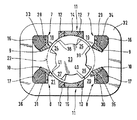
図1に示した本発明による電動モータにおけるステータ32は、パケットプレートにより構成され、その中心に位置する収容スペース内に4対のステータポール18, 19, 20, 21が突出する配置とされている。ステータポール18, 19, 20, 21の接触面38, 39, 40, 41は、ステータ32の中心に向けられている。これらの接触面38, 39, 40, 41により形成される包絡線22の内側には、4個のロータポール24, 25, 26, 27を有するロータ23が配置されている。
【0017】
図2に示すように、ステータ32の両側に絶縁素子1, 2が配置され、これら絶縁素子からは支持素子7, 8がステータ32の内方に向けて突出する。支持素子7, 8は、ステータ32に沿って配置され、その全長の二分の一の長さに亙って延在する。両絶縁素子1, 2は、ステータ32の両側に当接したときに支持素子7, 8における遊端領域の側部と協働する。
【0018】
絶縁素子1, 2の形状は、ステータ32の側方投影面の形状にほぼ対応する。ステータ32から離間した側で、ほぼ環状ディスク形状を呈する絶縁素子1, 2には突部5, 6が設けられている、これらの突部5, 6は、橋絡部3, 4を介して絶縁素子1, 2から離間した位置に配置されるものである。橋絡部3, 4はステータ32における収容スペースの主軸線に対してほぼ平行に延在し、ステータポール18, 19, 20, 21の接触面38, 39, 40, 41により形成される包絡線22の領域内に配置される。突部5, 6は、絶縁素子1, 2に対してほぼ平行に半径方向外方に向けて延在する。
【0019】
各ステータポール対18, 19; 20, 21と、突部5, 6により覆われる絶縁素子1, 2の領域を、コイル巻線により形成されたステータコイル16, 17によってそれぞれ包囲する。ステータポール対18, 19; 20, 21の側面およびステータコイル16, 17は、ステータ32における収容スペースの主軸線に対してほぼ平行に延在しており、これらの間に絶縁性を有する前記支持素子7, 8が配置されるものである。支持素子7, 8は絶縁素子1, 2と一体的に結合されており、非磁性の非金属材料、例えば合成樹脂材料から構成されるものである。
【0020】
支持素子7, 8は、ステータ32の長手方向軸線に対して直角の方向に拡大領域9, 10 を具えている。これら拡大領域9,10 は、ステータポール18, 19, 20, 21により形成される包絡線22に部分的に沿って延在する。拡大領域9, 10によりステータ32の長手方向軸線に向けられた収容凹部33, 34, 35, 36が形成され、これらの凹部はコイル巻線を機械的に導入したときにステータポール18, 19, 20, 21の側面28, 29, 30, 31からのコイル巻線の滑り出しを防止する機能を発揮するものである。
【0021】
絶縁素子1には、支持素子7と平行に延在する支持部11が設けられている。各支持部11はそれぞれ永久磁石14, 15を支持するものであって、絶縁素子1におけるステータ32との対向面から直角に突出する配置とされている。支持部11は相互に平行に延在する一対の絶縁性支持部分12から構成され、これら支持部分12は対向する遊端領域で結合橋部13により相互に結合されている。支持部分12は、ステータポール対18, 19, 20, 21の側面と永久磁石14, 15の間でステータ32の全長に亙って延在する。また、各永久磁石14, 15も、ステータ32の全長に亙って延在する。
【0022】
絶縁素子1、支持素子11に配置された支持部12および結合橋部13は、永久磁石14, 15の外形輪郭形状に対応する形状の収容スペースを形成する。永久磁石14, 15の外形輪郭形状と支持部の輪郭形状とが相補的に形状結合されるため、支持部12からの永久磁石14, 15の脱落を阻止することが可能である。
【0023】
支持部12は、両絶縁素子1, 2がステータ32の端面に当接する際に、結合橋部13の領域で絶縁素子2におけるガイド領域37と形状結合可能とされている。
【0024】
絶縁素子1, 2、支持部11および支持素子7, 8は、いずれも非磁性の非金属材料、例えば合成樹脂材料から構成されるものである。
【図面の簡単な説明】
【図1】図1は、本発明の一実施形態による電動モータを示す断面図である。
【図2】図2は、図示しないステータポール対の領域内における絶縁素子を、ステータコイルを省略した状態で示す拡大図である。
【符号の説明】
1, 2 絶縁素子
7, 8 絶縁性の支持素子
11 絶縁素子一方から突出する支持部
12 絶縁性支持部分
14, 15 永久磁石
16, 17 ステータコイル
18, 19, 20, 21 ステータポール
22 包絡線
23 ロータ
28, 29, 30, 31 ステータポール対の側面
32 ステータ
38, 39, 40, 41 ステータポールの接触面[0001]
【Technical field】
The present invention relates to an electric motor, in particular, a stator having a housing space in the center for a rotor, at least four stator poles projecting into the housing space in pairs, and a stator coil partially surrounding an insulating element And an electric motor comprising a permanent magnet disposed between a pair of stator poles.
[0002]
[Background]
In an electric motor having a stator pole, two types of methods are known for introducing a stator coil into the stator. That is, after the stator coil is finished outside the stator, it can be mounted on the stator pole inside the stator. It is also possible to wind the stator coil directly in the stator made of the packet plate.
[0003]
An electric motor that finishes a coil winding into a substantially annular stator coil outside the stator cannot be economically manufactured. This is because each step of the manufacturing process takes time, and the coil forming apparatus required for winding the stator coil is expensive.
[0004]
In an electric motor in which a stator coil is wound directly in a stator, a back cut is formed in the stator pole region, thereby preventing the stator coil from coming out of the stator pole. Due to this backcut, the stator becomes large, and thus an increase in weight is inevitable.
[0005]
Such an increase in weight is regarded as a problem in an electric motor in which a permanent magnet is disposed between two stator poles because the permanent magnet also has a large weight. This type of electric motor is disclosed in European Patent No. 0 564 516.
[0006]
[Problems of the Invention]
Accordingly, an object of the present invention is to provide an electric motor capable of winding a coil winding in a stator without substantial increase in weight and preventing the coil winding from coming out of the stator at that time. It is to propose. Furthermore, in the present invention, a simple and economical configuration for fixing the permanent magnet can be obtained.
[0007]
[Means for Solving the Problems]
In order to solve the above-described problems, the present invention partially includes a stator having a receiving space for a rotor in the center, at least four stator poles that project into the receiving space in pairs, and an insulating element. In an electric motor comprising an enclosing stator coil and a permanent magnet disposed between a pair of stator poles, the insulating element is disposed on each end face of the stator, and the main axis of the accommodation space in the stator, and An insulating support element is disposed between the side surfaces of the pair of stator poles extending in parallel with each other and the stator coil, and these support elements cooperate with at least one of the insulating elements, and from one of the insulating elements, a permanent magnet At least two support portions for supporting the projection protrude .
[0008]
It is preferable that at least a part of the support element is configured to extend along an envelope formed by the contact surface of the stator pole. In this case, when the coil winding is mechanically introduced, the support element extends substantially perpendicular to the main axis of the receiving space in the stator and forms a receiving recess directed to the main axis. Prevents the stator pole from coming off.
[0009]
For easy setting and positioning of the support element in the stator, it is preferred that the support element and both insulating elements are integrally formed.
[0010]
In order to improve insulation performance and reduce weight, the support element is preferably molded from synthetic resin.
[0011]
To enable installation of the permanent magnet quickly and easily in the stator, the present invention is, from one of the insulating elements, in which to project the at least two supporting portions for supporting the permanent magnet. Thereby, when the insulating element is disposed on the end face of the stator, the permanent magnet held by the support portion is introduced into the stator and positioned.
[0012]
In order to formally connect the permanent magnet and the support portion, each support portion is composed of at least two insulating support portions extending in parallel to each other, and these support portions are disposed between the side surfaces of the stator pole pair and the permanent magnet. It is preferable that the configuration is arranged in the above. Thereby, the permanent magnet arrange | positioned between two support parts is fixed to an axial direction with respect to a support element.
[0013]
In order to improve the insulation performance and reduce the weight, it is desirable to form the support portion from a synthetic resin.
[0014]
Each support portion accommodates a permanent magnet inside the stator and is centered. For example, the support portion is composed of two storage chambers whose free ends are open, and these storage chambers are arranged with respect to the main axis of the storage space in the stator. In parallel, the arrangement can extend over only a part of the entire length of the stator. In this case, the accommodating chambers extending coaxially with each other can be disposed in both insulating elements. In the assembled state, each storage chamber stores at least a part of the permanent magnet.
[0015]
[Embodiment]
Hereinafter, the present invention will be described in detail with reference to the illustrated preferred embodiments.
[0016]
The
[0017]
As shown in FIG. 2, insulating
[0018]
The shapes of the
[0019]
The regions of the
[0020]
The
[0021]
The insulating element 1 is provided with a
[0022]
The insulating element 1, the
[0023]
The
[0024]
The insulating
[Brief description of the drawings]
FIG. 1 is a cross-sectional view showing an electric motor according to an embodiment of the present invention.
FIG. 2 is an enlarged view showing an insulating element in a region of a stator pole pair (not shown) in a state where a stator coil is omitted.
[Explanation of symbols]
1, 2 Isolation element
7, 8 Insulating support element
11 Supporting part protruding from one side of the isolation element
12 Insulating support
14, 15 Permanent magnet
16, 17 Stator coil
18, 19, 20, 21 Stator pole
22 Envelope
23 Rotor
28, 29, 30, 31 Sides of stator pole pair
32 stator
38, 39, 40, 41 Contact surface of stator pole
Claims (6)
Applications Claiming Priority (2)
| Application Number | Priority Date | Filing Date | Title |
|---|---|---|---|
| DE19622186:2 | 1996-06-03 | ||
| DE19622186A DE19622186A1 (en) | 1996-06-03 | 1996-06-03 | Electric motor |
Publications (2)
| Publication Number | Publication Date |
|---|---|
| JPH1056745A JPH1056745A (en) | 1998-02-24 |
| JP3911552B2 true JP3911552B2 (en) | 2007-05-09 |
Family
ID=7795976
Family Applications (1)
| Application Number | Title | Priority Date | Filing Date |
|---|---|---|---|
| JP14489597A Expired - Lifetime JP3911552B2 (en) | 1996-06-03 | 1997-06-03 | Electric motor |
Country Status (5)
| Country | Link |
|---|---|
| US (1) | US5821661A (en) |
| EP (1) | EP0812050B1 (en) |
| JP (1) | JP3911552B2 (en) |
| CN (1) | CN1099747C (en) |
| DE (2) | DE19622186A1 (en) |
Families Citing this family (22)
| Publication number | Priority date | Publication date | Assignee | Title |
|---|---|---|---|---|
| US6584813B2 (en) | 2001-03-26 | 2003-07-01 | Emerson Electric Co. | Washing machine including a segmented stator switched reluctance motor |
| US6744166B2 (en) | 2001-01-04 | 2004-06-01 | Emerson Electric Co. | End cap assembly for a switched reluctance electric machine |
| US6700284B2 (en) | 2001-03-26 | 2004-03-02 | Emerson Electric Co. | Fan assembly including a segmented stator switched reluctance fan motor |
| US6897591B2 (en) | 2001-03-26 | 2005-05-24 | Emerson Electric Co. | Sensorless switched reluctance electric machine with segmented stator |
| US7012350B2 (en) | 2001-01-04 | 2006-03-14 | Emerson Electric Co. | Segmented stator switched reluctance machine |
| WO2005027306A2 (en) | 2003-09-05 | 2005-03-24 | Black & Decker Inc. | Field assemblies and methods of making same |
| US7078843B2 (en) | 2003-09-05 | 2006-07-18 | Black & Decker Inc. | Field assemblies and methods of making same |
| US7205696B2 (en) | 2003-09-05 | 2007-04-17 | Black & Decker Inc. | Field assemblies having pole pieces with ends that decrease in width, and methods of making same |
| US7211920B2 (en) | 2003-09-05 | 2007-05-01 | Black & Decker Inc. | Field assemblies having pole pieces with axial lengths less than an axial length of a back iron portion and methods of making same |
| KR100568788B1 (en) * | 2004-07-27 | 2006-04-07 | 엘지전자 주식회사 | Switched reluctance motor |
| EP2568573A3 (en) | 2005-03-07 | 2014-06-04 | Black & Decker Inc. | Power Tools with Motor Having a Multi-Piece Stator |
| JP2008035603A (en) * | 2006-07-27 | 2008-02-14 | Showa Corp | Rotating electric machine |
| DE102007023606A1 (en) * | 2007-05-21 | 2008-12-04 | Siemens Ag | Tooth module for a primary part of an electrical machine |
| CN101803149A (en) * | 2007-09-25 | 2010-08-11 | Bsh博世和西门子家用器具有限公司 | Coil holder for fixing stator winding heads of an electric motor |
| JP4535147B2 (en) * | 2008-02-29 | 2010-09-01 | 株式会社デンソー | Rotating electric machine stator and rotating electric machine |
| CN102347669A (en) * | 2010-08-05 | 2012-02-08 | 中国江南航天工业集团林泉电机厂 | Limited angle torque motor and method for manufacturing same |
| EP2466726A1 (en) * | 2010-12-20 | 2012-06-20 | Siemens Aktiengesellschaft | Permanent magnet for a permanent magnet machine |
| TR201103641A2 (en) * | 2011-04-14 | 2012-11-21 | General Electric Company | Electrical machine component mounting bracket |
| BR102013018363A2 (en) * | 2013-07-18 | 2015-07-21 | Whirlpool Sa | Switched reluctance electric motor |
| JP5846224B2 (en) * | 2014-01-22 | 2016-01-20 | トヨタ自動車株式会社 | Stator |
| FR3067880B1 (en) * | 2017-06-15 | 2020-07-17 | Moteurs Leroy-Somer | ROTATING ELECTRIC MACHINE |
| FR3069118B1 (en) * | 2017-07-17 | 2020-10-02 | Liebherr Aerospace Toulouse | TORQUE MOTOR INCLUDING A SUPPORT FOR WINDING THE STATOR COILS AND ASSEMBLY METHOD OF SUCH A TORQUE MOTOR |
Family Cites Families (11)
| Publication number | Priority date | Publication date | Assignee | Title |
|---|---|---|---|---|
| US2999176A (en) * | 1956-06-30 | 1961-09-05 | Electrolux Ab | Stator for dynamo-electric machines |
| US3609427A (en) * | 1970-05-13 | 1971-09-28 | Gould Inc | Field coil structure for electric motor |
| FR2126691A5 (en) * | 1971-02-11 | 1972-10-06 | Licentia Gmbh | |
| US3984711A (en) * | 1975-04-07 | 1976-10-05 | Warner Electric Brake & Clutch Company | Variable reluctance step motor with permanent magnets |
| DE3617017A1 (en) * | 1986-05-21 | 1987-11-26 | Bosch Gmbh Robert | STATOR FOR AN ELECTRICAL MACHINE |
| US4816710A (en) * | 1988-01-22 | 1989-03-28 | Prestolite Electric Incorporated | Field assembly insulator |
| US4975611A (en) * | 1988-11-07 | 1990-12-04 | Rochester D Eugene | Insert sheet for insulating the field winding of an electric motor |
| DE4002577A1 (en) * | 1990-01-30 | 1991-08-01 | Bosch Gmbh Robert | BRACKET FOR EXCITATION OF AN ELECTRIC MOTOR |
| SE467852B (en) * | 1990-12-28 | 1992-09-21 | Vilmos Toeroek | ELECTRIC ENGINE |
| US5331246A (en) * | 1992-12-30 | 1994-07-19 | Dana Corporation | Coil assembly retainer for electric motor |
| US5444318A (en) * | 1994-02-22 | 1995-08-22 | Black & Decker Inc. | Motor with permanent magnet actuated brake |
-
1996
- 1996-06-03 DE DE19622186A patent/DE19622186A1/en not_active Withdrawn
-
1997
- 1997-05-06 DE DE59705336T patent/DE59705336D1/en not_active Expired - Lifetime
- 1997-05-06 EP EP97810282A patent/EP0812050B1/en not_active Expired - Lifetime
- 1997-06-02 CN CN97105485A patent/CN1099747C/en not_active Expired - Lifetime
- 1997-06-03 US US08/868,197 patent/US5821661A/en not_active Expired - Lifetime
- 1997-06-03 JP JP14489597A patent/JP3911552B2/en not_active Expired - Lifetime
Also Published As
| Publication number | Publication date |
|---|---|
| EP0812050A1 (en) | 1997-12-10 |
| DE59705336D1 (en) | 2001-12-20 |
| US5821661A (en) | 1998-10-13 |
| DE19622186A1 (en) | 1997-12-04 |
| CN1099747C (en) | 2003-01-22 |
| EP0812050B1 (en) | 2001-11-14 |
| JPH1056745A (en) | 1998-02-24 |
| CN1167358A (en) | 1997-12-10 |
Similar Documents
| Publication | Publication Date | Title |
|---|---|---|
| JP3911552B2 (en) | Electric motor | |
| KR102073005B1 (en) | Motor | |
| GB2172444A (en) | Stator for an electric motor | |
| US2999176A (en) | Stator for dynamo-electric machines | |
| WO2004082101A2 (en) | Stator of reciprocating motor | |
| US7215059B1 (en) | Reluctance motor with at least two salient poles each provided with an exciter winding, and method for manufacturing the stator of such reluctance motor | |
| JP2001218409A (en) | Stator of motor | |
| JPH10174317A (en) | Motor stator and motor frame | |
| JPH06511378A (en) | electric machine | |
| JP6429400B2 (en) | Stator core, stator and rotating electric machine | |
| JPH0526917Y2 (en) | ||
| JP2002027707A5 (en) | ||
| JPH1189123A (en) | Motor provided with auxiliary magnetic circuit | |
| JPH02269430A (en) | Salient-pole rotor for rotary electric machine | |
| JP3575987B2 (en) | Motor stator | |
| JP2886083B2 (en) | Motor stator | |
| JPH04271240A (en) | Stator of electric motor and manufacture of nonformed wound electric motor stator | |
| JPH0139099Y2 (en) | ||
| JP2991748B2 (en) | Motor stator core | |
| JPH055807Y2 (en) | ||
| KR101799187B1 (en) | 8Magnet 17Slot 2Pitch Winding Pattern Motor | |
| JPH02303339A (en) | Electric motor | |
| JPH10108432A (en) | Motor | |
| JP2561135Y2 (en) | Armature for magnet generator | |
| JPH09219330A (en) | Ignition coil for internal combustion engine |
Legal Events
| Date | Code | Title | Description |
|---|---|---|---|
| A621 | Written request for application examination |
Free format text: JAPANESE INTERMEDIATE CODE: A621 Effective date: 20040422 |
|
| A131 | Notification of reasons for refusal |
Free format text: JAPANESE INTERMEDIATE CODE: A131 Effective date: 20060523 |
|
| A601 | Written request for extension of time |
Free format text: JAPANESE INTERMEDIATE CODE: A601 Effective date: 20060823 |
|
| A602 | Written permission of extension of time |
Free format text: JAPANESE INTERMEDIATE CODE: A602 Effective date: 20060828 |
|
| A521 | Written amendment |
Free format text: JAPANESE INTERMEDIATE CODE: A523 Effective date: 20061122 |
|
| TRDD | Decision of grant or rejection written | ||
| A01 | Written decision to grant a patent or to grant a registration (utility model) |
Free format text: JAPANESE INTERMEDIATE CODE: A01 Effective date: 20061219 |
|
| A61 | First payment of annual fees (during grant procedure) |
Free format text: JAPANESE INTERMEDIATE CODE: A61 Effective date: 20070104 |
|
| R150 | Certificate of patent or registration of utility model |
Free format text: JAPANESE INTERMEDIATE CODE: R150 |
|
| FPAY | Renewal fee payment (event date is renewal date of database) |
Free format text: PAYMENT UNTIL: 20100209 Year of fee payment: 3 |
|
| FPAY | Renewal fee payment (event date is renewal date of database) |
Free format text: PAYMENT UNTIL: 20110209 Year of fee payment: 4 |
|
| FPAY | Renewal fee payment (event date is renewal date of database) |
Free format text: PAYMENT UNTIL: 20120209 Year of fee payment: 5 |
|
| FPAY | Renewal fee payment (event date is renewal date of database) |
Free format text: PAYMENT UNTIL: 20120209 Year of fee payment: 5 |
|
| FPAY | Renewal fee payment (event date is renewal date of database) |
Free format text: PAYMENT UNTIL: 20130209 Year of fee payment: 6 |
|
| FPAY | Renewal fee payment (event date is renewal date of database) |
Free format text: PAYMENT UNTIL: 20130209 Year of fee payment: 6 |
|
| FPAY | Renewal fee payment (event date is renewal date of database) |
Free format text: PAYMENT UNTIL: 20140209 Year of fee payment: 7 |
|
| R250 | Receipt of annual fees |
Free format text: JAPANESE INTERMEDIATE CODE: R250 |
|
| R250 | Receipt of annual fees |
Free format text: JAPANESE INTERMEDIATE CODE: R250 |
|
| R250 | Receipt of annual fees |
Free format text: JAPANESE INTERMEDIATE CODE: R250 |
|
| R250 | Receipt of annual fees |
Free format text: JAPANESE INTERMEDIATE CODE: R250 |
|
| EXPY | Cancellation because of completion of term |