JP3910521B2 - Blood pressure measurement device - Google Patents
Blood pressure measurement device Download PDFInfo
- Publication number
- JP3910521B2 JP3910521B2 JP2002321076A JP2002321076A JP3910521B2 JP 3910521 B2 JP3910521 B2 JP 3910521B2 JP 2002321076 A JP2002321076 A JP 2002321076A JP 2002321076 A JP2002321076 A JP 2002321076A JP 3910521 B2 JP3910521 B2 JP 3910521B2
- Authority
- JP
- Japan
- Prior art keywords
- blood
- blood pressure
- flow velocity
- blood flow
- signal
- Prior art date
- Legal status (The legal status is an assumption and is not a legal conclusion. Google has not performed a legal analysis and makes no representation as to the accuracy of the status listed.)
- Expired - Fee Related
Links
Images


Description
【0001】
【発明の属する技術分野】
本発明は、人間の血圧を測定する方法の技術分野に属するものである。
【0002】
【従来技術】
今日、血圧を測定する方法として、カフ(圧迫帯)を用いないで常時測定する方法が提唱されている。このものは、一対の心電位電極と、該心電位電極からの心電位信号を処理する心電位処理手段と、指尖光電脈波検出センサと、該脈波信号を処理する脈波処理手段と、該処理された脈波をさらに二次微分する二次微分処理手段と、これら処理された心電位信号、脈波信号、脈波の二次微分信号に基づいて血圧を演算する演算手段と、この演算結果を表示する表示手段とを備えて構成し、そして演算手段が、心電位波形と脈波波形とから脈波伝播時間、脈波インターバル、そして心拍数を求め、これに基づいて血圧を演算するようにしている(例えば、特許文献1参照。)。
【0003】
また、人体の血液循環により生じる脈波を検出する脈波検出手段と、該検出された脈波信号から脈波伝播時間、脈波伝播速度の少なくとも一つを特徴量として演算する特徴量演算手段と、該演算された特徴量から血圧を演算する血圧演算手段とを備えて構成し、脈波を微分(一次微分)して脈波速度を演算し、さらにこれを微分(二次微分)して加速度脈波を演算し、ここから得られたデータを元に血圧を演算するようにしたものが提唱されている(例えば、特許文献2参照。)。
【0004】
また、血液循環によって生じる脈波から実測した実血圧値と、脈波検出手段から検出された脈波のセンサ値とを、異なる複数の血圧状態でそれぞれ測定してこれを標準関数として算出し、以降は、脈波検出手段で検出されるセンサ値を標準関数に代入して血圧値を算出するようにしたことを特徴とする血圧測定方法及び、血液循環によって生じる脈波から実測した実血圧値、並びに脈波検出をする脈波検出手段からのセンサ値を、異なる複数の血圧状態でそれぞれ測定したものについて算出した標準関数を記憶する記憶手段と、脈波検出手段で検出したセンサ値を前記記憶される標準関数に代入して血圧値を算出する血圧算出手段とを備えて構成されることを特徴とする血圧測定装置を用いて、標準関数を予め求めておくことで、脈波を検出して血圧測定をするようなものもある(例えば、特許文献3参照。)。
【0005】
【特許文献1】
特開平8−140948号公報 (第2−3頁)
【0006】
【特許文献2】
特開平10−295657号公報 (第2−3頁)
【0007】
【特許文献3】
特開2001−275998号広報 (第2−3頁)
【0008】
【発明が解決しようとする課題】
しかしながら、従来例にしめすような電位波形と脈波波形とから脈波伝播時間、脈波インターバル、そして心拍数を求め、これに基づいて血圧を演算する方法では、脈波伝播時間は血管の硬さにより伝播速度が変わってしまい、また、脈波とは血液の容積脈波強度を測定しているだけであり、血圧をあらわすために必要な血流速度を測定できていない。これでは正確な血圧を測定することが出来ない。また、脈波伝播時間、脈波伝播速度の少なくとも一つを特徴量として演算する特徴量演算手段と、該演算された特徴量から血圧を演算する血圧演算手段とを備えて構成し、脈波を微分(一次微分)して脈波速度を演算し、さらにこれを微分(二次微分)して加速度脈波を演算して、ここから得られたデータを元に血圧を求める方法も、脈波伝播時間、脈波伝播速度ともに血管表面を進む脈波であり、血管の硬さの影響を大きく受けてしまう。また、脈波を一次微分、二次微分したとしても、元々脈波とは血液の容積脈波強度を測定しているだけであり、すなわち血管径変化だけを捕らえていて、血圧をあらわすために必要な血流速度を測定できていない。また、異なる複数の血圧状態でそれぞれ測定して標準関数を算出して、脈波だけを検出して標準関数を用いて血圧を測定する場合においても、結局、脈波は血液の容積脈波強度を測定しているだけであるため、血圧をあらわすために必要な血流速度を測定できていない。
【0009】
従って、どの方法および装置においても、血圧の測定における測定時バラツキや人毎のバラツキが大きくなり正確な測定が困難である。
【0010】
【課題を解決するための手段】
本発明は、上記の課題を解決するために、容積脈波強度と血流速度成分を測定し、血圧を求める方法及び装置を考えた。血圧Vは血流量Qと血流抵抗Rの積により表される(式1)。
【0011】
血圧V=血流量Q×血流抵抗R (式1)
このうち、血流量Qは2式に表すような動脈径dと血流速度vの積のかたちで表される。
【0012】
血流量Q=(π×動脈径d×動脈径d×血流速度v)/8 (式2)
また、血流抵抗Rは動脈の中を流れる血液の粘度と動脈の径の比によって決まり、動脈径dが大きいほど血流抵抗Rが小さくなるという関係が成り立つ(式3)。
【0013】
血流抵抗R=ρ×C/d4 (式3)
ここで、ρは血液の粘度成分、Cは定数、dは動脈径である。これらの関係式を考慮して血圧を導き出そうとすると、脈波と呼ばれる容積脈波の強度変化は、実際には血液が脈動するときの動脈径の変化が容積変化として捕らえられているものであり、容積脈波を測定することにより動脈径dと相関した値を測定することができ、血管抵抗Rに相関する値を測定することが出来る。そして、動脈内の血流速度vを測定することにより血流量Qに相関する値も求めることができ、従って、血圧Vを測定することが出来る。
【0014】
そこで、本発明では生体表面から生体内部の血液に波動を送受信して、生体内部の血液の流れを検出する血流速度センサと、血流速度センサを駆動させる駆動部11と、血流速度センサからの信号の受信部12と、駆動部11と受信部12とを制御し血流速度を求める処理プログラムを実行する信号演算部13とを有し、
生体表面から生体内部の血液に光を送受信して、生体内部の血液の容積変化を検出する容積脈波センサと、容積脈波センサを駆動させる駆動部21と、容積脈波センサからの信号の受信部22と、駆動部21と受信部22とを制御し容積脈波強度を求める処理プログラムを実行する信号演算部23とを有し、
信号演算部13と信号演算部23からの演算結果を用いて血圧を求める信号演算部33を有する血圧測定装置を提供する。
【0015】
また、生体表面から生体内部の血液に波動を送受信して、生体内部の血液の流れを検出する血流速度センサと、血流速度センサを駆動させる駆動部41と、血流速度センサからの信号の受信部42と、駆動部41と受信部42とを制御し血流速度を求める処理プログラムを実行する信号演算部43と血流速度成分から強度スペクトルを分離し求める処理プログラムを実行する信号分離部44とを有し、
信号演算部43と信号分離部44からの演算結果を用いて血圧を求める血圧信号演算部45を有する血圧測定装置を提供する。
【0016】
また、血流速度センサは、送信用素子と受信用素子から構成し、しかも送信用素子と受信用素子の対は複数対あり、送受信する波動の進行方向と血液の流れる方向とのなす角度が対ごとに異なる血圧測定装置を提供する。
【0017】
また、前記対が2対である血圧測定装置を提供する。
【0018】
また、血流速度センサは、圧電素子を用いて構成する血圧測定装置を提供する。
【0019】
また、容積脈波センサは、光送信用素子と光受信用素子から構成し、光受信用素子が複数個ある血圧測定装置を提供する。
【0020】
また、光送信用素子の波長がヘモグロビンへの吸収率が高い波長である血圧測定装置を提供する。
【0021】
また、光送信用素子の光の波長が660nmにピークを持つ血圧測定装置を提供する。
【0022】
また、生体表面から生体内部の血液に波動を送受信して、生体内部の血液の流れを検出する血流速度センサと、血流速度センサの受信信号から血流速度を求める処理プログラムを実行する信号演算部13を有し、
生体表面から生体内部の血液に光を送受信して、生体内部の血液の容積変化を検出する容積脈波センサと、容積脈波センサの受信信号から容積脈波強度を求める処理プログラムを実行する信号演算部23を有し、
信号演算部13では血液の流れに反射することによって生じる波動のドップラシフト周波数から血流速度vを求め、信号演算部23では血液中のヘモグロビンに吸収される光の量から容積脈波強度を求め、容積脈波強度の変化は流れている動脈の径変化に相関することから動脈径dを求め、動脈径dと血流速度vから動脈の血流量Qを求め、動脈径dが血管抵抗Rに逆比例することから血管抵抗Rを求め、血流量Qと血管抵抗Rを用いて血圧Vを求める血圧測定方法を提供する。
【0023】
また、生体表面から生体内部の血液に波動を送受信して、生体内部の血液の流れを検出する血流速度センサと、血流速度センサを駆動させる駆動部41と、血流速度センサからの信号の受信部42と、駆動部41と受信部42とを制御し血流速度を求める処理プログラムを実行する信号演算部43と血流速度成分から強度スペクトルを分離し求める処理プログラムを実行する信号分離部44とを有し、
信号演算部43では血液の流れに反射することによって生じる波動のドップラシフト周波数から血流速度vを求め、信号分離部44では前記ドップラシフト周波数の強度分布から血流速度の強度スペクトルPを求め、血流速度の強度スペクトルPは動脈を流れる血流の容積変化と比例することから容積脈波強度を求め、容積脈波強度の変化は流れている動脈の径変化に相関することから動脈径dを求め、動脈径dと血流速度vから動脈の血流量Qを求め、動脈径dが血管抵抗Rに反比例することから血管抵抗Rを求め、血流量Qと血管抵抗Rを用いて血圧Vを求める血圧測定方法を提供する。
【0024】
また、動脈径dが脈動に応じて径変化しているときの最大径dmaxと、血流速度Vが脈動に応じて速度変化しているときの最大速度vmaxとから最大血流量Qmaxを求め、
最大径dmaxからもとめた血管抵抗Rminと最大血流量Qmaxを用いて収縮期血圧のVmaxを求める血圧測定方法を提供する。
【0025】
また、動脈径dが脈動に応じて径変化しているときの最小径dminと、血流速度Vが脈動に応じて速度変化しているときの最小速度vminとから最小血流量Qminを求め、
最小径dminからもとめた血管抵抗Rmaxと最小血流量Qminを用いて拡張期血圧のVminを求める血圧測定方法を提供する。
【0026】
また、カフを用いる従来の血圧計を用いて収縮期実血圧Vrmaxと拡張期実血圧Vrminを測定し、その測定と同時期に前記血流速度センサや前記容積脈波センサを用いて前記収縮期血圧Vmaxと拡張期血圧Vminを求め、収縮期血圧Vmaxから収縮期実血圧Vrmaxを計算する補正係数と、拡張期血圧Vminから拡張期実血圧Vrminを計算する補正係数をそれぞれ求め、
カフを用いる血圧計を使用しないで、血流速度センサのみや血流速度センサと容積脈波センサのみを用いて測定したときには、収縮期血圧Vmaxと補正係数を用いて収縮期実血圧を求め、拡張期血圧Vminと補正係数を用いて拡張期実血圧を算出する血圧測定方法を提供する。
【0027】
また、カフを用いる従来の血圧計を用いて収縮期実血圧Vrmaxと拡張期実血圧Vrminを測定し、その測定と同時期に血流速度センサや容積脈波センサを用いて収縮期血圧Vmaxと拡張期血圧Vminを求め、収縮期血圧Vmaxから収縮期実血圧Vrmaxを計算する補正係数と、収縮期血圧Vmaxと拡張期血圧Vminの差(Vmax−Vmin)から収縮期実血圧Vrmaxと拡張期実血圧Vrminの差(Vrmax−Vrmin)を計算する補正係数を求め、
カフを用いる血圧計を使用しないで、血流速度センサや血流速度センサと容積脈波センサのみを用いて測定したときには、
収縮期血圧Vmaxと補正係数を用いて収縮期実血圧を求め、収縮期血圧Vmaxと拡張期血圧Vminの差と補正係数を用いて拡張期実血圧を算出する血圧測定方法を提供する。
【0028】
【発明の実施の形態】
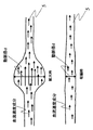
次に、本発明の実施の形態について、図面に基づいて説明する。図1は本発明の血圧測定手段をあらわす回路ブロック図である。本発明の血圧測定原理は血流速度vと容積脈波強度を用いて血流量Qに相関する値を導き出し、容積脈波強度から血流抵抗に相関する値を導き出し、血流量Qと血流抵抗Rの積から血圧Vに相関する値を導き出すものである。そこで、血流速度と容積脈波強度を求めるために図1に示すようなセンサと回路構成を用いる。血流速度センサ及びその回路ブロックについて説明する(図1及び図2参照)。血流速度は超音波を利用して測定する。先ず、生体4の表面である皮膚面から超音波の波動を駆動部11から血流速度センサ10を駆動して送信する。そして動脈5を流れる血液より反射してくる超音波を血流速度センサ10を通して受信部12で受信する。この受信信号には血流速度が送信波動のドップラシフト信号となって存在する。そこで、駆動部11の基本波動と受信部12の受信波動をミキシングして信号演算部13で検波を行うことによりドップラシフト周波数成分のみを抽出する。さらに、信号演算部13ではこのドップラ周波数成分Δfと、波動と動脈5のなす角 θより4式を用いて血流速度を求める。
【0029】
v=ε・Δf/(2f・cosθ) (式4)
ここで、εは生体内の音速、fは入力した波動の周波数、vは血流速度、θは動脈と波動のなす角である。前記の方法で4式を用いて血流速度を求めるためには、動脈と波動のなす角θが既知である必要がある。しかしながら、動脈の位置が正確に把握できている場合は少ないので、図2に示すような複数個の血流速度センサを用いてθが未知な場合についても血流速度が求められるように、2個の血流速度センサを用いて測定する血流の流れる方向に対して角度θと角度θ−αの2つの超音波波動が送受信できるセンサを作製した。すなわち、生体表面から内部に波動を送受信する血流速度センサ10は1対となる。血流速度センサがそれぞれ受信するドップラシフト信号Δf0及びΔf1、そして2個の血流速度センサのなす角をαとすると5式を用いてθを求めることができる。
【0030】
θ=tan-1(Δf1/Δf0−cosα)/sinα (式5)
そして、ここで求めたθとΔf0をΔf=Δf0として4式に代入することにより、血流速度vを求めることができる。また、ここで、血流速度センサを2個以上にし、θを数多く算出して平均をとる方法を用いても、θの測定精度が上がるのでさらに良い。
【0031】
次に、容積脈波強度の測定するための容積脈波センサ及びその回路ブロックについて説明する(図1と図3参照)。容積脈波強度は光を利用して測定する。先ず、生体4の皮膚面から光の駆動部21から光送信用素子201を駆動して光を送信する。そして生体内部を伝わる光は生体組織や動脈5を流れる血液により吸収され、反射してきた光が光受信用素子202を通して受信部22に入る。この受信信号には血液によって吸収された成分と生体組織によって吸収された信号が混在する。そこで、受信部22から得られた信号を信号演算部23では血液成分によって吸収された量を抽出し、その吸収量変化が血液量変化と比例することから血液の容積脈波強度を算出している。演算方法について図3を用いて説明する。光送信用素子は血液に大きく吸収されるように、血液中のもっもと多くの成分であるヘモグロビンに吸収率の大きい波長にピークを持つ光を生体内部の動脈血に向けて照射する。今回の実施の形態では660nmにピークを持つLEDを用いた。そして、入射した光は生体組織を通過し動脈内に進入する。そして、血液中のヘモグロビンに大きく吸収され、そのうちの反射波が光受信用素子202に到達する。ここで、血液の吸収成分だけを捕らえるために光源の同心円状に数mmずらして2個の光受信用素子202を設置する。このときの生体組織の吸収係数μ0、ヘモグロビンの吸収係数μ1とすると、数mmずらして置いた2個の光受信用素子202のに到達するまでの吸収量の総和は、6式と7式で表される。
【0032】
(入射航路L1+反射航路L5)×μ0+(入射航路L2+反射航路L4)×μ1 (式6)
(入射航路L1+反射航路L7)×μ0+(入射航路L2+入射航路L3+反射航路L6)×μ1(式7)
ここでL1〜L7は光路長である。そして、2個の光受信用素子202はほぼ同じ場所に位置するため、反射航路L5と反射航路L7はほとんど同じ長さであると考えられる。そこで、L7=L5とおいて7式を書き直すと8式となる。
(入射航路L1+反射航路L5)×μ0+(入射航路L2+入射航路L3+反射航路L6)×μ1(式8)
今、光の信号の中のヘモグロビンに吸収された量だけが必要で、生体組織に吸収された強度は測定誤差となる。測定誤差を無くすには生体組織の吸収係数μ0の項を消去すればよい。それは6式から8式を引くことにより実現できる。
(入射航路L2+反射航路L4)×μ1−(入射航路L2+入射航路L3+反射航路L6)×μ1(式9)
これを変形して、
(反射航路L4−入射航路L3−反射航路L6)×μ1 (式10)
この10式は純粋に血液中のヘモグロビンによって吸収された量だけを表す式となっている。すなわち、容積脈波強度は10式で表される。
【0033】
また、容積脈波強度の測定精度を上げていくためには、光源を複数用意してそれぞれの光源に対して前記方法を用い、それらの結果を平均していくことにより精度を上げていくことができる。
【0034】
信号演算部13からの血流速度信号と信号演算部23からの容積脈波強度信号が血圧信号演算部33に入力される。血圧信号演算部33ではこれらの信号から血圧信号を演算する。演算の方法を下記に示す。図4は動脈内部を血液が血流となって流れる様子のモデル図である。動脈内では脈拍に応じて動脈径が拡大と収縮を繰り返している。動脈径dの拡大が生じるとその部分の容積が増加する。そして動脈径dが収縮するとその部分の容積が減少する。すなわち、前記容積脈波強度は動脈径dの変化を見ていることになる。そこで、血圧信号演算部33では容積脈波強度を動脈径dに置き換えて処理が行われる。血圧は1式に2式と3式を代入した11式より求められる。
【0035】
血圧V=C・ρ・π/8×v/d2 (式11)
動脈径dと血流速度vを11式に代入することにより血圧Vを算出する。ここで、C・ρ・π/8は定数となり、カフを用いて測定した血圧に対する係数項となる。この係数項は実際にカフを用いた従来の方法で血圧を実測して求めることができる。
【0036】
次に、もう一つの血圧測定手段を図面に基づいて説明する。図5は本発明の血圧測定手段をあらわすブロック図である。本発明のもう一つ血圧測定原理は血流速度vだけを用いて血流量Qに相関する値と血流抵抗に相関する値を導き出し、血流量Qと血流抵抗Rの積から血圧Vに相関する値を導き出すものである。そこで、血流速度から血圧を求めるために図5に示すようなセンサと回路構成を用いる。血流速度は超音波を利用して測定する。これは前記したドップラ周波数から求める方法と同じである。先ず、生体4の皮膚面から超音波の波動を駆動部41から血流速度センサ10を駆動して送信する。そして動脈5を流れる血液より反射してくる超音波を血流速度センサ10を通して受信部42で受信する。この受信信号には血流速度が送信波動のドップラシフト信号となって存在する。そこで、駆動部41の基本波動と受信部42の受信波動をミキシングして信号演算部43で検波を行うことによりドップラシフト周波数成分のみを抽出する。さらに、信号演算部43ではこのドップラ周波数成分Δfと5式を用いて血流速度を求める。このようにして求めた血流速度信号は直接血圧信号演算部45に入力される。
【0037】
また信号演算部43ではドップラシフト波形を信号分離部44に送信する。ドップラシフト波形とは、もともとドップラシフト周波数はいろいろな成分を持っている。すなわち、この周波数成分の中には大小さまざまな速度成分が含まれていることになる(図6)。そこで信号分離部44ではこのドップラ周波数成分から大小さまざまな速度成分を代表する速度成分として、血流速度成分を高速フーリエ変換することにより血流速度の強度スペクトルPを求める。図6に動脈中の血流速度成分が分布するモデル図を示す。動脈内では脈拍に応じて血流速度が変化すると同時に血流速度成分量も変化し、強度スペクトルPも変化する。血流速度の強度スペクトルPが増加するということは、血流速度成分が増えているということであり、血流速度成分が増えるということは図6にも示すように、動脈の容積が増加していることになる。即ち、血流速度の強度スペクトルPとは動脈の容積に比例するものと考えることができ、つまり容積脈波強度に比例する信号と考えることができる。そこで、信号分離部44では血流速度の強度スペクトルPを求めることにより、ドップラシフト波形から容積脈波強度に比例する信号を分離する。そしてその信号を血圧信号演算部45に送信する。
【0038】
信号演算部43からの血流速度信号と信号分離部44からの容積脈波強度に比例する信号が血圧信号演算部45に入力される。血圧信号演算部45ではこれらの信号から血圧信号を演算する。演算の方法は前記の方法と同様である。容積脈波強度の比例する信号は動脈径dの変化に相関する。そこで、血圧信号演算部45では容積脈波強度の比例する信号を動脈径dに置き換えて処理が行われる。動脈径dと血流速度vを11式に代入することにより血圧Vを算出する。ここで、C・ρ・π/8は定数となり、カフを用いて測定した血圧に対する係数項となる。この係数項も実際にカフを用いた従来の方法で血圧を実測して求めることができる。
【0039】
(実施の形態1)
実施の形態1では血流速度センサ1と容積脈波センサ2を手首に装着してとう骨動脈51の血流を測定し、血圧を求めた。図7に説明図を示す。手首の内側のとう骨動脈51に対して超音波、及び光を照射できるような位置に血流速度センサ1と容積脈波センサ2を取り付ける。血流速度センサ1は前記したようにとう骨動脈51中を流れる血流に対して超音波を送受信し、信号演算部13により血流速度を求める。このとき、超音波の送受信部にはPZTからなる圧電素子を用いた。圧電素子のサイズは0.5×8mmで厚さ0.2mmのものをそれぞれ送信用と受信用に合計4個搭載した。また、超音波の送信周波数は9.6MHzを用いた。ドップラシフト周波数は最高で4K〜5KHzあり、血流速度は最高で1.0〜1.5m/s程度であった。容積脈波センサ2は光送信用素子201として1つのLEDと光受信用素子202として2つのフォトダイオードを用いた。光送信用素子201は660nmにピークを持つ光を出すものを採用した。これはヘモグロビンの吸収係数が660nm付近で高くなるためである。そして、光送信用素子201と光受信用素子202の間を5mm離して配置し、2つの光受信素子202間は2mm間隔をあけて配置した。光の駆動部21は光送信用素子201に10ms周期で5ms幅のパルスで2.5Vの電圧を加え発光させている。受信部22ではフォトダイオードの微小電流変化を1000倍の電圧変化になるように変換し、その後さらにアンプで3〜5倍に増幅している。これで十分な感度で受信部22では信号を受信できている。
【0040】
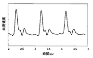
この装置を用いて実際に血圧測定を行った。図8に血流速度を測定した一例を示す。血流速度は脈拍に応じて変化し、心臓の収縮期では流速が速くなりピークを示し、拡張期では速度が遅くなりほぼ0となる。図9に容積脈波強度の一例を示す。図8に示した血流速度変化に対応した容積脈波強度変化である。血流速度と同様に脈拍に応じて強度が変化している。この容積脈波強度が動脈径dの変化を表すものとして測定を行った。実施の形態1では手首に半日装着して30分毎に15秒間血流速度と容積脈波強度を測定し下記の方法で血圧を算出した。また、確認のために、カフを用いる従来の血圧計も装着し同時に測定を行っている。血圧をあらわす場合、一般に心臓の収縮期血圧と拡張期血圧を指標としてあらわしている。そこで本発明においても、収縮期血圧と拡張期血圧を血圧の指標値として算出した。
【0041】
先ず、動脈径dの最大値dmaxと血流速度vの最大値vmaxから、2式を用いて最大血流量Qmaxを計算した。次にdmaxから、3式を用いて血管抵抗Rminを計算した。そして、1式を用いて最大血流量Qmaxと血管抵抗Rminを掛け合わすことにより収縮期血圧のVmaxを求めた。また、動脈径dの最小値dminと血流速度vの最小値vminから、2式を用いて最小血流量Qminを計算した。次にdminから、3式を用いて血管抵抗Rmaxを計算した。そして、1式を用いて最小血流量Qminと血管抵抗Rmaxを掛け合わすことにより拡張期血圧のVminを求めた。次に、カフを用いた従来の血圧計により測定した収縮期実血圧Vrmaxと拡張期実血圧Vrminを用いて、係数項に当たる補正係数を求めた。求め方は最小二乗近似を用いて最も誤差が小さくなるようにして求めている。例えば、カフを用いる従来の血圧計と同時に測定した本発明の収縮期血圧をVmax、拡張期血圧をVminとし、12、13式を作成する。
【0042】
Vrmax=A1+A2×Vmax (式12)
Vrmin=A3+A4×Vmin (式13)
ここで、A1、A2、A3、A4が補正係数である。この2つの式により求めた補正係数を14、15式に代入することで収縮期血圧と拡張期血圧を導出する。
【0043】
収縮期血圧=A1+A2×Vmax (式14)
拡張期血圧=A3+A4×Vmin (式15)
そして、この装置を手首につけて半日間データを取り、精度の確認を行った。このようにして求めた収縮期血圧について、例えばカフ実測値116mmHgに対して本発明114.9mmHg、カフ実測値129mmHgに対して本発明130.28mHgと近い値を示し、結果的には相関係数R2=0.8と良好な結果を示した。
【0044】
次に、もう一つの異なる方法を用いて拡張期血圧を求める方法を説明する。前記の方法で用いた補正係数A1、A2はそのまま用いる。次にカフによる測定値の収縮期実血圧Vrmaxと拡張期実血圧Vrminの差を求める。そして16式を用いて補正係数を最小二乗法により求める。
Vrmax−Vrmin=B1+B2×(Vmax−Vmin) (式16)
ここで、B1、B2が補正係数である。そしてこの式により求めた補正係数を用いて拡張期血圧を求める式を17式に示す。
【0045】
拡張期血圧=A1+A2×Vmax−B1+B2×(Vmax−Vmin) (式17)
前記の補正方法との違いは、拡張期血圧を求めるときに計測により求めたVminを用いずに、VmaxとVminの差を用いて補正係数を計算しているところである。この方法を用いたほうが収縮期血圧と拡張期血圧の差分を近似できるので補正精度が上がる。前記方法と同様に半日間の血圧変化を測定し、精度の確認を行っ結果、カフによる実測値と本方法による血圧測定値の相関は相関係数R2=0.85と良好な結果を示した。
【0046】
(実施の形態2)
実施の形態2では血流速度センサ1を手首に装着してとう骨動脈51の血流を測定し、血圧を求めた例を示す。図10に説明図を示す。手首の内側のとう骨動脈51に対して超音波を照射できる位置に血流速度センサ1を取り付ける。血流速度センサ1は前記したようにとう骨動脈51中を流れる血流に対して超音波を送受信し、信号演算部43により血流速度を求める。このときの超音波の送信周波数は9.6MHzを用いた。ドップラシフト周波数は最高で4K〜5KHzあり、血流速度は最高で1.0〜1.5m/s程度であった。血流速度センサ1としては実施の形態1に使用したものと同様の圧電素子を用いたセンサであるため、測定される血流速度は図8に示す例と同様のものである。信号の変化の様子も同様で、脈拍に応じて変化し、心臓の収縮期では流速が速くなりピークを示し、拡張期では速度が遅くなりほぼ0となる。
【0047】
次に血流速度センサ1の信号より容積脈波強度に比例する信号を分離する処理を行う。受信部42では血流速度センサの信号を20KHzの信号でサンプリングを行っている。このサンプリング信号に対して、25.6ms分のデータ(512個)を高速フーリエ変換(FFT)を行う。このとき計算されたパワースペクトルが25.6ms間に流れるそれぞれの速度成分ということになる。そこで、このパワースペクトルの和をとって、それを強度スペクトルPとした。この強度スペクトルPを25.6ms間隔でプロットすると、脈拍波形に同期した波形が得られ、しかも容積変化に対応する信号波形が得られていた。
【0048】
そこで、強度スペクトルPを容積脈波強度に比例する信号として、動脈径dの変化に置き換えて血圧の測定を行った。本実施の形態では血流速度センサを手首に半日装着して30分毎に15秒間血流速度と強度スペクトルPを測定し血圧を算出した。また、実施の形態1と同様に確認のために、カフを用いる従来の血圧計も装着し同時に測定を行っている。そして、収縮期血圧と拡張期血圧を血圧の指標値として算出し相関関係を比較した。
【0049】
算出方法は実施の形態1と同じである。最初にカフを用いて測定した実測値の収縮期血圧Vrmaxと拡張期血圧Vrminを用いて補正係数A1〜A4を求めた。そして、30分毎に半日間測定して、カフを用いた従来の血圧計により求めた収縮期血圧と拡張期血圧と本発明により求めた血圧値との相関係数を求めた。その結果、相関係数R2=0.78とたいへん良好な結果を示した。このことから、血流速度センサ1だけで測定しても十分血圧が測定できることがわかった。
【0050】
次に、実施の形態1にも示したもう一つの異なる方法を用いて拡張期血圧を求める。前記の方法で用いた補正係数A1、A2はそのまま用いて、カフによる測定値の収縮期実血圧Vrmaxと拡張期血圧Vrminの差を求め、16式を用いて補正係数B1、B2を求める。そして17式を用いて拡張期血圧を求めた。この方法を用いて、前記方法と同様に半日間の血圧変化を測定し、精度の確認を行っ結果、カフによる実測値と本方法による血圧測定値の相関は相関係数R2=0.83と良好な結果を示した。先程と同様に、この方法においても、血流速度センサ1だけで測定しても十分血圧が測定できることがわかった。
【0051】
また、今回の実施の形態では、血流速度センサ1及び容積脈波センサ2をとう骨動脈51を狙って手首に装着しているが、生体のどの動脈を狙って測定しても良い。カフを用いた血圧計により補正することにより、正確な血圧を求めることができる。また、今回は血流速度センサを1対用いているが、複数個用いても測定精度が上がるので多いほうが良い。また、容積脈波センサも光送信素子1個と光受信素子2個用いているが、素子数を増やすと測定精度が上がっていくので多いほうが良い。
【0052】
【発明の効果】
以上のように、本発明の血圧測定装置及び血圧測定法によれば、最初にカフを用いて測定した血圧値によって補正係数を求めておくだけで、その後はカフを使用すること無く精度良く血圧を測定することができ、常時装着可能な血圧測定装置の提供ができる。
【図面の簡単な説明】
【図1】本発明の実施の形態1の回路ブロック図である。
【図2】血流速度センサの説明図である。
【図3】容積脈波センサの説明図である。
【図4】動脈内部の血流容積と径変化モデル図である。
【図5】本発明の実施の形態2の回路ブロック図である。
【図6】動脈内部の血流速度成分分布と径変化モデル図である。
【図7】本発明の実施の形態1の各センサの装着説明断面図である。
【図8】血流速度センサが検出した血流速度変化グラフである。
【図9】容積脈波センサが検出した容積脈波強度変化グラフである。
【図10】本発明の実施の形態2の血流速度センサの装着説明断面図である。
【符号の説明】
1 血流速度センサ部
10 血流速度センサ
2 容積脈波センサ部
201 光送信用素子
202 光受信用素子
11 血流速度センサ駆動部
12 血流速度センサ受信部
13 信号演算部
21 容積脈波センサ駆動部
22 容積脈波センサ受信部
23 信号演算部
33 血圧信号演算部
41 血流速度センサ駆動部
42 血流速度センサ受信部
43 信号演算部
44 信号分離部
45 血圧信号演算部
4 生体
5 動脈
51 とう骨動脈[0001]
BACKGROUND OF THE INVENTION
The present invention belongs to the technical field of methods for measuring human blood pressure.
[0002]
[Prior art]
Today, as a method of measuring blood pressure, a method of constantly measuring without using a cuff (compression band) has been proposed. This includes a pair of cardiac potential electrodes, cardiac potential processing means for processing a cardiac potential signal from the cardiac potential electrodes, a fingertip photoelectric pulse wave detection sensor, and a pulse wave processing means for processing the pulse wave signal. Secondary differential processing means for further secondary differentiation of the processed pulse wave; arithmetic means for calculating blood pressure based on the processed cardiac potential signal, pulse wave signal, and secondary differential signal of the pulse wave; Display means for displaying the calculation result, and the calculation means obtains the pulse wave propagation time, the pulse wave interval, and the heart rate from the cardiac potential waveform and the pulse wave waveform, and based on this, calculates the blood pressure. The calculation is performed (for example, see Patent Document 1).
[0003]
Also, a pulse wave detecting means for detecting a pulse wave generated by blood circulation of a human body, and a feature amount calculating means for calculating at least one of a pulse wave propagation time and a pulse wave propagation speed as a feature amount from the detected pulse wave signal And blood pressure calculation means for calculating blood pressure from the calculated feature amount, and the pulse wave is differentiated (primary differentiation) to calculate the pulse wave velocity, and further differentiated (secondary differentiation). An acceleration pulse wave is calculated, and a blood pressure is calculated based on data obtained from the acceleration pulse wave (see, for example, Patent Document 2).
[0004]
In addition, the actual blood pressure value actually measured from the pulse wave generated by blood circulation and the sensor value of the pulse wave detected from the pulse wave detecting means are respectively measured in a plurality of different blood pressure states and calculated as a standard function, Thereafter, the blood pressure measurement method is characterized in that the blood pressure value is calculated by substituting the sensor value detected by the pulse wave detection means into the standard function, and the actual blood pressure value actually measured from the pulse wave generated by blood circulation A storage means for storing a standard function calculated for sensor values measured from a plurality of different blood pressure states, and a sensor value detected by the pulse wave detection means. A pulse wave is detected by obtaining a standard function in advance using a blood pressure measuring device characterized by comprising a blood pressure calculating means for calculating a blood pressure value by substituting it into a stored standard function While others such as the blood pressure measurement Te (e.g., see
[0005]
[Patent Document 1]
JP-A-8-140948 (page 2-3)
[0006]
[Patent Document 2]
JP-A-10-295657 (page 2-3)
[0007]
[Patent Document 3]
Japanese Laid-Open Patent Publication No. 2001-275998 (Page 2-3)
[0008]
[Problems to be solved by the invention]
However, in the method of calculating the pulse wave propagation time, the pulse wave interval, and the heart rate from the potential waveform and the pulse wave waveform as shown in the conventional example and calculating the blood pressure based on the pulse wave propagation time, the pulse wave propagation time is determined as the blood vessel hardness. Accordingly, the propagation velocity changes, and the pulse wave only measures the volume pulse wave intensity of blood, and the blood flow velocity necessary for representing the blood pressure cannot be measured. This makes it impossible to accurately measure blood pressure. Further, the apparatus includes a feature amount calculation unit that calculates at least one of the pulse wave propagation time and the pulse wave propagation speed as a feature amount, and a blood pressure calculation unit that calculates a blood pressure from the calculated feature amount. Can also be obtained by calculating the pulse wave velocity by differentiating (primary differentiation), further differentiating (secondary differentiation) to calculate the acceleration pulse wave, and obtaining the blood pressure based on the data obtained from this, Both the wave propagation time and the pulse wave velocity are pulse waves that travel on the surface of the blood vessel and are greatly affected by the hardness of the blood vessel. In addition, even if the pulse wave is first- and second-order differentiated, the pulse wave originally only measures the volume pulse wave intensity of the blood, that is, to capture only the change in blood vessel diameter and express the blood pressure. The necessary blood flow velocity cannot be measured. In addition, even when measuring a blood pressure using a standard function by calculating a standard function by measuring each of a plurality of different blood pressure states and detecting only the pulse wave, the pulse wave is ultimately a blood volume pulse wave intensity. Therefore, the blood flow velocity necessary for representing the blood pressure cannot be measured.
[0009]
Accordingly, in any method and apparatus, variation in blood pressure measurement and variation from person to person are large, and accurate measurement is difficult.
[0010]
[Means for Solving the Problems]
In order to solve the above-mentioned problems, the present invention has conceived a method and an apparatus for measuring blood volume pulse wave intensity and blood flow velocity component to obtain blood pressure. The blood pressure V is expressed by the product of the blood flow rate Q and the blood flow resistance R (Equation 1).
[0011]
Blood pressure V = blood flow volume Q × blood flow resistance R (Formula 1)
Of these, the blood flow rate Q is represented by the product of the arterial diameter d and the blood flow velocity v as expressed in equation (2).
[0012]
Blood flow volume Q = (π × arterial diameter d × arterial diameter d × blood flow velocity v) / 8 (Formula 2)
The blood flow resistance R is determined by the ratio of the viscosity of blood flowing through the artery and the diameter of the artery, and the relationship that the blood flow resistance R decreases as the artery diameter d increases (Formula 3).
[0013]
Blood flow resistance R = ρ × C / d 4 (Formula 3)
Here, ρ is a blood viscosity component, C is a constant, and d is an artery diameter. When trying to derive the blood pressure in consideration of these relational expressions, the intensity change of the volume pulse wave called the pulse wave is actually a change in the arterial diameter when the blood pulsates is captured as a volume change By measuring the volume pulse wave, a value correlated with the artery diameter d can be measured, and a value correlated with the vascular resistance R can be measured. Then, by measuring the blood flow velocity v in the artery, a value correlated with the blood flow rate Q can also be obtained, and thus the blood pressure V can be measured.
[0014]
Therefore, in the present invention, a blood flow velocity sensor that detects the flow of blood inside the living body by transmitting and receiving waves from the surface of the living body to the blood inside the living body, a drive unit 11 that drives the blood flow velocity sensor, and a blood flow velocity sensor And a signal calculation unit 13 that executes a processing program for controlling the drive unit 11 and the reception unit 12 to obtain a blood flow velocity.
A volume pulse wave sensor that detects the volume change of blood inside the living body by transmitting and receiving light from the surface of the living body to the blood inside the living body, a drive unit 21 that drives the volume pulse wave sensor, and a signal from the volume pulse wave sensor A receiving unit 22, a signal calculating unit 23 for controlling the driving unit 21 and the receiving unit 22 to execute a processing program for obtaining volume pulse wave intensity;
A blood pressure measurement device having a signal calculation unit 33 for obtaining blood pressure using calculation results from the signal calculation unit 13 and the signal calculation unit 23 is provided.
[0015]
In addition, a blood flow velocity sensor that detects the flow of blood inside the living body by transmitting and receiving waves from the living body surface to the blood inside the living body, a drive unit 41 that drives the blood flow velocity sensor, and a signal from the blood flow velocity sensor The signal processing unit 43 that controls the receiving unit 42, the driving unit 41, and the receiving unit 42 to execute the processing program for obtaining the blood flow velocity and the signal separation that executes the processing program for separating and obtaining the intensity spectrum from the blood flow velocity component Part 44,
A blood pressure measurement device having a blood pressure signal calculation unit 45 that obtains blood pressure using the calculation results from the signal calculation unit 43 and the signal separation unit 44 is provided.
[0016]
The blood flow velocity sensor is composed of a transmitting element and a receiving element, and there are a plurality of pairs of transmitting elements and receiving elements, and the angle formed between the traveling direction of wave to be transmitted and received and the direction of blood flow is A different blood pressure measuring device is provided for each pair.
[0017]
Also provided is a blood pressure measurement device in which the pair is two pairs.
[0018]
Moreover, the blood flow velocity sensor provides a blood pressure measurement device configured using a piezoelectric element.
[0019]
The volume pulse wave sensor includes a light transmitting element and a light receiving element, and provides a blood pressure measuring device having a plurality of light receiving elements.
[0020]
In addition, a blood pressure measurement device is provided in which the wavelength of the optical transmission element is a wavelength having a high absorption rate into hemoglobin.
[0021]
Also provided is a blood pressure measuring device having a peak of light wavelength of the light transmitting element at 660 nm.
[0022]
In addition, a blood flow velocity sensor for transmitting and receiving waves from the surface of the living body to the blood inside the living body to detect the blood flow inside the living body, and a signal for executing a processing program for obtaining the blood flow velocity from the received signal of the blood flow velocity sensor An arithmetic unit 13;
A volume pulse wave sensor that detects the volume change of blood inside the living body by transmitting / receiving light from the surface of the living body to the blood inside the living body, and a signal that executes a processing program for obtaining the volume pulse wave intensity from the received signal of the volume pulse wave sensor An arithmetic unit 23;
The signal calculation unit 13 obtains the blood flow velocity v from the Doppler shift frequency of the wave generated by reflection on the blood flow, and the signal calculation unit 23 obtains the volume pulse wave intensity from the amount of light absorbed by hemoglobin in the blood. Since the change in the volume pulse wave intensity correlates with the change in the diameter of the flowing artery, the arterial diameter d is obtained, and the arterial blood flow rate Q is obtained from the arterial diameter d and the blood flow velocity v. A blood pressure measurement method for obtaining a blood pressure V using the blood flow volume Q and the blood vessel resistance R is provided.
[0023]
In addition, a blood flow velocity sensor that detects the flow of blood inside the living body by transmitting and receiving waves from the living body surface to the blood inside the living body, a drive unit 41 that drives the blood flow velocity sensor, and a signal from the blood flow velocity sensor The signal processing unit 43 that controls the receiving unit 42, the driving unit 41, and the receiving unit 42 to execute the processing program for obtaining the blood flow velocity and the signal separation that executes the processing program for separating and obtaining the intensity spectrum from the blood flow velocity component Part 44,
The signal calculation unit 43 obtains the blood flow velocity v from the Doppler shift frequency of the wave generated by reflection on the blood flow, and the signal separation unit 44 obtains the intensity spectrum P of the blood flow velocity from the intensity distribution of the Doppler shift frequency. Since the intensity spectrum P of the blood flow velocity is proportional to the volume change of the blood flow flowing through the artery, the volume pulse wave intensity is obtained, and the change in volume pulse wave intensity correlates with the diameter change of the flowing artery. The arterial blood flow rate Q is obtained from the arterial diameter d and the blood flow velocity v. The arterial diameter d is inversely proportional to the vascular resistance R, and the vascular resistance R is obtained. A method for measuring blood pressure is provided.
[0024]
Further, the maximum blood flow rate Qmax is obtained from the maximum diameter dmax when the artery diameter d changes in accordance with the pulsation and the maximum velocity vmax when the blood flow velocity V changes in accordance with the pulsation,
Provided is a blood pressure measurement method for obtaining Vmax of systolic blood pressure using vascular resistance Rmin and maximum blood flow volume Qmax obtained from the maximum diameter dmax.
[0025]
Further, the minimum blood flow rate Qmin is obtained from the minimum diameter dmin when the artery diameter d changes in response to pulsation and the minimum velocity vmin in which the blood flow velocity V changes in response to pulsation,
A blood pressure measurement method for obtaining Vmin of a diastolic blood pressure using a vascular resistance Rmax and a minimum blood flow rate Qmin obtained from a minimum diameter dmin is provided.
[0026]
Further, the systolic actual blood pressure Vrmax and the diastolic actual blood pressure Vrmin are measured using a conventional sphygmomanometer using a cuff, and the systole using the blood flow velocity sensor and the volume pulse wave sensor at the same time as the measurement. The blood pressure Vmax and the diastolic blood pressure Vmin are obtained, the correction coefficient for calculating the systolic blood pressure Vrmax from the systolic blood pressure Vmax, and the correction coefficient for calculating the diastolic blood pressure Vrmin from the diastolic blood pressure Vmin are obtained respectively.
When measuring using only a blood flow velocity sensor or only a blood flow velocity sensor and a plethysmogram sensor without using a cuff sphygmomanometer, the systolic blood pressure Vmax and the correction coefficient are used to obtain the systolic actual blood pressure, A blood pressure measurement method for calculating diastolic actual blood pressure using diastolic blood pressure Vmin and a correction coefficient is provided.
[0027]
Further, the systolic actual blood pressure Vrmax and the diastolic actual blood pressure Vrmin are measured using a conventional sphygmomanometer using a cuff, and at the same time as the measurement, the systolic blood pressure Vmax is measured using a blood flow velocity sensor or a volume pulse wave sensor. The diastolic blood pressure Vmin is obtained, the correction coefficient for calculating the systolic blood pressure Vrmax from the systolic blood pressure Vmax, and the difference (Vmax−Vmin) between the systolic blood pressure Vmax and the diastolic blood pressure Vmin is calculated. A correction coefficient for calculating a difference in blood pressure Vrmin (Vrmax−Vrmin) is obtained,
When using only a blood flow velocity sensor, blood flow velocity sensor, and volume pulse wave sensor without using a cuff sphygmomanometer,
Provided is a blood pressure measurement method for obtaining systolic actual blood pressure using a systolic blood pressure Vmax and a correction coefficient, and calculating a diastole actual blood pressure using a difference between the systolic blood pressure Vmax and the diastolic blood pressure Vmin and a correction coefficient.
[0028]
DETAILED DESCRIPTION OF THE INVENTION
Next, embodiments of the present invention will be described with reference to the drawings. FIG. 1 is a circuit block diagram showing blood pressure measuring means of the present invention. The blood pressure measurement principle of the present invention derives a value correlating with the blood flow rate Q using the blood flow velocity v and the volume pulse wave intensity, and derives a value correlating with the blood flow resistance from the volume pulse wave intensity. A value correlated with the blood pressure V is derived from the product of the resistance R. Therefore, in order to obtain the blood flow velocity and the volume pulse wave intensity, a sensor and a circuit configuration as shown in FIG. 1 are used. The blood flow velocity sensor and its circuit block will be described (see FIGS. 1 and 2). Blood flow velocity is measured using ultrasound. First, ultrasonic waves are transmitted from the drive unit 11 by driving the blood
[0029]
v = ε · Δf / (2f · cos θ) (Formula 4)
Here, ε is the speed of sound in the living body, f is the frequency of the input wave, v is the blood flow velocity, and θ is the angle between the artery and the wave. In order to obtain the blood flow velocity using Equation 4 in the above method, the angle θ between the artery and the wave needs to be known. However, there are few cases where the position of the artery can be accurately grasped, so that a blood flow velocity can be obtained even when θ is unknown using a plurality of blood flow velocity sensors as shown in FIG. A sensor capable of transmitting and receiving two ultrasonic waves having an angle θ and an angle θ-α with respect to the direction of blood flow measured using the individual blood flow velocity sensors was produced. That is, a pair of blood
[0030]
θ = tan-1 (Δf1 / Δf0−cosα) / sinα (Formula 5)
Then, the blood flow velocity v can be obtained by substituting θ and Δf0 obtained here into Equation 4 as Δf = Δf0. Further, here, it is better to use two or more blood flow velocity sensors, calculate a large number of θ, and take an average to improve the measurement accuracy of θ.
[0031]
Next, a volume pulse wave sensor and its circuit block for measuring the volume pulse wave intensity will be described (see FIGS. 1 and 3). Volume pulse wave intensity is measured using light. First, the
[0032]
(Incoming route L1 + Reflected route L5) × μ0 + (Incoming route L2 + Reflected route L4) × μ1 (Formula 6)
(Incoming route L1 + Reflected route L7) × μ0 + (Incoming route L2 + Incident route L3 + Reflected route L6) × μ1 (Formula 7)
Here, L1 to L7 are optical path lengths. Since the two
(Incoming route L1 + Reflected route L5) × μ0 + (Incoming route L2 + Incident route L3 + Reflected route L6) × μ1 (Formula 8)
Now, only the amount absorbed by hemoglobin in the light signal is necessary, and the intensity absorbed by the living tissue becomes a measurement error. In order to eliminate the measurement error, the term of the absorption coefficient μ0 of the living tissue may be deleted. This can be realized by subtracting 8 equations from 6 equations.
(Incoming route L2 + Reflected route L4) × μ1− (Incoming route L2 + Incoming route L3 + Reflected route L6) × μ1 (Formula 9)
Transform this,
(Reflection route L4-Incident route L3-Reflection route L6) x μ1 (Equation 10)
This
[0033]
In addition, in order to increase the measurement accuracy of plethysmogram intensity, prepare multiple light sources, use the above method for each light source, and increase the accuracy by averaging the results. Can do.
[0034]
The blood flow velocity signal from the signal calculation unit 13 and the volume pulse wave intensity signal from the signal calculation unit 23 are input to the blood pressure signal calculation unit 33. The blood pressure signal calculation unit 33 calculates a blood pressure signal from these signals. The calculation method is shown below. FIG. 4 is a model diagram showing how blood flows as a blood flow inside an artery. In the artery, the artery diameter repeatedly expands and contracts according to the pulse. When the artery diameter d increases, the volume of the portion increases. When the artery diameter d contracts, the volume of that portion decreases. That is, the volume pulse wave intensity looks at the change of the artery diameter d. Therefore, the blood pressure signal calculation unit 33 performs processing by replacing the volume pulse wave intensity with the artery diameter d. The blood pressure can be obtained from Equation 11 by substituting
[0035]
Blood pressure V = C · ρ · π / 8 × v / d 2 (Formula 11)
The blood pressure V is calculated by substituting the artery diameter d and the blood flow velocity v into equation (11). Here, C · ρ · π / 8 is a constant, and is a coefficient term for the blood pressure measured using the cuff. This coefficient term can be obtained by actually measuring the blood pressure by a conventional method that actually uses a cuff.
[0036]
Next, another blood pressure measuring means will be described with reference to the drawings. FIG. 5 is a block diagram showing the blood pressure measuring means of the present invention. Another blood pressure measurement principle of the present invention uses only the blood flow velocity v to derive a value that correlates with the blood flow rate Q and a value that correlates with the blood flow resistance, and converts the blood flow rate Q and the blood flow resistance R to the blood pressure V. A correlating value is derived. Therefore, in order to obtain the blood pressure from the blood flow velocity, a sensor and a circuit configuration as shown in FIG. 5 are used. Blood flow velocity is measured using ultrasound. This is the same as that obtained from the Doppler frequency described above. First, ultrasonic waves are transmitted from the skin surface of the living body 4 by driving the blood
[0037]
The signal calculation unit 43 transmits the Doppler shift waveform to the signal separation unit 44. With the Doppler shift waveform, the Doppler shift frequency originally has various components. That is, the frequency component includes speed components of various sizes (FIG. 6). Therefore, the signal separation unit 44 obtains an intensity spectrum P of the blood flow velocity by performing a fast Fourier transform on the blood flow velocity component as a velocity component representative of various velocity components from the Doppler frequency component. FIG. 6 shows a model diagram in which blood flow velocity components in the artery are distributed. In the artery, the blood flow velocity changes according to the pulse, and at the same time, the blood flow velocity component amount changes, and the intensity spectrum P also changes. An increase in the blood flow velocity intensity spectrum P means that the blood flow velocity component has increased, and an increase in the blood flow velocity component has increased the volume of the artery as shown in FIG. Will be. That is, the intensity spectrum P of the blood flow velocity can be considered to be proportional to the volume of the artery, that is, a signal proportional to the volume pulse wave intensity. Therefore, the signal separation unit 44 separates a signal proportional to the volume pulse wave intensity from the Doppler shift waveform by obtaining the intensity spectrum P of the blood flow velocity. Then, the signal is transmitted to the blood pressure signal calculation unit 45.
[0038]
A blood pressure signal from the signal calculation unit 43 and a signal proportional to the volume pulse wave intensity from the signal separation unit 44 are input to the blood pressure signal calculation unit 45. The blood pressure signal calculation unit 45 calculates a blood pressure signal from these signals. The calculation method is the same as that described above. A signal proportional to the volume pulse wave intensity correlates with a change in the artery diameter d. Therefore, the blood pressure signal calculation unit 45 performs processing by replacing the signal proportional to the volume pulse wave intensity with the artery diameter d. The blood pressure V is calculated by substituting the artery diameter d and the blood flow velocity v into equation (11). Here, C · ρ · π / 8 is a constant, and is a coefficient term for the blood pressure measured using the cuff. This coefficient term can also be obtained by actually measuring the blood pressure by a conventional method using a cuff.
[0039]
(Embodiment 1)
In the first embodiment, blood
[0040]
Blood pressure was actually measured using this apparatus. FIG. 8 shows an example of measuring blood flow velocity. The blood flow rate changes according to the pulse, and the flow rate increases and shows a peak in the systole of the heart, and the velocity decreases and becomes almost zero in the diastole. FIG. 9 shows an example of the volume pulse wave intensity. It is a volume pulse wave intensity change corresponding to the blood flow velocity change shown in FIG. Similar to the blood flow velocity, the intensity changes according to the pulse. Measurement was performed assuming that the volume pulse wave intensity represents a change in the artery diameter d. In
[0041]
First, the maximum blood flow rate Qmax was calculated from the maximum value dmax of the arterial diameter d and the maximum value vmax of the blood flow velocity v using two equations. Next, the vascular resistance Rmin was calculated from dmax using the three equations. Then, Vmax of the systolic blood pressure was obtained by multiplying the maximum blood flow rate Qmax and the vascular resistance
[0042]
Vrmax = A1 + A2 * Vmax (Formula 12)
Vrmin = A3 + A4 × Vmin (Formula 13)
Here, A1, A2, A3, and A4 are correction coefficients. The systolic blood pressure and the diastolic blood pressure are derived by substituting the correction coefficients obtained by these two equations into the equations 14 and 15.
[0043]
Systolic blood pressure = A1 + A2 × Vmax (Formula 14)
Diastolic blood pressure = A3 + A4 × Vmin (Formula 15)
And this device was put on the wrist, data was taken for half a day, and the accuracy was confirmed. For the systolic blood pressure thus obtained, for example, the present invention shows a value close to the present invention 114.9 mmHg with respect to the measured cuff value 116 mmHg and the present invention 130.28 mHg with respect to the measured cuff value 129 mmHg, resulting in a correlation coefficient R 2 Good results were shown with = 0.8.
[0044]
Next, a method for obtaining diastolic blood pressure using another different method will be described. The correction coefficients A1 and A2 used in the above method are used as they are. Next, the difference between the systolic actual blood pressure Vrmax and the diastolic actual blood pressure Vrmin, which is a measured value by the cuff, is obtained. Then, the correction coefficient is obtained by the least square method using equation (16).
Vrmax−Vrmin = B1 + B2 × (Vmax−Vmin) (Formula 16)
Here, B1 and B2 are correction coefficients. An equation for obtaining the diastolic blood pressure using the correction coefficient obtained by this equation is shown in Equation 17.
[0045]
Diastolic blood pressure = A1 + A2 × Vmax−B1 + B2 × (Vmax−Vmin) (Equation 17)
The difference from the correction method is that the correction coefficient is calculated by using the difference between Vmax and Vmin without using Vmin obtained by measurement when obtaining the diastolic blood pressure. Using this method increases the accuracy of correction because the difference between systolic blood pressure and diastolic blood pressure can be approximated. The blood pressure change for half a day was measured in the same manner as in the above method, and the accuracy was confirmed. As a result, the correlation between the measured value by the cuff and the measured blood pressure value by the present method is the correlation coefficient R 2 Good result was shown as = 0.85.
[0046]
(Embodiment 2)
[0047]
Next, a process of separating a signal proportional to the volume pulse wave intensity from the signal of the blood
[0048]
Therefore, blood pressure was measured by replacing the intensity spectrum P with a change in the artery diameter d as a signal proportional to the volume pulse wave intensity. In the present embodiment, the blood flow velocity sensor and the intensity spectrum P are measured every 30 minutes for 15 seconds after the blood flow velocity sensor is attached to the wrist for half a day, and the blood pressure is calculated. Further, as in the first embodiment, for confirmation, a conventional sphygmomanometer using a cuff is also attached and measurement is performed simultaneously. Then, systolic blood pressure and diastolic blood pressure were calculated as blood pressure index values, and the correlation was compared.
[0049]
The calculation method is the same as in the first embodiment. First, correction coefficients A1 to A4 were obtained using the actual measured systolic blood pressure Vrmax and diastolic blood pressure Vrmin measured using a cuff. Then, measurement was performed every 30 minutes for half a day, and a correlation coefficient between the systolic blood pressure and the diastolic blood pressure obtained by a conventional blood pressure monitor using a cuff and the blood pressure value obtained by the present invention was obtained. As a result, the correlation coefficient R 2 The result was very good at = 0.78. From this, it was found that the blood pressure can be measured sufficiently even if only the blood
[0050]
Next, the diastolic blood pressure is obtained using another different method shown in the first embodiment. The correction coefficients A1 and A2 used in the above method are used as they are, and the difference between the systolic actual blood pressure Vrmax and the diastolic blood pressure Vrmin measured by the cuff is obtained. And diastolic blood pressure was calculated | required using 17 type | formulas. Using this method, the blood pressure change for half a day was measured in the same way as in the above method, and the accuracy was confirmed. As a result, the correlation between the measured value by the cuff and the measured blood pressure value by the present method is the correlation coefficient R 2 Good result was shown as = 0.83. Similarly to the previous case, it has been found that even with this method, blood pressure can be measured sufficiently even if only the blood
[0051]
In this embodiment, the blood
[0052]
【The invention's effect】
As described above, according to the blood pressure measurement device and the blood pressure measurement method of the present invention, it is only necessary to obtain the correction coefficient based on the blood pressure value first measured using the cuff, and thereafter, the blood pressure accurately without using the cuff. Can be measured, and a blood pressure measuring device that can be always worn can be provided.
[Brief description of the drawings]
FIG. 1 is a circuit block diagram according to a first embodiment of the present invention.
FIG. 2 is an explanatory diagram of a blood flow rate sensor.
FIG. 3 is an explanatory diagram of a volume pulse wave sensor.
FIG. 4 is a model of blood flow volume and diameter change inside an artery.
FIG. 5 is a circuit block diagram according to a second embodiment of the present invention.
FIG. 6 is a blood flow velocity component distribution and diameter change model diagram inside an artery.
FIG. 7 is a sectional view for explaining mounting of each sensor according to the first embodiment of the present invention.
FIG. 8 is a blood flow velocity change graph detected by a blood flow velocity sensor.
FIG. 9 is a volume pulse wave intensity change graph detected by a volume pulse wave sensor.
FIG. 10 is a mounting explanatory sectional view of a blood flow velocity sensor according to a second embodiment of the present invention.
[Explanation of symbols]
1 Blood flow velocity sensor
10 Blood flow velocity sensor
2 Volume pulse wave sensor
201 Optical transmitter element
202 Optical receiving element
11 Blood flow velocity sensor driver
12 Blood flow rate sensor receiver
13 Signal calculation section
21 Volumetric pulse wave sensor drive
22 Volumetric pulse wave sensor receiver
23 Signal calculator
33 Blood pressure signal calculator
41 Blood flow velocity sensor drive
42 Blood flow velocity sensor receiver
43 Signal calculator
44 Signal separator
45 Blood pressure signal calculator
4 Living body
5 Arteries
51 Radial artery
Claims (8)
Priority Applications (1)
| Application Number | Priority Date | Filing Date | Title |
|---|---|---|---|
| JP2002321076A JP3910521B2 (en) | 2002-11-05 | 2002-11-05 | Blood pressure measurement device |
Applications Claiming Priority (1)
| Application Number | Priority Date | Filing Date | Title |
|---|---|---|---|
| JP2002321076A JP3910521B2 (en) | 2002-11-05 | 2002-11-05 | Blood pressure measurement device |
Publications (3)
| Publication Number | Publication Date |
|---|---|
| JP2004154231A JP2004154231A (en) | 2004-06-03 |
| JP2004154231A5 JP2004154231A5 (en) | 2005-10-27 |
| JP3910521B2 true JP3910521B2 (en) | 2007-04-25 |
Family
ID=32801738
Family Applications (1)
| Application Number | Title | Priority Date | Filing Date |
|---|---|---|---|
| JP2002321076A Expired - Fee Related JP3910521B2 (en) | 2002-11-05 | 2002-11-05 | Blood pressure measurement device |
Country Status (1)
| Country | Link |
|---|---|
| JP (1) | JP3910521B2 (en) |
Cited By (1)
| Publication number | Priority date | Publication date | Assignee | Title |
|---|---|---|---|---|
| US9737218B2 (en) | 2014-12-17 | 2017-08-22 | Seiko Epson Corporation | Blood pressure measurement device, electronic device, and blood pressure measurement method |
Families Citing this family (31)
| Publication number | Priority date | Publication date | Assignee | Title |
|---|---|---|---|---|
| KR20050117825A (en) * | 2004-06-11 | 2005-12-15 | 삼성전자주식회사 | Blood pressure measuring system and method of measuring blood pressure using the same |
| JP4785420B2 (en) * | 2004-09-21 | 2011-10-05 | セイコーインスツル株式会社 | Blood rheology measuring device |
| JP4641809B2 (en) * | 2005-01-26 | 2011-03-02 | セイコーインスツル株式会社 | Biological information measuring device |
| JP4716279B2 (en) * | 2005-01-31 | 2011-07-06 | セイコーインスツル株式会社 | Blood viscosity measuring device |
| CA2602899A1 (en) * | 2005-03-21 | 2006-09-28 | Software Solutions Limited | System for continuous blood pressure monitoring |
| WO2006105098A2 (en) | 2005-03-29 | 2006-10-05 | Martin Roche | Body parameter detecting sensor and method for detecting body parameters |
| US11457813B2 (en) | 2005-03-29 | 2022-10-04 | Martin W. Roche | Method for detecting body parameters |
| JP4726085B2 (en) * | 2006-10-12 | 2011-07-20 | 日本電信電話株式会社 | Blood pressure measuring device and blood pressure measuring device control method |
| JP5884256B2 (en) * | 2010-05-19 | 2016-03-15 | セイコーエプソン株式会社 | Blood pressure measuring device and blood pressure measuring method |
| JP5552982B2 (en) * | 2010-09-16 | 2014-07-16 | セイコーエプソン株式会社 | Pulse pressure measuring device and pulse pressure measuring method |
| EP2632324A4 (en) * | 2010-10-27 | 2015-04-22 | Gen Hospital Corp | Apparatus, systems and methods for measuring blood pressure within at least one vessel |
| CN103126740B (en) * | 2013-03-15 | 2015-07-08 | 上海医疗器械(集团)有限公司手术器械厂 | Medical hemostatic device and clamping force detection system and calibration and measurement device and method |
| JP5894344B2 (en) * | 2014-02-27 | 2016-03-30 | 京セラ株式会社 | Sensor, sensor device, and driving method of sensor device |
| CN107683112B (en) * | 2015-05-28 | 2020-11-24 | 皇家飞利浦有限公司 | Apparatus and method for determining blood flow velocity |
| JP6510913B2 (en) * | 2015-07-01 | 2019-05-08 | 浜松ホトニクス株式会社 | Blood pressure ratio calculation device, blood pressure ratio calculation method, blood pressure ratio calculation program, and recording medium for recording the program |
| WO2017064837A1 (en) * | 2015-10-14 | 2017-04-20 | 京セラ株式会社 | Measurement device and measurement method |
| US10405807B2 (en) * | 2016-11-11 | 2019-09-10 | International Business Machines Corporation | Contactless blood pressure monitoring of a patient |
| JP6825341B2 (en) * | 2016-12-13 | 2021-02-03 | セイコーエプソン株式会社 | Measuring device, blood pressure measuring device and measuring method |
| JP2018099409A (en) * | 2016-12-21 | 2018-06-28 | セイコーエプソン株式会社 | Measuring device and measuring method |
| JP7187824B2 (en) * | 2018-05-31 | 2022-12-13 | セイコーエプソン株式会社 | Biological analysis device, biological analysis method and program |
| US11253205B2 (en) | 2017-08-16 | 2022-02-22 | Seiko Epson Corporation | Pulse pressure and blood pressure analysis device, pulse pressure and blood pressure analysis method, and program |
| JP7069598B2 (en) * | 2017-08-16 | 2022-05-18 | セイコーエプソン株式会社 | Bioanalyzers, bioanalysis methods and programs |
| US11317873B2 (en) | 2017-08-16 | 2022-05-03 | Seiko Epson Corporation | Biological analysis device, biological analysis method, and program |
| JP7124460B2 (en) * | 2018-05-31 | 2022-08-24 | セイコーエプソン株式会社 | Biological analysis device, biological analysis method and program |
| US11116414B2 (en) | 2017-08-16 | 2021-09-14 | Seiko Epson Corporation | Biological analysis device, biological analysis method, and program |
| KR102568904B1 (en) * | 2017-10-18 | 2023-08-22 | 삼성전자주식회사 | Apparatus and method for estimating blood pressure |
| US11123022B2 (en) * | 2017-10-18 | 2021-09-21 | Samsung Electronics Co., Ltd. | Blood pressure estimating apparatus and blood pressure estimating method |
| JP6996220B2 (en) | 2017-10-19 | 2022-01-17 | セイコーエプソン株式会社 | Bioanalyzers, bioanalysis methods and programs |
| CN110403580B (en) * | 2018-04-28 | 2023-01-17 | 深圳市大耳马科技有限公司 | Pulse wave conduction parameter measuring method and pulse wave conduction parameter processing equipment |
| JP7404101B2 (en) * | 2019-02-28 | 2023-12-25 | 株式会社東芝 | Blood pressure measuring device and blood pressure measuring method |
| KR20220153790A (en) * | 2021-05-12 | 2022-11-21 | (주)참케어 | Blood Pressure Meter And Method For Measuring Blood Pressure Using The Same |
-
2002
- 2002-11-05 JP JP2002321076A patent/JP3910521B2/en not_active Expired - Fee Related
Cited By (1)
| Publication number | Priority date | Publication date | Assignee | Title |
|---|---|---|---|---|
| US9737218B2 (en) | 2014-12-17 | 2017-08-22 | Seiko Epson Corporation | Blood pressure measurement device, electronic device, and blood pressure measurement method |
Also Published As
| Publication number | Publication date |
|---|---|
| JP2004154231A (en) | 2004-06-03 |
Similar Documents
| Publication | Publication Date | Title |
|---|---|---|
| JP3910521B2 (en) | Blood pressure measurement device | |
| JP5884256B2 (en) | Blood pressure measuring device and blood pressure measuring method | |
| JP3760920B2 (en) | Sensor | |
| EP0870465B1 (en) | Method and apparatus for the non-invasive determination of the concentration of a component | |
| JP4206218B2 (en) | Cardiodynamic measurement device | |
| WO2010024418A1 (en) | Arteriosclerosis evaluating apparatus | |
| JP2004154231A5 (en) | ||
| JP3908660B2 (en) | Blood pressure measurement device | |
| CN106456129B (en) | Method for non-invasive optical measurement of flowing blood properties | |
| US20150327779A1 (en) | System and method for monitoring blood flow condition in region of interest in patient's body | |
| WO2011058900A1 (en) | Pulse wave propagation speed measurement device and pulse wave propagation speed measurement program | |
| EP1688094A4 (en) | Ultrasonic diagnostic apparatus and method for controlling the same | |
| CN109640828A (en) | The monitoring of ultrasonic blood flow amount | |
| JP4388585B2 (en) | Cardiodynamic measurement device | |
| US20110288420A1 (en) | Blood pressure measuring device and blood pressure measuring method | |
| KR20100048359A (en) | Ultrasound system for providing ultrasound image with additional information | |
| JP4388356B2 (en) | Blood flow velocity measuring device and measuring method | |
| JP2005034543A (en) | Monitoring device for blood flow condition | |
| JP3913612B2 (en) | Cardiodynamic measurement device | |
| JP2003250767A (en) | Dynamic circulation movement measurement apparatus | |
| JP2002125953A (en) | Instrument for measuring breath and pulse and home health management system using the same | |
| US20220151587A1 (en) | Ultrasound Blood-Flow Monitoring | |
| JP2004154376A (en) | Circulation kinetics measuring apparatus | |
| JP4754597B2 (en) | Cardiodynamic measurement device, cardiovascular sensor | |
| US20220202313A1 (en) | Method for estimating a heart rate or a breathing rate |
Legal Events
| Date | Code | Title | Description |
|---|---|---|---|
| RD01 | Notification of change of attorney |
Free format text: JAPANESE INTERMEDIATE CODE: A7421 Effective date: 20040304 |
|
| A521 | Written amendment |
Free format text: JAPANESE INTERMEDIATE CODE: A523 Effective date: 20050708 |
|
| A621 | Written request for application examination |
Free format text: JAPANESE INTERMEDIATE CODE: A621 Effective date: 20050708 |
|
| A977 | Report on retrieval |
Free format text: JAPANESE INTERMEDIATE CODE: A971007 Effective date: 20060823 |
|
| A131 | Notification of reasons for refusal |
Free format text: JAPANESE INTERMEDIATE CODE: A131 Effective date: 20061121 |
|
| A521 | Written amendment |
Free format text: JAPANESE INTERMEDIATE CODE: A523 Effective date: 20061212 |
|
| TRDD | Decision of grant or rejection written | ||
| A01 | Written decision to grant a patent or to grant a registration (utility model) |
Free format text: JAPANESE INTERMEDIATE CODE: A01 Effective date: 20070123 |
|
| A61 | First payment of annual fees (during grant procedure) |
Free format text: JAPANESE INTERMEDIATE CODE: A61 Effective date: 20070124 |
|
| R150 | Certificate of patent or registration of utility model |
Ref document number: 3910521 Country of ref document: JP Free format text: JAPANESE INTERMEDIATE CODE: R150 Free format text: JAPANESE INTERMEDIATE CODE: R150 |
|
| RD01 | Notification of change of attorney |
Free format text: JAPANESE INTERMEDIATE CODE: A7421 Effective date: 20091108 |
|
| FPAY | Renewal fee payment (event date is renewal date of database) |
Free format text: PAYMENT UNTIL: 20100202 Year of fee payment: 3 |
|
| FPAY | Renewal fee payment (event date is renewal date of database) |
Free format text: PAYMENT UNTIL: 20110202 Year of fee payment: 4 |
|
| FPAY | Renewal fee payment (event date is renewal date of database) |
Free format text: PAYMENT UNTIL: 20110202 Year of fee payment: 4 |
|
| RD03 | Notification of appointment of power of attorney |
Free format text: JAPANESE INTERMEDIATE CODE: R3D03 |
|
| FPAY | Renewal fee payment (event date is renewal date of database) |
Free format text: PAYMENT UNTIL: 20110202 Year of fee payment: 4 |
|
| FPAY | Renewal fee payment (event date is renewal date of database) |
Free format text: PAYMENT UNTIL: 20120202 Year of fee payment: 5 |
|
| FPAY | Renewal fee payment (event date is renewal date of database) |
Free format text: PAYMENT UNTIL: 20130202 Year of fee payment: 6 |
|
| R250 | Receipt of annual fees |
Free format text: JAPANESE INTERMEDIATE CODE: R250 |
|
| LAPS | Cancellation because of no payment of annual fees |