JP3909401B2 - Stacked heat exchanger - Google Patents
Stacked heat exchanger Download PDFInfo
- Publication number
- JP3909401B2 JP3909401B2 JP21604697A JP21604697A JP3909401B2 JP 3909401 B2 JP3909401 B2 JP 3909401B2 JP 21604697 A JP21604697 A JP 21604697A JP 21604697 A JP21604697 A JP 21604697A JP 3909401 B2 JP3909401 B2 JP 3909401B2
- Authority
- JP
- Japan
- Prior art keywords
- fluid
- recess
- flow path
- forming
- end plate
- Prior art date
- Legal status (The legal status is an assumption and is not a legal conclusion. Google has not performed a legal analysis and makes no representation as to the accuracy of the status listed.)
- Expired - Fee Related
Links
Images


Classifications
-
- F—MECHANICAL ENGINEERING; LIGHTING; HEATING; WEAPONS; BLASTING
- F28—HEAT EXCHANGE IN GENERAL
- F28D—HEAT-EXCHANGE APPARATUS, NOT PROVIDED FOR IN ANOTHER SUBCLASS, IN WHICH THE HEAT-EXCHANGE MEDIA DO NOT COME INTO DIRECT CONTACT
- F28D1/00—Heat-exchange apparatus having stationary conduit assemblies for one heat-exchange medium only, the media being in contact with different sides of the conduit wall, in which the other heat-exchange medium is a large body of fluid, e.g. domestic or motor car radiators
- F28D1/02—Heat-exchange apparatus having stationary conduit assemblies for one heat-exchange medium only, the media being in contact with different sides of the conduit wall, in which the other heat-exchange medium is a large body of fluid, e.g. domestic or motor car radiators with heat-exchange conduits immersed in the body of fluid
- F28D1/03—Heat-exchange apparatus having stationary conduit assemblies for one heat-exchange medium only, the media being in contact with different sides of the conduit wall, in which the other heat-exchange medium is a large body of fluid, e.g. domestic or motor car radiators with heat-exchange conduits immersed in the body of fluid with plate-like or laminated conduits
- F28D1/0308—Heat-exchange apparatus having stationary conduit assemblies for one heat-exchange medium only, the media being in contact with different sides of the conduit wall, in which the other heat-exchange medium is a large body of fluid, e.g. domestic or motor car radiators with heat-exchange conduits immersed in the body of fluid with plate-like or laminated conduits the conduits being formed by paired plates touching each other
- F28D1/0325—Heat-exchange apparatus having stationary conduit assemblies for one heat-exchange medium only, the media being in contact with different sides of the conduit wall, in which the other heat-exchange medium is a large body of fluid, e.g. domestic or motor car radiators with heat-exchange conduits immersed in the body of fluid with plate-like or laminated conduits the conduits being formed by paired plates touching each other the plates having lateral openings therein for circulation of the heat-exchange medium from one conduit to another
- F28D1/0333—Heat-exchange apparatus having stationary conduit assemblies for one heat-exchange medium only, the media being in contact with different sides of the conduit wall, in which the other heat-exchange medium is a large body of fluid, e.g. domestic or motor car radiators with heat-exchange conduits immersed in the body of fluid with plate-like or laminated conduits the conduits being formed by paired plates touching each other the plates having lateral openings therein for circulation of the heat-exchange medium from one conduit to another the plates having integrated connecting members
- F28D1/0341—Heat-exchange apparatus having stationary conduit assemblies for one heat-exchange medium only, the media being in contact with different sides of the conduit wall, in which the other heat-exchange medium is a large body of fluid, e.g. domestic or motor car radiators with heat-exchange conduits immersed in the body of fluid with plate-like or laminated conduits the conduits being formed by paired plates touching each other the plates having lateral openings therein for circulation of the heat-exchange medium from one conduit to another the plates having integrated connecting members with U-flow or serpentine-flow inside the conduits
Description
【0001】
【発明の属する技術分野】
この発明は、カー・エアコン用エバポレータ等に用いられる積層型熱交換器に関する。
【0002】
【従来の技術】
従来、この種の積層型エバポレータは、積層状プレートの上下両側にタンク部が設けられた両タンク式、および片側にタンク部が設けられた片タンク式のいずれの場合にも、エンドプレートにタンク部に連なるヘッダ部を接合し、該ヘッダ部に出入口パイプを取り付けることにより、冷媒導入・排出路を形成していた。
【0003】
【発明が解決しようとする課題】
しかしながら、これでは、エバポレータを収めるクーリングケースにおいて、出入口パイプのスペースを確保する必要があり、外形が大きくなってしまい、また出入口パイプをヘッダ部に接合する工程を別に必要とし、手間がかゝるという問題があった。なお、出入口パイプとヘッダ部とを一体化し、炉中一括ろう付けすれば、その工程を無くすことができるが、いわゆる炉入れ効率が悪くなり、トータルコストには、変化がないといううらみがあった。
【0004】
また最近、一方のエンドプレートに、出入口部を集めた構造のエバポレータが提案されている(例えば特開平7−294160号公報、および特開平7−270089号公報参照)。
【0005】
しかし、この従来のエバポレータの構造であれば、片側に3つのタンク部が集中するため、抵抗が大きくなるという問題があった。
【0006】
また、両タンク式のエバポレータでは、通常、冷媒がエバポレータの内部で体積膨脹するため、タンク部の大きさをある程度大きくとる必要があり、それだけエバポレータ本体内の有効コア面積を減少させることになるという問題があった。
【0007】
この発明の目的は、上記の従来技術の問題を解決し、エンドプレート部分に流体導入流路および同排出流路を一体に設けることにより、従来の出入口パイプの取付け工程を省略し、部品点数を減少することができて、加工工数の削減を図ることができ、ひいては製造コストを低減し得るとともに、クーリングケースのコンパクト化を果たし得、かつ両タンク式の積層型エバポレータにおいて有効コア面積を充分に確保することができる、積層型熱交換器を提供しようとするにある。
【0008】
【課題を解決するための手段】
上記の目的を達成するために、この発明による積層型熱交換器は、並列状に配置された多数の中間プレートと、これらの左右両外側に一対ずつ配置された2組のエンドプレートとを備え、各中間プレートの片面の上端寄り部分に上部タンク形成用凹部が設けられ、中間プレート片面の下端寄り部分に前後一対の下部タンク形成用凹部が設けられ、中間プレート片面の高さの中間部分に、側面よりみて逆U形の流体流路形成用凹部が設けられて、該流体流路形成用凹部の2つの端部が下部タンク形成用凹部にそれぞれ連なるものとなされており、各中間プレートの逆U形流体流路形成用凹部の中央部に上下方向に長い仕切用凸条が、同凹部の上端寄り部分から下端部まで設けられ、左側エンドプレートの組のうちの少なくとも一方のエンドプレートの対向面に、流体導入流路形成用凹部が設けられるとともに、同少なくとも一方のエンドプレートの対向面に、該流体導入流路形成用凹部とは区分された流体排出流路形成用凹部が設けられ、左側第1エンドプレートに、流体導入流路形成用凹部に連通する流体導入孔と、流体排出流路形成用凹部に連通する流体排出孔とがあけられ、コア内側の左側第2エンドプレートの対向面に、流体導入流路形成用凹部に連なる上部タンク形成用凹部が設けられるとともに、流体排出流路形成用凹部に連なる下部タンク形成用凹部が設けられ、右側エンドプレートの組のうちの少なくとも一方のエンドプレートの対向面に、流体流路形成用凹部が設けられ、コア内側の右側第4エンドプレートの対向面に、流体流路形成用凹部の上端部に連なる上部タンク形成用凹部と、同流体流路形成用凹部の下端部に連なる下部タンク形成用凹部とが設けられており、隣り合う中間プレート同士が互いに凹部を対向させた状態に層状に重ね合わせられ、かつ左側エンドプレートの組が互いに凹部を対向させた状態に重ね合わせられるとともに、右側エンドプレートの組が互いに凹部を対向させた状態に重ね合わせられ、隣り合う中間プレートの互いに対向する仕切用凸条同士、および同周縁部同士が接合されることにより、上部タンク部と、側面よりみて逆U形の多数の偏平管部と、各偏平管部の端部に連なる下部タンク部とが形成され、左側エンドプレートの周縁部同士が互いに接合されることにより、上部タンク部と、これに連なる流体導入流路と、流体導入流路とは区分された流体排出流路と、これの下端部に連なる下部タンク部とが形成され、右側エンドプレートの周縁部同士が互いに接合されることにより、上部タンク部と、これに連なる流体流路と、これの下端部に連なる下部タンク部とが形成され、各中間プレートの上部タンク形成用凹部の底壁に流体通過用孔があけられ、かつ下部タンク形成用凹部の底壁にそれぞれ流体通過用孔があけられ、コア内側の左側エンドプレートの上部タンク形成用凹部の底壁に流体通過用孔があけられ、かつ下部タンク形成用凹部の底壁にそれぞれ流体通過用孔があけられ、コア内側の右側エンドプレートの上部タンク形成用凹部の底壁に流体通過用孔があけられ、かつ下部タンク形成用凹部の底壁に流体通過用孔があけられており、左側エンドプレートの流体導入孔から左側エンドプレートの組の流体導入流路内に導入された流体が、左側エンドプレートの組の上部タンク部、および多数の中間プレートの組の上部タンク部を経て、右側エンドプレートの組の上部タンク部に至り、さらに流体は、該上部タンク部より右側エンドプレートの組の流体流路および下部タンク部を経て、多数の中間プレートの組の一方の下部タンク部より逆U形偏平管部の同側端部に流入し、該偏平管部内を逆U状に流れた後、他方の下部タンク部より流れ出て、左側エンドプレートの組の下部タンク部に至り、最後に左側エンドプレートの組の流体排出流路から流体排出孔を経て、外部に流出するようになされていることを特徴としている。
【0009】
【発明の実施の形態】
つぎに、この発明の実施の形態を、図面を参照して説明する。
【0010】
この明細書において、前後、左右、および上下は図3を基準とし、左とは図3の左側、右とは同右側をいゝ、また前とは同図下側、後とは同上側をいゝ、上とは同図図面紙葉の表側、下とは同裏側をいうものとする。
【0011】
なお図面は、この発明をカー・エアコン用の積層型エバポレータに適用した場合を示すものである。
【0012】
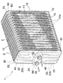
図1、図3〜図5を参照すると、この発明による積層型エバポレータ(1) はアルミニウム(アルミニウム合金を含む)製であって、並列状に配置された多数の中間プレート(2) と、これらの左右両外側に一対ずつ配置された2組のエンドプレート(20)(30)(50)(60)とを備えている。
【0013】
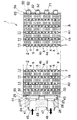
図1、図3〜図5、図7に詳しく示すように、各中間プレート(2) には、これの片面の上端寄り部分に上部タンク形成用凹部(3) が設けられ、中間プレート(2) 片面の下端寄り部分に前後一対の下部タンク形成用凹部(5)(5)が設けられ、中間プレート(2) 片面の高さの中間部分に、側面よりみて逆U形の流体流路形成用凹部(4) が設けられて、該流体流路形成用凹部(4) の2つの端部が下部タンク形成用凹部(5)(5)にそれぞれ連なるものとなされており、各中間プレート(2) の逆U形流体流路形成用凹部(4) の中央部に上下方向に長い仕切用凸条(6) が、同凹部(4) の上端寄り部分から下端部まで設けられている。
【0014】
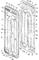
図3と図6を参照すると、左側エンドプレート(20)(30)の組のうちのコア外側の左側第1エンドプレート(20)の対向面に、流体導入流路形成用凹部(22)と、該凹部(22)とは区分された流体排出流路形成用凹部(23)とが設けられ、かつ流体導入流路形成用凹部(22)の底壁(22a) に流体導入孔(24)があけられ、流体排出流路形成用凹部(23)の底壁(23a) に流体排出孔(26)があけられている。
【0015】
同コア内側の左側第2エンドプレート(30)の対向面に、上端部の上部タンク形成用凹部(31)と、これに連なる流体導入流路形成用凹部(32)と、該凹部(32)とは区分された流体排出流路形成用凹部(33)と、これの下端部に連なる下部タンク形成用凹部(34)とが設けられている。
【0016】
なお、図示のものに限らず、左側エンドプレート(20)(30)の組のうちの少なくとも一方のエンドプレートの対向面に、流体導入流路形成用凹部が設けられるとともに、同少なくとも一方のエンドプレートの対向面に、該流体導入流路形成用凹部とは区分された流体排出流路形成用凹部が設けられておれば良く、左側第1エンドプレート(20)に、流体導入流路形成用凹部に連通する流体導入孔(24)と、流体排出流路形成用凹部に連通する流体排出孔(26)とがあけられておれば良い。また、コア内側の左側第2エンドプレート(30)の対向面に、流体導入流路形成用凹部に連なる上部タンク形成用凹部(31)が設けられるとともに、流体排出流路形成用凹部に連なる下部タンク形成用凹部(34)が設けられておれば良い。
【0017】
従って極端な場合には、左側第1エンドプレート(20)が全面フラットで、これに、第2エンドプレート(30)側の流体導入流路形成用凹部(32)に連通する流体導入孔(24)と、同流体排出流路形成用凹部(33)に連通する流体排出孔(26)とがあけられており、他方、左側第2エンドプレート(30)の対向面に、上部タンク形成用凹部(31)、流体導入流路形成用凹部(32)、流体排出流路形成用凹部(33)、および下部タンク形成用凹部(34)が設けられている。
【0018】
また逆に、左側第2エンドプレート(30)が、上部タンク形成用凹部(31)と下部タンク形成用凹部(34)の部分以外は、フラットであり、左側第1エンドプレート(20)の対向面に、流体導入流路形成用凹部(22)と、流体排出流路形成用凹部(23)とが設けられ、かつ流体導入流路形成用凹部(22)の底壁(22a) に流体導入孔(24)があけられ、流体排出流路形成用凹部(23)の底壁(23a) に流体排出孔(26)があけられている。
【0019】
図5と図10を参照すると、右側エンドプレート(50)(60)の組のうちのコア外側の右側第3エンドプレート(50)の対向面に、流体流路形成用凹部(52)が設けられ、同コア内側の右側第4エンドプレート(60)の対向面に、上部タンク形成用凹部(61)と、これに連なる流体流路形成用凹部(62)と、該凹部(62)の下端部に連なる下部タンク形成用凹部(63)とが設けられている。
【0020】
なお、図示のものに限らず、右側エンドプレート(50)(60)の組のうちの少なくとも一方のエンドプレートの対向面に、流体流路形成用凹部が設けられ、コア内側の右側第4エンドプレート(60)の対向面に、流体流路形成用凹部の上端部に連なる上部タンク形成用凹部(61)と、同流体流路形成用凹部の下端部に連なる下部タンク形成用凹部(63)とが設けられておれば良い。
【0021】
従って極端な場合には、右側第3エンドプレート(50)が全面フラットであり、右側第4エンドプレート(60)の対向面に、上部タンク形成用凹部(61)と、流体流路形成用凹部(62)と、下部タンク形成用凹部(63)とが設けられている。
【0022】
また逆に、右側第4エンドプレート(60)が、上部タンク形成用凹部(61)と下部タンク形成用凹部(63)の部分以外は、フラットであり、右側第3エンドプレート(50)の対向面に、流体流路形成用凹部(52)が設けられている。
【0023】
隣り合う中間プレート(2)(2)同士が互いに凹部を対向させた状態に層状に重ね合わせられ、かつ左側エンドプレート(20)(30)の組が互いに凹部を対向させた状態に重ね合わせられるとともに、右側エンドプレート(50)(60)の組が互いに凹部を対向させた状態に重ね合わせられている。
【0024】
隣り合う中間プレート(2)(2)の互いに対向する仕切用凸条(6)(6)同士、および同周縁部(7)(7)同士が接合されることにより、上部タンク部(10)と、側面よりみて逆U形の多数の偏平管部(11)と、各偏平管部(11)の端部に連なる前後両下部タンク部(12a)(12b)とが形成されている(図3参照)。
【0025】
左側エンドプレート(20)(30)の周縁部(25)(25)同士が互いに接合されることにより、上部タンク部(40)と、これに連なる流体導入流路(41)と、流体導入流路(41)とは区分された流体排出流路(43)と、これの下端部に連なる下部タンク部(42)とが形成されている(図4参照)。
【0026】
なお、コア外側の左側第1エンドプレート(20)の中央部には、流体導入孔(24)と流体排出孔(26)とに通じる流体導入部(45)および流体排出部(46)を貫通状に備えた膨脹弁接続用ブロック(44)が取り付けられている。また該ブロック(44)の流体導入部(45)および流体排出部(46)の周縁部において外方に突出した短筒部にそれぞれO−リング(47)(47)が被せ止められている(図4参照)。
【0027】
また、右側エンドプレート(50)(60)の周縁部(55)(65)同士が互いに接合されることにより、上部タンク部(70)と、これに連なる流体流路(71)と、これの下端部に連なる下部タンク部(72)とが形成されている(図5参照)。
【0028】
なお、左側エンドプレート(20)(30)同士の間に設けられた上部タンク部(40)、隣り合う中間プレート(2)(2)同士の間に設けられた上部タンク部(10)、並びに右右側エンドプレート(50)(60)同士の間に設けられた上部タンク部(70)は後述するように、冷媒よりなる流体の導入だけに用いられるので、それらの容積は、左側エンドプレート(20)(30)同士の間の下部タンク部(40)、中間プレート(2)(2)同士の間の下部タンク部(12a)(12b)、並びに右側エンドプレート(50)(60)同士の間の間の下部タンク部(72)の容積の約半分の大きさであれば、良いものである。
【0029】
隣り合う偏平管部(11)(11)同士の間、あるいは左右エンドプレート(30)(60)とこれらに隣り合う同側の偏平管部(11)との間には、コルゲートフィン(18)がそれぞれ介在されている。
【0030】
図4と図7を参照すると、各中間プレート(2) の上部タンク形成用凹部(3) の底壁(3a)に流体通過用孔(13)があけられ、また図5と図7を参照すると、下部タンク形成用凹部(5)(5)の底壁(5a)(5a)にそれぞれ流体通過用孔(15)(15)があけられている。
【0031】
また図4と図6を参照すると、コア内側の左側第3エンドプレート(30)の上部タンク形成用凹部(31)の底壁(31a) に流体通過用孔(36)があけられ、また図5と図6を参照すると、下部タンク形成用凹部(34)の底壁(34a) にそれぞれ流体通過用孔(37)(37)があけられている。
【0032】
さらに図4と図10を参照すると、コア内側の右側第4エンドプレート(60)の上部タンク形成用凹部(61)の底壁(61a) に流体通過用孔(66)があけられ、また図5と図10を参照すると、下部タンク形成用凹部(63)の底壁(63a) に流体通過用孔(67)があけられている。
【0033】
図2と図5を参照すると、積層型エバポレータ(1) の多数の並列状の偏平管部(11)を構成する中間プレート(2) のうち、左右方向中央部の中間プレート(2) の前側下部タンク形成用凹部(5) の底壁(5a)に仕切壁部(17)が設けられていて、コア(A) が、該仕切壁部(17)より右側の右側コア・ユニット(A1)と、同左側の左側コア・ユニット(A2)とに区分されている。
【0034】
図示の実施形態の積層型エバポレータ(1) においては、図3と図7を参照すると、各中間プレート(2) の流体流路形成用凹部(4) の幅中央部に、上下方向に長くかつ中間プレート(2) の周縁部(7) と同じ高さを有する仕切用凸条(6) が、同凹部(4) の下端より上端寄り部分まで設けられている。
【0035】
そして、各中間プレート(2) の流体流路形成用凹部(4) には、仕切用凸条(6) の前後両側において凹部(4) の深さの2倍の高さを有する多数の凸条(8)(9)が、中間プレート(2)(2)の重ね合わせ状態において偏平管部(11)内に独立した並列状の分割流体流路を形成するように、設けられている。
【0036】
すなわち、各凸条(8)(9)は、流体流路形成用凹部(4) の前後両直線流路構成部(4a)(4b)内に設けられた直線部(8a)(9a)、およびこれらに連なりかつ同凹部(4) の折返し部(4c)に設けられた4分の1円弧部(8b)(9b)よりなるU字のちょうど半分の形状を有している。
【0037】
これらの凸条(8)(9)の直線部(8a)(9a)と4分の1円弧部(8b)(9b)とは、隣り合う中間プレート(2)(2)同士が凹部(3)(3)を対向させた重ね合わせ状態において交互に位置するように配せられている。
【0038】
そして、これら両中間プレート(2)(2)の重ね合わせ状態において、相互に対向する仕切用凸条(6)(6)同士および同中間プレート周縁部(7)(7)同士が相互に突き合わせられて接合されるとともに、両凸条(8)(9)の直線部(8a)(9a)および4分の1円弧部(8b)(9b)の先端部が、これらに対向する中間プレート(2) の流体流路形成用凹部(4) の底壁に接合されて、偏平管部(11)の逆U形流体流路内に、相互に連続する凸条(8)(9)によって分割された並列状の逆U形分割流体流路が形成されている。各分割流体流路の折返し部分は半円弧状となっている。
【0039】
各分割流体流路の断面は、偏平管部(11)の逆U形流体流路に液が均等に分布し、しかも偏平管部(11)とコルゲートフィン(18)との接合面積を確保するため、正方形に近い形とされている。また、各分割流体流路の断面積については、内側にあるものが最も大きくなされ、外側にあるものが最も小さくなされ、中間にあるもの同士では、互いに等しいか内側の方が大きくなされている。これにより外側と内側の流速の均一化が図られるのが、好ましい。
【0040】
なお、各中間プレート(2) 下端の前後コーナー部には、中間プレート(2) の周縁部(7)と同じ高さを有する略三角形状の前後補強凸部(19)が設けられている。
【0041】
また、図4と図7を参照すると、各中間プレート(2) の上部タンク形成用凹部(3) の流体通過孔(13)のうち、一方の流体通過孔(13)の周縁部に、バーリング加工により凹部(3) の外側に突出した環状壁部(14)が設けられ、隣り合う偏平管部(11)の対向する中間プレート(2)(2)同士が重なり合わされたさい、上部タンク部(10)において、一方の中間プレート(2) の上部タンク形成用凹部(3) の流体通過孔(13)周縁の環状壁部(14)が、対向する中間プレート(2) の上部タンク形成用凹部(3) の流体通過孔(13) 内に嵌め入れられている。
【0042】
同様に、図5と図7を参照すると、各中間プレート(2) の下部タンク形成用凹部(5) の流体通過孔(15)のうち、一方の流体通過孔(15)の周縁部に、バーリング加工により凹部(5) の外側に突出した環状壁部(16)が設けられ、隣り合う偏平管部(11)の対向する中間プレート(2)(2)同士が重なり合わされたさい、下部タンク部(12a)(12b)において、一方の中間プレート(2) の下部タンク形成用凹部(5) の流体通過孔(15)周縁の環状壁部(16)が、対向する中間プレート(2) の下部タンク形成用凹部(5) の流体通過孔(15)内に嵌め入れられている。
【0043】
また、図8に示す中間プレート(2) には、前側下部タンク形成用凹部(5) の底壁(5a)に仕切壁部(17)が設けられており、該中間プレート(2) は、積層型エバポレータ(1) の左右方向中央部に配置されて、コア(A) を右側コア・ユニット(A1)と左側コア・ユニット(A2)とに二分している(図2と図5参照)。
【0044】
図9に示す中間プレート(2) には、後側下部タンク形成用凹部(5) の底壁(5a)に仕切壁部(17)が設けられており、該中間プレート(2) は、積層型エバポレータ(1) の左端部に配置されて、該仕切壁部(17)は、左側第2エンドプレート(30)の下部タンク形成用凹部(34)の底壁に接合されている(図5参照)。
【0045】
図6参照すると、左側エンドプレート(20)(30)の組のうちのコア外側の左側第1エンドプレート(20)上側の流体導入流路形成用凹部(22)は、上方に向かって4つに分岐した並列状の分岐凹部(22A) と、これらの下端部に連なる連通用凹部(22B) とで構成され、連通用凹部(22B) の底壁(22a) には、流体導入孔(24)があけられるとともに、流体導入孔(24)の周縁部に、バーリング加工により凹部(22)の外側に突出した環状壁部(27)が設けられている。
【0046】
同左側第1エンドプレート(20)下側の流体導入流路形成用凹部(23)は、下方に向かって4つに分岐した並列状の分岐凹部(23A) と、これらの上端部に連なる連通用凹部(23B) とで構成され、連通用凹部(23B) の底壁(23a) には、流体導入孔(26)があけられるとともに、流体導入孔(26)の周縁部に、バーリング加工により凹部(23)の外側に突出した環状壁部(27)が設けられている。
【0047】
これに対し、コア内側の左側第2エンドプレート(30)上側の流体導入流路形成用凹部(32)は、上方に向かって4つに分岐した並列状の分岐凹部(32A) と、これらの下端部に連なる連通用凹部(32B) とで構成されている。そして、この第2エンドプレート(30)の上端部に、4つの分岐凹部(32A) に連なる横長の1つの上部タンク形成用凹部(31)が設けられ、該凹部(31)の底壁(31a) に前後2つの横長の流体通過用孔(36)(36)があけられている。これらのうち、前側の流体通過用孔(36)の周縁部に、バーリング加工により凹部(31)の外側に突出した環状壁部(38)が設けられている。
【0048】
同左側第2エンドプレート(30)下側の流体導入流路形成用凹部(33)は、下方に向かって4つに分岐した並列状の分岐凹部(33A) と、これらの上端部に連なる連通用凹部(33B) とで構成されている。そして、この第2エンドプレート(30)の下端部に、4つの分岐凹部(33A) に連なる1つの下部タンク形成用凹部(34)が設けられ、該凹部(34)の底壁(34a) の前側部に流体通過用孔(37)があけられ、この流体通過用孔(37)の周縁部に、バーリング加工により凹部(34)の外側に突出した環状壁部(39)が設けられている(図5参照)。
【0049】
左側エンドプレート(20)(30)の組が互いに凹部を対向させた状態に重ね合わせられ、かつ隣り合う中間プレート(2)(2)同士が互いに凹部を対向させた状態に層状に重ね合わせられ、さらに、膨脹弁接続用ブロック(44)が、コア外側の左側第1エンドプレート(20)の中央部に取り付けられたさいには、まず左側第1エンドプレート(20)側の流体導入孔(24)周縁部の環状壁部(27)および流体排出孔(26)周縁部の環状壁部(28)が、ブロック(44)の流体導入部(45)および流体排出部(46)のコア内側周縁部に設けられた環状段部にそれぞれ嵌入れられる(図3参照)。
【0050】
また、コア内側の左側第2エンドプレート(30)の上部タンク形成用凹部(31)の底壁(31a) に設けられた前側流体通過用孔(36)周縁の環状壁部(38)は、相互に隣り合う中間プレート(2) の上部タンク形成用凹部(3) の同側の流体通過用孔(13)に嵌め入れられ、他方、後側流体通過用孔(36)には、中間プレート(2) 側の流体通過用孔(13)周縁の環状壁部(14)が嵌め入れられる(図4参照)。
【0051】
さらに、同左側第2エンドプレート(30)の下部タンク形成用凹部(34)の底壁(34a) に設けられた前側流体通過用孔(37)周縁の環状壁部(39)は、相互に隣り合う中間プレート(2) の下部タンク形成用凹部(5) の同側の流体通過用孔(15)に嵌め入れられる(図5参照)。
【0052】
つぎに、図10を参照すると、コア内側の右側第4エンドプレート(60)の上端部に横長の1つの上部タンク形成用凹部(61)が設けられ、該凹部(61)の底壁(61a) に前後2つの横長の流体通過用孔(66)があけられている。これらのうち、後側の流体通過用孔(66)の周縁部に、バーリング加工により凹部(61)の外側に突出した環状壁部(68)が設けられている(図4参照)。
【0053】
同右側第4エンドプレート(60)の下端部に、横長の1つの下部タンク形成用凹部(63)が設けられ、該凹部(63)の底壁(63a) の前側部に流体通過用孔(67)があけられている(図5参照)。
【0054】
そして、右側エンドプレート(50)(60)の組が互いに凹部を対向させた状態に重ね合わせられ、かつ隣り合う中間プレート(2)(2)同士が互いに凹部を対向させた状態に層状に重ね合わせられたさいには、右側第4エンドプレート(60)の上部タンク形成用凹部(61)の底壁(61a) に設けられた後側流体通過用孔(66)周縁の環状壁部(68)は、相互に隣り合う中間プレート(2) の上部タンク形成用凹部(3) の同側の流体通過用孔(13)に嵌め入れられる(図5参照)、他方、前側流体通過用孔(66)には、中間プレート(2) の流体通過用孔(13)周縁の環状壁部(14)が嵌め入れられる(図4参照)。
【0055】
さらに、同右側第4エンドプレート(60)の下部タンク形成用凹部(63)の底壁(63a) に設けられた前側流体通過用孔(67)周縁の環状壁部(68)は、相互に隣り合う中間プレート(2) の下部タンク形成用凹部(5) の同側の流体通過用孔(15)周縁の環状壁部(14)が嵌め入れられる(図5参照)
上記積層型エバポレータ(1) においては、その構成部材のうち、中間プレート(2) 、左側エンドプレート(20)(30)、および右側エンドプレート(50)(60)がアルミニウム・ブレージング・シートによりつくられており、コルゲートフィン(18)および膨脹弁接続用ブロック(44)がアルミニウム製である。
【0056】
そして、上記積層型エバポレータ(1) のすべての構成部材が組み合わせられた状態で、例えば真空ろう付け法により一括してろう付けされることにより、製造されるものである。
【0057】
図2を参照すると、積層型エバポレータ(1) 全体の流体流路は、つぎの通りである。
【0058】
すなわち、冷媒よりなる流体は、左側第1エンドプレート(20)の流体導入孔(24)を経て左側エンドプレート(20)(30)の組の流体導入流路(41)内に導入され、さらに流体は、左側エンドプレート(20)(30)の組の上部タンク部(40)、および多数の中間プレート(2)(2)の組の上部タンク部(10)を経て、右側エンドプレート(50)(60)の組の上部タンク部(70)に至る。
【0059】
そこから流体は、該上部タンク部(70)より右側エンドプレート(50)(60)の組の流体流路(71)および下部タンク部(72)を経て、右側コア・ユニット(A1)の多数の中間プレート(2)(2)の組の一方の前側下部タンク部(12a) より逆U形偏平管部(11)の同側端部に流入し、該偏平管部(11)内を前から後に逆U状に流れた後、他方の後側下部タンク部(12b) より流れ出て、左側コア・ユニット(A2)の後側下部タンク部(12b) に至る。
【0060】
さらに流体は、左側コア・ユニット(A2)の後側下部タンク部(12b) より逆U形偏平管部(11)の同側端部に流入し、該偏平管部(11)内を今度は後から前に逆U状に流れた後、前側下部タンク部(12a) より流れ出て、左側エンドプレート(20)(30)の組の下部タンク部(42)に至る。
【0061】
そして最後に、流体は、左側エンドプレート(20)(30)の組の流体排出流路(43)から流体排出孔(26)を経て、外部に流出されるものである。
【0062】
一方、空気は、前方から後方に向かって流されて、積層型エバポレータ(1) の隣り合う偏平管部(11)(11)同士の間、偏平管部(11)と左側第2エンドプレート(30)との間、あるいは偏平管部(11)と右側第4エンドプレート(70)との間のコルゲートフィン(18)の存在する間隙を通過し、中間プレート(2) 、左側第2エンドプレート(30)、および右側第4エンドプレート(70)の壁面、およびコルゲート・フィン(18)を介して流体と空気とが効率よく熱交換せられるものである。
【0063】
なお、図示の実施形態の積層型エバポレータ(1) によれば、各偏平管部(11)の逆U形流体流路内を流体が流れるとき、流体は隣り合う分割流体流路間では混ざりあうことはなく、かつ流体の流れに滞留部を生じることなく、偏平管部(11)内を流れる。従って、気液分離は1つの分割流体流路内だけにとどまるため小さくなり、流体の圧力損失の上昇を招くことがない。特に、ターン部分での流体の流れがスムーズとなり、熱伝達率の向上を果たし得る。また逆U形偏平管部(11)のターン部分の前後において流体の流れによどみや偏流が生じることなく、流体にわずかに混入されているオイルの溜りも防止され、また、流体と外気との平均温度の差が小さくなり、より一層熱伝達率が向上する。
【0064】
なお、各中間プレート(2) に設けられる凸条(8)(9)の形状は、図示のものに限定されず、隣り合う中間プレート(2)(2)同士が重ね合わせられたさいに、並列状の逆U形分割流体流路が形成されるものであれば、種々の変更が可能である。
【0065】
また中間プレート(2) では、凸条(8)(9)が、隣り合う中間プレート(2)(2)の重ね合わせ状態において互い違いに位置するように設けられるとともに、両中間プレート(2)(2)の重ね合わせ後に、偏平管部(11)の逆U形流体流路において両凸条(8)(9)により全体として逆U形となるように、前後に対称に配置されているから、各中間プレート(2) に設ける凸条(8)(9)の数が少なくてすみ、従って各中間プレート(2) の形状が簡単で、その成形が容易であり、かつ製造コストを低減し得るものである。
【0066】
また、各中間プレート(2) の逆U形流体流路形成用凹部(4) の凸条(8)(9)の先端部が、それぞれ対向する中間プレート(2) の凹部(4) の底壁(18)に接合されているから、接合面積が大きくなり、いわゆる点接触とならず、線接触によって接合されるので、耐圧強度が増大する。
【0067】
なお、図示の実施形態の積層型エバポレータ(1) においては、左側エンドプレート(20)(30)の組のうちのコア外側の左側第1エンドプレート(20)の対向面に設けられた流体導入流路形成用凹部(22)と流体排出流路形成用凹部(23)とが、互いに略同じ大きさに形成されているが、これらの凹部(22)(23)は、いずれか一方が小さく、他方が大きいものとなされていても良い。
【0068】
なお、図示のものは、積層型エバポレータ(1) のコア(A) が、左右方向中央部の中間プレート(2) の下部タンク形成用凹部(5) の底壁(5a)前半部に設けられた仕切壁部(17)によって二分されているが、このような仕切壁部(17)を設ける位置は、左右各端より丁度2分の1のところに限られるものではなく、熱交換性能を考慮して適宜左右にずらされる。また場合によっては、このような仕切壁部(17)を設けることなく、コア(A) を1つのものとすることができるし、あるいはまたこのような仕切壁部(17)を2つ以上設けることにより、積層型エバポレータ(1) のコア(A) を3以上に区分するようにしても良い。
【0069】
また、図示のものは、各中間プレート(2) に凸条(8)(9)が設けられて、隣り合う中間プレート(2)(2)同士の間に並列状の逆U形分割流体流路が形成されているが、中間プレート(2) にこのような凸条を設けることなく、中間プレート(2)(2)同士の間に例えばマルチエントリー・フィンなどのインナーフィン(図示略)を挿入して、流体流路を形成するようにしても良く、偏平管部(11)内の流体流路の形成については種々の変更が可能である。
【0070】
また、積層型エバポレータ(1) の上下および左右は、図示のものと逆であっても良く、従って、流体導入側の左側エンドプレート(20)(30)の組の上部タンク部(40)、多数の中間プレート(2)(2)の組の上部タンク(10)、および右側エンドプレート(50)(60)の組の上部タンク部(70)が下側に配置されるようになされていても良い。
【0071】
【発明の効果】
この発明の積層型熱交換器は、上述のように、並列状に配置された多数の中間プレートと、これらの左右両外側に一対ずつ配置された2組のエンドプレートとを備え、各中間プレートの片面の上端寄り部分に上部タンク形成用凹部が設けられ、中間プレート片面の下端寄り部分に前後一対の下部タンク形成用凹部が設けられ、中間プレート片面の高さの中間部分に、側面よりみて逆U形の流体流路形成用凹部が設けられて、該流体流路形成用凹部の2つの端部が下部タンク形成用凹部にそれぞれ連なるものとなされており、各中間プレートの逆U形流体流路形成用凹部の中央部に上下方向に長い仕切用凸条が、同凹部の上端寄り部分から下端部まで設けられ、左側エンドプレートの組のうちの少なくとも一方のエンドプレートの対向面に、流体導入流路形成用凹部が設けられるとともに、同少なくとも一方のエンドプレートの対向面に、該流体導入流路形成用凹部とは区分された流体排出流路形成用凹部が設けられ、左側第1エンドプレートに、流体導入流路形成用凹部に連通する流体導入孔と、流体排出流路形成用凹部に連通する流体排出孔とがあけられ、コア内側の左側第2エンドプレートの対向面に、流体導入流路形成用凹部に連なる上部タンク形成用凹部が設けられるとともに、流体排出流路形成用凹部に連なる下部タンク形成用凹部が設けられ、右側エンドプレートの組のうちの少なくとも一方のエンドプレートの対向面に、流体流路形成用凹部が設けられ、コア内側の右側第4エンドプレートの対向面に、流体流路形成用凹部の上端部に連なる上部タンク形成用凹部と、同流体流路形成用凹部の下端部に連なる下部タンク形成用凹部とが設けられており、隣り合う中間プレート同士が互いに凹部を対向させた状態に層状に重ね合わせられ、かつ左側エンドプレートの組が互いに凹部を対向させた状態に重ね合わせられるとともに、右側エンドプレートの組が互いに凹部を対向させた状態に重ね合わせられ、隣り合う中間プレートの互いに対向する仕切用凸条同士、および同周縁部同士が接合されることにより、上部タンク部と、側面よりみて逆U形の多数の偏平管部と、各偏平管部の端部に連なる下部タンク部とが形成され、左側エンドプレートの周縁部同士が互いに接合されることにより、上部タンク部と、これに連なる流体導入流路と、流体導入流路とは区分された流体排出流路と、これの下端部に連なる下部タンク部とが形成され、右側エンドプレートの周縁部同士が互いに接合されることにより、上部タンク部と、これに連なる流体流路と、これの下端部に連なる下部タンク部とが形成され、各中間プレートの上部タンク形成用凹部の底壁に流体通過用孔があけられ、かつ下部タンク形成用凹部の底壁にそれぞれ流体通過用孔があけられ、コア内側の左側エンドプレートの上部タンク形成用凹部の底壁に流体通過用孔があけられ、かつ下部タンク形成用凹部の底壁にそれぞれ流体通過用孔があけられ、コア内側の右側エンドプレートの上部タンク形成用凹部の底壁に流体通過用孔があけられ、かつ下部タンク形成用凹部の底壁に流体通過用孔があけられており、左側エンドプレートの流体導入孔から左側エンドプレートの組の流体導入流路内に導入された流体が、左側エンドプレートの組の上部タンク部、および多数の中間プレートの組の上部タンク部を経て、右側エンドプレートの組の上部タンク部に至り、さらに流体は、該上部タンク部より右側エンドプレートの組の流体流路および下部タンク部を経て、多数の中間プレートの組の一方の下部タンク部より逆U形偏平管部の同側端部に流入し、該偏平管部内を逆U状に流れた後、他方の下部タンク部より流れ出て、左側エンドプレートの組の下部タンク部に至り、最後に左側エンドプレートの組の流体排出流路から流体排出孔を経て、外部に流出するようになされているもので、この発明の積層型熱交換器によれば、エンドプレート部分に流体導入流路および同排出流路を一体に設けることにより、従来の出入口パイプの取付け工程を省略し、部品点数を減少することができて、加工工数の削減を図ることができ、ひいては製造コストを低減し得る。また出入口パイプの取付けを省略した分、熱交換器の外形が小さくなり、該熱交換器を収納するためのクーリングケースのコンパクト化を果たし得るものである。
【0072】
また、左側エンドプレート同士の間に設けられた上部タンク部、隣り合う中間プレート同士の間に設けられた上部タンク部、並びに右側エンドプレート同士の間に設けられた上部タンク部は、冷媒よりなる流体の導入だけに用いられるので、それらの容積は、左側エンドプレート同士の間に設けられた下部タンク部、隣り合う中間プレート同士の間に設けられた下部タンク部、並びに右側エンドプレート同士の間に設けられた下部タンク部の容積の例えば半分の大きさであれば良く、従って両タンク式の積層型エバポレータの有効コア面積を充分に確保することができるという効果を奏する。
【図面の簡単な説明】
【図1】本発明品の概略斜視図である。
【図2】同本発明品の流体流路の説明をするための概略斜視図である。
【図3】同本発明品の中央部の水平断面である。
【図4】同本発明品の上部タンク部分の水平断面である。
【図5】同本発明品の下部タンク部分の水平断面である。
【図6】左側エンドプレートの組を示す斜視図である。
【図7】中間プレートの組を示す斜視図である。
【図8】仕切壁部を有する中間プレートの一例を示す斜視図である。
【図9】仕切壁部を有する中間プレートのいま1つの例を示す斜視図である。
【図10】右側エンドプレートの組を示す斜視図である。
【符号の説明】
1 積層型エバポレータ(積層型熱交換器)
2 中間プレート
3 上部タンク形成用凹部
3a 底壁
4 逆U形の流体流路形成用凹部
5 下部タンク形成用凹部
5a 底壁
6 長い仕切用凸条
7 周縁部
10 上部タンク部
11 側面よりみて逆U形の偏平管部
12a 前側下部タンク部
12b 後側下部タンク部
13 流体通過用孔
15 流体通過用孔
20 左側第1エンドプレート
22 流体導入流路形成用凹部
22a 底壁
23 流体排出流路形成用凹部
23a 底壁
24 流体導入孔
25 周縁部
26 流体排出孔
30 左側第2エンドプレート
31 上部タンク形成用凹部
31a 底壁
32 流体導入流路形成用凹部
33 流体排出流路形成用凹部
34 下部タンク形成用凹部
34a 底壁
36 流体通過用孔
37 流体通過用孔
40 上部タンク部
41 流体導入流路
42 下部タンク部
43 流体排出流路
50 右側第3エンドプレート
52 流体流路形成用凹部
55 周縁部
60 右側第4エンドプレート
61 上部タンク形成用凹部
61a 底壁
62 流体流路形成用凹部
63 下部タンク形成用凹部
63a 底壁
65 周縁部
66 流体通過用孔
67 流体通過用孔
70 上部タンク部
71 流体流路
72 下部タンク部[0001]
BACKGROUND OF THE INVENTION
The present invention relates to a stacked heat exchanger used for an evaporator for a car / air conditioner or the like.
[0002]
[Prior art]
Conventionally, this type of laminated evaporator has a tank on the end plate in both the tank type with the tank part provided on the upper and lower sides of the laminated plate and the single tank type with the tank part provided on one side. By joining the header part connected to the part and attaching the inlet / outlet pipe to the header part, the refrigerant introduction / discharge path is formed.
[0003]
[Problems to be solved by the invention]
However, in this case, in the cooling case for storing the evaporator, it is necessary to secure a space for the inlet / outlet pipe, the outer shape becomes large, and a separate process for joining the inlet / outlet pipe to the header portion is required, which is troublesome. There was a problem. In addition, if the inlet / outlet pipe and the header part are integrated and brazed together in the furnace, the process can be eliminated, but so-called furnace charging efficiency deteriorates, and there has been a sway that there is no change in the total cost. .
[0004]
Recently, an evaporator having a structure in which an inlet / outlet portion is gathered in one end plate has been proposed (see, for example, JP-A-7-294160 and JP-A-7-270089).
[0005]
However, with this conventional evaporator structure, there is a problem that the resistance increases because three tank portions are concentrated on one side.
[0006]
In both tank type evaporators, since the refrigerant usually expands in volume inside the evaporator, it is necessary to increase the size of the tank part to some extent, and the effective core area in the evaporator body is reduced accordingly. There was a problem.
[0007]
The object of the present invention is to solve the above-mentioned problems of the prior art, and by providing the fluid introduction flow path and the discharge flow path integrally in the end plate portion, the conventional process of attaching the inlet / outlet pipe is omitted, and the number of parts is reduced. The number of processing steps can be reduced, the manufacturing cost can be reduced, and the cooling case can be made compact. In addition, the effective core area can be sufficiently increased in the double tank type stacked evaporator. An object of the present invention is to provide a stacked heat exchanger that can be secured.
[0008]
[Means for Solving the Problems]
In order to achieve the above object, a laminated heat exchanger according to the present invention includes a large number of intermediate plates arranged in parallel and two sets of end plates arranged in pairs on the left and right outer sides. An upper tank forming recess is provided near the upper end of one side of each intermediate plate, and a pair of front and rear lower tank forming recesses are provided near the lower end of the intermediate plate one side. In addition, a reverse U-shaped fluid flow path forming recess is provided when viewed from the side, and two end portions of the fluid flow path forming recess are respectively connected to the lower tank forming recess. At the center of the concave part for forming the inverted U-shaped fluid flow path, a vertically extending partitioning ridge is provided from the upper end portion to the lower end part of the concave part, and at least one end plate of the set of left end plates. A recess for forming a fluid introduction channel is provided on the opposite surface of the fluid discharge channel, and a recess for forming a fluid discharge channel that is separated from the recess for forming the fluid introduction channel is provided on the opposite surface of at least one end plate. The left first end plate is provided with a fluid introduction hole communicating with the fluid introduction passage forming recess and a fluid discharge hole communicating with the fluid discharge passage formation recess, and the left second end on the inner side of the core. On the opposite surface of the plate, an upper tank forming recess connected to the fluid introduction flow path forming recess and a lower tank forming recess connected to the fluid discharge flow path forming recess are provided. A fluid flow path forming recess is provided on the facing surface of at least one of the end plates, and an upper surface continuous with the upper end of the fluid flow path forming recess is formed on the facing surface of the right fourth end plate inside the core. A recess for forming a tank and a recess for forming a lower tank connected to a lower end of the recess for forming a fluid flow path, and adjacent intermediate plates are layered in a state where the recesses face each other, In addition, the left end plate set is overlaid with the recesses facing each other, and the right end plate set is overlaid with the recesses facing each other, so that the adjacent intermediate plates face each other. By joining each other and the same peripheral edge portion, an upper tank portion, a number of inverted U-shaped flat tube portions viewed from the side surface, and a lower tank portion connected to the end of each flat tube portion are formed, By joining the peripheral edge portions of the left end plate to each other, the upper tank portion, the fluid introduction flow channel connected to the upper tank portion, and the fluid discharge flow channel separated from the fluid introduction flow channel are provided. And a lower tank portion connected to the lower end portion of the right end plate is joined to each other to form an upper tank portion, a fluid flow passage connected to the upper tank portion, and a lower tank connected to the lower end portion thereof. And a fluid passage hole is formed in the bottom wall of the upper tank formation recess of each intermediate plate, and a fluid passage hole is formed in each bottom wall of the lower tank formation recess, and the left side inside the core. A fluid passage hole is made in the bottom wall of the upper tank forming recess of the end plate, and a fluid passage hole is made in the bottom wall of the lower tank formation recess to form the upper tank of the right end plate inside the core. A fluid passage hole is formed in the bottom wall of the recess, and a fluid passage hole is formed in the bottom wall of the recess for forming the lower tank. The fluid introduced into the fluid introduction flow path passes through the upper tank portion of the left end plate set and the upper tank portion of the multiple intermediate plate sets to the upper tank portion of the right end plate set, and The fluid flows from the upper tank part through the fluid flow path and the lower tank part of the right end plate set to the same side end of the inverted U-shaped flat tube part from one of the lower tank parts of the set of intermediate plates. Then, after flowing in an inverted U shape in the flat tube portion, it flows out from the other lower tank portion, reaches the lower tank portion of the left end plate set, and finally flows from the fluid discharge passage of the left end plate set. It is characterized by flowing out to the outside through the discharge hole.
[0009]
DETAILED DESCRIPTION OF THE INVENTION
Next, an embodiment of the present invention will be described with reference to the drawings.
[0010]
In this specification, front and rear, left and right, and top and bottom are based on FIG. 3, the left is the left side of FIG. 3, the right is the same right side, the front is the lower side of the figure, and the rear is the same upper side. The upper side means the front side of the drawing sheet and the lower side means the back side.
[0011]
The drawings show the case where the present invention is applied to a laminated evaporator for a car air conditioner.
[0012]
Referring to FIGS. 1 and 3 to 5, the laminated evaporator (1) according to the present invention is made of aluminum (including an aluminum alloy), and includes a number of intermediate plates (2) arranged in parallel, And two sets of end plates (20), (30), (50), and (60) arranged in pairs on the left and right outer sides.
[0013]
As shown in detail in FIGS. 1, 3 to 5, and 7, each intermediate plate (2) is provided with an upper tank forming recess (3) near the upper end of one side of the intermediate plate (2). ) A pair of front and rear lower tank forming recesses (5) and (5) are provided near the lower end of one side, and an intermediate plate (2) forms an inverted U-shaped fluid flow path in the middle of one side as viewed from the side. Recesses (4) are provided, and two end portions of the fluid flow path forming recesses (4) are connected to the lower tank forming recesses (5) and (5), respectively. In the center portion of the inverted U-shaped fluid flow path forming recess (4) of 2), a vertically extending partitioning ridge (6) is provided from the upper end portion to the lower end of the recess (4).
[0014]
Referring to FIGS. 3 and 6, a fluid introduction flow path forming recess (22) is formed on the opposing surface of the left first end plate (20) outside the core of the set of left end plates (20) and (30). A fluid discharge channel forming recess (23) separated from the recess (22), and a fluid introduction hole (24) in the bottom wall (22a) of the fluid introduction channel forming recess (22). A fluid discharge hole (26) is formed in the bottom wall (23a) of the fluid discharge channel forming recess (23).
[0015]
On the opposing surface of the left second end plate (30) inside the core, there is an upper tank forming recess (31) at the upper end, a fluid introduction flow path forming recess (32) connected to the upper tank forming recess, and the recess (32). Are provided with a fluid discharge channel forming recess (33) and a lower tank forming recess (34) connected to the lower end thereof.
[0016]
Not only the illustrated one but also a recess for forming a fluid introduction channel is provided on the opposing surface of at least one end plate of the left end plate (20) (30), and at least one end of the same is provided. It suffices if a concave portion for forming a fluid discharge channel that is separated from the concave portion for forming a fluid introduction channel is provided on the opposing surface of the plate, and the first end plate (20) on the left side is provided with a fluid introduction channel. It is only necessary that the fluid introduction hole (24) communicating with the recess and the fluid discharge hole (26) communicating with the fluid discharge channel forming recess are formed. Further, an upper tank forming recess (31) connected to the fluid introduction flow path forming recess is provided on the facing surface of the left second end plate (30) inside the core, and a lower part connected to the fluid discharge flow path forming recess. A tank forming recess (34) may be provided.
[0017]
Therefore, in an extreme case, the left first end plate (20) is flat on the entire surface, and the fluid introduction hole (24) communicated with the fluid introduction flow path forming recess (32) on the second end plate (30) side. ) And a fluid discharge hole (26) communicating with the fluid discharge channel forming recess (33), on the other hand, an upper tank forming recess on the opposite surface of the left second end plate (30). (31), a fluid introduction channel formation recess (32), a fluid discharge channel formation recess (33), and a lower tank formation recess (34) are provided.
[0018]
Conversely, the second left end plate (30) is flat except for the upper tank forming recess (31) and the lower tank forming recess (34), and is opposed to the left first end plate (20). The surface is provided with a fluid introduction channel forming recess (22) and a fluid discharge channel formation recess (23), and fluid is introduced into the bottom wall (22a) of the fluid introduction channel formation recess (22). A hole (24) is formed, and a fluid discharge hole (26) is formed in the bottom wall (23a) of the fluid discharge channel forming recess (23).
[0019]
Referring to FIGS. 5 and 10, a fluid flow path forming recess (52) is provided on the opposing surface of the right third end plate (50) outside the core of the set of right end plates (50) and (60). The upper tank forming recess (61), the fluid flow path forming recess (62), and the lower end of the recess (62) are formed on the opposite surface of the right fourth end plate (60) inside the core. And a lower tank forming recess (63) that is continuous with the portion.
[0020]
Note that, not limited to the illustrated one, a fluid flow path forming recess is provided on the opposing surface of at least one of the pair of right end plates (50) and (60), and the right fourth end on the inner side of the core. On the opposing surface of the plate (60), an upper tank forming recess (61) connected to the upper end of the fluid flow path forming recess and a lower tank forming recess (63) connected to the lower end of the fluid flow path forming recess And should be provided.
[0021]
Therefore, in extreme cases, the right third end plate (50) is flat on the entire surface, and the upper tank forming recess (61) and the fluid flow path forming recess are formed on the opposite surface of the right fourth end plate (60). (62) and a lower tank forming recess (63) are provided.
[0022]
Conversely, the right side fourth end plate (60) is flat except for the upper tank forming recess (61) and the lower tank forming recess (63), and is opposed to the right third end plate (50). On the surface, a fluid flow path forming recess (52) is provided.
[0023]
Adjacent intermediate plates (2) and (2) are stacked in layers with the recesses facing each other, and the pair of left end plates (20) and (30) are stacked with the recesses facing each other At the same time, the pair of right end plates (50) and (60) are superposed with the concave portions facing each other.
[0024]
The upper tank portion (10) is formed by joining the protruding protrusions (6), (6) facing each other and the peripheral edge portions (7), (7) of the adjacent intermediate plates (2), (2). And a number of inverted U-shaped flat tube portions (11) as viewed from the side, and front and rear lower tank portions (12a) and (12b) connected to the ends of the flat tube portions (11) (see FIG. 3).
[0025]
The peripheral portions (25) and (25) of the left end plates (20) and (30) are joined to each other, so that the upper tank portion (40), the fluid introduction flow path (41) connected thereto, and the fluid introduction flow A fluid discharge passage (43) separated from the passage (41) and a lower tank portion (42) connected to the lower end portion thereof are formed (see FIG. 4).
[0026]
The central part of the left first end plate (20) outside the core penetrates the fluid introduction part (45) and the fluid discharge part (46) communicating with the fluid introduction hole (24) and the fluid discharge hole (26). An expansion valve connecting block (44) provided in a shape is attached. In addition, O-rings (47) and (47) are respectively attached to the short cylindrical portions protruding outward at the peripheral portions of the fluid introduction portion (45) and the fluid discharge portion (46) of the block (44) ( (See FIG. 4).
[0027]
Further, by joining the peripheral edge portions (55) (65) of the right end plates (50) (60) to each other, the upper tank portion (70), the fluid flow path (71) connected thereto, and the A lower tank part (72) connected to the lower end part is formed (see FIG. 5).
[0028]
The upper tank part (40) provided between the left end plates (20) (30), the upper tank part (10) provided between the adjacent intermediate plates (2) (2), and Since the upper tank part (70) provided between the right and right end plates (50) and (60) is used only for the introduction of a fluid made of a refrigerant, as described later, their volume is determined by the left end plate ( 20) between the lower tank part (40) between (30), the lower tank part (12a) (12b) between the intermediate plates (2) (2), and between the right end plates (50) (60) If the size of the lower tank part (72) in between is about half the volume, it is good.
[0029]
Corrugated fins (18) between the adjacent flat tube portions (11) (11) or between the left and right end plates (30) (60) and the flat tube portion (11) on the same side adjacent to these. Are intervened.
[0030]
4 and 7, a fluid passage hole (13) is formed in the bottom wall (3 a) of the upper tank forming recess (3) of each intermediate plate (2). See also FIGS. 5 and 7. Then, fluid passage holes (15) and (15) are formed in the bottom walls (5a) and (5a) of the lower tank forming recesses (5) and (5), respectively.
[0031]
4 and 6, a fluid passage hole (36) is formed in the bottom wall (31a) of the upper tank forming recess (31) of the left third end plate (30) inside the core. 5 and FIG. 6, fluid passage holes (37) and (37) are formed in the bottom wall (34a) of the lower tank forming recess (34), respectively.
[0032]
4 and 10, a fluid passage hole (66) is formed in the bottom wall (61a) of the upper tank forming recess (61) of the right fourth end plate (60) inside the core. 5 and FIG. 10, a fluid passage hole (67) is formed in the bottom wall (63a) of the lower tank forming recess (63).
[0033]
2 and 5, the front side of the intermediate plate (2) at the center in the left-right direction among the intermediate plates (2) constituting the multiple parallel flat tubes (11) of the laminated evaporator (1). A partition wall (17) is provided on the bottom wall (5a) of the lower tank forming recess (5), and the core (A) is located on the right core unit (A1) on the right side of the partition wall (17). And the left core unit (A2) on the left side.
[0034]
In the laminated evaporator (1) of the illustrated embodiment, referring to FIG. 3 and FIG. 7, the middle plate (2) of each intermediate plate (2) is long in the vertical direction at the center of the width and A partition projection (6) having the same height as the peripheral edge (7) of the intermediate plate (2) is provided from the lower end of the recess (4) to the upper end portion.
[0035]
In the fluid flow path forming recesses (4) of each intermediate plate (2), a number of protrusions having a height twice the depth of the recesses (4) on both front and rear sides of the partitioning protrusions (6). The strips (8) and (9) are provided so as to form independent and parallel divided fluid flow paths in the flat tube portion (11) when the intermediate plates (2) and (2) are overlapped.
[0036]
That is, each ridge (8) (9) is a straight portion (8a) (9a) provided in both the front and rear linear flow path components (4a) (4b) of the fluid flow path forming recess (4), Further, it has a shape that is exactly half of a U-shape consisting of quarter arc portions (8b) and (9b) that are connected to these and are provided in the folded portion (4c) of the concave portion (4).
[0037]
The straight portions (8a) and (9a) of these ridges (8) and (9) and the quarter arc portions (8b) and (9b) are formed such that adjacent intermediate plates (2) and (2) are recessed (3 ) And (3) are arranged so as to be alternately positioned in the opposed state.
[0038]
Then, in the state where these two intermediate plates (2) and (2) are overlapped, the partitioning ridges (6) and (6) facing each other and the peripheral edge portions (7) and (7) of the intermediate plate are abutted with each other. And the end portions of the straight portions (8a) (9a) of the two ridges (8) (9) and the quarter arc portions (8b) (9b) are opposed to the intermediate plate ( 2) Connected to the bottom wall of the fluid flow path forming recess (4) and divided into the inverted U-shaped fluid flow path of the flat tube section (11) by the continuous ridges (8) and (9) The parallel inverted U-shaped divided fluid flow paths are formed. The folded portion of each divided fluid flow path has a semicircular arc shape.
[0039]
The cross section of each divided fluid flow path ensures that the liquid is evenly distributed in the inverted U-shaped fluid flow path of the flat tube portion (11) and that the joint area between the flat tube portion (11) and the corrugated fin (18) is secured. Therefore, the shape is close to a square. Moreover, about the cross-sectional area of each division | segmentation fluid flow path, what is inside is made the largest, what is outside is made the smallest, and what is in the middle is made mutually equal or larger inside. It is preferable that the outer and inner flow velocities are thereby made uniform.
[0040]
Note that front and rear corners at the lower end of each intermediate plate (2) are provided with substantially triangular front and rear reinforcing protrusions (19) having the same height as the peripheral edge (7) of the intermediate plate (2).
[0041]
4 and 7, a burring is formed on the periphery of one fluid passage hole (13) of the fluid passage holes (13) of the upper tank forming recess (3) of each intermediate plate (2). When the annular wall (14) projecting outside the recess (3) is provided by processing and the opposed intermediate plates (2) (2) of the adjacent flat tube portions (11) are overlapped, the upper tank portion In (10), the annular wall portion (14) at the periphery of the fluid passage hole (13) of the recess (3) for forming the upper tank of one intermediate plate (2) is used for forming the upper tank of the opposed intermediate plate (2). The recess (3) is fitted into the fluid passage hole (13).
[0042]
Similarly, referring to FIG. 5 and FIG. 7, among the fluid passage holes (15) of the lower tank forming recess (5) of each intermediate plate (2), the peripheral edge portion of one fluid passage hole (15) An annular wall (16) projecting outside the recess (5) is provided by burring and the opposed intermediate plates (2) and (2) of the adjacent flat tube (11) are overlapped with each other. In the parts (12a) and (12b), the annular wall (16) around the fluid passage hole (15) of the lower tank forming recess (5) of one intermediate plate (2) is connected to the opposite intermediate plate (2). The lower tank forming recess (5) is fitted into the fluid passage hole (15).
[0043]
Further, the intermediate plate (2) shown in FIG. 8 is provided with a partition wall portion (17) on the bottom wall (5a) of the front lower tank forming recess (5). Located in the center of the laminated evaporator (1) in the horizontal direction, the core (A) is divided into a right core unit (A1) and a left core unit (A2) (see FIGS. 2 and 5). .
[0044]
The intermediate plate (2) shown in FIG. 9 is provided with a partition wall (17) on the bottom wall (5a) of the rear lower tank forming recess (5). Disposed at the left end of the mold evaporator (1), the partition wall (17) is joined to the bottom wall of the lower tank forming recess (34) of the left second end plate (30) (FIG. 5). reference).
[0045]
Referring to FIG. 6, the fluid introduction flow path forming recesses (22) on the upper left first end plate (20) outside the core of the set of left end plates (20) and (30) are four upward. The parallel branch recesses (22A) branched to the lower end portions and the communication recesses (22B) connected to the lower end portions thereof are formed on the bottom wall (22a) of the communication recesses (22B). ) And an annular wall portion (27) protruding outward from the recess (22) by burring is provided at the peripheral portion of the fluid introduction hole (24).
[0046]
The fluid introduction flow path forming recess (23) below the first end plate (20) on the left side includes a parallel branch recess (23A) branched into four downwards, and a continuous connection to these upper ends. The fluid introduction hole (26) is formed in the bottom wall (23a) of the communication recess (23B) and the peripheral edge of the fluid introduction hole (26) is formed by burring. An annular wall portion (27) protruding outside the recess (23) is provided.
[0047]
On the other hand, the fluid introduction flow path forming recess (32) on the left second end plate (30) on the inner side of the core has a parallel branch recess (32A) branched into four upwards, and these It is comprised by the communication recessed part (32B) connected to a lower end part. The upper end of the second end plate (30) is provided with one horizontally long upper tank forming recess (31) connected to the four branch recesses (32A), and the bottom wall (31a) of the recess (31) is provided. ) Are provided with two horizontally long fluid passage holes (36) and (36). Among these, an annular wall portion (38) protruding outside the recess (31) by burring is provided at the peripheral portion of the front fluid passage hole (36).
[0048]
The fluid introduction flow path forming recess (33) below the second end plate (30) on the left side includes a parallel branch recess (33A) branched into four downwards, and a continuous connection to the upper ends thereof. It consists of a general recess (33B). A lower tank forming recess (34) connected to the four branch recesses (33A) is provided at the lower end of the second end plate (30), and the bottom wall (34a) of the recess (34) A fluid passage hole (37) is formed in the front side portion, and an annular wall portion (39) protruding outside the concave portion (34) by a burring process is provided on a peripheral portion of the fluid passage hole (37). (See FIG. 5).
[0049]
The pair of left end plates (20) and (30) are stacked with the recesses facing each other, and the adjacent intermediate plates (2) and (2) are stacked in layers with the recesses facing each other. Furthermore, when the expansion valve connecting block (44) is attached to the center of the left first end plate (20) outside the core, first, the fluid introduction hole (on the left first end plate (20) side) 24) The annular wall portion (27) at the peripheral edge and the fluid discharge hole (26) the annular wall portion (28) at the peripheral edge are located inside the core of the fluid introduction portion (45) and the fluid discharge portion (46) of the block (44). Each is fitted into an annular step provided on the peripheral edge (see FIG. 3).
[0050]
Further, the annular wall portion (38) around the front fluid passage hole (36) provided in the bottom wall (31a) of the upper tank forming recess (31) of the left second end plate (30) inside the core is: The intermediate plate (2) adjacent to each other is fitted into the fluid passage hole (13) on the same side of the upper tank forming recess (3), while the rear fluid passage hole (36) is inserted into the intermediate plate. (2) The annular wall portion (14) at the periphery of the fluid passage hole (13) on the side is fitted (see FIG. 4).
[0051]
Further, the annular wall portion (39) around the front fluid passage hole (37) provided in the bottom wall (34a) of the lower tank forming recess (34) of the second end plate (30) on the left side is mutually It fits in the fluid passage hole (15) on the same side of the lower tank forming recess (5) of the adjacent intermediate plate (2) (see FIG. 5).
[0052]
Next, referring to FIG. 10, a horizontally long upper tank forming recess (61) is provided at the upper end of the right fourth end plate (60) inside the core, and the bottom wall (61a) of the recess (61) is provided. ) Have two horizontally long fluid passage holes (66). Among these, an annular wall portion (68) protruding outside the recess (61) by burring is provided at the peripheral portion of the rear fluid passage hole (66) (see FIG. 4).
[0053]
The bottom end of the fourth end plate (60) on the right side is provided with one horizontally-long lower tank forming recess (63), and a fluid passage hole (63) is formed in the front side of the bottom wall (63a) of the recess (63). 67) is opened (see FIG. 5).
[0054]
Then, the pair of right end plates (50) and (60) are stacked with the recesses facing each other, and the adjacent intermediate plates (2) and (2) are stacked in layers with the recesses facing each other. At the same time, the annular wall portion (68) around the rear fluid passage hole (66) provided in the bottom wall (61a) of the upper tank forming recess (61) of the right fourth end plate (60). ) Is fitted into the fluid passage hole (13) on the same side of the recess (3) for forming the upper tank of the intermediate plate (2) adjacent to each other (see FIG. 5), while the hole for front fluid passage ( 66) is fitted with an annular wall portion (14) at the periphery of the fluid passage hole (13) of the intermediate plate (2) (see FIG. 4).
[0055]
Further, the annular wall portion (68) around the front fluid passage hole (67) provided in the bottom wall (63a) of the lower tank forming recess (63) of the fourth end plate (60) on the right side is mutually connected. The annular wall portion (14) at the periphery of the fluid passage hole (15) on the same side of the lower tank forming recess (5) of the adjacent intermediate plate (2) is fitted (see FIG. 5).
In the laminated evaporator (1), among the components, the intermediate plate (2), the left end plate (20) (30), and the right end plate (50) (60) are made of an aluminum brazing sheet. The corrugated fin (18) and the expansion valve connecting block (44) are made of aluminum.
[0056]
The laminated evaporator (1) is manufactured by being collectively brazed by, for example, a vacuum brazing method in a state where all the constituent members of the laminated evaporator (1) are combined.
[0057]
Referring to FIG. 2, the overall fluid flow path of the laminated evaporator (1) is as follows.
[0058]
That is, the fluid made of the refrigerant is introduced into the fluid introduction channel (41) of the left end plate (20) (30) through the fluid introduction hole (24) of the left first end plate (20). The fluid passes through the upper tank part (40) of the set of left end plates (20) (30) and the upper tank part (10) of the set of a number of intermediate plates (2) (2) to the right end plate (50 ) (60) to the upper tank section (70).
[0059]
From there, the fluid passes through the fluid flow path (71) and the lower tank part (72) of the right end plate (50) (60) from the upper tank part (70), and passes through a large number of right core units (A1). From the front lower tank part (12a) of one of the pair of intermediate plates (2) and (2) into the same end of the inverted U-shaped flat pipe part (11), and the inside of the flat pipe part (11) And then flows out from the other rear lower tank part (12b) to the rear lower tank part (12b) of the left core unit (A2).
[0060]
Further, the fluid flows from the rear lower tank portion (12b) of the left core unit (A2) into the same end portion of the inverted U-shaped flat tube portion (11), and this time inside the flat tube portion (11). After flowing from the rear to the front in a reverse U-shape, it flows out from the front lower tank part (12a) and reaches the lower tank part (42) of the left end plate (20) (30) set.
[0061]
Finally, the fluid flows out from the fluid discharge channel (43) of the left end plate (20) (30) through the fluid discharge hole (26) to the outside.
[0062]
On the other hand, the air flows from the front to the rear, and between the adjacent flat tube portions (11) and (11) of the laminated evaporator (1), between the flat tube portion (11) and the left second end plate ( 30) or through the gap where the corrugated fin (18) exists between the flat tube portion (11) and the right side fourth end plate (70), the intermediate plate (2), the left side second end plate (30), and the wall surface of the right side fourth end plate (70) and the corrugated fin (18), the fluid and air can be efficiently heat-exchanged.
[0063]
According to the laminated evaporator (1) of the illustrated embodiment, when the fluid flows in the inverted U-shaped fluid flow path of each flat tube portion (11), the fluid is mixed between the adjacent divided fluid flow paths. The fluid flows in the flat tube portion (11) without causing a staying portion in the fluid flow. Accordingly, the gas-liquid separation is reduced because it is only in one divided fluid flow path, and the pressure loss of the fluid is not increased. In particular, the flow of fluid in the turn portion becomes smooth, and the heat transfer rate can be improved. In addition, there is no stagnation or drift due to the flow of the fluid before and after the turn portion of the inverted U-shaped flat tube (11), and the accumulation of oil that is slightly mixed in the fluid is prevented. The difference in average temperature is reduced, and the heat transfer coefficient is further improved.
[0064]
The shape of the ridges (8) (9) provided on each intermediate plate (2) is not limited to that shown in the figure, and when the adjacent intermediate plates (2) (2) are overlapped, Various modifications are possible as long as a parallel inverted U-shaped divided fluid flow path is formed.
[0065]
In the intermediate plate (2), the ridges (8) and (9) are provided so as to be alternately positioned in the overlapping state of the adjacent intermediate plates (2) and (2), and both intermediate plates (2) ( After overlapping 2), in the inverted U-shaped fluid flow path of the flat tube portion (11), it is symmetrically arranged in the front and back so that it becomes an inverted U shape as a whole by the double ridges (8) and (9). Therefore, the number of protrusions (8) and (9) provided on each intermediate plate (2) can be reduced, so that the shape of each intermediate plate (2) is simple, easy to form, and reduces the manufacturing cost. To get.
[0066]
In addition, the tips of the ridges (8) and (9) of the concave portion (4) for forming the inverted U-shaped fluid flow path of each intermediate plate (2) are located at the bottom of the concave portion (4) of the opposed intermediate plate (2). Since it is bonded to the wall (18), the bonding area is increased, so that the pressure resistance is increased because the bonding is not performed by so-called point contact but by line contact.
[0067]
In the laminated evaporator (1) of the illustrated embodiment, the fluid introduction provided on the facing surface of the left first end plate (20) outside the core in the set of left end plates (20), (30). The flow path forming recess (22) and the fluid discharge flow path forming recess (23) are formed to have substantially the same size, but one of these recesses (22) and (23) is smaller. The other may be large.
[0068]
In the illustrated example, the core (A) of the laminated evaporator (1) is provided in the front half of the bottom wall (5a) of the lower tank forming recess (5) of the intermediate plate (2) at the center in the left-right direction. However, the position where such a partition wall (17) is provided is not limited to one-half of the left and right ends, and heat exchange performance is not limited. It is shifted from side to side as appropriate. In some cases, the core (A) can be made one without providing such a partition wall (17), or two or more such partition walls (17) can be provided. Thus, the core (A) of the laminated evaporator (1) may be divided into three or more.
[0069]
Further, in the illustrated example, each intermediate plate (2) is provided with protrusions (8) and (9), and a parallel inverted U-shaped divided fluid flow is provided between adjacent intermediate plates (2) and (2). Although a path is formed, inner fins (not shown) such as multi-entry fins are not provided between the intermediate plates (2) and (2) without providing such protrusions on the intermediate plate (2). It may be inserted to form a fluid flow path, and various changes can be made to the formation of the fluid flow path in the flat tube portion (11).
[0070]
Further, the top and bottom and left and right of the laminated evaporator (1) may be opposite to those shown in the figure, and accordingly, the upper tank portion (40) of the left end plate (20) (30) set on the fluid introduction side, The upper tank (10) of the set of a number of intermediate plates (2) (2) and the upper tank part (70) of the set of right end plates (50) (60) are arranged on the lower side. Also good.
[0071]
【The invention's effect】
As described above, the laminated heat exchanger according to the present invention includes a large number of intermediate plates arranged in parallel, and two sets of end plates arranged in pairs on the left and right outer sides. An upper tank forming recess is provided near the upper end of one side of the plate, and a pair of front and rear lower tank forming recesses are provided near the lower end of the intermediate plate. An inverted U-shaped fluid flow path forming recess is provided, and two ends of the fluid flow path forming recess are connected to the lower tank forming recess, respectively. A partitioning ridge that is long in the vertical direction at the center of the channel-forming recess is provided from the upper end portion to the lower end of the recess, on the opposing surface of at least one end plate of the left end plate set, Flow A recess for forming an introduction channel is provided, and a recess for forming a fluid discharge channel that is separated from the recess for forming the fluid introduction channel is provided on the opposing surface of at least one end plate. The plate has a fluid introduction hole communicating with the recess for forming the fluid introduction flow path and a fluid discharge hole communicating with the recess for forming the fluid discharge flow path, and a fluid is formed on the opposing surface of the left second end plate inside the core. An upper tank forming recess that is continuous with the introduction flow path forming recess is provided, and a lower tank forming recess that is continuous with the fluid discharge flow path forming recess is provided, and at least one end plate of the set of right end plates is provided. A fluid channel forming recess is provided on the opposing surface, and an upper tank forming recess connected to the upper end of the fluid channel forming recess is provided on the opposing surface of the right fourth end plate inside the core. A lower tank forming recess connected to the lower end of the fluid flow path forming recess, the adjacent intermediate plates are stacked in layers with the recesses facing each other, and a set of left end plates Are superimposed in a state where the concave portions are opposed to each other, and the pair of right end plates are superimposed in a state where the concave portions are opposed to each other. By joining together, an upper tank part, a number of inverted U-shaped flat tube parts viewed from the side, and a lower tank part connected to the end of each flat tube part are formed, and the peripheral part of the left end plate By joining each other, the upper tank portion, the fluid introduction flow channel connected to the upper tank portion, the fluid discharge flow channel divided from the fluid introduction flow channel, and the lower end portion thereof are connected. The lower tank part is formed, and the peripheral parts of the right end plate are joined to each other, thereby forming the upper tank part, the fluid flow path connected to the upper tank part, and the lower tank part connected to the lower end part thereof, A fluid passage hole is formed in the bottom wall of the upper tank formation recess of each intermediate plate, and a fluid passage hole is formed in the bottom wall of the lower tank formation recess to form the upper tank of the left end plate inside the core. A fluid passage hole is formed in the bottom wall of the recess for forming the fluid, and a fluid passage hole is formed in each bottom wall of the recess for forming the lower tank. A passage hole is made and a fluid passage hole is made in the bottom wall of the recess for forming the lower tank. In the fluid introduction flow path of the left end plate pair from the fluid introduction hole of the left end plate The introduced fluid passes through the upper tank portion of the left end plate set and the upper tank portion of the plurality of intermediate plate sets, and reaches the upper tank portion of the right end plate set. After passing through the fluid flow path of the right end plate set and the lower tank part, it flows into the same side end part of the inverted U-shaped flat pipe part from one lower tank part of the set of many intermediate plates, and passes through the flat pipe part. After flowing in the reverse U shape, it flows out from the other lower tank part, reaches the lower tank part of the left end plate set, and finally passes through the fluid discharge hole of the left end plate set to the outside. According to the laminated heat exchanger of the present invention, the conventional inlet / outlet pipe mounting is provided by integrally providing the fluid introduction flow path and the discharge flow path in the end plate portion. Skip process, it is possible to reduce the number of parts, it is possible to reduce the number of machining steps can reduce the turn manufacturing cost. In addition, the outer shape of the heat exchanger is reduced as much as the installation of the inlet / outlet pipe is omitted, and the cooling case for housing the heat exchanger can be made compact.
[0072]
The upper tank portion provided between the left end plates, the upper tank portion provided between the adjacent intermediate plates, and the upper tank portion provided between the right end plates are made of a refrigerant. Since they are used only for the introduction of fluid, their volumes are between the lower tank provided between the left end plates, the lower tank provided between adjacent intermediate plates, and the right end plates. For example, the volume of the lower tank portion provided in the tank may be half the volume, and therefore, the effective core area of the double tank type evaporator can be sufficiently secured.
[Brief description of the drawings]
FIG. 1 is a schematic perspective view of a product of the present invention.
FIG. 2 is a schematic perspective view for explaining a fluid flow path of the product of the present invention.
FIG. 3 is a horizontal cross section of a central portion of the product of the present invention.
FIG. 4 is a horizontal section of the upper tank portion of the product of the present invention.
FIG. 5 is a horizontal section of a lower tank portion of the product of the present invention.
FIG. 6 is a perspective view showing a set of left end plates.
FIG. 7 is a perspective view showing a set of intermediate plates.
FIG. 8 is a perspective view showing an example of an intermediate plate having a partition wall portion.
FIG. 9 is a perspective view showing another example of an intermediate plate having a partition wall portion.
FIG. 10 is a perspective view showing a set of right end plates.
[Explanation of symbols]
1 Stacked evaporator (stacked heat exchanger)
2 Intermediate plate
3 Recess for forming upper tank
3a Bottom wall
4 Inverted U-shaped recess for fluid flow path formation
5 Lower tank forming recess
5a Bottom wall
6 Long partition ridges
7 Perimeter
10 Upper tank
11 Inverted U-shaped flat tube section viewed from side
12a Front lower tank
12b Rear lower tank
13 Fluid passage hole
15 Fluid passage hole
20 Left first end plate
22 Concave portion for forming fluid introduction flow path
22a Bottom wall
23 Recess for forming fluid discharge flow path
23a Bottom wall
24 Fluid introduction hole
25 Perimeter
26 Fluid discharge hole
30 Left second end plate
31 Recess for upper tank formation
31a Bottom wall
32 Fluid introduction flow path forming recess
33 Concave portion for forming fluid discharge channel
34 Recess for forming lower tank
34a Bottom wall
36 Fluid passage hole
37 Fluid passage hole
40 Upper tank
41 Fluid introduction flow path
42 Lower tank
43 Fluid discharge flow path
50 Right third end plate
52 Recess for fluid flow path formation
55 Perimeter
60 Right fourth end plate
61 Recess for forming upper tank
61a Bottom wall
62 Recess for forming fluid flow path
63 Recess for forming lower tank
63a Bottom wall
65 peripheral edge
66 Fluid passage hole
67 Fluid passage hole
70 Upper tank
71 Fluid flow path
72 Lower tank
Claims (5)
Priority Applications (1)
| Application Number | Priority Date | Filing Date | Title |
|---|---|---|---|
| JP21604697A JP3909401B2 (en) | 1997-08-11 | 1997-08-11 | Stacked heat exchanger |
Applications Claiming Priority (1)
| Application Number | Priority Date | Filing Date | Title |
|---|---|---|---|
| JP21604697A JP3909401B2 (en) | 1997-08-11 | 1997-08-11 | Stacked heat exchanger |
Publications (2)
| Publication Number | Publication Date |
|---|---|
| JPH1163881A JPH1163881A (en) | 1999-03-05 |
| JP3909401B2 true JP3909401B2 (en) | 2007-04-25 |
Family
ID=16682437
Family Applications (1)
| Application Number | Title | Priority Date | Filing Date |
|---|---|---|---|
| JP21604697A Expired - Fee Related JP3909401B2 (en) | 1997-08-11 | 1997-08-11 | Stacked heat exchanger |
Country Status (1)
| Country | Link |
|---|---|
| JP (1) | JP3909401B2 (en) |
Families Citing this family (10)
| Publication number | Priority date | Publication date | Assignee | Title |
|---|---|---|---|---|
| KR100716029B1 (en) * | 2000-11-20 | 2007-05-14 | 한라공조주식회사 | Laminate type heat exchanger assembly |
| JP4065781B2 (en) * | 2001-02-19 | 2008-03-26 | 昭和電工株式会社 | Heat exchanger, car air conditioner using the same, and automobile equipped with heat exchanger |
| KR100760589B1 (en) * | 2001-06-12 | 2007-09-20 | 한라공조주식회사 | Heat exchanging plate and heat exchanger by the same |
| KR100819012B1 (en) * | 2001-09-06 | 2008-04-02 | 한라공조주식회사 | Laminate type heat exchanger |
| KR100858094B1 (en) * | 2002-02-27 | 2008-09-10 | 한라공조주식회사 | Heat exchanging plate and laminated type heat exchanger using the same |
| KR101082469B1 (en) | 2004-08-13 | 2011-11-10 | 한라공조주식회사 | Heat exchanger |
| KR101385080B1 (en) * | 2007-03-27 | 2014-04-14 | 한라비스테온공조 주식회사 | Evaporator |
| FR2967248B1 (en) * | 2010-11-10 | 2015-01-23 | Valeo Systemes Thermiques | HEAT EXCHANGER FLUID / FLUID |
| FR2978236B1 (en) * | 2011-07-21 | 2015-08-21 | Valeo Systemes Thermiques | THERMAL EXCHANGER, FLAT TUBE AND PLATE CORRESPONDING |
| FR2993354B1 (en) * | 2012-07-13 | 2018-07-13 | Delphi Automotive Systems Lux | COOLING AIR COOLER |
Family Cites Families (5)
| Publication number | Priority date | Publication date | Assignee | Title |
|---|---|---|---|---|
| JP2737987B2 (en) * | 1989-03-09 | 1998-04-08 | アイシン精機株式会社 | Stacked evaporator |
| JPH06213532A (en) * | 1993-01-20 | 1994-08-02 | Showa Alum Corp | Laminate type heat exchanger |
| JPH07294160A (en) * | 1994-04-28 | 1995-11-10 | Zexel Corp | Lamination type heat exchanger with single tank structure |
| JPH0933187A (en) * | 1995-07-19 | 1997-02-07 | Showa Alum Corp | Laminated heat exchanger |
| JP3864288B2 (en) * | 1996-12-06 | 2006-12-27 | 昭和電工株式会社 | Stacked evaporator |
-
1997
- 1997-08-11 JP JP21604697A patent/JP3909401B2/en not_active Expired - Fee Related
Also Published As
| Publication number | Publication date |
|---|---|
| JPH1163881A (en) | 1999-03-05 |
Similar Documents
| Publication | Publication Date | Title |
|---|---|---|
| JP3017272B2 (en) | Heat exchanger | |
| JP3172859B2 (en) | Stacked heat exchanger | |
| JP2605035Y2 (en) | Stacked heat exchanger | |
| AU2002217510B8 (en) | Layered heat exchangers | |
| JP2000097578A (en) | Heat exchanger and, especially, exhaust gas heat exchanger | |
| JPH04203895A (en) | Heat exchanger | |
| JPH07280484A (en) | Stacked type heat exchanger | |
| JP3909401B2 (en) | Stacked heat exchanger | |
| US6742577B2 (en) | Laminate type evaporator | |
| JP2001141379A (en) | Compound heat exchanger | |
| JP2864173B2 (en) | Heat exchanger | |
| JPH10292995A (en) | Lamination-type heat exchanger | |
| JPH0933187A (en) | Laminated heat exchanger | |
| JP4328425B2 (en) | Stacked heat exchanger | |
| JP3151505B2 (en) | Stacked heat exchanger | |
| JP2000055573A (en) | Refrigerant evaporator | |
| JP2952593B1 (en) | Stacked heat exchanger | |
| EP1310757B1 (en) | Stacked-type multi-flow heat exchangers | |
| JPH0721367B2 (en) | Stacked heat exchanger | |
| JP2572083Y2 (en) | Evaporator | |
| JPH1114281A (en) | Heat exchanger | |
| JPH06123581A (en) | Tacked type heat exchanger | |
| JP2529066Y2 (en) | Stacked evaporator | |
| JPH1047809A (en) | Heat exchanger | |
| JP4102519B2 (en) | Laminate heat exchanger |
Legal Events
| Date | Code | Title | Description |
|---|---|---|---|
| A521 | Written amendment |
Free format text: JAPANESE INTERMEDIATE CODE: A523 Effective date: 20040809 |
|
| A621 | Written request for application examination |
Free format text: JAPANESE INTERMEDIATE CODE: A621 Effective date: 20040809 |
|
| A977 | Report on retrieval |
Free format text: JAPANESE INTERMEDIATE CODE: A971007 Effective date: 20061129 |
|
| TRDD | Decision of grant or rejection written | ||
| A01 | Written decision to grant a patent or to grant a registration (utility model) |
Free format text: JAPANESE INTERMEDIATE CODE: A01 Effective date: 20061212 |
|
| A61 | First payment of annual fees (during grant procedure) |
Free format text: JAPANESE INTERMEDIATE CODE: A61 Effective date: 20070109 |
|
| R150 | Certificate of patent or registration of utility model |
Free format text: JAPANESE INTERMEDIATE CODE: R150 |
|
| FPAY | Renewal fee payment (event date is renewal date of database) |
Free format text: PAYMENT UNTIL: 20100202 Year of fee payment: 3 |
|
| FPAY | Renewal fee payment (event date is renewal date of database) |
Free format text: PAYMENT UNTIL: 20130202 Year of fee payment: 6 |
|
| FPAY | Renewal fee payment (event date is renewal date of database) |
Free format text: PAYMENT UNTIL: 20130202 Year of fee payment: 6 |
|
| S111 | Request for change of ownership or part of ownership |
Free format text: JAPANESE INTERMEDIATE CODE: R313113 |
|
| LAPS | Cancellation because of no payment of annual fees |