JP3906964B2 - Image processing apparatus and image forming apparatus - Google Patents
Image processing apparatus and image forming apparatus Download PDFInfo
- Publication number
- JP3906964B2 JP3906964B2 JP2000302635A JP2000302635A JP3906964B2 JP 3906964 B2 JP3906964 B2 JP 3906964B2 JP 2000302635 A JP2000302635 A JP 2000302635A JP 2000302635 A JP2000302635 A JP 2000302635A JP 3906964 B2 JP3906964 B2 JP 3906964B2
- Authority
- JP
- Japan
- Prior art keywords
- image
- image data
- data
- processing
- arithmetic processing
- Prior art date
- Legal status (The legal status is an assumption and is not a legal conclusion. Google has not performed a legal analysis and makes no representation as to the accuracy of the status listed.)
- Expired - Fee Related
Links
Images


Description
【0001】
【発明の属する技術分野】
本発明は、デジタル的に生成された画像情報すなわち画像データを、高品質の画像を表すように処理する画像処理装置,これに電子的画像読取り器を組合せてそれが発生する画像データを高品質の画像を表すように処理する画像読取り装置、ならびに、前記画像処理装置又は画像読取り装置に画像記録装置を組み合わせて、画像処理装置が処理した画像データが表す画像を用紙上に形成する画像形成装置、に関する。これらは、例えば原稿スキャナ,ファクシミリ,イメージプリンタあるいはデジタル複写機に実施される。
【0002】
更に具体的には本発明は、画像データを一旦メモリ装置に蓄積し、蓄積されている画像データに対して画像処理を施すことによって、SIMD(Single Instruction stream Multi-Data stream)型の画像処理演算プロセッサを用いる演算処理手段では実現できない、もしくは、実現困難な画像処理、例えば、広い画像範囲を参照してのエッジ抽出,パターンマッチング,周波数分析、ならびに広い画像範囲の平均値算出などを、広い画像範囲を参照できるメモリアクセス制御部で行い、SIMD型画像処理演算プロセッサでの画像処理を補助する画像処理の効率化に関する。
【0003】
【従来技術】
従来、画像処理の前処理として、特徴量抽出やパターンマッチング処理を行うことのできるプログラマブルな画像処理LSI(特開平8-50651号公報)等が発明されており、画像処理LSI内で、画像処理のための前処理(特徴抽出)と特徴量に基づいた画像処理の両方を行うことができる。
【0004】
【発明が解決しようとする課題】
しかしながら、特徴抽出の信頼性を高くするため、および又は、画像処理の更なる高品質化のために、広範囲にわたって画像データを参照して、特徴量抽出やパターンマッチングを行うのが望ましく、これを行おうとすると、大きな画像処理用のメモリ容量を、画像処理演算プロセッサ上に確保する必要がある。
【0005】
MFP(コピー,FAX,プリンタ,スキャナなどの各種機能を有する複合機)においては、画像処理LSI用のメモリとは別に、複数部数のコピーなどを行う際に使用することを目的として、比較的大容量のメモリ装置を備えており、原稿1枚分以上の画像データが蓄積され、このメモリ装置に画像データが蓄積されている間は、広範囲にわたっての画像参照が可能である。
【0006】
本発明は、画像データを高品質化することを第1の目的とし、演算処理手段による高品質化処理を容易にすることを第2の目的とする。より具体的には、SIMD型画像処理演算プロセッサを主要素とするプログラマブルな演算処理手段では、実現不可能もしくは、実現困難な、広範囲の画像領域を参照しての画像処理を、実現すること第3の目的とし、SIMD型画像処理演算プロセッサで該画像処理を効率的に実施することを第4の目的とする。容易に高品質化処理し得る画像データをメモリ装置に蓄積する画像読取り装置を提供することを第5の目的とし、メモリ装置に蓄積した画像データを高品質化処理してプリントアウトする画像形成装置を提供することを第6の目的とする。
【0007】
【課題を解決するための手段】
(1)画像データを処理するプログラマブルな演算処理手段(IPP);
データバス (Pb) ;
メモリ装置(MEM);
画像データ入力手段(200,FCU,PC)が与える画像データを前記演算処理手段 (IPP) に与え , 該演算処理手段 (IPP) が処理した画像データを前記データバス (Pb) に送出し、前記メモリ装置 (MEM) から前記データバス (Pb) に読み出されたデータを該演算処理手段 (IPP) に与える、該演算処理手段(IPP)に対する前記データバス(Pb)の画像データ送受、を一括管理する画像バス管理手段(CDIC);および、
前記データバス (Pb) に送出される、前記演算処理手段 (IPP) が処理した画像データを前記メモリ装置(MEM)に蓄積して、蓄積した画像データに対して画像特徴の抽出処理をして 抽出データを画像データに付加して前記メモリ装置 (MEM) に蓄積し、該蓄積した、抽出データを付加した画像データを前記データバス (Pb) に送出する、前記メモリ装置(MEM)に対する、前記データバスの画像データ送受を一括管理するメモリ管理手段(IMAC);を備え、
前記演算処理手段 (IPP) が、前記メモリ管理手段 (IMAC) により前記メモリ装置 (MEM) から前記データバス (Pb) に送出され前記画像バス管理手段 (CDIC) により前記データバス (Pb) から該演算処理手段 (IPP) に与えられる前記抽出データを付加した画像データに、該抽出データに基づいて画像特徴に適合する画像処理を施す;画像処理装置。
【0008】
なお、理解を容易にするためにカッコ内には、図面に示し後述する実施例の対応要素の符号または対応事項を、参考までに付記した。以下も同様である。
【0009】
この画像処理装置によれば、メモリ管理手段(IMAC)に接続されたメモリ装置(MEM)に蓄積された画像データをメモリ管理手段(IMAC)で逐次取り出して特徴量抽出の画像処理を行い、その画像処理結果を画像データに付加して、再度メモリ装置(MEM)に蓄積し、メモリ管理手段(IMAC)による画像処理が全て終了した時点で、つまり、メモリ管理手段(IMAC)で行われた画像処理結果が付加された画像データが、全てメモリ装置(MEM)上に並んだ時点で、画像バス管理手段(CDIC)を介して演算処理手段(IPP)にその画像データを送り、演算処理手段(IPP)において、画像データに付加されているメモリ管理手段(IMAC)での画像処理結果を画像の特徴量として画像処理を行うか、または、画像処理の方法を切り替えることができる。
【0010】
プログラマブルな演算処理手段(IPP)では実現不可能もしくは、実現困難な、広範囲の画像領域を参照しての画像特徴の抽出処理を、画像データがメモリ装置(MEM)に蓄積されている間に、メモリ装置(MEM)へのアクセスを一括管理するメモリ管理手段(IMAC)において行い、演算処理手段(IPP)例えばSIMD型画像処理演算プロセッサでの画像処理を補助し、効率的な画像処理を実現できる。
【0011】
【発明の実施の形態】
(2)前記メモリ管理手段(IMAC)の前記画像特徴の抽出処理は、画像のエッジ抽出処理であって、メモリ管理手段(IMAC)は前記演算処理手段(IPP)に画像データを送る際に、エッジ抽出結果を画像データに付加して送り;前記演算処理手段(IPP)は、エッジ抽出結果を特徴量として、画像データを処理する。
【0012】
これによれば、メモリ装置(MEM)へのアクセスを一括管理するメモリ管理手段(IMAC)において、メモリ装置(MEM)に蓄積された画像データに対して、エッジ抽出処理を行うことによって、広範囲にわたって画像を参照してのエッジ抽出処理を可能にし、その演算結果を画像データと共に、演算処理手段(IPP)例えばSIMD型画像処理演算プロセッサに送ることによって、SIMD型画像処理演算プロセッサでの画像処理をより効果的かつ効率的なものとすることができる。
【0013】
(3)前記メモリ管理手段(IMAC)の前記画像特徴の抽出処理は、注目画素と周辺画素の画像データの平均値演算であって、メモリ管理手段(IMAC)は前記演算処理手段(IPP)に画像データを送る際に、平均値演算結果を画像データに付加して送り;前記演算処理手段(IPP)は、平均値演算結果を特徴量として、画像データを処理する。
【0014】
これによれば、メモリ装置(MEM)へのアクセスを一括管理する手段(IMAC)において、メモリ装置(MEM)に蓄積された画像データに対して、注目画素を含む周辺画素の平均値演算を行うことによって、広範囲の画像データに対する平均値算出を可能にし、その演算結果を画像データと共に、演算処理手段(IPP)例えばSIMD型画像処理演算プロセッサに送ることによって、SIMD型画像処理演算プロセッサでの画像処理をより効果的かつ効率的なものとすることができる。
【0015】
(4)前記メモリ管理手段(IMAC)の前記画像特徴の抽出処理は、パターンマッチング処理であって、メモリ管理手段(IMAC)は演算処理手段(IPP)に画像データを送る際に、パターンマッチング結果を画像データに付加して送り;前記演算処理手段(IPP)は、パターンマッチング結果を特徴量として、画像データを処理する。
【0016】
これによれば、メモリ装置(MEM)へのアクセスを一括管理する手段(IMAC)において、メモリ装置(MEM)に蓄積された画像データに対して、パターンマッチング処理を行うことによって、広範囲の画像データを参照してのパターンマッチングを可能にし、その演算結果を画像データと共に、演算処理手段(IPP)例えばSIMD型画像処理演算プロセッサに送ることによって、SIMD型画像処理演算プロセッサでの画像処理をより効果的かつ効率的なものとすることができる。
【0017】
(5)前記メモリ管理手段(IMAC)の前記画像特徴の抽出処理は、画像データの周波数分析処理であって、メモリ管理手段(IMAC)は前記演算処理手段(IPP)に画像データを送る際に、周波数分析結果を画像データに付加して送り;前記演算処理手段(IPP)は、周波数分析結果を特徴量として、画像データを処理する。
【0018】
これによれば、メモリ装置(MEM)へのアクセスを一括管理する手段(IMAC)において、メモリ装置(MEM)に蓄積された画像データに対して、周波数分析処理を行うことによって、広範囲の画像データを参照しての周波数分析処理を可能にし、その演算結果を画像データと共に、演算処理手段(IPP)例えばSIMD型画像処理演算プロセッサに送ることによって、SIMD型画像処理演算プロセッサでの画像処理をより効果的かつ効率的なものとすることができる。
【0019】
(6)上記(1),(2),(3),(4)又は(5)に記載の画像処理装置;および、前記演算処理手段(IPP)が処理した画像データが表す画像を用紙上に形成する画像記録装置(400);を備える画像形成装置。
【0020】
これによれば、高画質化した画像データを用紙上にプリントアウトできる。
【0021】
(7)上記(1),(2),(3),(4)又は(5)に記載の画像処理装置;および、画像を読取りデジタル化された画像データに変換し、前記画像処理装置に与える、画像読取り(200);を備え、前記画像バス管理手段(CDIC)は、前記演算処理手段(IPP)に対する、前記画像読取り手段(200)およびデータバスの画像データ送受を一括管理する、画像読取り装置。
【0022】
これによれば、画像読取り手段(200)で得た画像データを演算処理手段(IPP)で読取り補正処理してからメモリ装置(MEM)に蓄積し、メモリ装置(MEM)に蓄積された画像データをメモリ管理手段(IMAC)で逐次取り出して特徴量抽出,パターンマッチングなどの画像処理を行い、その画像処理結果を画像データに付加して、再度メモリ装置(MEM)に蓄積することができる。
【0023】
(8)上記(7)に記載の画像読取り装置;および、前記演算処理手段(IPP)が処理した画像データが表す画像を用紙上に形成する画像記録装置(400);を備える画像形成装置。これによれば、画像読取り装置で得た画像データを、高画質化用紙上にプリントアウトできる。
【0024】
(9)上記(2)の演算処理手段(IPP)は、エッジ抽出結果を特徴量として、エッジ領域の画像データにはエッジ強調のフィルタ処理を、非エッジ領域の画像データには平滑化のフィルタ処理を施す(図3の15a)。これにより、文字画像が鮮明に表され、中間調画像は濃度変化が滑らかに表される。
【0025】
(10)上記(3)の演算処理手段(IPP)は、平均値演算結果を特徴量として、高濃度部の画像データには濃淡を強調するフィルタ処理を、低濃度部の画像データには濃淡変化を滑らかにするフィルタ処理を施す(図12の15c)。これにより、高濃度部のコントラストが高く、低濃度部は濃度変化が滑らかに、表される。
【0026】
(11)上記(4)の演算処理手段(IPP)は、パターンマッチング結果を特徴量として、孤立点パターンに合致した領域の孤立点の画像データをその周囲の画像データに置換する(図15の15d)。これにより画像上の孤立点(ノイズ)が消える。
【0027】
(12)上記(5)の演算処理手段(IPP)は、周波数分析結果を特徴量として、主周波数成分の画像成分を高画質化するフィルタ処理を画像データに施す(図17の15e)。画像の主要成分が明瞭に表される。
【0028】
本発明の他の目的および特徴は図面を参照した以下の実施例の説明により明らかになろう。
【0029】
【実施例】
−第1実施例−
本発明の一実施例の機構の概要を図1に示す。この実施例は、デジタルフルカラー複写機である。カラー画像読み取り装置(以下、スキャナという)200は、コンタクトガラス202上の原稿180の画像を照明ランプ205、ミラー群204A、204B、204Cなど、およびレンズ206を介してカラーセンサ207に結像して、原稿のカラー画像情報を、例えば、ブルー(以下、Bという)、グリーン(以下、Gという)およびレッド(以下、Rという)の色分解光毎に読み取り、電気的な画像信号に変換する。カラーセンサ207は、この例では、3ラインCCDセンサで構成されており、B、G、Rの画像を色ごとに読取る。スキャナ200で得たB、G、Rの色分解画像信号強度レベルをもとにして、図示省略された画像処理ユニットにて色変換処理を行い、ブラック(以下、Bkという)、シアン(以下、Cという)、マゼンダ(以下、Mという)およびイエロー(以下、Yという)の記録色情報を含むカラー画像データを得る。
【0030】
このカラー画像データを用い、次に述べるカラー画像記録装置(以下、カラープリンタという)400によって、Bk、C、M、Yの画像を中間転写ベルト上に重ね形成し、そして転写紙に転写する。スキャナ200は、カラープリンタ400の動作とタイミングをとったスキャナースタート信号を受けて、照明ランプ205やミラー群204A、204B、204Cなどからなる照明・ミラー光学系が左矢印方向へ原稿走査し、1回走査毎に1色の画像データを得る。そして、その都度、カラープリンタ400で順次、顕像化しつつ、これらを中間転写ベルト上に重ね合わせて、4色のフルカラー画像を形成する。
【0031】
カラープリンタ400の、露光手段としての書き込み光学ユニット401は、スキャナ200からのカラー画像データを光信号に変換して、原稿画像に対応した光書き込みを行い、感光体ドラム414に静電潜像を形成する。光書き込み光学ユニット401は、レーザー発光器441、これを発光駆動する発光駆動制御部(図示省略)、ポリゴンミラー443、これを回転駆動する回転用モータ444、fθレンズ442、反射ミラー446などで構成されている。感光体ドラム414は、矢印で示す如く反時計廻りの向きに回転するが、その周りには、感光体クリーニングユニット421、除電ランプ414M、帯電器419、感光体ドラム上の潜像電位を検知する電位センサー414D、リボルバー現像装置420の選択された現像器、現像濃度パターン検知器414P、中間転写ベルト415などが配置されている。
【0032】
リボルバー現像装置420は、BK現像器420K、C現像器420C、M現像器420M、Y現像器420Yと、各現像器を矢印で示す如く反時計回りの向きに回転させる、リボルバー回転駆動部(図示省略)などからなる。これら各現像器は、静電潜像を顕像化するために、現像剤の穂を感光体ドラム414の表面に接触させて回転する現像スリーブ420KS、420CS、420MS、420YSと、現像剤を組み上げ・撹拌するために回転する現像パドルなどで構成されている。待機状態では、リボルバー現像装置420はBK現像器420で現像を行う位置にセットされており、コピー動作が開始されると、スキャナ200で所定のタイミングからBK画像データの読み取りがスタートし、この画像データに基づき、レーザー光による光書き込み・潜像形成が始まる。以下、Bk画像データによる静電潜像をBk潜像という。C、M、Yの各画像データについても同じ。このBk潜像の先端部から現像可能とすべく、Bk現像器420Kの現像位置に潜像先端部が到達する前に、現像スリーブ420KSを回転開始して、Bk潜像をBkトナーで現像する。そして、以後、Bk潜像領域の現像動作を続けるが、潜像後端部がBk潜像位置を通過した時点で、速やかに、Bk現像器420Kによる現像位置から次の色の現像器による現像位置まで、リボルバー現像装置420を駆動して回動させる。この回動動作は、少なくとも、次の画像データによる潜像先端部が到達する前に完了させる。
【0033】
像の形成サイクルが開始されると、感光体ドラム414は矢印で示すように反時計回りの向きに回動し、中間転写ベルト415は図示しない駆動モータにより、時計回りの向きに回動する。中間転写ベルト415の回動に伴って、BKトナー像形成、Cトナー像形成、Mトナー像形成およびYトナー像形成が順次行われ、最終的に、BK、C、M、Yの順に中間転写ベルト415上に重ねてトナー像が形成される。BK像の形成は、以下のようにして行われる。すなわち、帯電器419がコロナ放電によって、感光体ドラム414を負電荷で約−700Vに一様に帯電する。つづいて、レーザーダイオード441は、Bk信号に基づいてラスタ露光を行う。このようにラスタ像が露光されたとき、当初、一様に荷電された感光体ドラム414の露光された部分については、露光光量に比例する電荷が消失し、静電潜像が形成される。リボルバー現像装置420内のトナーは、フェライトキャリアとの撹拌によって負極性に帯電され、また、本現像装置のBK現像スリーブ420KSは、感光体ドラム414の金属基体層に対して図示しない電源回路によって、負の直流電位と交流とが重畳された電位にバイアスされている。この結果、感光体ドラム414の電荷が残っている部分には、トナーが付着せず、電荷のない部分、つまり、露光された部分にはBkトナーが吸着され、潜像と相似なBk可視像が形成される。中間転写ベルト415は、駆動ローラ415D、転写対向ローラ415T、クリーニング対向ローラ415Cおよび従動ローラ群に張架されており、図示しない駆動モータにより回動駆動される。さて、感光体ドラム414上に形成したBkトナー像は、感光体と接触状態で等速駆動している中間転写ベルト415の表面に、ベルト転写コロナ放電器(以下、ベルト転写部という。)416によって転写される。以下、感光体ドラム414から中間転写ベルト415へのトナー像転写を、ベルト転写と称する。感光体ドラム414上の若干の未転写残留トナーは、感光体ドラム414の再使用に備えて、感光体クリーニングユニット421で清掃される。ここで回収されたトナーは、回収パイプを経由して図示しない排トナータンクに蓄えられる。
【0034】
なお、中間転写ベルト415には、感光体ドラム414に順次形成する、Bk、C、M、Yのトナー像を、同一面に順次、位置合わせして、4色重ねのベルト転写画像を形成し、その後、転写紙にコロナ放電転写器にて一括転写を行う。ところで、感光体ドラム414側では、BK画像の形成工程のつぎに、C画像の形成工程に進むが、所定のタイミングから、スキャナ200によるC画像データの読み取りが始まり、その画像データによるレーザー光書き込みで、C潜像の形成を行う。C現像器420Cは、その現像位置に対して、先のBk潜像後端部が通過した後で、かつ、C潜像先端が到達する前に、リボルバー現像装置の回転動作を行い、C潜像をCトナーで現像する。以降、C潜像領域の現像をつづけるが、潜像後端部が通過した時点で、先のBk現像器の場合と同様にリボルバー現像装置420を駆動して、C現像器420Cを送り出し、つぎのM現像器420Mを現像位置に位置させる。この動作もやはり、つぎのM潜像先端部が現像部に到達する前に行う。なお、MおよびYの各像の形成工程については、それぞれの画像データの読み取り、潜像形成、現像の動作が、上述のBk像や、C像の工程に準ずるので、説明は省略する。
【0035】
ベルトクリーニング装置415Uは、入口シール、ゴムブレード、排出コイルおよび、これら入口シールやゴムブレードの接離機構により構成される。1色目のBk画像をベルト転写した後の、2、3、4色目を画像をベルト転写している間は、ブレード接離機構によって、中間転写ベルト面から入口シール、ゴムブレードなどは離間させておく。
【0036】
紙転写コロナ放電器(以下、紙転写器という。)417は、中間転写ベルト415上の重ねトナー像を転写紙に転写するべく、コロナ放電方式にて、AC+DCまたは、DC成分を転写紙および中間転写ベルトに印加するものである。
【0037】
給紙バンク内の転写紙カセット482には、各種サイズの転写紙が収納されており、指定されたサイズの用紙を収納しているカセットから、給紙コロ483によってレジストローラ対418R方向に給紙・搬送される。なお、符号412B2は、OHP用紙や厚紙などを手差しするための給紙トレイを示している。像形成が開始される時期に、転写紙は前記いずれかの給紙トレイから給送され、レジストローラ対418Rのニップ部にて待機している。そして、紙転写器417に中間転写ベルト415上のトナー像の先端がさしかかるときに、丁度、転写紙先端がこの像の先端に一致する如くにレジストローラ対418Rが駆動され、紙と像との合わせが行われる。このようにして、転写紙が中間転写ベルト上の色重ね像と重ねられて、正電位につながれた紙転写器417の上を通過する。このとき、コロナ放電電流で転写紙が正電荷で荷電され、トナー画像の殆どが転写紙上に転写される。つづいて、紙転写器417の左側に配置した図示しない除電ブラシによる分離除電器を通過するときに、転写紙は除電され、中間転写ベルト415から剥離されて紙搬送ベルト422に移る。中間転写ベルト面から4色重ねトナー像を一括転写された転写紙は、紙搬送ベルト422で定着器423に搬送され、所定温度にコントロールされた定着ローラ423Aと加圧ローラ423Bのニップ部でトナー像を溶融定着され、排出ロール対424で本体外に送り出され、図示省略のコピートレイに表向きにスタックされる。
【0038】
なお、ベルト転写後の感光体ドラム414は、ブラシローラ、ゴムブレードなどからなる感光体クリーニングユニット421で表面をクリーニングされ、また、除電ランプ414Mで均一除電される。また、転写紙にトナー像を転写した後の中間転写ベルト415は、再び、クリーニングユニット415Uのブレード接離機構でブレードを押圧して表面をクリーニングする。リピートコピーの場合には、スキャナの動作および感光体への画像形成は、1枚目の4色目画像工程にひきつづき、所定のタイミングで2枚目の1色目画像工程に進む。中間転写ベルト415の方は、1枚目の4色重ね画像の転写紙への一括転写工程にひきつづき、表面をベルトクリーニング装置でクリーニングされた領域に、2枚目のBkトナー像がベルト転写されるようにする。その後は、1枚目と同様動作になる。
【0039】
図1に示すカラー複写機は、パ−ソナルコンピュ−タ等のホストから、LAN又はパラレルI/Fを通じてプリントデ−タが与えられるとそれをカラープリンタ400でプリントアウト(画像出力)でき、しかもスキャナ200で読取った画像データを遠隔のフアクシミリに送信し、受信する画像データもプリントアウトできる複合機能つきのカラー複写機である。この複写機は、構内交換器PBXを介して公衆電話網に接続され、公衆電話網を介して、ファクシミリ交信やサ−ビスセンタの管理サ−バと交信することができる。
【0040】
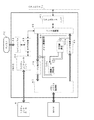
図2に、図1に示す複写機の電気系システムを示す。原稿を光学的に読み取る原稿スキャナ200は、読み取りユニット4にて、原稿に対するランプ照射の反射光をミラー及びレンズにより受光素子207に集光する。受光素子(本実施例ではCCD)は、センサー・ボード・ユニットSBU(以下単にSBUと称す)にあり、CCDに於いて電気信号に変換された画像信号は、SBU上でディジタル信号すなわち読取った画像デ−タに変換された後、SBUから、圧縮/伸張及びデータインターフェース制御部CDIC(以下単にCDICと称す)に出力される。
【0041】
すなわちSBUから出力される画像デ−タは、CDICに入力される。機能デバイス及びデータバス間における画像データの伝送は、CDICが全て制御する。すなわちCDICは、画像データに関し、SBU,パラレルバスPb,画像信号処理装置IPP(以下単にIPPと称す)間のデータ転送、ならびに、図2に示すデジタル複写機全体制御を司るシステムコントローラ6と、プロセスコントローラ1間の、画像データ転送およびその他の制御に関する通信を行う。システムコントローラ6とプロセスコントローラ1は、パラレルバスPb,CDIC及びシリアルバスSbを介して相互に通信を行う。CDICは、その内部に於いてパラレルバスPbとシリアルバスSbとのデータインターフェースのためのデータフォーマット変換を行う。
【0042】
SBUからの読取り画像デ−タは、CDICを経由してIPPに転送され、IPPが、光学系及びディジタル信号への量子化に伴う信号劣化(スキャナ系の信号劣化:スキャナ特性による読取り画像デ−タの歪)を補正し、再度CDICへ出力する。CDICは、該画像デ−タを複写機能コントロ−ラMFCに転送してメモリMEMに書込む。又は、IPPの、プリンタ出力のための処理系に戻す。
【0043】
すなわち、CDICには、読取り画像デ−タをメモリMEMに蓄積して再利用するジョブと、メモリMEMに蓄積しないでビデオ・データ制御VDC(以下、単にVDCと称す)に出力してレ−ザプリンタ400で作像出力するジョブとがある。メモリMEMに蓄積する例としては、1枚の原稿を複数枚複写する場合、読み取りユニット4を1回だけ動作させ、読取り画像デ−タをメモリMEMに蓄積し、蓄積データを複数回読み出す使い方がある。メモリMEMを使わない例としては、1枚の原稿を1枚だけ複写する場合、読取り画像デ−タをそのままプリンタ出力用に処理すれば良いので、メモリMEMへの書込みを行う必要はない。
【0044】
まず、メモリMEMを使わない場合、IPPからCDICへ転送された画像データは、再度CDICからIPPへ戻される。IPPに於いてCCDによる輝度データを面積階調に変換するための画質処理(図3の15)を行う。画質処理後の画像データはIPPからVDCに転送する。面積階調に変化された信号に対し、ドット配置に関する後処理及びドットを再現するためのパルス制御をVDCで行い、レ−ザプリンタ400の作像ユニット5に於いて転写紙上に再生画像を形成する。
【0045】
メモリMEMに蓄積し、それからの読み出し時に付加的な処理、例えば画像方向の回転,画像の合成等を行う場合は、IPPからCDICへ転送されたデータは、CDICからパラレルバスPbを経由して画像メモリアクセス制御IMAC(以下単にIMACと称す)に送られる。ここではシステムコントローラ6の制御に基づき画像データとメモリモジュ−ルMEM(以下単にMEMと称す)のアクセス制御,外部パソコンPC(以下単にPCと称す)のプリント用データの展開(文字コ−ド/キャラクタビット変換),メモリー有効活用のための画像データの圧縮/伸張を行う。IMACへ送られたデータは、データ圧縮後MEMへ蓄積し、蓄積データを必要に応じて読み出す。読み出しデータは伸張し、本来の画像データに戻しIMACからパラレルバスPb経由でCDICへ戻される。
【0046】
CDICからIPPへの転送後は、IPPでの画質処理及びVDCでのパルス制御を行い、作像ユニット5に於いて転写紙上に顕像(トナ−像)を形成する。
【0047】
画像データの流れに於いて、パラレルバスPb及びCDICでのバス制御により、デジタル複写機の複合機能を実現する。複写機能の1つであるFAX送信機能は、スキャナ200の読取り画像データをIPPにて画像処理を実施し、CDIC及びパラレルバスPbを経由してFAX制御ユニットFCU(以下単にFCUと称す)へ転送する。FCUにて公衆回線通信網PN(以下単にPNと称す)へのデータ変換を行い、PNへFAXデータとして送信する。FAX受信は、PNからの回線データをFCUにて画像データへ変換し、パラレルバスPb及びCDICを経由してIPPへ転送される。この場合特別な画質処理は行わず、VDCにおいてドット再配置及びパルス制御を行い、作像ユニット5に於いて転写紙上に顕像を形成する。
【0048】
複数ジョブ、例えばコピー機能,FAX送受信機能およびプリンタ出力機能、が並行に動作する状況に於いて、読み取りユニット4、作像ユニット5及びパラレルバスPb使用権のジョブへの割り振りを、システムコントロ−ラ6およびプロセスコントローラ1にて制御する。
【0049】
プロセスコントローラ1は、画像データの流れを制御し、システムコントローラはシステム全体を制御し、各リソースの起動を管理する。このデジタル複写機能複写機の機能選択は、操作ボ−ドOPBにて選択入力し、コピー機能,FAX機能等の処理内容を設定する。
【0050】
FAX送信機能は、読み取り画像データをIPPにて画像処理を実施し、CDIC及びパラレルバスを経由してFCU(FAX制御ユニット)へ転送する。FCUにて通信網へのデータ変換を行い、PN(公衆回線)へFAXデータとして送信する。FAX受信は、PNからの回線データをFCUにて画像データへ変換し、パラレルバス及びCDICを経由してIPPへ転送される。この場合特別な画質処理は行わず、VDCにおいてドット再配置及びパルス制御を行い、作像ユニットに於いて転写紙上に再生画像を形成する。
【0051】
図3に、IPPの画像処理機能の概要を示す。読取り画像デ−タは、SBUからCDICを介してIPPの入力I/F(インタ−フェイス)11からスキャナ画像処理12へ伝達される。読取りによる画像情報の劣化の補正を主目的にして、スキャナ画像処理12は、シェーディング補正,スキャナγ補正およびMTF補正等を行う。補正処理ではないが、拡大/縮小の変倍処理も行う。読取り画像データの補正処理終了後、出力I/F13を介してCDICへ画像データを転送する。転写紙への出力のときには、CDICからの画像データを入力I/F14より受け、まずフィルタ処理15aを実行し、そして画質処理15bに於いて面積階調処理を行う。画質処理後のデータは出力I/F16を介してVDCへ出力される。
【0052】
この実施例のフィルタ処理15aでは、IMACが後述のエッジ抽出処理によって生成したエッジ抽出データが画像データに付されているときには、エッジ抽出データがエッジを表すものであるとエッジ強調のフィルタ処理を画像データに施し、非エッジを表すものであると、中間調を滑らかに表す平滑化フィルタ処理を画像データに施す。画像データにエッジ抽出データの添付がないときには、エッジ強調と平滑化の略中間でややエッジ強調気味の中立特性のフィルタ処理を画像データに施す。
【0053】
面積階調処理は、濃度変換,ディザ処理,誤差拡散処理等が有り、階調情報の面積近似を主な処理とする。
【0054】
一旦スキャナ画像処理12を施した画像データをメモリMEMに蓄積しておけば、画質処理15で施す処理を変える事によって種々の再生画像を確認することができる。例えば再生画像の濃度を振ってみたり、ディザマトリクスの線数を変更してみたりする事で、再生画像の雰囲気を変更できる。この時処理を変更する度に画像をスキャナ200で読み込み直す必要はなく、MEMから格納画像を読み出せば同一データに対し、何度でも異なる処理を実施できる。
【0055】
図4に、CDICの機能構成の概要を示す。画像データ入出力制御21は、SBUからの読取り画像データを入力し、IPPに対してデータを出力する。画像データ入力制御22には、IPPで、スキャナ画像処理12でスキャナ画像補正された画像データが入力される。入力データは、パラレルバスPbでの転送効率を高めるためにデータ圧縮部23に於いて、データ圧縮を行う。圧縮した画像デ−タは、パラレルデータI/F25を介してパラレルバスPbへ送出される。パラレルデータバスPbからパラレルデータI/F25を介して入力される画像データは、バス転送のために圧縮されており、データ伸張部26で伸張される。伸張された画像データは、画像データ出力制御27によってIPPへ転送される。CDICは、パラレルデータとシリアルデータの変換機能を併せ持つ。システムコントローラ6は、パラレルバスPbにデータを転送し、プロセスコントローラ1は、シリアルバスSbにデータを転送する。2つのコントローラ6,1の通信のために、デ−タ変換部24およびシリアルデ−タI/F29で、パラレル/シリアルデータ変換を行う。シリアルデータI/F28は、IPP用であり、IPPともシリアルデ−タ転送する。
【0056】
図5に、VDCの機能構成の概要を示す。VDCは、IPPから入力される画像データに対し作像ユニット5の特性に応じて、追加の処理を行う。エッジ平滑処理によるドットの再配置処理,ドット形成のための画像信号のパルス制御を行い、画像データは作像ユニット5を対象として出力される。画像データの変換とは別に、パラレルデータとシリアルデータのフォーマット変換機能33〜35を併せ持ち、VDC単体でもシステムコントローラ6とプロセスコントローラ1の通信に対応できる。
【0057】
図6に、IMACの機能構成の概略を示す。パラレルデータI/F41に於いて、パラレルバスPbに対する画像データの入,出力を管理し、MEMへの画像データの格納/読み出しと、主に外部のPCから入力されるコードデータの画像データへの展開を制御する。PCから入力されたコードデータは、ラインバッファ42に格納する。すなわち、ローカル領域でのデータの格納を行い、ラインバッファ42に格納したコードデータは、システムコントローラI/F44を介して入力されたシステムコントローラ6からの展開処理命令に基づき、ビデオ制御43に於いて画像データに展開する。展開された画像データもしくはパラレルデータI/F41を介してパラレルバスPbから入力された画像データは、MEMに格納される。この場合、データ変換部45に於いて格納対象となる画像データを選択し、データ圧縮部46においてメモリ使用効率を上げるためにデータ圧縮を行い、メモリアクセス制御部47にてMEMのアドレスを管理しながらMEMに画像データを格納する。MEMに格納された画像データの読み出しは、メモリアクセス制御部47にて読み出し先アドレスを制御し、読み出された画像データをデータ伸張部48にて伸張する。伸張された画像データをパラレルバスPbへ転送する場合、パラレルデータI/F41を介してデータ転送を行う。
【0058】
スキャナ200からの画像データをIPPでスキャナ画像処理12を施してMEMに蓄積したときには、IMACは、蓄積した画像データを読み出して、メモリ画像処理49を実施して、この処理を終えた画像データに、蓄積した画像データを更新する。この第1実施例では、メモリ画像処理49の内容は、画像データのエッジ抽出である。
【0059】
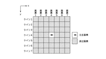
すなわち、MEMから読み出した画像データに対し、IMAC内のマトリクス生成49aで、図8に示すような画像データマトリクス生成を行う。マトリクス生成後、積和演算49bで、図9および図10に示したエッジ抽出フィルタ係数マトリクスEDP1〜EDP8のそれぞれと、マトリクス上画像データとの積和演算を行って、積和演算値が設定値より大きいと、その時の注目画素(の画像データ)がエッジであると判定し、設定値未満であると非エッジと判定する。
【0060】
エッジ抽出フィルタEDP1〜EDP8には、横エッジ抽出フィルタ、縦エッジ抽出フィルタ、左上がり斜めエッジ抽出フィルタ、右上がり斜めエッジ抽出フィルタがあり、それら全てEDP1〜EDP8について、それに該当するエッジであるかの処理および判定を行う。
【0061】
すなわち、各エッジ抽出フィルタとの積和演算結果をエッジ判定49cで予め設定されたしきい値と比較し、積和演算値がしきい値以上の場合、エッジと判定する。このエッジ判定結果は、コード生成49dで、100:横エッジ、101:縦エッジ、110:左上がり斜めエッジ、111:右上がり斜めエッジ、000:非エッジ、のようにコード化し、画像データ再生成49eでMEMから入力された画像データに付加して、再びMEMに蓄積する。すなわちMEM上の画像データを、該画像データにエッジ判定コードを付加した複合画像データに更新する。
【0062】
以上の処理をMEMに蓄積された画像データ全てについて行い、全ての画像データについての処理が完了後、MEM内の画像データは、CDICを介してIPPに送られる。IPP(図3)のフィルタ処理15aでは、画像データに付加されて入力されるかがあらわす内容(判定結果)を特徴量として、IPP内で行われるフィルタリングのフィルタ係数を適応的に切り替える。すなわち、100:横エッジのときには、画像データ白エッジ(低濃度)か黒エッジ(高濃度)かに応じて、横白エッジ強調フィルタか横黒エッジ強調フィルタを選択して、フィルタリングする。101:縦エッジ、110:左上がり斜めエッジあるいは111:右上がり斜めエッジの場合も、同様な方向性があるエッジ強調処理を行う。000:非エッジのときには、濃淡変化を滑らかにする平滑化フィルタリングを行う。
【0063】
なお、ここでは、図8,図9及び図10に示すように、7×7サイズのマトリクスによるエッジ抽出を例に挙げたが、その限りではなく、IMAC内のマトリクス生成49a、積和演算49bの構成を変更することによって、任意のサイズのエッジ抽出フィルタによる処理が可能である。
【0064】
図7に、MEMに画像を蓄積する処理ならびにMEMから画像を読出す処理のフローを示す。(a)は画像スキャナ200が発生する画像データをMEMに書き込み、そして上述のメモリ画像処理49でエッジ判定をして判定結果をしめすコードをMEMに蓄積するまでの画像データの処理あるいは転送過程Ip1〜Ip14を示し、(b)はMEMから画像データを読み出して、プリンタ400に出力するまでの画像データの処理あるいは転送過程Op1〜Op13を示す。CDICの制御により、このようなバス及びユニット間のデータフローが制御される。読み取り画像データに関してはIPPでのスキャナ画像処理Ip1〜Ip13(図3の12)およびIMACでのメモリ画像処理(エッジ判定)Ip14(49)を、プリンタ400へ出力のための画像データに関してはIPPでのフィルタ処理および画質処理Op1〜Op13(図3の15a,15b)を独立に実施する。
【0065】
−第2実施例−
図11に、本発明の第2実施例で用いるIMACの機能構成の概要を示す。この第2実施例では、MEMに蓄積された画像データに対してIMACで行われる画像処理は、平均値演算である。注目画素とその周辺画素をMEMから任意の画素数分取り出し、IMAC内の平均値算出50aで取り出した任意の画素数分の平均値を算出する。平均値算出50aで算出された注目画素とその周辺画素の平均値は、画像データ再生成50bで画像データに付加され、再びMEMに蓄積される。以上の処理をMEMに蓄積された画像データ全てについて行い、全ての画像データについての処理が完了後、MEM内の画像データは、CDICを介してIPPに送られる。
【0066】
図12に、本発明の第2実施例で用いるIPPの機能構成の概要を示す。IPPでは、フィルタ処理15cにおいて、画像データに付加されて入力される周辺画素との平均値を特徴量として、IPP内で行われるフィルタリングのフィルタ係数を画像の高濃度部と低濃度部で適応的に切り替える。すなわち、平均値が高いと濃淡を強調するフィルタリングを、平均値が低いと濃淡を抑制するフイルタリングを行う。
【0067】
以上の例では、画素ごとに注目画素とその周辺画素との平均値を算出する例を示したが、画像データ1ラインごとに1ライン分の平均値を算出し、1ラインに1つの平均値データを付加することも可能である。IMACは、MEMに対してランダムにアクセス可能であるので、任意の位置の画像データに対する平均値を算出することが可能である。
【0068】
−第3実施例−
図13に、本発明の第3実施例で用いるIMACの機構構成の概要を示す。この第3実施例では、MEMに蓄積された画像データに対してIMACで行われる画像処理は、パターンマッチング処理である。ここでは、画像の孤立点検知のパターンマッチングを行う。MEMから取り出された画像データに対し、IMAC内のマトリクス生成51aでマトリクス生成を行う。マトリクス生成後、パターンマッチング51bで、図14に示した各種マッチングパターンとの比較を行う。
【0069】
図14のマッチングパターンからわかるように、孤立点検知では、黒画素に囲まれた白画素、または、白画素に囲まれた黒画素を孤立点として検出する。パターンとの比較結果から、マッチング判定51cでいずれかのマッチングパターンにヒットしたか否かの判定を行う。この判定結果を、コード生成51dが、0:非孤立点、1:孤立点、のようなコード化し、画像データ再生成51eが、MEMから入力された画像データにコードを付加して、再びMEMに蓄積する。以上の処理をMEMに蓄積された画像データ全てについて行い、全ての画像データについての処理が完了後、MEM内の画像データは、CDICを介してIPPに送られる。
【0070】
図15に、本発明の第2実施例で用いるIPPの機能構成の概要を示す。IPPでは、画像データに付加されて入力されるパターンマッチング判定結果をもとに、IPP内で孤立点除去処理15dを行う。すなわち、注目画素を中心またはほぼ中心とする画像データ群が、図14のパターンのいずれかに該当し、注目画像データがパターン上の×印画素に該当すると、周辺画素(〇印)の平均値に注目画素の画像データを変更する。
【0071】
ここでは、孤立点検知のパターンマッチングを例に挙げ説明したが、マッチングパターンは、その限りではなく、任意のサイズの、任意のマッチングパターンにも応用可能である。
【0072】
−第4実施例−
図16に、本発明の第4実施例で用いるIMACの機能構成の概要を示す。この第4実施例では、MEMに蓄積された画像データに対してIMACで行われる画像処理は、画像データの周波数分析処理であるす。ここでは、この周波数分析のための周波数変換に、離散ウェーブレットの方法を用いる。MEMから取り出された画像データに対し、IMAC内の周波数変換52aで離散ウェーブレット変換により周波数変換を行う。画像データの周波数変換後、主要周波数成分判定52bで、画像データがどの周波数帯域の成分を多くもつ信号なのか判定する。離散ウェーブレット変換を1回行うと、画像データが、LL(低低)、HL(低)、LH(高)、HH(高高)の4つの周波数成分に分解される。これら4つの周波数成分から主要周波数成分判定52bで最もエネルギーが集中している周波数成分を選び出し、その周波数成分を画像データの主要周波数成分とする。主要周波数成分判定後、コード生成52cで判定された主要周波数成分がLL(低低)、HL(低)、LH(高)、HH(高高)のいずれであるかを示すコードを生成する。具体的には、00:LL、01:HL、10:LH、11:HH のようにコード化する。生成されたコードは、画像データ再生成52dでMEMから入力された画像データに付加され、再びMEMに蓄積される。
【0073】
以上の処理をMEMに蓄積された画像データに対して、離散ウェーブレット変換を行うブロックごとに繰り返す。全ての画像データについての処理が完了後、MEM内の画像データは、CDICを介してIPPに送られる。
【0074】
図17に、本発明の第4実施例で用いるIPPの機能構成の概要を示す。IPPでは、画像データに付加されて入力される離散ウェーブレット変換による周波数分析結果を特徴量として、IPP内でフィルタリング処理のフィルタ係数の切り替えを行う。すなわち、コードが表すLL(低低)、HL(低)、LH(高)又は、HH(高高)、の周波数の画像を最も明瞭に表現するフィルタ処理を施す。
【0075】
以上では、周波数変換の方法が離散ウェーブレット変換の場合について説明したが、周波数変換方法として離散フーリエ変換など他の周波数変換方法を用いてもよい。
【図面の簡単な説明】
【図1】 本発明の一実施例のデジタルカラー複写機の機構概要を示す縦断面図である。
【図2】 図1に示す複写機の電気制御システムの構成の概要を示すブロック図である。
【図3】 図2に示す画像信号処理装置IPPの機能構成を示すブロック図である。
【図4】 図2に示す圧縮/伸張及びデ−タインタ−フェ−ス制御部CDICの機能構成を示すブロック図である。
【図5】 図2に示すビデオ・デ−タ制御VDCの機能構成を示すブロック図である。
【図6】 図2に示す画像メモリアクセス制御IMACの機能構成を示すブロック図である。
【図7】 (a)は、図2に示すスキャナ200で読み取った画像データを画像メモリMEMに書込み、さらにIMACでしょりしてMEMに更新書き込みするまでの画像データの流れと処理を示すフローチャート、(b)は、画像メモリMEMから画像データを読み出してプリンタ400に出力するまでの画像データの流れと処理を示すフローチャートである。
【図8】 図6に示すマトリクス生成49aで摘出する画像データ群の、対応画素の分布を示す平面図である。
【図9】 図6に示す積和算出49bで画像データ群に宛てる乗算係数の分布4種を示す平面図である。
【図10】 図6に示す積和算出49bで画像データ群に宛てる乗算係数の分布の、他4種を示す平面図である。
【図11】 本発明の第2実施例において用いるIMACの機能構成を示すブロック図である。
【図12】 本発明の第2実施例において用いるIPPの機能構成を示すブロック図である。
【図13】 本発明の第3実施例において用いるIMACの機能構成を示すブロック図である。
【図14】 図13に示すパターンマッチング51bでそうであるかとチェックする、孤立点分布パターンを示す平面図である。
【図15】 本発明の第3実施例において用いるIPPの機能構成を示すブロック図である。
【図16】 本発明の第4実施例において用いるIMACの機能構成を示すブロック図である。
【図17】 本発明の第4実施例において用いるIPPの機能構成を示すブロック図である。
【符号の説明】
200:原稿読取りスキャナ 400:フルカラープリンタ
IPP:画像信号処理装置
CDIC:圧縮/伸張及びデ−タインタ−フェ−ス制御部
VDC:ビデオ・デ−タ制御 IMAC:画像メモリアクセス制御
FCU:FAX送受信部 SBU:センサ−・ボ−ド・ユニット
PN:公衆回線[0001]
BACKGROUND OF THE INVENTION
The present invention relates to an image processing apparatus that processes digitally generated image information, that is, image data, so as to represent a high-quality image, and an electronic image reader in combination with the image processing apparatus to generate high-quality image data. And an image forming apparatus for forming an image represented by image data processed by the image processing apparatus on a sheet by combining the image processing apparatus or the image reading apparatus with an image recording apparatus. , Regarding. These are implemented in, for example, a document scanner, a facsimile, an image printer, or a digital copying machine.
[0002]
More specifically, the present invention relates to SIMD (Single Instruction Stream Multi-Data Stream) type image processing operation by temporarily storing image data in a memory device and performing image processing on the stored image data. Image processing that cannot or cannot be realized by arithmetic processing means using a processor, such as edge extraction with reference to a wide image range, pattern matching, frequency analysis, and average value calculation of a wide image range, etc. The present invention relates to the efficiency of image processing performed by a memory access control unit capable of referring to a range and assisting image processing in a SIMD type image processing arithmetic processor.
[0003]
[Prior art]
Conventionally, a programmable image processing LSI (Japanese Patent Laid-Open No. 8-50651) that can perform feature extraction and pattern matching processing has been invented as preprocessing of image processing. Both preprocessing (feature extraction) for image processing and image processing based on feature amounts can be performed.
[0004]
[Problems to be solved by the invention]
However, in order to increase the reliability of feature extraction and / or to further improve the quality of image processing, it is desirable to perform feature extraction and pattern matching with reference to image data over a wide range. When trying to do so, it is necessary to secure a large memory capacity for image processing on the image processing arithmetic processor.
[0005]
In MFPs (multifunction machines with various functions such as copying, faxing, printers, and scanners), they are relatively large for the purpose of copying multiple copies in addition to the image processing LSI memory. A memory device having a capacity is provided, and image data for one document or more is stored. While image data is stored in the memory device, image reference over a wide range is possible.
[0006]
The first object of the present invention is to improve the quality of image data, and the second object is to facilitate the quality improvement processing by the arithmetic processing means. More specifically, a programmable arithmetic processing unit having a SIMD type image processing arithmetic processor as a main element realizes image processing with reference to a wide range of image areas that is impossible or difficult to realize. The fourth object is to efficiently perform the image processing by the SIMD type image processing arithmetic processor. A fifth object of the present invention is to provide an image reading apparatus that stores image data that can be easily subjected to high-quality processing in a memory device, and an image forming apparatus that performs high-quality processing and prints out the image data stored in the memory device It is a sixth object to provide
[0007]
[Means for Solving the Problems]
(1) Image dataTProgrammable processing means (IPP) to process;
Data bus (Pb) ;
Memory device (MEM);
The image data given by the image data input means (200, FCU, PC)Said arithmetic processing means (IPP) Given to , The arithmetic processing means (IPP) The image data processed by the data bus (Pb) The memory device (MEM) To the data bus (Pb) The operation processing means (IPP) Give to,TheFor arithmetic processing means (IPP)SaidData bus(Pb)Image bus management means (CDIC) that collectively manages image data transmission and reception;
The data bus (Pb) The arithmetic processing means sent to (IPP) ProcessedImage data is stored in the memory device (MEM), and the stored image dataPerform image feature extraction processing The memory device by adding extracted data to image data (MEM) And the stored image data with the extracted data added is stored in the data bus. (Pb) Send to the aboveA memory management means (IMAC) that collectively manages image data transmission / reception of the data bus with respect to the memory device (MEM);
Said arithmetic processing means (IPP) The memory management means (IMAC) By the memory device (MEM) To the data bus (Pb) The image bus management means sent to (CDIC) By the data bus (Pb) To the arithmetic processing means (IPP) The image data to which the extracted data given to the image data is added is adapted to the image characteristics based on the extracted data.Apply image processingPictureImage processing device.
[0008]
In order to facilitate understanding, reference numerals or corresponding matters of corresponding elements in the embodiments shown in the drawings and described later are added in parentheses for reference. The same applies to the following.
[0009]
According to this image processing apparatus, the image data stored in the memory device (MEM) connected to the memory management means (IMAC) is sequentially extracted by the memory management means (IMAC), and feature amount extraction is performed.OutgoingImage processing is performed, the image processing result is added to the image data, stored again in the memory device (MEM), and when all the image processing by the memory management means (IMAC) is completed, that is, the memory management means (IMAC ) When all the image data added with the image processing results performed in () is arranged on the memory device (MEM), the image data is sent to the arithmetic processing means (IPP) via the image bus management means (CDIC). In the sending and calculation processing means (IPP), the image processing result in the memory management means (IMAC) added to the image data is used as the image feature amount, or the image processing method is switched. it can.
[0010]
Programmable processing means (IPP)Is realReferencing a wide range of image areas that are currently impossible or difficult to achieveImage feature extraction processingWhile the image data is stored in the memory device (MEM), access to the memory device (MEM) is managed collectively.Memory managementIt is performed in the means (IMAC), and the image processing in the arithmetic processing means (IPP), for example, the SIMD type image processing arithmetic processor is assisted to realize efficient image processing.
[0011]
DETAILED DESCRIPTION OF THE INVENTION
(2) The memory management means (IMAC)Image feature extraction processingIs an edge extraction process of the image, and when the memory management means (IMAC) sends the image data to the arithmetic processing means (IPP), the edge extraction result is added to the image data and sent; IPP) processes image data using the edge extraction result as a feature amount.
[0012]
According to this, in the memory management means (IMAC) that collectively manages access to the memory device (MEM), by performing edge extraction processing on the image data stored in the memory device (MEM), a wide range of Edge extraction processing with reference to an image is enabled, and the calculation result is sent together with image data to an arithmetic processing means (IPP), for example, a SIMD type image processing arithmetic processor, thereby performing image processing in the SIMD type image processing arithmetic processor. It can be more effective and efficient.
[0013]
(3) The memory management means (IMAC)Image feature extraction processingIs the average value calculation of the image data of the target pixel and the surrounding pixels, and the memory management means (IMAC) adds the average value calculation result to the image data when sending the image data to the calculation processing means (IPP). The calculation processing means (IPP) processes the image data using the average value calculation result as a feature amount.
[0014]
According to this, in the means (IMAC) for collectively managing access to the memory device (MEM), the average value calculation of the peripheral pixels including the target pixel is performed on the image data stored in the memory device (MEM). Thus, it is possible to calculate an average value for a wide range of image data, and send the calculation result together with the image data to an arithmetic processing means (IPP) such as a SIMD type image processing arithmetic processor. The processing can be made more effective and efficient.
[0015]
(4) The memory management means (IMAC)Image feature extraction processingIs a pattern matching process, and when the memory management means (IMAC) sends the image data to the arithmetic processing means (IPP), the pattern matching result is added to the image data and sent; the arithmetic processing means (IPP) The image data is processed using the pattern matching result as a feature amount.
[0016]
According to this, a wide range of image data can be obtained by performing pattern matching processing on the image data stored in the memory device (MEM) in the means (IMAC) that collectively manages access to the memory device (MEM). The image processing in the SIMD type image processing arithmetic processor is more effective by sending the result of the calculation together with the image data to the arithmetic processing means (IPP) such as the SIMD type image processing arithmetic processor. And efficient.
[0017]
(5) The memory management means (IMAC)Image feature extraction processingIs a frequency analysis process of image data, and when the memory management means (IMAC) sends the image data to the arithmetic processing means (IPP), it adds the frequency analysis result to the image data and sends it; the arithmetic processing means (IPP) processes image data using a frequency analysis result as a feature quantity.
[0018]
According to this, a wide range of image data can be obtained by performing frequency analysis processing on the image data stored in the memory device (MEM) in the means (IMAC) for collectively managing access to the memory device (MEM). The frequency analysis process can be performed with reference to the image processing result, and the calculation result is sent together with the image data to the calculation processing means (IPP), for example, the SIMD type image processing calculation processor. It can be effective and efficient.
[0019]
(6) The image processing apparatus according to (1), (2), (3), (4) or (5); and an image represented by the image data processed by the arithmetic processing means (IPP) on a sheet An image forming apparatus comprising: an image recording apparatus (400) to be formed.
[0020]
According to this, it is possible to print out image data with high image quality on paper.
[0021]
(7) The image processing apparatus according to the above (1), (2), (3), (4) or (5); and the image is read and converted into digitized image data, and the image processing apparatus The image bus management means (CDIC) collectively manages the image reading means (200) and image data transmission / reception of the data bus to the arithmetic processing means (IPP). Reader.
[0022]
According to this, the image data obtained by the image reading means (200) is read and corrected by the arithmetic processing means (IPP), then stored in the memory device (MEM), and the image data stored in the memory device (MEM). Can be sequentially extracted by the memory management means (IMAC), image processing such as feature extraction and pattern matching can be performed, and the image processing result can be added to the image data and stored again in the memory device (MEM).
[0023]
(8) An image forming apparatus comprising: the image reading apparatus according to (7); and an image recording apparatus (400) that forms an image represented by the image data processed by the arithmetic processing unit (IPP) on a sheet. According to this, the image data obtained by the image reading device can be printed out on the high quality paper.
[0024]
(9) The arithmetic processing means (IPP) of (2) above uses the edge extraction result as a feature quantity, performs edge enhancement filter processing on edge region image data, and smoothing filter on non-edge region image data. Processing is performed (15a in FIG. 3). Thereby, the character image is clearly displayed, and the density change of the halftone image is smoothly expressed.
[0025]
(10) The arithmetic processing means (IPP) of (3) above uses a mean value calculation result as a feature value, and performs filter processing for emphasizing shading in high density image data, and shading in low density image data. A filter process for smoothing the change is performed (15c in FIG. 12). Thereby, the contrast of the high density part is high, and the density change is smoothly expressed in the low density part.
[0026]
(11) The arithmetic processing means (IPP) of (4) above uses the pattern matching result as a feature amount and replaces the image data of the isolated point in the region matching the isolated point pattern with the surrounding image data (FIG. 15). 15d). As a result, isolated points (noise) on the image disappear.
[0027]
(12) The arithmetic processing means (IPP) of (5) performs a filter process for improving the image quality of the image component of the main frequency component on the image data using the frequency analysis result as a feature amount (15e in FIG. 17). The main components of the image are clearly represented.
[0028]
Other objects and features of the present invention will become apparent from the following description of embodiments with reference to the drawings.
[0029]
【Example】
-1st Example-
An outline of the mechanism of one embodiment of the present invention is shown in FIG. This embodiment is a digital full-color copying machine. A color image reading apparatus (hereinafter referred to as a scanner) 200 forms an image of a
[0030]
Using this color image data, Bk, C, M, and Y images are formed on an intermediate transfer belt by a color image recording apparatus (hereinafter referred to as a color printer) 400 described below, and transferred onto transfer paper. The
[0031]
A writing
[0032]
The
[0033]
When the image forming cycle is started, the
[0034]
The
[0035]
The
[0036]
A paper transfer corona discharger (hereinafter referred to as a paper transfer unit) 417 is a corona discharge method for transferring the superimposed toner image on the
[0037]
The
[0038]
The surface of the
[0039]
The color copier shown in FIG. 1 can print out (image output) with a
[0040]
FIG. 2 shows an electric system of the copying machine shown in FIG. In the
[0041]
That is, the image data output from the SBU is input to the CDIC. The CDIC controls all image data transmission between the functional device and the data bus. That is, the CDIC relates to image data, a data transfer between the SBU, the parallel bus Pb, and the image signal processing device IPP (hereinafter simply referred to as IPP), and a
[0042]
The read image data from the SBU is transferred to the IPP via the CDIC, and the IPP performs signal deterioration due to quantization into an optical system and a digital signal (signal deterioration of the scanner system: read image data due to scanner characteristics). The distortion is corrected and output to the CDIC again. The CDIC transfers the image data to the copy function controller MFC and writes it in the memory MEM. Or, return to the IPP processing system for printer output.
[0043]
That is, the CDIC stores the read image data in the memory MEM for reuse, and outputs it to the video data control VDC (hereinafter simply referred to as VDC) without storing it in the memory MEM. There is a job for creating and outputting an image with the
[0044]
First, when the memory MEM is not used, the image data transferred from the IPP to the CDIC is returned from the CDIC to the IPP again. In the IPP, image quality processing (15 in FIG. 3) for converting luminance data from the CCD into area gradation is performed. The image data after the image quality processing is transferred from the IPP to the VDC. With respect to the signal changed to the area gradation, post-processing relating to dot arrangement and pulse control for reproducing the dots are performed by the VDC, and a reproduced image is formed on the transfer paper in the
[0045]
When additional processing such as rotation in the image direction, image synthesis, etc. is performed when reading from the memory MEM, data transferred from the IPP to the CDIC is transferred from the CDIC to the image via the parallel bus Pb. It is sent to the memory access control IMAC (hereinafter simply referred to as IMAC). Here, based on the control of the
[0046]
After transfer from the CDIC to the IPP, image quality processing by the IPP and pulse control by the VDC are performed, and a visible image (toner image) is formed on the transfer paper in the
[0047]
In the flow of image data, the composite function of the digital copying machine is realized by the bus control by the parallel bus Pb and the CDIC. The FAX transmission function, which is one of the copying functions, performs image processing on the scanned image data of the
[0048]
In a situation where a plurality of jobs, for example, a copy function, a FAX transmission / reception function and a printer output function operate in parallel, the system controller allocates the
[0049]
The
[0050]
The FAX transmission function performs image processing on the read image data by IPP, and transfers it to the FCU (FAX control unit) via the CDIC and the parallel bus. Data conversion to the communication network is performed by the FCU, and the data is transmitted to the PN (public line) as FAX data. In FAX reception, line data from the PN is converted into image data by the FCU, and transferred to the IPP via the parallel bus and CDIC. In this case, special image quality processing is not performed, dot rearrangement and pulse control are performed in the VDC, and a reproduced image is formed on the transfer paper in the image forming unit.
[0051]
FIG. 3 shows an outline of the image processing function of IPP. The read image data is transmitted from the IPP input I / F (interface) 11 to the
[0052]
In the filter processing 15a of this embodiment, when the edge extraction data generated by the IMAC by the edge extraction processing described later is attached to the image data, the edge enhancement filtering processing is performed if the edge extraction data represents an edge. If it is applied to the data and represents a non-edge, a smoothing filter process that smoothly represents a halftone is applied to the image data. When no edge extraction data is attached to the image data, a neutral characteristic filtering process is applied to the image data slightly between edge enhancement and smoothing.
[0053]
The area gradation processing includes density conversion, dither processing, error diffusion processing, and the like, and mainly performs area approximation of gradation information.
[0054]
Once the image data subjected to the
[0055]
FIG. 4 shows an outline of the functional configuration of the CDIC. The image data input / output control 21 inputs the read image data from the SBU and outputs the data to the IPP. The image
[0056]
FIG. 5 shows an outline of the functional configuration of the VDC. The VDC performs additional processing on the image data input from the IPP according to the characteristics of the
[0057]
FIG. 6 shows an outline of the functional configuration of the IMAC. In the parallel data I /
[0058]
When the image data from the
[0059]
That is, image data matrix generation as shown in FIG. 8 is performed on the image data read from the MEM by the matrix generation 49a in the IMAC. After the matrix is generated, a product-sum operation 49b performs a product-sum operation on each of the edge extraction filter coefficient matrices EDP1 to EDP8 shown in FIGS. If it is larger, it is determined that the target pixel (image data) at that time is an edge, and if it is less than the set value, it is determined that it is a non-edge.
[0060]
The edge extraction filters EDP1 to EDP8 include a horizontal edge extraction filter, a vertical edge extraction filter, a left rising oblique edge extraction filter, and a right rising oblique edge extraction filter, all of which are the corresponding edges for EDP1 to EDP8. Process and determine.
[0061]
That is, the product-sum operation result with each edge extraction filter is compared with a threshold value set in advance in the edge determination 49c. The edge determination result is code generation 49d, which is encoded as 100: horizontal edge, 101: vertical edge, 110: left-up diagonal edge, 111: right-up diagonal edge, 000: non-edge, and image data is regenerated. At 49e, the image data is added to the image data input from the MEM and stored in the MEM again. That is, the image data on the MEM is updated to composite image data obtained by adding an edge determination code to the image data.
[0062]
The above processing is performed for all the image data stored in the MEM, and after the processing for all the image data is completed, the image data in the MEM is sent to the IPP via the CDIC. In the IPP (FIG. 3) filter processing 15a, the filter coefficient of filtering performed in the IPP is adaptively switched with the content (determination result) indicating whether it is added to the image data and input. That is, at 100: horizontal edge, the horizontal white edge enhancement filter or the horizontal black edge enhancement filter is selected and filtered according to whether the image data white edge (low density) or black edge (high density). 101: Vertical edge, 110: Left-up diagonal edge, or 111: Right-up diagonal edge, edge enhancement processing with the same direction is performed. 000: When non-edge, smoothing filtering is performed to smooth the change in shading.
[0063]
Here, as shown in FIGS. 8, 9, and 10, edge extraction using a 7 × 7 size matrix is given as an example. However, the present invention is not limited to this, and matrix generation 49a and product-sum operation 49b in IMAC are not limited thereto. By changing the configuration, it is possible to perform processing using an edge extraction filter of an arbitrary size.
[0064]
FIG. 7 shows a flow of processing for accumulating an image in the MEM and processing for reading an image from the MEM. (A) Writes image data generated by the
[0065]
-Second Example-
FIG. 11 shows an outline of the functional configuration of the IMAC used in the second embodiment of the present invention. In the second embodiment, the image processing performed by the IMAC on the image data stored in the MEM is an average value calculation. The pixel of interest and its surrounding pixels are extracted from the MEM for an arbitrary number of pixels, and the average value for the arbitrary number of pixels extracted by the average value calculation 50a in the IMAC is calculated. The average value of the target pixel and its surrounding pixels calculated by the average value calculation 50a is added to the image data by the image data regeneration 50b, and is stored again in the MEM. The above processing is performed for all the image data stored in the MEM, and after the processing for all the image data is completed, the image data in the MEM is sent to the IPP via the CDIC.
[0066]
FIG. 12 shows an outline of the functional configuration of the IPP used in the second embodiment of the present invention. In the IPP, in the
[0067]
In the above example, an example is shown in which the average value of the target pixel and its peripheral pixels is calculated for each pixel. However, an average value for one line is calculated for each line of image data, and one average value for each line. It is also possible to add data. Since the IMAC can randomly access the MEM, it is possible to calculate an average value for image data at an arbitrary position.
[0068]
-Third Example-
FIG. 13 shows an outline of the mechanism configuration of the IMAC used in the third embodiment of the present invention. In the third embodiment, the image processing performed by the IMAC on the image data stored in the MEM is a pattern matching process. Here, pattern matching for detecting isolated points of the image is performed. Matrix generation is performed on the image data extracted from the MEM by the matrix generation 51a in the IMAC. After the matrix is generated, the pattern matching 51b is compared with various matching patterns shown in FIG.
[0069]
As can be seen from the matching pattern in FIG. 14, in isolated point detection, a white pixel surrounded by black pixels or a black pixel surrounded by white pixels is detected as an isolated point. From the comparison result with the pattern, it is determined whether or not any matching pattern is hit in the matching
[0070]
FIG. 15 shows an outline of the functional configuration of the IPP used in the second embodiment of the present invention. In the IPP, the isolated
[0071]
Here, the pattern matching for isolated point detection has been described as an example, but the matching pattern is not limited thereto, and can be applied to an arbitrary matching pattern of an arbitrary size.
[0072]
-Fourth embodiment-
FIG. 16 shows an outline of the functional configuration of the IMAC used in the fourth embodiment of the present invention. In the fourth embodiment, the image processing performed by the IMAC on the image data stored in the MEM is image data frequency analysis processing. here,ThisThe discrete wavelet is used for frequency conversion for frequency analysis ofLawIs used. The image data taken out from the MEM is subjected to frequency conversion by discrete wavelet conversion by the frequency conversion 52a in the IMAC. After the frequency conversion of the image data, the main frequency component determination 52b determines which frequency band the image data has many components. When the discrete wavelet transform is performed once, the image data is decomposed into four frequency components of LL (low / low), HL (low), LH (high), and HH (high / high). From these four frequency components, the frequency component with the most concentrated energy is selected in the main frequency component determination 52b, and the frequency component is set as the main frequency component of the image data. After determining the main frequency component, a code indicating whether the main frequency component determined by the
[0073]
The above processing is repeated for each block on which discrete wavelet transform is performed on the image data stored in the MEM. After the processing for all the image data is completed, the image data in the MEM is sent to the IPP via the CDIC.
[0074]
FIG. 17 shows an outline of the functional configuration of the IPP used in the fourth embodiment of the present invention. In the IPP, the filter coefficient of the filtering process is switched in the IPP using the frequency analysis result by the discrete wavelet transform input by being added to the image data as a feature amount. In other words, a filter process that most clearly represents an image having a frequency of LL (low / low), HL (low), LH (high), or HH (high / high) represented by the code is performed.
[0075]
Although the case where the frequency conversion method is the discrete wavelet transform has been described above, other frequency conversion methods such as a discrete Fourier transform may be used as the frequency conversion method.
[Brief description of the drawings]
FIG. 1 is a longitudinal sectional view showing an outline of the mechanism of a digital color copying machine according to an embodiment of the present invention.
FIG. 2 is a block diagram showing an outline of a configuration of an electric control system of the copying machine shown in FIG.
3 is a block diagram showing a functional configuration of the image signal processing device IPP shown in FIG. 2;
4 is a block diagram showing a functional configuration of a compression / decompression and data interface control unit CDIC shown in FIG. 2; FIG.
FIG. 5 is a block diagram showing a functional configuration of the video data control VDC shown in FIG. 2;
6 is a block diagram showing a functional configuration of an image memory access control IMAC shown in FIG. 2. FIG.
7A is a flowchart showing the flow and processing of image data until image data read by the
8 is a plan view showing the distribution of corresponding pixels in the image data group extracted by the matrix generation 49a shown in FIG. 6. FIG.
9 is a plan view showing four types of distribution of multiplication coefficients addressed to the image data group in the product-sum calculation 49b shown in FIG.
10 is a plan view showing other four types of distribution of multiplication coefficients addressed to the image data group in the product-sum calculation 49b shown in FIG.
FIG. 11 is a block diagram showing a functional configuration of IMAC used in the second embodiment of the present invention.
FIG. 12 is a block diagram showing a functional configuration of IPP used in the second embodiment of the present invention.
FIG. 13 is a block diagram showing a functional configuration of IMAC used in the third embodiment of the present invention.
14 is a plan view showing an isolated point distribution pattern that is checked whether it is the case with the pattern matching 51b shown in FIG. 13; FIG.
FIG. 15 is a block diagram showing a functional configuration of IPP used in the third embodiment of the present invention.
FIG. 16 is a block diagram showing a functional configuration of an IMAC used in the fourth embodiment of the present invention.
FIG. 17 is a block diagram showing a functional configuration of an IPP used in a fourth embodiment of the present invention.
[Explanation of symbols]
200: Document reading scanner 400: Full color printer
IPP: Image signal processing device
CDIC: compression / decompression and data interface controller
VDC: Video data control IMAC: Image memory access control
FCU: FAX transmission / reception unit SBU: Sensor board unit
PN: Public line
Claims (6)
データバス;
メモリ装置;
画像データ入力手段が与える画像データを前記演算処理手段に与え、該演算処理手段が処理した画像データを前記データバスに送出し、前記メモリ装置から前記データバスに読み出されたデータを該演算処理手段に与える、該演算処理手段に対する前記データバスの画像データ送受、を一括管理する画像バス管理手段;および、
前記データバスに送出される、前記演算処理手段が処理した画像データを前記メモリ装置に蓄積して、蓄積した画像データに対して画像特徴の抽出処理をして抽出データを画像データに付加して前記メモリ装置に蓄積し、該蓄積した、抽出データを付加した画像データを前記データバスに送出する、前記メモリ装置に対する、前記データバスの画像データ送受を一括管理するメモリ管理手段;を備え、
前記演算処理手段が、前記メモリ管理手段により前記メモリ装置から前記データバスに送出され前記画像バス管理手段により前記データバスから該演算処理手段に与えられる前記抽出データを付加した画像データに、該抽出データに基づいて画像特徴に適合する画像処理を施す;画像処理装置。Programmable processing means for processing the image data;
Data bus;
Memory device;
Image data provided by the image data input means is supplied to the arithmetic processing means, the image data processed by the arithmetic processing means is sent to the data bus, and the data read from the memory device to the data bus is processed by the arithmetic processing. gives the unit, the image bus management unit collectively manages image data transmission and reception, the data bus to said processing means; and,
The image data processed by the arithmetic processing means sent to the data bus is stored in the memory device, and the extracted image data is extracted from the stored image data and added to the image data. Memory management means for collectively managing image data transmission / reception of the data bus with respect to the memory device , wherein the memory device stores the image data with the extracted data added to the data bus.
The arithmetic processing means adds the extracted data to the image data to which the extracted data is sent from the memory device to the data bus by the memory management means and given from the data bus to the arithmetic processing means by the image bus management means. subjected compatible image processing on the image feature on the basis of the data; images processing device.
Priority Applications (1)
| Application Number | Priority Date | Filing Date | Title |
|---|---|---|---|
| JP2000302635A JP3906964B2 (en) | 2000-10-02 | 2000-10-02 | Image processing apparatus and image forming apparatus |
Applications Claiming Priority (1)
| Application Number | Priority Date | Filing Date | Title |
|---|---|---|---|
| JP2000302635A JP3906964B2 (en) | 2000-10-02 | 2000-10-02 | Image processing apparatus and image forming apparatus |
Publications (3)
| Publication Number | Publication Date |
|---|---|
| JP2002109526A JP2002109526A (en) | 2002-04-12 |
| JP2002109526A5 JP2002109526A5 (en) | 2006-02-23 |
| JP3906964B2 true JP3906964B2 (en) | 2007-04-18 |
Family
ID=18783954
Family Applications (1)
| Application Number | Title | Priority Date | Filing Date |
|---|---|---|---|
| JP2000302635A Expired - Fee Related JP3906964B2 (en) | 2000-10-02 | 2000-10-02 | Image processing apparatus and image forming apparatus |
Country Status (1)
| Country | Link |
|---|---|
| JP (1) | JP3906964B2 (en) |
Families Citing this family (3)
| Publication number | Priority date | Publication date | Assignee | Title |
|---|---|---|---|---|
| JP2005130297A (en) * | 2003-10-24 | 2005-05-19 | Olympus Corp | System, method and program of signal processing |
| US7664326B2 (en) * | 2004-07-09 | 2010-02-16 | Aloka Co., Ltd | Method and apparatus of image processing to detect and enhance edges |
| JP7263892B2 (en) * | 2019-04-04 | 2023-04-25 | コニカミノルタ株式会社 | IMAGE FORMING APPARATUS, PRINT SETTING CHANGE METHOD AND PRINT SETTING CHANGE PROGRAM |
Family Cites Families (9)
| Publication number | Priority date | Publication date | Assignee | Title |
|---|---|---|---|---|
| JPS63163579A (en) * | 1986-12-25 | 1988-07-07 | Seiko Instr & Electronics Ltd | Graphic boundary vector generating circuit |
| JP2623089B2 (en) * | 1987-01-08 | 1997-06-25 | 株式会社鷹山 | Video processing system |
| JPH05136934A (en) * | 1991-11-11 | 1993-06-01 | Canon Inc | Image forming system |
| JPH0630245A (en) * | 1992-05-23 | 1994-02-04 | Takayama:Kk | Image processing device |
| JPH06278834A (en) * | 1993-03-25 | 1994-10-04 | Toshiba Corp | Paper sheet handling device |
| JPH06325162A (en) * | 1993-05-11 | 1994-11-25 | Nikon Corp | Image processor |
| JP2720924B2 (en) * | 1993-09-21 | 1998-03-04 | 富士ゼロックス株式会社 | Image signal encoding device |
| JP3455078B2 (en) * | 1997-09-19 | 2003-10-06 | 株式会社日立製作所 | Image processing apparatus and image processing method |
| JP3691213B2 (en) * | 1997-07-18 | 2005-09-07 | 松下電器産業株式会社 | Processor and memory access method |
-
2000
- 2000-10-02 JP JP2000302635A patent/JP3906964B2/en not_active Expired - Fee Related
Also Published As
| Publication number | Publication date |
|---|---|
| JP2002109526A (en) | 2002-04-12 |
Similar Documents
| Publication | Publication Date | Title |
|---|---|---|
| JP3907155B2 (en) | Image data correction apparatus, image reading apparatus, and image forming apparatus | |
| JP4129812B2 (en) | Image processing method, apparatus, and image forming apparatus | |
| JP2009284094A (en) | Image processor, image processing method and program | |
| JP6701735B2 (en) | Image processing apparatus, image forming apparatus, image processing method, and program | |
| JP3946038B2 (en) | Image processing apparatus and image forming apparatus | |
| JP3989472B2 (en) | Image data processing circuit and image processing apparatus comprising the same | |
| JP3906964B2 (en) | Image processing apparatus and image forming apparatus | |
| JP4141629B2 (en) | Image reading apparatus and image forming apparatus | |
| JP3867888B2 (en) | Image information rotating method, rotating device, recording medium, image reading device, and image forming device | |
| JP4379873B2 (en) | Image processing apparatus, storage medium, image reading apparatus, and image forming apparatus | |
| JP2005059585A (en) | Image processing device, image processing method and computer program | |
| JP3958923B2 (en) | Image data processing apparatus, image reading apparatus, and image forming apparatus | |
| JP3888662B2 (en) | Image reading processing method, image reading apparatus, and image forming apparatus | |
| JP4674100B2 (en) | Image processing device | |
| JP4133674B2 (en) | Image processing apparatus, image reading apparatus, and color copying apparatus | |
| JP4841891B2 (en) | Image forming apparatus | |
| JP2008103919A (en) | Image forming apparatus and method thereof | |
| JP4527323B2 (en) | Color image forming apparatus | |
| JP2003162382A (en) | Device for forming color image and color copying device | |
| JP2006171864A (en) | Image processing system | |
| JP2006180424A (en) | Image processing apparatus and image processing method, and computer-readable memory medium recording program that makes computer execute image processing method | |
| JP2002111922A (en) | Image processing unit, image reader and image forming apparatus | |
| JP2002374420A (en) | Image processor and image forming device | |
| JP2006304322A (en) | Image processing method, apparatus and image forming apparatus | |
| JP2017123516A (en) | Image processing device, image forming apparatus, image processing method and program |
Legal Events
| Date | Code | Title | Description |
|---|---|---|---|
| A521 | Written amendment |
Free format text: JAPANESE INTERMEDIATE CODE: A523 Effective date: 20051226 |
|
| A977 | Report on retrieval |
Free format text: JAPANESE INTERMEDIATE CODE: A971007 Effective date: 20061013 |
|
| A131 | Notification of reasons for refusal |
Free format text: JAPANESE INTERMEDIATE CODE: A131 Effective date: 20061017 |
|
| A521 | Written amendment |
Free format text: JAPANESE INTERMEDIATE CODE: A523 Effective date: 20061211 |
|
| TRDD | Decision of grant or rejection written | ||
| A01 | Written decision to grant a patent or to grant a registration (utility model) |
Free format text: JAPANESE INTERMEDIATE CODE: A01 Effective date: 20070110 |
|
| A61 | First payment of annual fees (during grant procedure) |
Free format text: JAPANESE INTERMEDIATE CODE: A61 Effective date: 20070110 |
|
| R151 | Written notification of patent or utility model registration |
Ref document number: 3906964 Country of ref document: JP Free format text: JAPANESE INTERMEDIATE CODE: R151 |
|
| FPAY | Renewal fee payment (event date is renewal date of database) |
Free format text: PAYMENT UNTIL: 20110126 Year of fee payment: 4 |
|
| FPAY | Renewal fee payment (event date is renewal date of database) |
Free format text: PAYMENT UNTIL: 20120126 Year of fee payment: 5 |
|
| FPAY | Renewal fee payment (event date is renewal date of database) |
Free format text: PAYMENT UNTIL: 20130126 Year of fee payment: 6 |
|
| FPAY | Renewal fee payment (event date is renewal date of database) |
Free format text: PAYMENT UNTIL: 20140126 Year of fee payment: 7 |
|
| LAPS | Cancellation because of no payment of annual fees |