JP3905630B2 - Sheet-like material stacking device for sheet-fed rotary printing press - Google Patents

Sheet-like material stacking device for sheet-fed rotary printing press Download PDF

Info

Publication number
JP3905630B2
JP3905630B2 JP08371998A JP8371998A JP3905630B2 JP 3905630 B2 JP3905630 B2 JP 3905630B2 JP 08371998 A JP08371998 A JP 08371998A JP 8371998 A JP8371998 A JP 8371998A JP 3905630 B2 JP3905630 B2 JP 3905630B2
Authority
JP
Japan
Prior art keywords
sheet
paper
stacked
detection switch
loaded
Prior art date
Legal status (The legal status is an assumption and is not a legal conclusion. Google has not performed a legal analysis and makes no representation as to the accuracy of the status listed.)
Expired - Fee Related
Application number
JP08371998A
Other languages
Japanese (ja)
Other versions
JPH11278691A (en
Inventor
孝雄 石井
Current Assignee (The listed assignees may be inaccurate. Google has not performed a legal analysis and makes no representation or warranty as to the accuracy of the list.)
Komori Corp
Original Assignee
Komori Corp
Priority date (The priority date is an assumption and is not a legal conclusion. Google has not performed a legal analysis and makes no representation as to the accuracy of the date listed.)
Filing date
Publication date
Application filed by Komori Corp filed Critical Komori Corp
Priority to JP08371998A priority Critical patent/JP3905630B2/en
Publication of JPH11278691A publication Critical patent/JPH11278691A/en
Application granted granted Critical
Publication of JP3905630B2 publication Critical patent/JP3905630B2/en
Anticipated expiration legal-status Critical
Expired - Fee Related legal-status Critical Current

Links

Images

Description

【0001】
【発明の属する技術分野】
本発明は、枚葉輪転印刷機において、印刷ユニットへ供給するシート状物を積載するシート状物積載装置に関し、特に、積載されたシート状物が供給によって減量したときに、あらかじめ積載しておいた次のシート状物を機械を停止することなく供給できるようにしたシート状物積載装置に関する。
【0002】
【従来の技術】
この種のシート状物積載装置には、シート状物が供給されている間に次のシート状物を積載する予備のシート状物積載装置と、供給中のシート状物とこれが積載されたシート状物積載台との間へ挿入されるフォークとが備えられている。そして、供給にしたがってシート状物が減量したときにフォークを挿入してシート状物を一時的に仮受けしながら供給を続け、この間に、予備のシート状物積載装置を上昇させてこの積載シート状物の上端をフォーク上の積載シート状物の下端に接触させたのち、フォークを抜いて正規のシート状物の供給に移行させるように構成されている。
【0003】
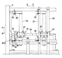
このように構成されたシート状物積載装置では、上下のシート状物を一体化させるときに、シート状物の幅方向の位置がずれていると、印刷不良、供給不良が発生するので、一体化させるときに上下のシート状物の互いの側端の位置合わせ、すなわち紙位置合わせを行っている。この紙位置合わせ手段を備えた枚葉印刷機としては、特許第22652889号公報に開示されたものがある。図12ないし図16は同公報に開示された従来の枚葉輪転印刷機の給紙積載装置を示したもので、図12は全体の概略側面図、図13は同じく紙位置合わせ装置の正面図、図14は同じく側面図、図15は同じく平面図、図16は同じく紙位置合わせ装置の下部側の側面図である。
【0004】
図12において、全体を符号1で示す枚葉輪転印刷機の給紙積載装置には、図示を省略した印刷ユニットの後方に立設された左右一対の逆L字状のフレーム2(一方は図示せず)が備えられ、その水平部材の後端部は支柱3によって床面に支持されている。4,5はスプロケットであって、左右のフレーム2に回転自在に軸支された駆動軸と従動軸とのそれぞれに軸着されている。これらスプロケット4,5に張架された昇降チェーン6,7には、後述する昇降バー40を介して方形状に形成された紙積台8が吊下され、この紙積台8には紙積板9が搭載されている。この紙積板9は方形状に形成され、上面に後述するフォーク19が挿入される前後方向(図中矢印C−D方向)に延在し、左右方向に複数条並べられた溝(図示せず)が形成され、この紙積板9上には紙10が積載されている。
【0005】
このような構成において、駆動スプロケット4の駆動軸を図示を省略したモータによって正逆方向に駆動することにより、昇降チェーン6,7を介して紙積台8が昇降(図中矢印A−B方向)するように構成されている。紙積板9上の紙10は、図示を省略したサッカ装置により上層のものから1枚ずつ吸引されて印刷ユニットに供給されるとともに、給紙により紙10が減量すると紙面を検出する図示を省略したセンサの作用で紙積台8が自動上昇するように構成されている。
【0006】
紙積台8の下方からは、レール11が後方(D方向)へ向かって床面上に敷設され、このレール11の後端部上には、予備紙積装置12が位置付けられている。この予備紙積装置12には、レール11上を走行駆動されるトロッコ13が備えられ、このトロッコ13上には、前記紙積板9と同じ紙積板9Aが搭載され、この紙積板9Aには印刷作業中に次の下側の積載紙10Aが積載される。
【0007】
この予備紙積装置12と紙積台8との間には、少量の紙を一時受けするフォーク19が設けられ、このフォーク19は紙積板9の溝と同ピッチでかつ同数設けられ、フォーク支持台18に前後方向に進退自在で、かつ昇降自在に支持されている。すなわち、フォーク支持台18を前後方向に摺動自在に支持するガイドレール17は、支柱15と昇降ガイド16とによって昇降自在に支持され、モータによって駆動される昇降チェーンによって昇降されるように構成されている。フォーク支持台18にはモータ(図示せず)が搭載され、このモータを正逆方向に回転させることにより、フォーク支持台18が矢印C−D方向に移動し、フォーク19が紙積板9の溝に挿抜されるように構成されている。このように構成されていることにより、ガイドレール17の下降状態においてフォーク支持台18が前進してフォーク19が前進すると、上昇位置にある紙積板9の溝に挿入され、少なくなっている上側の積載紙10Bを支承する。
【0008】
次に図13および図14に基づいて、フォーク19上に仮受けされている上側の積載紙10Bと下方から上昇する次の下側の積載紙10Aとの幅方向の位置を合わせる紙位置合わせ装置を説明する。
20,21は丸ステーと角ステーであって、左右のフレーム2の上端部と下端部との積載紙10Bの近傍に連結され、これらステー20,21には紙当て22が固定されている。左右のフレーム2に取り付けられた別の角ステー23と丸ステー20とは垂直バー24で連結され、この垂直バー24とフレーム2とは、水平バー25で連結されている。この水平バー25には、その上下両面に添接する上下左右4個のころ26を備えた移動部材27が、水平バー25に左右方向に移動自在に支持され、この移動部材27には検出手段移動部材としての第1のモータ28が備えられている。
【0009】
29は第1のモータ28の回転が伝達されるピニオンであって、水平バー25に固定されたラック30に噛合し、第1のモータ28が駆動されると、移動部材27が水平バー25に沿って、第13図中において実線と鎖線で示す位置の間を移動するように構成されている。31は移動部材27に固定されたストライカ、32,33はこのストライカ31の接触によって第1のモータ28を停止させ、移動部材27の両移動端限を規制するセンサA,Bとしてのリミットスイッチである。移動部材27には側面視をコ字状に形成されて上下方向に延設されたブラケット34が固定され、このブラケット34の両端部には、上側紙検知スイッチ(図示せず)を動作させる上側紙当て35と下側紙検知スイッチ(図示せず)を動作させる下側紙当て36とがそれぞれ装着されている。
【0010】
次に、図15および図16に基づいて、トロッコ13から移し替えられた紙積板9を搭載して下降位置にある紙積台8を紙10の幅方向、すなわち左右方向(図中矢印E−F方向)に移動させる構造について説明する。
昇降チェーン6,7の下端には軸受ブラケット38,38が装着され、これら軸受ブラケット38,38間には、リニアベアリングを介して昇降バー39が軸支され、この昇降バー39の両端には、昇降ガイド40a,40bに嵌合し、昇降バー39の昇降を案内するころ41,41が枢着されている。前後の軸受ブラケット38,38の下部にはころ42が枢着され、このころ42には、紙積台8の上面に固着されたガイド43が係合されて支承されることによって、紙積台8は紙10の幅方向(矢印E−F方向)に移動自在となるように支持されている。
【0011】
前後の軸受ブラケット38,38を連結する連結板44の側部には、モータベース45aを介してシート状物積載台移動手段としての第2のモータ45が固定され、この第2のモータ45のモータ軸には、ベベルギア45bが軸着され、このベベルギア45bは、モータベース45aの軸受に軸支されたねじ軸46上のベベルギア46aが噛合している。このねじ軸46は紙積台8側のブラケット8aに固定された支点ピン47のねじ孔に螺合され、第2のモータ45の駆動でねじ軸46を回転させることにより、ねじ作用で紙積台8が矢印E−F方向に移動するように構成されている。
【0012】
この第2のモータ45の回転にともなって紙積台8が左右方向に移動すると、この紙積台8とともに移動する下側の紙10Aが下側紙当て36に当接し、この当接によって第2のモータ45の回転が停止し、紙積台8の左右方向の移動が停止するように構成されている。また、上側紙検知スイッチは、フォーク19で一時受けされている上側の積載紙10Bに当接することにより上述した第1のモータ28の駆動を停止させ、上側紙当て35の移動を停止させるように構成されている。したがって、上側の積載紙10Bに当たるまで移動させた上側紙当て35と同位相の下側紙当て36に下側の紙10Aを当てることによって、上下の積載紙10B,10Aが位置合わせされるように構成されている。
【0013】
このように構成されていることにより、下側の積載紙10Aの供給時には、図13において移動部材27が左方(図中矢印E方向)に移動し、ストライカ31がセンサA32によって検出される原点位置に位置付けられている。したがって、上下の紙当て35,36も図中実線で示すように、積載紙10A,10Bから離間するように左方に移動している。一方、下側の積載紙10Aを積載した紙積台8は第2のモータ45の駆動により上下の紙当て35,36から離間する方向である右方(図中矢印F方向)に移動して停止している。この状態で駆動スプロケット4が回転し、下側の積載紙10Aを搭載した紙積台8が下側の紙当て36による検知が可能な高さまで上昇すると、第1のモータ28が回転し移動部材27が右方に移動し、上側紙当て35が上の紙10Bに近接する。
【0014】
そして、上側紙当て35が上側の積載紙10Bに接してこれを検知すると、上側紙検知スイッチが動作し、第1のモータ28が停止し上下の紙当て35,36の移動が停止する。これと同時に下側の積載紙10Aが積載された紙積台8が第2のモータ45の駆動によって移動し、下側紙当て36に接した位置でこれを検知して停止するので、上側の積載紙10Bと下側の積載紙10Aとの互いの側端が位置合わせされ紙位置合わせが完了する。紙位置合わせ作業が完了すると駆動スプロケット4がわずかに回動し、紙積台8が上昇し、上下の積載紙10B,10Aが接触した位置で停止する。図12において、フォーク支持台18を後退(図中矢印D方向に移動)させることにより、フォーク19が上下の積載紙10B,10A間から抜かれ、上下の積載紙10B,10Aが合体し、再び正規の紙供給に移行する。
【0015】
【発明が解決しようとする課題】
しかしながら、上述した従来の枚葉輪転印刷機の給紙紙積装置においては、紙位置合わせをするときに、一旦、下側の積載紙10Aを積載した紙積台8を、紙当て35,36から離間する方向である右方に移動させてから、紙検知スイッチ35,36側に移動させるようにしている。このため、紙積台8を紙当て35,36から離間する方向に移動させる間の時間を必要とし、紙位置合わせに余計に時間がかかる。したがって、特に印刷機を高速で運転する時には、この紙位置合わせにかかる余計な時間を見込んで早目のタイミングで下側の積載紙10Aを上側の積載紙10Bに接触させる必要がある。このため、1回で供給する下側の積載紙10Aの紙の量が少なくなり、その分、紙が保管されている保管倉庫から給紙紙積装置へ供給する回数が増えるため、作業者の負担が大きくなるといった問題があった。
【0016】
本発明は上記した従来の問題に鑑みなされたものであり、その目的とするところは、紙位置合わせの時間の短縮を図り、作業者の負担を軽減させた枚葉輪転印刷機のシート状物積載装置を提供することにある。
【0017】
【課題を解決するための手段】
この目的を達成するために、本発明に係る枚葉輪転印刷機のシート状物積載装置は、シート状物の供給とともに自動上昇するシート状物積載台上に積載された積載シート状物がシート状物の供給にしたがって減量したときに前記シート状物積載台と積載シート状物との間へフォークを挿入し、次の積載シート状物を積載したシート状物積載台を上昇させて次の積載シート状物と前記フォーク上の積載シート状物とを接触させ、前記フォークを抜いて正規のシート状物の供給に移行させるように構成し、前記シート状物積載台を前記積載シート状物の幅方向に移動させるシート状物積載台移動手段と、前記シート状物積載台の幅方向へ駆動される検出手段移動部材と、この検出手段移動部材に支持され前記フォーク上の上側の積載シート状物の側端の位置を検知することにより前記検出手段移動部材の移動を停止させる上側シート状物検知スイッチと、この上側シート状物検知スイッチと前記シート状物積載台の幅方向へ互いに略同位相となるように前記移動部材に支持され前記シート状物積載台上に積載された下側の積載シート状物の側端を検知する下側シート状物検知スイッチとを備えた枚葉輪転印刷機のシート状物積載装置であって、前記下側シート状物検知スイッチを、上側の積載シート状物から下側シート状物検知手段と反対側に退避した状態にある下側の積載シート状物の紙ずれを検知する第1の検知スイッチと、上側の積載シート状物から下側シート状物検知手段側に突出した状態にある下側の積載シート状物の紙ずれを検知する第2の検知スイッチとで構成するとともに、前記第1の検知スイッチまたは第2の検知スイッチの検知によって、前記シート状物積載台移動手段で前記シート状物積載台を、上側の積載シート状物に対する前記下側の積載シート状物の紙ずれに応じて前記積載シート状物の幅方向に移動させる。
したがって、まず検知手段移動部材を上側シート状物検知手段がフォーク上の上側の積載シート状物の側端の位置を検出するまで移動させ、その位置で停止させる。次に、シート状物積載台移動手段を、第1の検知スイッチが下側の積載シート状物を検知し、かつ第2の検知スイッチが下側の積載シート状物を検知しない位置まで移動させる。
【0018】
【発明の実施の形態】
以下、本発明の実施の形態を図に基づいて説明する。図1は本発明に係る枚葉輪転印刷機の給紙積載装置における紙位置合わせ装置の正面図、図2(a)は図1におけるII(a)矢視の拡大図、(b)はその平面図、図3は同じく構成図、図4は同じく紙位置合わせの動作を説明するためのフローチャート図、図5は同じく紙位置合わせの動作を説明するためのモデル図である。
これらの図において、上述した図12ないし図16に示す従来技術において説明した構成と同一または同等の部材については、同一の符号を付し詳細な説明は適宜省略する。
【0019】
本発明が上述した従来技術と異なる点は、下側の積載紙10Aの側端を、第1のセンサ54および第2のセンサ56の2個のセンサで検知するようにした点にある。すなわち、図2において、50は第1のホルダであって、ブラケット34の下端部に直交するように固定され、この第1のホルダ50には、段付きでかつ先端にねじ部が形成されたピン52を介して第2のホルダ51が、ピン52のねじ部にナット53を螺合させることにより固定されている。第1のホルダ50の長孔(図示せず)には、第1のセンサ54がナット55によって固定され、第2のホルダ51の孔(図示せず)には、第2のセンサ56がナット57によって固定されている。
【0020】
紙当て36はピン52の周りを揺動自在に支持され、ねじりコイルばね52aによって同図(b)中反時計方向に回動するように付勢されており、第1および第2のセンサ54,56によって検出される第1の被検出部36aおよび第2の被検出部36bが設けられている。この紙当て36は常時は実線で示す状態に位置付けられ、この位置では両被検出部36a,36bがともに両センサ54,56に検出されないように構成されている。この状態から、紙当て36に下側の積載紙10Aが接触し、ねじりコイルばね52aの付勢力に抗して時計方向に回動すると、まず第1の被検出部36aが第1のセンサ54に検出され、さらに時計方向に回動すると、第2の被検出部36bが第2のセンサ56に検出されるように構成されている。図1において、58は第3のセンサであって、紙当て35が上側の積載紙10Bに接触したことを検知するものである。
【0021】
そして、下側の積載紙10Aが上側の積載紙10Bの側端から第2のセンサ56側の側端に突出した図5(a)に示す状態にある場合、第3のセンサ58が上側の積載紙10Bの側端を検出した状態とする。この状態において、下側の積載紙10Aを第2のセンサ56と反対側(矢印F方向)に移動させ、第2のセンサ56による下側の積載紙10Aの側端の検出が解除された図5(b)に示す状態のときに、下側の積載紙10Aが上側の積載紙10Bと紙位置合わせされるように、第2のセンサ56が位置付けられている。換言すれば、第2のセンサ56は、上側の積載紙10Bの側端から第2のセンサ56側に突出した状態にある下側の積載紙10Aの側端の紙合わせ位置を検知するものである。
【0022】
また、下側の積載紙10Aの側端が上側の積載紙10Bの側端から第1のセンサ54と反対側に退避した図5(c)に示す状態にある場合、第3のセンサ58が上側の積載紙10Bを検出した状態とする。この状態において、下側の積載紙10Aを第1のセンサ54側(矢印E方向)に移動させ、第1のセンサ54によって下側の積載紙10Aの側端を検出した図5(d)に示す状態のときに、下側の積載紙10Aが上側の積載紙10Bと紙位置合わせされるように、第1のセンサ54が位置付けられている。換言すれば、第1のセンサ54は、上側の積載紙10Bから第1のセンサ54と反対側に退避した状態にある下側の積載紙10Aの紙合わせ位置を検知するものである。すなわち、下側の積載紙10Aは、第1のセンサ54による検出位置と第2のセンサ56による検出の解除位置との間(これを以下、許容範囲と称する)に位置していれば、上側の積載紙10Bとの位置合わせが完了したと判断されるように構成されている。
【0023】
この許容範囲は、第1のセンサ54と第2のセンサ56との間隔によって決められるもので、この間隔が狭いほど位置合わせの精度が向上する。上述したように、第1のセンサ54は、ナット55を弛めることにより、第1のホルダ50の長孔内を摺動させて位置を調整できるように構成されている。また、第2のセンサ56は、ボルト53を弛め、第2のホルダ51を第1のホルダ50に対して回動させることにより、第1のセンサ54に対する相対的な位置を調整できるように構成されており、両センサ54,56の検出位置や許容範囲を調整して紙位置合わせ精度を向上させることができる。
【0024】
図3において、59は制御装置であって、センサA32、センサB33および第3のセンサ58がONすると第1のモータ28を停止させ、第2のセンサ56がONすると第2のモータ45を逆方向に回転させるように制御する。また、第1のセンサ54がOFFのときには、第2のモータ45を正方向に回転させ、第1のセンサ54がONすると第2のモータ45を停止させるように制御する。第2のモータ45を逆方向に回転させると、下側の積載紙10Aを積載した紙積台8が第2のセンサ56から離間する方向(矢印F方向)に移動し、第2のモータ45を正方向に回転させると、紙積台8が第1、第2のセンサ54,56に近接する方向(矢印E方向)に移動するように構成されている。
【0025】
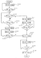
次に、このような構成の紙位置合わせ装置における紙位置合わせの動作を図4に基づいて説明する。
あらかじめ、移動部材27は、ストライカ31がセンサA32によって検出された原点位置、すなわち図1中実線で示す左側に位置付けられている。この状態からS1において、第1のモータ28が正方向に回転し、移動部材27も移動し、上側紙当て35がフォーク19に積載された上側の積載紙10Bに接触すると、S2において第3のセンサ58がONし、S3において第1のモータ28の回転が停止し、移動部材27の移動も停止する。
【0026】
このとき、S4において第2のセンサ56がONしていると、図5(a)に示すように、第3のセンサ58と第2のセンサ56との検出によって、下側の積載紙10Aの側端が上側の積載紙10Bの側端から第2のセンサ56側に突出していると制御装置59で判断する。したがって、S5において第2のモータ45を逆方向に回転させ、下側の積載紙10Aを積載した紙積台8は第2のセンサ56から離間する方向(矢印F方向)に移動させる。S6において、第2のセンサ56がONからOFFになると、図5(b)に示すように、下側の積載紙10Aと上側の積載紙10Bとの紙位置合わせが完了し、S8において第2のモータ45が停止し、紙積台8の移動も停止する。S9において第1のモータ28が逆方向に回転し、上側紙当て35が上側の積載紙10Bから離間する方向に移動部材27が移動し、S10においてストライカ31がセンサA32によって検出されると、移動部材27が原点に位置付けられたと判断し、S11において第1のモータ28の回転が停止する。
【0027】
S4において、第2のセンサ56がONしていないときには、下側の積載紙10Aが上側の積載紙10Bから第2のセンサ56側に突出していないと制御装置59で判断する。したがって、第1のセンサ54によって下側の積載紙10Aの側端が上側の積載紙10Bの側端より第1のセンサ54と離間する方向に退避しているか否かを検出する。すなわち、S7において第1のセンサ54がONしていれば、図5(b)に示すように、下側の積載紙10Aと上側の積載紙10Bとの紙位置合わせが完了していると判断し、S8において第2のモータ45の回転が停止したままの状態になっている。
【0028】
S7において、第1のセンサ54がONしていなければ、図5(c)に示すように、下側の積載紙10Aの側端が上側の積載紙10Bの側端より第1のセンサ54と離間する方向に退避していると判断し、S12において第2のモータ45を正方向に回転させる。この回転により、下側の積載紙10Aを積載した紙積台8は第1のセンサ54に接近する方向(矢印E方向)に移動する。S13において、第1のセンサ54がOFFからONになると、図5(d)に示すように、下側の積載紙10Aと上側の積載紙10Bとの紙位置合わせが完了し、S8において第2のモータ45が停止し、紙積台8の移動も停止する。
【0029】
このように本発明では、下側の積載紙10Aを検知する検知スイッチを、上側の積載紙10Bからこの検知スイッチと反対側に退避した状態にある下側の積載紙10Aの紙合わせ位置を検知する第1のセンサ54と、上側の積載紙10Bから検知スイッチ側に突出した状態にある下側の積載紙10Aの紙合わせ位置を検知する第2のセンサ56とで構成したものである。このため、従来のように、一旦退避する位置に移動させてから紙位置合わせを行う必要がなく、下側の積載紙10Aが紙積台8に載置された位置から紙合わせの動作を行うことができるので、紙位置合わせの作業時間が短縮される。また、紙位置合わせの作業時間が短縮されることにより、印刷機の高速運転時においても、この紙位置合わせ時間を考慮して早目のタイミングで下側の積載紙10Aを上側の積載紙10Bに接触させる必要がなくなる。このため、1回で供給する側の積載紙10Aの紙の供給量を多くすることができ、紙が保管されている保管倉庫から給紙紙積装置へ供給する回数が減るため、作業者の負担が軽減される。
【0030】
図6は本発明の第2の実施の形態の動作を示すフローチャートである。
この第2の実施の形態においては、紙位置合わせを行うために紙積台8を積載紙10Aの幅方向に移動させる第2のモータ45の制動機構等の故障により、第2のモータ45の停止にもかかわらず、紙積台8が紙合わせ位置に停止しないで、紙合わせ位置を越えたときに給紙を中止させるように構成したものである。すなわち、S8において第2のモータ45が停止したら、S20において第1のセンサ54がONしていれば、紙積台8が所定の紙合わせ位置に停止しているので、S9において第1のモータ28が逆方向に回転する。
【0031】
S20において第1のセンサ54がONしていないときには、紙積台8が紙合わせ位置を越えていると判断し、S21においてランプやブザー等によって異常を表示し、S22において給紙装置のフィーダーポンプ(図示せず)をOFFとする。これにより、フィーダーの吸口が紙を吸着しなくなるので、印刷機の胴が抜け空転状態となって、上下の積載紙10B,10Aの位置ずれに起因する給紙不良が防止される。同様に、S13において第1のセンサ54がONして、S23において第2のモータ45が停止しても、S24において第2のセンサ56がONしていると、紙積台8が紙合わせ位置を越えていると判断し、S21において異常を表示するように構成されている。
【0032】
図7は本発明の第3の実施の形態の動作を示すフローチャートである。
この第3の実施の形態は、下側の積載紙10Aが上側の積載紙10Bに紙位置合わせする前に既に紙位置合わせが完了している場合であっても、下側の積載紙10Aを紙位置合わせの許容範囲内の所望の位置に停止させる場合を示したものである。すなわち、S7において第1のセンサ54がONしていると、下側の積載紙10Aが上側の積載紙10Bに紙位置合わせする前に既に紙位置合わせが完了しているが、S27において第2のモータ45を正方向に回転させて、下側の積載紙10Aを故意に上側の積載紙10Bから第2のセンサ56側に突出させる。
【0033】
S28において第2のセンサ56がONしたら、図5(a)に示す状態となり、この状態となったら、S29において第2のモータ45を停止させ、S5において第2のモータ45を逆方向に回転させる。S6において第2のセンサ56がONからOFFに切り替わったら、紙位置合わせが完了したと判断して、S8において第2のモータ45が停止する。このように、下側の積載紙10Aが上側の積載紙10Bに紙位置合わせする前に既に紙位置合わせが完了している場合であっても、紙合わせ位置を許容範囲内の所望の位置に停止させることができるので、紙位置合わせの位置精度を向上させることができる。
【0034】
なお、この第3の実施の形態においては、S7において第1のセンサ54がONしたら、S27において第2のモータ45を正方向に回転させたが、逆方向に回転させてもよい。すなわち、第2のモータ45を逆方向に回転させ、第1のセンサがOFFになる図5(c)の状態とし、次にS12において第2のモータ45を正転させ、S13において第1のセンサ54がOFFからONに切り替わったら、紙位置合わせが完了したと判断して、S24において第2のモータ45が停止する。この場合にも、紙合わせ位置を許容範囲内の所望の位置に停止させることができるので、紙位置合わせの位置精度を向上させることができる。
【0035】
図8ないし図10は本発明の第4の実施の形態を示すもので、図8は枚葉輪転印刷機の給紙積載装置における紙位置合わせ装置の正面図、図9(a)は図8におけるIX(a)矢視の拡大図、(b)はその平面図、図10は同じく紙位置合わせの動作を説明するためのフローチャート図、図11は同じく紙位置合わせの動作を説明するためのモデル図である。
この第4の実施の形態が、上述した第1の実施の形態と異なる点は、上側の検知スイッチを第1のセンサ64と第2のセンサ66との2つにした点と、下側の検知スイッチを第3のセンサ68の1つにした点にある。
【0036】
すなわち、図9に示すように、ブラケット34の上端部に固定した第1のホルダ60の長孔(図示せず)には、第1のセンサ64がナット65によって固定され、第2のホルダ61は第1のホルダ60にピン62のねじ部に螺合させたナット63によって固定されている。第2のセンサ66はナット67によって第2のホルダ61に固定され、紙当て35はピン62の周りを揺動自在に支持され、ねじりコイルばね62aによって、同図(b)中反時計方向に回動するように付勢されている。35a,35bは、第1および第2のセンサ64,66によって検出される第1の被検出部および第2の被検出部であって、紙当て35は常時は実線で示す状態に位置付けられ、この位置では両被検出部35a,35bがともに両センサ64,66に検出されないように構成されている。この状態から、紙当て35に上側の積載紙10Bが接触し、ねじりコイルばね62aの付勢力に抗して時計方向に回動すると、まず第1の被検出部35aが第1のセンサ64に検出され、さらに時計方向に回動すると、第2の被検出部35bが第2のセンサ66に検出されるように構成されている。図8において、68は第3のセンサであって、紙当て35が下側の積載紙10Aに接触したことを検知するものである。
【0037】
下側の積載紙10Aが上側の積載紙10Bから第3のセンサ68側に突出した図11(a)に示す状態にある場合、移動部材27を上下の積載紙10B,10A側に移動させたときに、第1のセンサ64が上側の積載紙10Bを検知し、第2のセンサ66が上側の積載紙10Bを検知する前に、第3のセンサ68が下側の積載紙10Aを検知するように構成されている。その状態から下側の積載紙10Aを、矢印Fで示すように第3のセンサ68から離間させ、第3のセンサ68の検知が解除される図11(b)に示す状態のときに、下側の積載紙10Aが上側の積載紙10Bに紙位置合わせされるように、第1のセンサ64と第3のセンサ68とが位置付けられている。換言すれば、第1のセンサ64と第3のセンサ68との共動によって、下側の積載紙10Aが上側の積載紙10Bから第3のセンサ68側に突出した状態を検知し、第3のセンサ68によって上下の積載紙10B,10Aの紙合わせ位置を検知している。
【0038】
下側の積載紙10Aが上側の積載紙10Bから第3のセンサ68と反対側に退避した図11(c)に示す状態にある場合、移動部材27を上下の積載紙10B,10A側に移動させたときに、第1のセンサ64が上側の積載紙10Bを検知し、第3のセンサ68が下側の積載紙10Aを検知する前に、第2のセンサ66が上側の積載紙10Bを検知するように構成されている。その状態から下側の積載紙10Aを、矢印Eで示すように第3のセンサ68側に接近させ、第3のセンサ68によって検知される図11(d)に示す状態のときに、下側の積載紙10Aが上側の積載紙10Bに紙位置合わせされるように、第2のセンサ66と第3のセンサ68とが位置付けられている。換言すれば、第2のセンサ66と第3のセンサ68との共動によって、下側の積載紙10Aが上側の積載紙10Bから第3のセンサ68側に突出した状態を検知し、第3のセンサ68によって上下の積載紙10B,10Aの紙合わせ位置を検知している。
【0039】
次に、このような構成の紙合わせ装置における紙位置合わせの動作を図10に基づいて説明する。
あらかじめ、移動部材27は、ストライカ31がセンサA32によって検出された原点位置、すなわち図8中実線で示す左側に位置付けられている。この状態からS30において、第1のモータ28が正方向に回転し、移動部材27も移動し、上側紙当て35がフォーク19に積載された上側の積載紙10Bに接触すると、S31において第1のセンサ64がONする。引き続き、S32において第2のセンサ66がONする前に、S33において第3のセンサがONすると、図11(a)に示すように、下側の積載紙10Aが上側の積載紙10Bよりも第3のセンサ68側に突出していると判断する。
【0040】
S34において第1のモータ28の回転が停止し移動部材27も移動を停止し、S35において第2のモータ45が逆方向に回転し、S36において第3のセンサ68がONからOFFに切り替わると、図11(b)に示すように、下側の積載紙10Aが上側の積載紙10Bと紙位置合わせが完了する。S37において第2のモータ45の回転が停止し、S38において第1のモータ28が逆方向に回転し、S39においてセンサA32がONすると移動部材27が原点に位置し、S40において第1のモータ28の回転が停止する。
【0041】
S31において第1のセンサ64がONし、S32において第3のセンサ68がONする前に第2のセンサ66もONすると、図11(c)に示すように、下側の積載紙10Aが上側の積載紙10Bよりも第3のセンサ68と反対側の退避した位置にあると判断する。S41において第1のモータ28の回転が停止するので、移動部材27の移動が停止し、S42において第2のモータ45が正方向に回転し、下側の積載紙10Aが第3のセンサ68側に移動する。S43において第3センサ68がONすると、図11(d)に示すように、下側の積載紙10Aが上側の積載紙10Bと紙位置合わせが完了し、S37において第2のモータ45の回転が停止する。
【0042】
このように、この第4の実施の形態においても、上述した第1の実施の形態と同様に、従来のように、一旦退避する位置に移動させてから紙位置合わせの動作を行うことなく、下側の積載紙10Aが紙積台8に載置された位置から紙位置合わせの動作を行うことができるので、紙位置合わせの作業時間が短縮される。また、紙位置合わせの作業時間が短縮されることにより、印刷機の高速運転時においても、この紙位置合わせ時間を考慮して早目のタイミングで下側の積載紙10Aを上側の積載紙10Bに接触させる必要がなくなる。したがって、1回で供給する側の積載紙10Aの紙の供給量を多くすることができる。
【0043】
なお、本実施の形態では、シート状物を紙10としたが、塩化ビニールシートやフィルム等でもよく種々の選択が可能である。
【0044】
【発明の効果】
以上説明したように請求項1および請求項2記載の発明によれば、紙位置合わせの作業時間が短縮されるとともに、1回で供給する側の積載シート状物の供給量を多くすることができ、作業者の負担が軽減される。
【0045】
また、請求項3記載の発明によれば、第1および第2のセンサの検出位置や許容範囲を調整して紙位置合わせ精度を向上させることができる。
【図面の簡単な説明】
【図1】 本発明に係る枚葉輪転印刷機の給紙積載装置における紙位置合わせ装置の正面図である。
【図2】 (a)は図1におけるII(a)矢視の拡大図、(b)はその平面図である。
【図3】 本発明に係る枚葉輪転印刷機の給紙積載装置の構成図である。
【図4】 本発明に係る枚葉輪転印刷機の給紙積載装置における紙位置合わせの動作を説明するためのフローチャート図である。
【図5】 本発明に係る枚葉輪転印刷機の給紙積載装置における紙位置合わせの動作を説明するためのモデル図である。
【図6】 本発明に係る枚葉輪転印刷機の給紙積載装置の第2の実施の形態における紙位置合わせの動作を説明するためのフローチャート図である。
【図7】 本発明に係る枚葉輪転印刷機の給紙積載装置の第3の実施の形態における紙位置合わせの動作を説明するためのフローチャート図である。
【図8】 本発明に係る枚葉輪転印刷機の給紙積載装置の第4の実施の形態における紙位置合わせ装置の正面図である。
【図9】 (a)は図8におけるIX(a)矢視の拡大図、(b)はその平面図である。
【図10】 本発明に係る枚葉輪転印刷機の給紙積載装置の第4の実施の形態における紙位置合わせの動作を説明するためのフローチャート図である。
【図11】 本発明に係る枚葉輪転印刷機の給紙積載装置の第4の実施の形態における紙位置合わせの動作を説明するためのモデル図である。
【図12】 従来の枚葉輪転印刷機の給紙紙積装置における紙位置合わせ装置の全体の概略側面図である。
【図13】 従来の枚葉輪転印刷機の給紙積載装置における紙位置合わせ装置の正面図である。
【図14】 従来の枚葉輪転印刷機の給紙積載装置における紙位置合わせ装置の側面図である。
【図15】 従来の枚葉輪転印刷機の給紙積載装置における紙位置合わせ装置の平面図である。
【図16】 従来の枚葉輪転印刷機の給紙積載装置における紙位置合わせ装置の下部側の側面図である。
【符号の説明】
1…枚葉輪転印刷機の給紙積載装置、8…紙積台、10A…下側の積載紙、10B…上側の積載紙、19…フォーク、27…移動部材、28…第1のモータ、32…センサA、35,36…紙当て、45…第2のモータ、54,64…第1のセンサ、56,66…第2のセンサ、58,68…第3のセンサ、59…制御装置。
[0001]
BACKGROUND OF THE INVENTION
The present invention relates to a sheet material stacking apparatus for stacking sheet materials to be supplied to a printing unit in a sheet-fed rotary printing press, and in particular, when the stacked sheet materials are reduced by supply, The present invention relates to a sheet-shaped material stacking apparatus that can supply the next sheet-shaped material without stopping the machine.
[0002]
[Prior art]
This type of sheet stacker includes a spare sheet stacker for stacking the next sheet while the sheet is being supplied, the sheet being supplied, and the sheet on which the sheet is stacked. And a fork to be inserted between the object stacking bases. Then, when the sheet-like material is reduced according to the supply, the fork is inserted and the supply is continued while temporarily receiving the sheet-like material. The upper end of the sheet is brought into contact with the lower end of the stacked sheet-like object on the fork, and then the fork is pulled out to shift to the regular sheet-like object supply.
[0003]
In the sheet-like material stacking device configured as described above, when the upper and lower sheet-like materials are integrated, if the sheet-like material is displaced in the width direction, printing defects and supply failures occur. When the sheet is made, the side edges of the upper and lower sheet-like materials are aligned, that is, the paper is aligned. As a sheet-fed printing press provided with this paper alignment means, there is one disclosed in Japanese Patent No. 22652889. FIGS. 12 to 16 show a sheet stacking device of a conventional sheet-fed rotary printing machine disclosed in the publication, FIG. 12 is a schematic side view of the whole, and FIG. 13 is a front view of the paper alignment device. 14 is a side view, FIG. 15 is a plan view, and FIG. 16 is a side view of the lower side of the paper alignment apparatus.
[0004]
In FIG. 12, the sheet stacking apparatus of the sheet-fed rotary printing press denoted as a whole by reference numeral 1 includes a pair of left and right inverted L-shaped frames 2 (one is a figure) (Not shown), and the rear end of the horizontal member is supported on the floor surface by the support 3. Reference numerals 4 and 5 denote sprockets, which are respectively attached to a drive shaft and a driven shaft that are rotatably supported by the left and right frames 2. A paper stack 8 formed in a square shape is suspended from the lift chains 6 and 7 stretched around the sprockets 4 and 5 via a lift bar 40 which will be described later. A plate 9 is mounted. This paper stacking plate 9 is formed in a square shape, and extends in the front-rear direction (in the direction of arrow CD in the figure) in which a fork 19 described later is inserted on the upper surface, and a plurality of grooves (not shown) arranged in the left-right direction. The paper 10 is stacked on the paper stacking plate 9.
[0005]
In such a configuration, by driving the drive shaft of the drive sprocket 4 in the forward and reverse directions by a motor (not shown), the paper stack 8 is moved up and down via the lift chains 6 and 7 (in the direction of arrows AB in the figure). ) Is configured to. The paper 10 on the paper stacking plate 9 is sucked one by one from the upper layer by a sucker device (not shown) and supplied to the printing unit, and the paper surface is detected when the paper 10 is reduced by paper feeding. The paper platform 8 is automatically raised by the action of the sensor.
[0006]
A rail 11 is laid on the floor from the lower side of the paper stack 8 toward the rear (D direction), and a preliminary paper stacking device 12 is positioned on the rear end of the rail 11. The spare paper stacking device 12 is provided with a trolley 13 that is driven to run on the rail 11, and on this trolley 13, a paper stacking plate 9A that is the same as the paper stacking plate 9 is mounted. Is loaded with the next lower loaded paper 10A during the printing operation.
[0007]
A fork 19 that temporarily receives a small amount of paper is provided between the preliminary paper stacking device 12 and the paper stacking base 8. The forks 19 are provided at the same pitch and the same number as the grooves of the paper stacking plate 9. It is supported by the support base 18 so as to be movable back and forth in the front-rear direction and freely movable up and down. That is, the guide rail 17 that supports the fork support base 18 so as to be slidable in the front-rear direction is supported by the support column 15 and the elevating guide 16 so as to be movable up and down, and is configured to be raised and lowered by a lifting chain driven by a motor. ing. A motor (not shown) is mounted on the fork support base 18, and by rotating the motor in the forward and reverse directions, the fork support base 18 moves in the direction of the arrow CD, and the fork 19 is attached to the paper stack 9. It is configured to be inserted into and removed from the groove. By being configured in this way, when the fork support base 18 moves forward and the fork 19 moves forward in the lowered state of the guide rail 17, it is inserted into the groove of the paper stack 9 in the raised position, and the lower upper side The loaded paper 10B is supported.
[0008]
Next, based on FIG. 13 and FIG. 14, a paper alignment device that aligns the widthwise position of the upper stacked paper 10 </ b> B temporarily received on the fork 19 and the next lower stacked paper 10 </ b> A rising from below. Will be explained.
Reference numerals 20 and 21 denote round stays and corner stays, which are connected to the vicinity of the stacked paper 10 </ b> B at the upper and lower ends of the left and right frames 2, and a paper pad 22 is fixed to these stays 20 and 21. Another corner stay 23 and the round stay 20 attached to the left and right frames 2 are connected by a vertical bar 24, and the vertical bar 24 and the frame 2 are connected by a horizontal bar 25. The horizontal bar 25 is supported by a moving member 27 having four upper, lower, left and right rollers 26 attached to the upper and lower surfaces of the horizontal bar 25 so as to be movable in the left-right direction. A first motor 28 is provided as a member.
[0009]
Reference numeral 29 denotes a pinion to which the rotation of the first motor 28 is transmitted. The pinion 29 meshes with the rack 30 fixed to the horizontal bar 25, and when the first motor 28 is driven, the moving member 27 moves to the horizontal bar 25. Along this, it is configured to move between positions indicated by solid lines and chain lines in FIG. 31 is a striker fixed to the moving member 27, and 32 and 33 are limit switches as sensors A and B for restricting both moving ends of the moving member 27 by stopping the first motor 28 by contact of the striker 31. is there. Brackets 34 that are formed in a U shape in a side view and extend in the vertical direction are fixed to the moving member 27, and an upper paper detection switch (not shown) is operated at both ends of the bracket 34. A paper pad 35 and a lower paper pad 36 for operating a lower paper detection switch (not shown) are mounted.
[0010]
Next, based on FIG. 15 and FIG. 16, the paper stacking plate 9 transferred from the truck 13 is mounted and the paper stacking table 8 in the lowered position is placed in the width direction of the paper 10, that is, the left-right direction (arrow E in the figure). The structure to be moved in the (−F direction) will be described.
Bearing brackets 38 and 38 are attached to the lower ends of the elevating chains 6 and 7, and an elevating bar 39 is pivotally supported between the bearing brackets 38 and 38 via linear bearings. Rollers 41 and 41 that are fitted into the lifting guides 40a and 40b and guide the lifting and lowering of the lifting bar 39 are pivoted. Rollers 42 are pivotally attached to lower portions of the front and rear bearing brackets 38, 38. A guide 43 fixed to the upper surface of the paper stack 8 is engaged with and supported by the rollers 42. 8 is supported so as to be movable in the width direction (arrow EF direction) of the paper 10.
[0011]
A second motor 45 serving as a sheet-like material stacking table moving means is fixed to a side portion of the connecting plate 44 that connects the front and rear bearing brackets 38, 38 via a motor base 45a. A bevel gear 45b is attached to the motor shaft, and the bevel gear 45b meshes with a bevel gear 46a on a screw shaft 46 that is supported by a bearing of the motor base 45a. The screw shaft 46 is screwed into a screw hole of a fulcrum pin 47 fixed to the bracket 8 a on the paper stacking table 8 side, and the screw shaft 46 is rotated by driving the second motor 45, so The base 8 is configured to move in the direction of arrow EF.
[0012]
When the paper stack 8 moves in the left-right direction along with the rotation of the second motor 45, the lower paper 10A that moves together with the paper stack 8 contacts the lower paper pad 36. The rotation of the second motor 45 is stopped, and the horizontal movement of the paper stack 8 is stopped. Further, the upper paper detection switch abuts on the upper stacked paper 10 </ b> B temporarily received by the fork 19, thereby stopping the driving of the first motor 28 and stopping the movement of the upper paper pad 35. It is configured. Therefore, the upper and lower stacked paper sheets 10B and 10A are aligned by applying the lower paper sheet 10A to the lower paper pad 36 in the same phase as the upper paper pad 35 moved until it hits the upper stacked paper sheet 10B. It is configured.
[0013]
With this configuration, when the lower stacked paper 10A is supplied, the moving member 27 moves leftward (in the direction of arrow E in FIG. 13) in FIG. 13, and the striker 31 is detected by the sensor A32. Is positioned. Therefore, the upper and lower paper pads 35 and 36 are also moved to the left so as to be separated from the stacked paper 10A and 10B, as indicated by solid lines in the drawing. On the other hand, the paper stack 8 on which the lower stacked paper 10A is loaded moves to the right (in the direction of arrow F in the figure), which is the direction away from the upper and lower paper pads 35, 36, by driving the second motor 45. It has stopped. When the drive sprocket 4 rotates in this state and the paper stack 8 on which the lower stacking paper 10A is loaded rises to a height that can be detected by the lower paper pad 36, the first motor 28 rotates to move the moving member. 27 moves to the right, and the upper paper pad 35 approaches the upper paper 10B.
[0014]
When the upper paper pad 35 comes into contact with the upper stacked paper sheet 10B and detects this, the upper paper sheet detection switch operates, the first motor 28 stops, and the movement of the upper and lower paper pads 35 and 36 stops. At the same time, the paper stack 8 on which the lower loaded paper 10A is loaded is moved by the drive of the second motor 45, and is detected and stopped at a position in contact with the lower paper pad 36. The side edges of the stacked paper 10B and the lower stacked paper 10A are aligned to complete the paper alignment. When the paper alignment operation is completed, the drive sprocket 4 is slightly rotated, the paper stack 8 is raised, and stops at the position where the upper and lower stacked paper 10B and 10A are in contact. In FIG. 12, by moving the fork support base 18 backward (moving in the direction of arrow D in the figure), the fork 19 is pulled out from between the upper and lower stacked papers 10B and 10A, and the upper and lower stacked papers 10B and 10A are united, and again normal Shift to paper supply.
[0015]
[Problems to be solved by the invention]
However, in the conventional sheet-fed paper stacking device of the above-described sheet-fed rotary printing press, when paper alignment is performed, the paper stacking table 8 on which the lower stacking paper 10A is once loaded is used as the paper pads 35 and 36. Is moved to the right, which is a direction away from the paper, and then moved to the paper detection switches 35 and 36 side. For this reason, it takes time to move the paper stack 8 in the direction away from the paper pads 35 and 36, and extra time is required for paper alignment. Therefore, particularly when the printing press is operated at a high speed, it is necessary to allow the lower stacked paper 10A to contact the upper stacked paper 10B at an early timing in view of the extra time required for the paper alignment. For this reason, the amount of the lower stacked paper 10A to be supplied at one time is reduced, and the number of times the paper is supplied from the storage warehouse where the paper is stored to the paper supply device is increased. There was a problem of increasing the burden.
[0016]
The present invention has been made in view of the above-described conventional problems, and an object of the present invention is to provide a sheet-like material for a sheet-fed rotary printing press in which the time for paper alignment is shortened and the burden on the operator is reduced. It is to provide a loading device.
[0017]
[Means for Solving the Problems]
In order to achieve this object, the sheet-like material stacking apparatus of the sheet-fed rotary printing press according to the present invention is configured such that the loaded sheet-like material loaded on the sheet-like material loading table that automatically rises as the sheet-like material is supplied is a sheet. When the weight is reduced in accordance with the supply of the sheet, a fork is inserted between the sheet-shaped sheet loading table and the loaded sheet-shaped object, and the sheet-shaped sheet loading table on which the next sheet-shaped sheet is loaded is raised to The stacked sheet-like material is brought into contact with the stacked sheet-like material on the fork, and the fork is pulled out to shift to supply of a regular sheet-like material, and the sheet-shaped material stacking base is configured to be the stacked sheet-like material. Sheet-like material stacking table moving means for moving in the width direction of the sheet-like material, detecting means moving member driven in the width direction of the sheet-like material stacking table, and an upper stacked sheet on the fork supported by the detecting means moving member Like An upper sheet-like object detection switch that stops the movement of the detection means moving member by detecting the end position, and the upper sheet-like object detection switch and the sheet-like object stacking table are substantially in phase with each other in the width direction. In this way, the sheet of the sheet-fed rotary printing press is provided with a lower sheet-like material detection switch that is supported by the moving member and detects a side edge of the lower stacked sheet material that is loaded on the sheet-like material loading table. A sheet stacking apparatus, wherein the lower sheet detection switch is retracted from the upper stack sheet to the opposite side of the lower sheet detection means. A first detection switch for detecting misalignment, and a second detection switch for detecting a paper misalignment of the lower stack sheet in a state of protruding from the upper stack sheet to the lower sheet detection means side When configured with In addition, when the first detection switch or the second detection switch is detected, the sheet-like object stacking means is moved by the sheet-like object loading table moving means so that the lower sheet-like object is stacked on the upper sheet-like object. The sheet is moved in the width direction according to the paper misalignment.
Accordingly, the detecting means moving member is first moved until the upper sheet detecting means detects the position of the side edge of the upper stacked sheet on the fork, and is stopped at that position. Next, the sheet-like material loading table moving means is moved to a position where the first detection switch detects the lower stacked sheet-like material and the second detection switch does not detect the lower stacked sheet-like material. .
[0018]
DETAILED DESCRIPTION OF THE INVENTION
Hereinafter, embodiments of the present invention will be described with reference to the drawings. FIG. 1 is a front view of a paper alignment apparatus in a paper stacking apparatus of a sheet-fed rotary printing press according to the present invention, FIG. 2 (a) is an enlarged view taken along arrow II (a) in FIG. 1, and FIG. 3 is a configuration diagram, FIG. 4 is a flowchart for explaining the paper alignment operation, and FIG. 5 is a model diagram for explaining the paper alignment operation.
In these figures, FIG. 12 to FIG. 16 The same or equivalent members as those described in the prior art shown in FIG.
[0019]
The present invention is different from the above-described conventional technique in that the side edge of the lower loaded paper 10 </ b> A is detected by two sensors, the first sensor 54 and the second sensor 56. That is, in FIG. 2, reference numeral 50 denotes a first holder, which is fixed so as to be orthogonal to the lower end portion of the bracket 34. The first holder 50 is stepped and has a threaded portion at the tip. The second holder 51 is fixed by screwing the nut 53 into the threaded portion of the pin 52 via the pin 52. A first sensor 54 is fixed to a long hole (not shown) of the first holder 50 by a nut 55, and a second sensor 56 is nut to a hole (not shown) of the second holder 51. It is fixed by 57.
[0020]
The paper pad 36 is swingably supported around the pin 52 and is urged to rotate counterclockwise in FIG. 5B by a torsion coil spring 52a. , 56 is provided with a first detected portion 36a and a second detected portion 36b. The paper pad 36 is always positioned in a state indicated by a solid line, and at this position, both the detected parts 36a and 36b are not detected by both the sensors 54 and 56. From this state, when the lower loaded paper 10A comes into contact with the paper pad 36 and rotates clockwise against the urging force of the torsion coil spring 52a, the first detected portion 36a is first moved to the first sensor 54. And the second detected portion 36b is detected by the second sensor 56 when it is further rotated clockwise. In FIG. 1, 58 is a third sensor, which detects that the paper pad 35 has come into contact with the upper stacked paper 10B.
[0021]
When the lower loaded paper 10A is in the state shown in FIG. 5A in which the lower loaded paper 10A protrudes from the side edge of the upper loaded paper 10B to the side edge on the second sensor 56 side, the third sensor 58 is on the upper side. It is assumed that the side edge of the loaded paper 10B is detected. In this state, the lower stacked paper 10A is moved to the opposite side (arrow F direction) from the second sensor 56, and the detection of the side edge of the lower stacked paper 10A by the second sensor 56 is released. In the state shown in FIG. 5B, the second sensor 56 is positioned so that the lower stacked paper 10A is aligned with the upper stacked paper 10B. In other words, the second sensor 56 detects the paper alignment position of the side edge of the lower stacked paper 10A in a state protruding from the side edge of the upper stacked paper 10B to the second sensor 56 side. is there.
[0022]
In the state shown in FIG. 5C in which the side edge of the lower loaded paper 10A is retracted from the side edge of the upper loaded paper 10B to the opposite side of the first sensor 54, the third sensor 58 is It is assumed that the upper stack paper 10B has been detected. In this state, the lower stacked paper 10A is moved to the first sensor 54 side (in the direction of arrow E), and the side edge of the lower stacked paper 10A is detected by the first sensor 54 in FIG. In the state shown, the first sensor 54 is positioned so that the lower loaded paper 10A is aligned with the upper loaded paper 10B. In other words, the first sensor 54 detects a paper alignment position of the lower stacked paper 10 </ b> A that is retracted from the upper stacked paper 10 </ b> B to the opposite side of the first sensor 54. That is, if the lower stacked paper 10A is positioned between the detection position by the first sensor 54 and the detection release position by the second sensor 56 (hereinafter referred to as an allowable range), It is configured that it is determined that the alignment with the loaded paper 10B is completed.
[0023]
This allowable range is determined by the interval between the first sensor 54 and the second sensor 56, and the accuracy of alignment improves as the interval decreases. As described above, the first sensor 54 is configured to be able to adjust the position by sliding the inside of the long hole of the first holder 50 by loosening the nut 55. Further, the second sensor 56 can adjust the relative position with respect to the first sensor 54 by loosening the bolt 53 and rotating the second holder 51 with respect to the first holder 50. Thus, the paper positioning accuracy can be improved by adjusting the detection positions and allowable ranges of the sensors 54 and 56.
[0024]
In FIG. 3, 59 is a control device, which stops the first motor 28 when the sensor A32, the sensor B33 and the third sensor 58 are turned ON, and reverses the second motor 45 when the second sensor 56 is turned ON. Control to rotate in the direction. When the first sensor 54 is OFF, the second motor 45 is rotated in the forward direction, and when the first sensor 54 is turned ON, the second motor 45 is controlled to stop. When the second motor 45 is rotated in the reverse direction, the paper stack 8 on which the lower stacked paper 10 </ b> A is loaded moves in a direction away from the second sensor 56 (arrow F direction), and the second motor 45. Is rotated in the forward direction, the paper stack 8 is configured to move in a direction (arrow E direction) close to the first and second sensors 54 and 56.
[0025]
Next, the paper alignment operation in the paper alignment apparatus having such a configuration will be described with reference to FIG.
The moving member 27 is positioned in advance on the origin position where the striker 31 is detected by the sensor A32, that is, on the left side indicated by the solid line in FIG. From this state, in S1, the first motor 28 rotates in the forward direction, the moving member 27 also moves, and when the upper paper pad 35 comes into contact with the upper stacked paper 10B stacked on the fork 19, the third motor S3 in S2. The sensor 58 is turned ON, the rotation of the first motor 28 is stopped in S3, and the movement of the moving member 27 is also stopped.
[0026]
At this time, if the second sensor 56 is turned on in S4, as shown in FIG. 5A, the detection of the lower loaded paper 10A is detected by the third sensor 58 and the second sensor 56. The control device 59 determines that the side edge protrudes from the side edge of the upper stacked paper 10B toward the second sensor 56 side. Therefore, in S5, the second motor 45 is rotated in the reverse direction, and the paper stack 8 on which the lower stacked paper 10A is loaded is moved in the direction away from the second sensor 56 (arrow F direction). When the second sensor 56 is turned from ON to OFF in S6, as shown in FIG. 5B, the paper alignment between the lower stacked paper 10A and the upper stacked paper 10B is completed. The motor 45 stops, and the movement of the paper stack 8 also stops. In S9, the first motor 28 rotates in the reverse direction, and the moving member 27 moves in a direction in which the upper paper pad 35 is separated from the upper stacked paper 10B. When the striker 31 is detected by the sensor A32 in S10, the movement is performed. It is determined that the member 27 is positioned at the origin, and the rotation of the first motor 28 is stopped in S11.
[0027]
In S4, when the second sensor 56 is not ON, the controller 59 determines that the lower stacked paper 10A does not protrude from the upper stacked paper 10B to the second sensor 56 side. Therefore, the first sensor 54 detects whether or not the side edge of the lower stacked paper 10A is retracted in the direction away from the first sensor 54 from the side edge of the upper stacked paper 10B. That is, if the first sensor 54 is ON in S7, it is determined that the paper alignment between the lower stacked paper 10A and the upper stacked paper 10B is completed as shown in FIG. In S8, the rotation of the second motor 45 is stopped.
[0028]
If the first sensor 54 is not ON in S7, as shown in FIG. 5C, the side edge of the lower stacked paper 10A is closer to the first sensor 54 than the side edge of the upper stacked paper 10B. In step S12, the second motor 45 is rotated in the forward direction. By this rotation, the paper stack 8 on which the lower stacked paper 10 </ b> A is loaded moves in a direction approaching the first sensor 54 (arrow E direction). In S13, when the first sensor 54 is turned from OFF to ON, as shown in FIG. 5D, the paper alignment between the lower stacked paper 10A and the upper stacked paper 10B is completed, and in S8, the second sensor 54 is turned on. The motor 45 stops, and the movement of the paper stack 8 also stops.
[0029]
As described above, in the present invention, the detection switch for detecting the lower stacked paper 10A is detected from the upper stacked paper 10B in the state where the lower stacked paper 10A is retracted to the opposite side of the detection switch. The first sensor 54 and the second sensor 56 that detects the sheet alignment position of the lower stacked paper 10A that is protruding from the upper stacked paper 10B to the detection switch side. For this reason, unlike the conventional case, it is not necessary to perform the paper alignment after the paper is once moved to the retracted position, and the paper alignment operation is performed from the position where the lower stacked paper 10A is placed on the paper stacking base 8. Therefore, the work time for paper alignment is shortened. Further, by reducing the paper alignment work time, the lower stacked paper 10A is replaced with the upper stacked paper 10B at an early timing in consideration of the paper alignment time even during high-speed operation of the printing press. There is no need to contact the For this reason, it is possible to increase the paper supply amount of the loaded paper 10A on the supply side at one time, and the number of times of supply from the storage warehouse where the paper is stored to the paper supply device is reduced. The burden is reduced.
[0030]
FIG. 6 is a flowchart showing the operation of the second embodiment of the present invention.
In the second embodiment, due to a failure of the braking mechanism or the like of the second motor 45 that moves the paper stack 8 in the width direction of the stacked paper 10A in order to perform paper alignment, the second motor 45 In spite of the stop, the paper stacking table 8 does not stop at the paper alignment position, but is configured to stop paper feeding when the paper alignment position is exceeded. That is, when the second motor 45 is stopped in S8, if the first sensor 54 is turned on in S20, the paper stack 8 is stopped at a predetermined paper alignment position. Therefore, in S9, the first motor is stopped. 28 rotates in the opposite direction.
[0031]
When the first sensor 54 is not ON in S20, it is determined that the paper stack 8 has exceeded the paper alignment position, an abnormality is displayed by a lamp, a buzzer, or the like in S21, and the feeder pump of the paper feeder in S22 (Not shown) is turned OFF. As a result, the feeder's suction port does not adsorb the paper, and the cylinder of the printing press comes out and idles, thereby preventing a paper feed failure caused by the positional deviation between the upper and lower stacked paper 10B and 10A. Similarly, even if the first sensor 54 is turned on in S13 and the second motor 45 is stopped in S23, if the second sensor 56 is turned on in S24, the paper stack 8 is in the paper alignment position. It is determined that it exceeds the limit, and an abnormality is displayed in S21.
[0032]
FIG. 7 is a flowchart showing the operation of the third embodiment of the present invention.
In the third embodiment, even when the paper alignment is already completed before the lower stacked paper 10A is aligned with the upper stacked paper 10B, the lower stacked paper 10A is removed. This shows a case of stopping at a desired position within an allowable range of paper alignment. That is, if the first sensor 54 is turned on in S7, the paper alignment is already completed before the lower stacked paper 10A is aligned with the upper stacked paper 10B. The motor 45 is rotated in the forward direction to intentionally cause the lower stacked paper 10A to project from the upper stacked paper 10B to the second sensor 56 side.
[0033]
When the second sensor 56 is turned on in S28, the state shown in FIG. 5A is obtained. In this state, the second motor 45 is stopped in S29, and the second motor 45 is rotated in the reverse direction in S5. Let If the second sensor 56 is switched from ON to OFF in S6, it is determined that the paper alignment has been completed, and the second motor 45 is stopped in S8. As described above, even when the paper alignment is completed before the lower stacked paper 10A is aligned with the upper stacked paper 10B, the paper alignment position is set to a desired position within the allowable range. Since it can be stopped, the positional accuracy of the paper alignment can be improved.
[0034]
In the third embodiment, when the first sensor 54 is turned on in S7, the second motor 45 is rotated in the forward direction in S27, but it may be rotated in the reverse direction. That is, the second motor 45 is rotated in the reverse direction to the state shown in FIG. 5C in which the first sensor is turned off. Next, in S12, the second motor 45 is rotated forward, and in S13, the first motor is rotated forward. Sensor 54 Is switched from OFF to ON, it is determined that the paper alignment is completed, and the second motor 45 is stopped in S24. Also in this case, since the paper alignment position can be stopped at a desired position within the allowable range, the positional accuracy of the paper alignment can be improved.
[0035]
FIGS. 8 to 10 show a fourth embodiment of the present invention. FIG. 8 is a front view of a paper aligning device in a paper stacking device of a sheet-fed rotary printing press, and FIG. IX (a) is an enlarged view taken along arrow (a), FIG. 10 is a plan view thereof, FIG. 10 is a flowchart for explaining the paper alignment operation, and FIG. 11 is also for explaining the paper alignment operation. It is a model figure.
The fourth embodiment is different from the first embodiment described above in that the upper detection switch is composed of two sensors, the first sensor 64 and the second sensor 66, and the lower one. The detection switch is one of the third sensors 68.
[0036]
That is, as shown in FIG. 9, the first sensor 64 is fixed by the nut 65 in the long hole (not shown) of the first holder 60 fixed to the upper end portion of the bracket 34, and the second holder 61. Is fixed to the first holder 60 by a nut 63 screwed into the threaded portion of the pin 62. The second sensor 66 is fixed to the second holder 61 by a nut 67, the paper pad 35 is supported so as to be swingable around the pin 62, and is counterclockwise in FIG. 5B by a torsion coil spring 62a. It is biased to rotate. 35a and 35b are a first detected part and a second detected part detected by the first and second sensors 64 and 66, and the paper pad 35 is always positioned in a state indicated by a solid line, At this position, both the detected parts 35a and 35b are configured not to be detected by both the sensors 64 and 66. From this state, when the upper stacked paper 10B comes into contact with the paper pad 35 and rotates clockwise against the urging force of the torsion coil spring 62a, the first detected portion 35a first contacts the first sensor 64. When detected and further rotated clockwise, the second detected portion 35b is detected by the second sensor 66. In FIG. 8, reference numeral 68 denotes a third sensor, which detects that the paper pad 35 has come into contact with the lower loaded paper 10A.
[0037]
In the state shown in FIG. 11A in which the lower stacked paper 10A protrudes from the upper stacked paper 10B to the third sensor 68 side, the moving member 27 is moved to the upper and lower stacked paper 10B, 10A side. Sometimes, the first sensor 64 detects the upper stacked paper 10B, and the second sensor 66 detects the upper stacked paper 10B before the third sensor 68 detects the lower stacked paper 10A. It is configured as follows. In the state shown in FIG. 11B in which the lower loaded paper 10A is separated from the third sensor 68 as indicated by the arrow F and the detection of the third sensor 68 is released. The first sensor 64 and the third sensor 68 are positioned so that the upper stacked paper 10A is aligned with the upper stacked paper 10B. In other words, the state in which the lower loaded paper 10A protrudes from the upper loaded paper 10B to the third sensor 68 side is detected by the cooperation of the first sensor 64 and the third sensor 68. The sensor 68 detects the sheet alignment position of the upper and lower stacked sheets 10B and 10A.
[0038]
In the state shown in FIG. 11C in which the lower stacked paper 10A is retracted from the upper stacked paper 10B to the opposite side of the third sensor 68, the moving member 27 is moved to the upper and lower stacked paper 10B, 10A side. When the first sensor 64 detects the upper stacked paper 10B, the second sensor 66 detects the upper stacked paper 10B before the third sensor 68 detects the lower stacked paper 10A. It is configured to detect. In this state, the lower loaded paper 10A is brought closer to the third sensor 68 side as indicated by an arrow E, and the lower side is detected in the state shown in FIG. The second sensor 66 and the third sensor 68 are positioned so that the stacked paper 10A is aligned with the upper stacked paper 10B. In other words, the state in which the lower stacked paper 10A protrudes from the upper stacked paper 10B to the third sensor 68 side is detected by the cooperation of the second sensor 66 and the third sensor 68. The sensor 68 detects the sheet alignment position of the upper and lower stacked sheets 10B and 10A.
[0039]
Next, the operation of paper alignment in the paper aligning apparatus having such a configuration will be described with reference to FIG.
The moving member 27 is positioned in advance on the origin position where the striker 31 is detected by the sensor A32, that is, on the left side indicated by the solid line in FIG. From this state, in S30, the first motor 28 rotates in the forward direction, the moving member 27 also moves, and when the upper paper pad 35 comes into contact with the upper stacked paper 10B loaded on the fork 19, the first motor is moved in S31. The sensor 64 is turned on. Subsequently, if the third sensor is turned on in S33 before the second sensor 66 is turned on in S32, as shown in FIG. 11 (a), the lower stacked paper 10A is higher than the upper stacked paper 10B. 3 is projected to the sensor 68 side.
[0040]
In S34, the rotation of the first motor 28 stops and the moving member 27 also stops moving. In S35, the second motor 45 rotates in the reverse direction. In S36, the third sensor 68 is switched from ON to OFF. As shown in FIG. 11B, the lower stacked paper 10A is aligned with the upper stacked paper 10B. In S37, the rotation of the second motor 45 is stopped. In S38, the first motor 28 is rotated in the reverse direction. When the sensor A32 is turned on in S39, the moving member 27 is located at the origin. In S40, the first motor 28 is rotated. Stops rotating.
[0041]
When the first sensor 64 is turned on in S31 and the second sensor 66 is also turned on before the third sensor 68 is turned on in S32, the lower loaded paper 10A is placed on the upper side as shown in FIG. It is determined that it is in the retracted position on the opposite side of the third sensor 68 from the loaded paper 10B. Since the rotation of the first motor 28 is stopped in S41, the movement of the moving member 27 is stopped. In S42, the second motor 45 is rotated in the forward direction, and the lower stacked paper 10A is moved to the third sensor 68 side. Move to. When the third sensor 68 is turned on in S43, as shown in FIG. 11D, the lower stacked paper 10A is aligned with the upper stacked paper 10B, and the rotation of the second motor 45 is rotated in S37. Stop.
[0042]
As described above, in the fourth embodiment, similarly to the first embodiment described above, the paper positioning operation is not performed after the paper is once moved to the retracted position, as in the prior art. Since the paper positioning operation can be performed from the position where the lower stacked paper 10A is placed on the paper stacking base 8, the work time for paper positioning is shortened. Further, by reducing the paper alignment work time, the lower stacked paper 10A is replaced with the upper stacked paper 10B at an early timing in consideration of the paper alignment time even during high-speed operation of the printing press. There is no need to contact the Therefore, it is possible to increase the supply amount of the loaded paper 10A on the supply side at a time.
[0043]
In the present embodiment, the sheet-like material is the paper 10, but a vinyl chloride sheet, a film, or the like may be used, and various selections are possible.
[0044]
【The invention's effect】
As described above, according to the first and second aspects of the invention, the work time for paper alignment can be shortened and the supply amount of the stacked sheet-like material to be supplied at one time can be increased. This reduces the burden on the operator.
[0045]
According to the third aspect of the present invention, it is possible to improve the paper alignment accuracy by adjusting the detection positions and allowable ranges of the first and second sensors.
[Brief description of the drawings]
FIG. 1 is a front view of a paper alignment device in a paper feed stacking device of a sheet-fed rotary printing press according to the present invention.
2A is an enlarged view taken along the line II (a) in FIG. 1, and FIG. 2B is a plan view thereof.
FIG. 3 is a configuration diagram of a sheet stacking device of a sheet-fed rotary printing press according to the present invention.
FIG. 4 is a flowchart for explaining the operation of paper alignment in the paper stacking device of the sheet-fed rotary printing press according to the present invention.
FIG. 5 is a model diagram for explaining an operation of paper alignment in a paper feed stacking device of a sheet-fed rotary printing press according to the present invention.
FIG. 6 is a flowchart for explaining a paper alignment operation in the second embodiment of the sheet stacking device of the sheet-fed rotary printing press according to the present invention.
FIG. 7 is a flowchart for explaining the operation of paper alignment in the third embodiment of the sheet stacking device of the sheet-fed rotary printing press according to the present invention.
FIG. 8 is a front view of a paper alignment apparatus in a fourth embodiment of a paper feed stacking apparatus for a sheet-fed rotary printing press according to the present invention.
9A is an enlarged view taken along the line IX (a) in FIG. 8, and FIG. 9B is a plan view thereof.
FIG. 10 is a flowchart for explaining an operation of paper alignment in the fourth embodiment of the sheet stacking device of the sheet-fed rotary printing press according to the present invention.
FIG. 11 is a model diagram for explaining the operation of paper alignment in the fourth embodiment of the sheet stacking device of the sheet-fed rotary printing press according to the present invention.
FIG. 12 is a schematic side view of an entire paper alignment device in a paper feeding and stacking device of a conventional sheet-fed rotary printing press.
FIG. 13 is a front view of a paper alignment device in a paper stacking device of a conventional sheet-fed rotary printing press.
FIG. 14 is a side view of a paper alignment device in a paper feed stacking device of a conventional sheet-fed rotary printing press.
FIG. 15 is a plan view of a paper alignment device in a paper feed stacking device of a conventional sheet-fed rotary printing press.
FIG. 16 is a side view of the lower side of a paper alignment device in a paper stacking device of a conventional sheet-fed rotary printing press.
[Explanation of symbols]
DESCRIPTION OF SYMBOLS 1 ... Sheet feeding device of sheet-fed rotary printing machine, 8 ... Paper stacking board, 10A ... Lower loading paper, 10B ... Upper loading paper, 19 ... Fork, 27 ... Moving member, 28 ... First motor, 32 ... Sensor A, 35, 36 ... Paper pad, 45 ... Second motor, 54, 64 ... First sensor, 56, 66 ... Second sensor, 58, 68 ... Third sensor, 59 ... Control device .

Claims (3)

シート状物の供給とともに自動上昇するシート状物積載台上に積載された積載シート状物がシート状物の供給にしたがって減量したときに前記シート状物積載台と積載シート状物との間へフォークを挿入し、次の積載シート状物を積載したシート状物積載台を上昇させて次の積載シート状物と前記フォーク上の積載シート状物とを接触させ、前記フォークを抜いて正規のシート状物の供給に移行させるように構成し、前記シート状物積載台を前記積載シート状物の幅方向に移動させるシート状物積載台移動手段と、前記シート状物積載台の幅方向へ駆動される検出手段移動部材と、この検出手段移動部材に支持され前記フォーク上の上側の積載シート状物の側端の位置を検知することにより前記検出手段移動部材の移動を停止させる上側シート状物検知スイッチと、この上側シート状物検知スイッチと前記シート状物積載台の幅方向へ互いに略同位相となるように前記移動部材に支持され前記シート状物積載台上に積載された下側の積載シート状物の側端を検知する下側シート状物検知スイッチとを備えた枚葉輪転印刷機のシート状物積載装置において、前記下側シート状物検知スイッチを、上側の積載シート状物から下側シート状物検知手段と反対側に退避した状態にある下側の積載シート状物の紙ずれを検知する第1の検知スイッチと、上側の積載シート状物から下側シート状物検知手段側に突出した状態にある下側の積載シート状物の紙ずれを検知する第2の検知スイッチとで構成するとともに、前記第1の検知スイッチまたは第2の検知スイッチの検知によって、前記シート状物積載台移動手段で前記シート状物積載台を、上側の積載シート状物に対する前記下側の積載シート状物の紙ずれに応じて前記積載シート状物の幅方向に移動させることを特徴とする枚葉輪転印刷機のシート状物積載装置。  When the stacked sheet loaded on the sheet stack that automatically rises with the supply of the sheet decreases in accordance with the supply of the sheet, to the space between the sheet stack and the stacked sheet Insert the fork, raise the sheet loading table on which the next loaded sheet is loaded, bring the next loaded sheet into contact with the loaded sheet on the fork, remove the fork and The sheet-shaped article loading table moving means for moving the sheet-like article loading table in the width direction of the loaded sheet-shaped article, and the width direction of the sheet-like article loading table A detecting means moving member to be driven and an upper sheet supported by the detecting means moving member to stop the movement of the detecting means moving member by detecting the position of the side edge of the upper stack sheet on the fork. A sheet-shaped object detection switch, and a lower sheet loaded on the sheet-shaped object loading table supported by the moving member so as to be substantially in phase with each other in the width direction of the upper sheet-shaped object detection switch and the sheet-shaped object loading table. In a sheet-like material stacking apparatus of a sheet-fed rotary printing press provided with a lower sheet-like material detection switch for detecting a side edge of the side stacked sheet-like material, the lower sheet-like material detection switch is connected to the upper stacked sheet. A first detection switch for detecting paper misalignment of the lower stacked sheet in a state of being retracted from the sheet to the opposite side of the lower sheet detecting means, and the lower sheet from the upper stacked sheet And a second detection switch for detecting a paper misalignment of the lower stacked sheet-like material in a state protruding to the object detection means side, and detection by the first detection switch or the second detection switch, The sea The sheet loading table is moved in the width direction of the stacking sheet according to the paper misalignment of the lower loading sheet with respect to the upper loading sheet. A sheet stacking device for a sheet-fed rotary printing press. シート状物の供給とともに自動上昇するシート状物積載台上に積載された積載シート状物がシート状物の供給にしたがって減量したときに前記シート状物積載台と積載シート状物との間へフォークを挿入し、次の積載シート状物を積載したシート状物積載台を上昇させて次の積載シート状物と前記フォーク上の積載シート状物とを接触させ、前記フォークを抜いて正規のシート状物の供給に移行させるように構成し、前記シート状物積載台を前記積載シート状物の幅方向に移動させるシート状物積載台移動手段と、前記シート状物積載台の幅方向へ駆動される検知手段移動部材と、この検知手段移動部材に支持され前記フォーク上の上側の積載シート状物の側端の位置を検知する上側シート状物検知スイッチと、この上側シート状物検知スイッチと前記シート状物積載台の幅方向が互いに略同位相となるように前記移動部材に支持され前記シート状物積載台上に積載された下側の積載シート状物の側端を検知する下側シート状物検知スイッチとを備えた枚葉輪転印刷機のシート状物積載装置において、前記上側シート状物検知スイッチを第1の検知スイッチと第2の検知スイッチとで構成し、前記下側シート状物検知手段と前記第1の検知スイッチとの共動で、下側の積載シート状物が上側の積載シート状物から下側シート状物検知手段側に突出した状態にある下側の積載シート状物の紙ずれの検知を行うとともに、前記下側シート状物検知手段と前記第2検知のスイッチとの共動によって、下側の積載シート状物が上側の積載シート状物から下側シート状物検知手段と反対側に退避した状態にある下側の積載シート状物の紙ずれの検知を行うとともに、前記下側シート状物検知手段と第1の検知スイッチまたは第2の検知スイッチとの共動によって、前記シート状物積載台移動手段で前記シート状物積載台を、上側の積載シート状物に対する前記下側の積載シート状物の紙ずれに応じて前記積載シート状物の幅方向に移動させることを特徴とする枚葉輪転印刷機のシート状物積載装置。  When the stacked sheet loaded on the sheet stack that automatically rises with the supply of the sheet decreases in accordance with the supply of the sheet, to the space between the sheet stack and the stacked sheet Insert the fork, raise the sheet loading table on which the next loaded sheet is loaded, bring the next loaded sheet into contact with the loaded sheet on the fork, remove the fork and The sheet-shaped article loading table moving means for moving the sheet-like article loading table in the width direction of the loaded sheet-shaped article, and the width direction of the sheet-like article loading table A detection means moving member to be driven; an upper sheet detection switch that detects the position of the side edge of the upper stacked sheet on the fork supported by the detection means movement member; and the upper sheet detection switch. The side edge of the lower stacked sheet loaded on the sheet loaded table supported by the moving member is detected so that the width direction of the sheet and the sheet loaded table are substantially in phase with each other. In a sheet-like material stacking device of a sheet-fed rotary printing press provided with a lower sheet-like material detection switch, the upper sheet-like material detection switch includes a first detection switch and a second detection switch, and the lower A lower side in a state in which the lower stacked sheet-like material protrudes from the upper stacked sheet-like material to the lower sheet-like material detecting means by the cooperation of the side sheet-like material detecting means and the first detection switch. The sheet misalignment of the stacked sheet is detected and the lower sheet detecting means and the second detection switch cooperate to move the lower stacked sheet from the upper stacked sheet. Retreat to the opposite side of the lower sheet detection means The sheet-like material is detected by detecting the sheet misalignment of the lower stacked sheet-like material in the state of being in the closed state, and by the cooperation of the lower-side sheet-like material detecting means and the first detection switch or the second detection switch. The sheet-like material loading table is moved in the width direction of the sheet-like material in accordance with a paper shift of the lower-side loading sheet-like material with respect to the upper-side loading sheet-like material. Sheet loader for sheet-fed rotary printing presses. 請求項1または請求項2記載の枚葉輪転印刷機のシート状物積載装置において、第1の検知スイッチおよび第2の検知スイッチを、移動部材に位置調整自在に支持したことを特徴とする枚葉輪転印刷機のシート状物積載装置。  3. A sheet stacking apparatus for a sheet-fed rotary printing press according to claim 1 or 2, wherein the first detection switch and the second detection switch are supported on the moving member so as to be adjustable in position. Sheet loader for leaf rotary printing press.
JP08371998A 1998-03-30 1998-03-30 Sheet-like material stacking device for sheet-fed rotary printing press Expired - Fee Related JP3905630B2 (en)

Priority Applications (1)

Application Number Priority Date Filing Date Title
JP08371998A JP3905630B2 (en) 1998-03-30 1998-03-30 Sheet-like material stacking device for sheet-fed rotary printing press

Applications Claiming Priority (1)

Application Number Priority Date Filing Date Title
JP08371998A JP3905630B2 (en) 1998-03-30 1998-03-30 Sheet-like material stacking device for sheet-fed rotary printing press

Publications (2)

Publication Number Publication Date
JPH11278691A JPH11278691A (en) 1999-10-12
JP3905630B2 true JP3905630B2 (en) 2007-04-18

Family

ID=13810332

Family Applications (1)

Application Number Title Priority Date Filing Date
JP08371998A Expired - Fee Related JP3905630B2 (en) 1998-03-30 1998-03-30 Sheet-like material stacking device for sheet-fed rotary printing press

Country Status (1)

Country Link
JP (1) JP3905630B2 (en)

Also Published As

Publication number Publication date
JPH11278691A (en) 1999-10-12

Similar Documents

Publication Publication Date Title
JP2649842B2 (en) Sheet feeding machine for sheet-fed printing press
JP3293890B2 (en) Sheet feeder
JP3905630B2 (en) Sheet-like material stacking device for sheet-fed rotary printing press
JPS60296B2 (en) sheet feeding machine
JPS61145042A (en) Paper piling position control device for leaf printing machine
JP3727727B2 (en) Sheet feeding machine for sheet-fed printing press
JP2539341B2 (en) High stacking paper alignment device
JP2642935B2 (en) End face positioning device for sheet pile in feeder
JP2672488B2 (en) Device for supporting a residual pile of printing sheets during automatic pile change and method of operating the device
JPH0130736B2 (en)
JPH11232421A (en) Sheet number confirming device for plate
JP2876334B2 (en) Sheet feeding method and apparatus for sheet-fed printing press
JP2652889B2 (en) Sheet feeding machine for sheet-fed printing press
JP2009527431A (en) Adjustable supply / delivery board for printing press
JP2573903B2 (en) Automatic stacking reversing device
JP3134228B2 (en) Sheet feeding machine for sheet-fed printing press
CN217867109U (en) Automatic alignment fork paper device
JPH07137921A (en) Paper jogger
JPH0743092Y2 (en) Paper regulation device in paper ejection device of printing machine
JP4132748B2 (en) Sheet-fed printing machine paper discharge device
JPH0711052Y2 (en) Paper feeder for sheet-fed printing press
JPH0761818B2 (en) Paper feeder for sheet-fed printing press
JPH0641953Y2 (en) Sheet-fed press feeder
JPH01321222A (en) Feed paper stacker for sheet-fed press
JPS61145045A (en) Piling device for paper feeder in leaf printing machine

Legal Events

Date Code Title Description
A521 Written amendment

Free format text: JAPANESE INTERMEDIATE CODE: A523

Effective date: 20050224

A621 Written request for application examination

Free format text: JAPANESE INTERMEDIATE CODE: A621

Effective date: 20050224

A977 Report on retrieval

Free format text: JAPANESE INTERMEDIATE CODE: A971007

Effective date: 20061222

TRDD Decision of grant or rejection written
A01 Written decision to grant a patent or to grant a registration (utility model)

Free format text: JAPANESE INTERMEDIATE CODE: A01

Effective date: 20070109

A61 First payment of annual fees (during grant procedure)

Free format text: JAPANESE INTERMEDIATE CODE: A61

Effective date: 20070112

R150 Certificate of patent or registration of utility model

Free format text: JAPANESE INTERMEDIATE CODE: R150

FPAY Renewal fee payment (event date is renewal date of database)

Free format text: PAYMENT UNTIL: 20110119

Year of fee payment: 4

LAPS Cancellation because of no payment of annual fees