JP3905261B2 - Control device for turbocharged engine - Google Patents
Control device for turbocharged engine Download PDFInfo
- Publication number
- JP3905261B2 JP3905261B2 JP26580399A JP26580399A JP3905261B2 JP 3905261 B2 JP3905261 B2 JP 3905261B2 JP 26580399 A JP26580399 A JP 26580399A JP 26580399 A JP26580399 A JP 26580399A JP 3905261 B2 JP3905261 B2 JP 3905261B2
- Authority
- JP
- Japan
- Prior art keywords
- supercharging pressure
- diagnosis
- target
- throttle valve
- engine
- Prior art date
- Legal status (The legal status is an assumption and is not a legal conclusion. Google has not performed a legal analysis and makes no representation as to the accuracy of the status listed.)
- Expired - Lifetime
Links
Images


Classifications
-
- Y—GENERAL TAGGING OF NEW TECHNOLOGICAL DEVELOPMENTS; GENERAL TAGGING OF CROSS-SECTIONAL TECHNOLOGIES SPANNING OVER SEVERAL SECTIONS OF THE IPC; TECHNICAL SUBJECTS COVERED BY FORMER USPC CROSS-REFERENCE ART COLLECTIONS [XRACs] AND DIGESTS
- Y02—TECHNOLOGIES OR APPLICATIONS FOR MITIGATION OR ADAPTATION AGAINST CLIMATE CHANGE
- Y02T—CLIMATE CHANGE MITIGATION TECHNOLOGIES RELATED TO TRANSPORTATION
- Y02T10/00—Road transport of goods or passengers
- Y02T10/10—Internal combustion engine [ICE] based vehicles
- Y02T10/12—Improving ICE efficiencies
Description
【0001】
【発明の属する技術分野】
本発明は、排気ターボ過給機とスロットル弁開度を電子制御するスロットル制御装置とを備え、エンジン制御用にスロットル上流の過給圧(以下単に過給圧という) を推定するエンジンにおいて、異常の有無を診断する技術に関する。
【0002】
【従来の技術】
従来、スロットル弁開度を電子制御するスロットル制御装置を備えたエンジンの吸入空気量の制御装置として、例えば特開昭62−110536号等に示されるようなものがある。
【0003】
このものでは、アクセル開度とエンジン回転速度等に基づいてエンジンの目標トルクを算出し、該目標トルクとエンジン回転速度とに基づいて目標吸入空気量を得るべく目標スロットル弁開度を算出してスロットル弁を制御している。
【0004】
ところで、排気ターボ過給機を備えたエンジンで前記スロットル弁の電子制御を行う場合、運転条件の変化に応じて過給圧を変化させる過渡時には、アクセル開度やエンジン回転速度等の運転条件によって定まる平衡時の過給圧に所望の速度で達するようにスロットル弁開度を制御することで、加速フィーリングの向上など運転性能を高めることが可能である。
【0005】
また、成層燃焼と均質燃焼とを運転条件に応じて切り換えて使用するようなエンジンでは、各燃焼に対して同一のトルクを発生する過給圧が異なるため、燃焼切換時に応答性よく過給圧を切り換え、また、成層燃焼時の過渡特性を均質燃焼時と同様の特性とするためにも、過渡時の吸入空気量を補正して過給圧過渡特性を補正するようにスロットル弁開度制御を行うことが試みられている。
【0006】
【発明が解決しようとする課題】
上記のスロットル弁開度制御を実行するため、過渡時に変化する過給圧を推定し、アクセル開度やエンジン回転速度等のエンジン運転状態に基づいて設定された目標過給圧と推定された過給圧とを比較し、両者の偏差の大きさや割合に応じて目標吸入空気量を補正し、該補正された目標吸入空気量が得られるようにスロットル弁開度を制御することにより、所望の過給圧過渡特性(所望の速度で平衡過給圧に達するような特性)を得るように制御することが試みられている。なお、別のエンジン制御のため、実際の過給圧を検出するセンサを設けることが一般的であるが、例えば前記制御の場合に推定過給圧の代わりに実際の検出過給圧を用いて目標過給圧との偏差に基づいて制御を行っても、実過給圧により定まる過給圧の過渡特性は、必ずしも所望の特性にはならず、推定値を用いることで所望の過給圧過渡特性を得ることができる。
【0007】
しかしながら、このように過給圧の推定値を用いてエンジン制御を行う場合、過給系の異常や過給圧推定演算のNGなどを生じた場合には、該エンジン制御を正常に行うことができず、エンジン性能を悪化させてしまう可能性がある。具体的には、特に加速時にアクセル踏み込み量で予測されるより急激な加速(UA)を生じることが問題となる。
【0008】
本発明は、このような従来の課題に着目してなされたもので、過給圧の推定値を用いてエンジン制御を行うものにおいて、異常の有無を診断し、また、異常発生時に適切なフェイルセーフ制御が行われるようにした過給機付エンジンの制御装置を提供することを目的とする。
【0009】
【課題を解決するための手段】
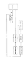
このため、請求項1に係る発明は、図1に示すように、
スロットル弁開度を目標値に電子制御するスロットル制御装置と、該スロットル弁の上流に排気ターボ過給機と、を備えた過給機付エンジンにおいて、
スロットル弁上流の過給圧をエンジン運転状態に基づいて推定する過給圧推定手段と、
スロットル弁上流の目標過給圧を設定し、該目標過給圧と前記過給圧推定手段により推定された過給圧の推定値との相違に基づいて目標吸入空気量を補正することにより、前記スロットル制御装置によるスロットル弁開度制御を介して、過給圧の過渡特性を補正制御するエンジン制御手段と、
前記スロットル弁上流の実際の過給圧を検出する過給圧検出手段と、
前記過給圧推定手段により推定された過給圧と、前記過給圧検出手段により検出された過給圧とを比較して、異常の有無を診断する診断手段と、
前記診断手段によって異常ありとの診断が下されたときは、前記エンジン制御手段における過給圧の推定値に基づく目標吸入空気量の補正を禁止するフェールセーフ手段と、
を含んで構成したことを特徴とする。
【0010】
請求項1に係る発明によると、
過給圧推定手段により推定された過給圧に基づいてエンジン制御を行いながら、過給圧検出手段によってスロットル弁上流の実際の過給圧が検出され、前記推定された過給圧と検出された過給圧とを比較して、過給機系の故障や過給圧の推定演算のNGなどの異常の有無が診断される。
【0011】
したがって、異常発生時には、推定された過給圧に基づくエンジン制御に対処することができる。
また、エンジン制御手段は、目標過給圧と過給圧の推定値との相違に基づいて、スロットル弁開度制御を介して吸入空気量が補正されることにより、過給圧の遅れを適度に抑制した所望の過給圧過渡特性を得るような制御を行え、以って、加減速時に要求に応じたトルク応答を得たり、また、均質燃焼と成層燃焼との切り換え時のトルク変化を抑制したりすることができる。
また、異常ありとの診断が下され、過給機系統の故障や過給圧推定演算のNGを生じたりしている状態では、過給圧の推定値に信頼性が無く、該推定値に基づく吸入空気量の補正を行うと、過給圧が急激に上昇して予測しない急激な加速を生じる可能性がある。そこで、このようなときには、フェールセーフ手段により、過給圧の推定値に基づく目標吸入空気量の補正を禁止することにより、前記予測しない急激な加速の発生を防止する。
また、請求項2に係る発明は、
前記診断手段は、前記過給圧の推定値と検出値との偏差が、所定値若しくは所定割合より大きいときを含む条件で異常ありとの診断を下すことを特徴とする。
【0012】
請求項2に係る発明によると、
過給圧の推定値と検出値との偏差が、所定値若しくは所定割合より大きいときは、何らかの異常により推定値が実際の過給圧から大きく外れている可能性が高いので異常ありとの診断を下すことにより、高い診断精度を確保することができる。
【0017】
また、請求項3に係る発明は、
前記診断手段によって異常ありとの診断が下されたときは、前記目標吸入空気量の補正を禁止すると共に、空燃比をリーンとする制御を禁止することを特徴とする。
【0018】
請求項3に係る発明によると、
また、異常ありとの診断が下されたときは、リーン燃焼を禁止して均質ストイキ燃焼などに切り換えることにより、燃焼の安定性を確保することができる。また、例えば、ドライバに馴染みのある均質ストイキ燃焼時の加速フィーリング(アクセル開度に対する加速特性)に近づけるようなこともできる。
【0019】
また、請求項4に係る発明は、
前記目標過給圧の補正の禁止を、目標過給圧を増大する方向の補正のみ禁止することを特徴とする。
【0020】
請求項4に係る発明によると、
減速時などに過給圧の減少が遅く実際の過給圧が推定過給圧より大きくなりすぎる結果として、異常ありとの診断が下されるようなこともありうるが、その場合に目標過給圧を減少補正して、減速を速める方向の補正を行うことは、妥当な補正である。したがって、目標過給圧を増大する方向の補正のみ禁止して、過給圧を減少させる方向の補正は許容することにより、良好な減速性能を確保する。
【0021】
また、請求項5に係る発明は、
前記診断手段は、前記過給圧検出手段が異常と診断されているときには、診断を禁止することを特徴とする。
【0022】
請求項5に係る発明によると、
過給圧検出手段が異常と診断されている場合は、過給圧の検出値との比較で行われる診断の信頼性を確保できないため、該診断を禁止することにより、診断の信頼性を確保できる。
【0023】
また、請求項6に係る発明は、
前記診断手段は、全開に近い高負荷時には、診断を禁止することを特徴とする。
【0024】
請求項6に係る発明によると、
全開に近い高負荷状態で更にアクセルを踏み込んで加速操作を行ったような場合は、実際の過給圧の検出値は十分大きい値を示し、推定過給圧との差が大きくなって異常有りとの誤診断を下してしまう可能性があるので、このような場合は診断を禁止することにより、診断の信頼性を確保できる。
【0025】
【発明の実施の形態】
以下、本発明の実施形態を図に基づいて説明する。
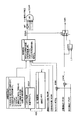
図2は、本発明の一実施形態のシステム構成を示す。
【0026】
アクセル開度センサ1は、ドライバによって踏み込まれたアクセルペダルの操作量(アクセル開度)を検出する。
クランク角センサ2は、単位クランク角毎のポジション信号及び気筒行程位相差毎の基準信号を発生し、前記ポジション信号の単位時間当りの発生数を計測することにより、あるいは前記基準信号発生周期を計測することにより、エンジン回転速度を検出できる。
【0027】
エアフローメータ3は、エンジン4への(単位時間当りの)吸入空気量を検出する。
水温センサ5は、エンジンの冷却水温度を検出する。
【0028】
空燃比センサ6は、排気中の酸素成分等からエンジンに供給される混合気の空燃比を検出する。
エンジン4には、燃料噴射信号によって駆動し、燃料を直接燃焼室内に噴射供給する燃料噴射弁7、燃焼室に装着されて点火を行う点火栓8が設けられる。該燃焼室内への直接噴射方式により、成層燃焼によるリーン化が可能となり、空燃比(当量比)を広範囲に可変制御することができるが、水温や負荷条件その他に応じて均質燃焼に切り換えて運転される。
【0029】
また、エンジン4の吸気通路9には、スロットル弁10が介装され、該スロットル弁10の開度をDCモータ等により電子制御するスロットル制御装置11が備えられている。また、前記スロットル弁10の開度を検出するスロットルセンサ21が装着されている。更に、エンジン4の排気通路12にタービン部13Aを介在させ、吸気通路9にコンプレッサ部13Bを介在させた可変容量型の排気ターボ過給機13が搭載されている。該過給機13は、タービン部13Aのタービン入口面積を可変に絞る可動ベーンを備えており、該可動ベーンの絞り量をアクチュエータによって制御することにより、過給圧を増減制御できるようになっている。
【0030】
また、前記過給機13下流(スロットル弁10より上流)の過給圧を検出する過給圧検出手段としての過給圧センサ14が設けられる。
前記各種センサ類からの検出信号は、コントロールユニット15へ入力され、該コントロールユニット15は、前記センサ類からの信号に基づいて検出される運転状態に応じて前記スロットル制御装置11を介してスロットル弁10の開度を制御し、前記燃料噴射弁7を駆動して燃料噴射量(燃料供給量)を制御し、点火時期を設定して該点火時期で前記点火栓8を点火させる制御を行い、また、前記過給機13の過給圧を制御する。
【0031】
このような構成を有する過給機付エンジンのスロットル弁上流の圧力(過給圧)状態に応じたスロットル弁の開度制御を、図3に示したブロック図を参照して説明する。
【0032】
まず、目標吸入空気量を以下のように算出する。
前記アクセル開度センサ1により検出されたアクセル開度APOに対応するスロットル弁の開口面積AAPOをマップからの検索等により算出する一方、アイドル回転速度制御(ISC)により算出した空気量QSISCとスロットル弁全閉時の漏れ空気量mQLEAKとを加算した値に空気量/スロットル開口面積換算係数mLPMTQAAXを乗じてISCに対応するスロットル開口面積AQSISCを算出し、前記AAPOとAQSISCとを加算して目標スロットル開口面積TTAAPOを算出する(次式参照)。
【0033】
【0034】
TGADNV=TTAAPO/NE/mVOL
TGADNV→TGH0ST
該目標基本体積流量比TQH0STは、スロットル弁全開時の吸入空気量に対する吸入空気量の比率として求められ、TGADNVが大きいときほど大きくなって1に近づく特性を有している。
【0035】
前記目標基本体積流量比TQH0STにスロットル弁全開時の基準当量比(理論空燃比相当値=1)相当の目標基本吸入空気量TTPSTを算出する。即ち、均質ストイキ燃焼(理論空燃比での均質燃焼)でのエンジン回転速度NEと目標トルクとに応じた過給圧PCHSを発生している状態でのスロットル弁全開時のシリンダ吸入空気量を、過給無しの標準大気圧Pa(=760[mmHg])状態でのスロットル弁全開時のシリンダ吸入空気量TP100に、前記ストイキ時の平衡過給圧PCHSと大気圧Paとの比(PCHS/Pa)を乗算することによって算出し、該算出したシリンダ吸入空気量を、前記目標基本体積流量比TQH0STに乗算することによって目標基本吸入空気量TTPSTを算出する(次式参照)。
【0036】
TTPST=TQH0ST×TP100×PCHS/Pa
また、エンジン運転状態に基づいて目標当量比TFBYA00を可変に制御するので、前記基準当量比に対応した目標基本吸入空気量TTPSTを目標当量比TFBYA00で除算し、さらに、当量比によって変化する燃焼効率に基づいて設定された燃焼効率補正係数ITAFを乗じることにより、目標当量比相当の目標吸入空気量TTPを算出する(次式参照)。ここで、前記燃焼効率ITAFは、当量比が小さいリーン燃焼時ほど燃焼効率が高く、燃料量が少なくて済むので、これに伴い空気量も減少させるように小さい値(<1)となるように設定される。
【0037】
TTP=TTPST/TFBYA00×ITAF
このようにして設定された目標吸入空気量TTPに対し、アクセル開度を変化させた過渡時の過給圧変化の遅れを抑制して、所望の過給圧過渡特性が得られるように補正するための過渡補正係数ITAPD0を以下のようにして算出する。
【0038】
以下に、前記過渡補正係数ITAPD0算出の詳細を、図4に示したブロック図に基づいて説明する。
まず、平衡過給圧PCHに、時系列の加重平均演算を行って所望の加減速立ち上がり性能を得るための遅れ処理を施して目標過給圧PCTRGとする(次式参照) 。
【0039】
PCTRG=PCH×τPC1+PCTRG(old)×(1−τPC1)
ここで、平衡過給圧PCHは、同一運転状態に維持されたときに平衡する過給圧であり、エンジン負荷に相当する前記目標基本体積流量比TQH0STとエンジン回転速度NEとに基づいてマップからの検索等により求めるが、均質ストイキ燃焼時(PCHS)、成層リーン燃焼時(PCHLH)、均質リーン燃焼時(PCHLS)とで別個に算出する。また、重み係数τPCも目標基本体積流量比TQH0STとに基づいてマップからの検索等により求める。そして、フラグFTFMCHの値に基づいてこれら燃焼状態に応じた各遅れ処理値を選択する。
【0040】
一方、前記目標過給圧PCTRGの変化に伴う実際の過給圧の変化を推定し、推定過給圧PCESTを演算する。該推定過給圧PCESTも各燃焼毎の平衡過給圧PCHに、次式のように遅れ処理を施して算出するが、目標過給圧PCTRGに比較して遅れを持たせるように重み係数τPC2を前記τPC1より十分小さい値に設定している。この機能が、本発明の過給圧推定手段を構成する。
【0041】
PCEST=PCH×τPC2+PCEST(old)×(1−τPC2)
そして、前記目標過給圧PCTRGを前記推定過給圧PCESTで除算することにより、前記目標吸入空気量TTP0の過渡補正係数ITAPD0を算出する。
【0042】
次に、上記のようにして演算された推定過給圧PCESTと、実際に検出された過給圧とを比較して異常の有無を診断し、異常発生時には、フェイルセーフ処理を行う。
【0043】
具体的な診断と、フェイルセーフ処理を、図5のブロック図を参照しつつ図6のフローチャートに従って説明する。当該フローは所定の周期で実行される。
ステップ(図ではSと記す。以下同様)1〜ステップ4では、診断許可条件を判定する。
【0044】
まず、ステップ1では、本エンジンが当該診断を必要とするエンジンであるか否かをフラグFETDの値で判定し、フラグFETDの値が1のときは、診断が不要と判断して診断を行うことなく、ステップ10へ進む。即ち、エンジンによっては、該診断を必要としない機種もあるが、プログラムを共通化してソフトウエアによるスイッチング判定を行うことにより共通のCPUを用いることができ、コスト低減を図れる。
【0045】
ステップ1で、フラグFETDの値が0と判定されたときは、ステップ2へ進み、異常診断フラグTETDFSの値を判定する。そして、フラグTETDFSの値が1のときは、すでに異常ありとの診断がなされているときであり、この場合は、再度の診断を行うことなく後述するフェールセーフ処理を継続して行うので、ステップ10へ進む。これにより、診断の演算負荷を軽減できる。
【0046】
ステップ2で異常診断フラグTETDFSの値が0と判定されたときは、ステップ3へ進み、前記過給圧センサ14の故障の有無をフラグVPBNGの値に基づいて判定する。そして、フラグVPBNGの値が1のときは、過給圧センサ14が故障している場合であり、この場合は、該過給圧センサ14の検出値との比較で行われる当該診断の信頼性を確保できないため、該診断を行うことなくステップ10へ進む。なお、過給圧センサ14の出力値(電圧)が正常範囲にあるか否かで故障の有無が診断される。
【0047】
ステップ3でフラグVPBNGの値が0と判定されたときは、ステップ4へ進み、前記スロットルセンサ21により検出されるスロットル弁10の開度TTPOPSが、所定開度以上で全開に近い高負荷状態であるか否かを判定する。そして該所定開度以上と判定されたときは、診断を行うことなくステップ10へ進む。即ち、全開に近い高負荷状態で更にアクセルを踏み込んで加速操作を行ったような場合は、過給圧センサ14で検出される実際の過給圧は十分大きい値を示し、後述する遅れ処理演算で算出される推定過給圧との差が大きいため、異常有りとの誤診断を下してしまう可能性があるので、このような場合は診断を禁止する。
【0048】
以上ステップ1〜ステップ4の診断許可条件の判定を行うことにより、高い診断信頼性を確保できる。
そして、前記ステップ4でスロットル弁10の開度が、所定開度未満のときは、前記各診断許可条件が全て満たされたので、ステップ5以降へ進んで診断を行う。
【0049】
まず、ステップ5では、過給圧センサ14からの検出信号Pcをノイズ処理(加重平均等のなまし処理)して実過給圧PBTEAVを検出する。
ステップ6では、前記推定過給圧PCESTに判定しきい値係数NGTEUA(>1、例えば1.28) を乗じて、判定しきい値DPBNGを算出する。
【0050】
ステップ7では、前記実過給圧PBTEAVが前記判定しきい値DPBNG以上であるか否かを判定する。
ステップ7で、PBTEAV≧DPBNGと判定されたときは、ステップ8へ進んで、該状態が所定時間TMTENG(例えば10ms)以上継続したか否かを判定する。
【0051】
そして、所定時間TMTENG以上継続したと判定された場合は、ステップ9へ進んで異常あり(過給機系統の故障又は過給圧推定演算のNG)との診断を下し、異常診断フラグTETDFSを1にセットする。これにより、異常の警告が発せられる。
【0052】
また、上記以外の場合(ステップ7又はステップ8の判定がNOの場合)は、異常診断フラグTETDFSは前回値に保持される。即ち、一度異常ありとの診断を下した後は、少なくとも現在の運転を終了するまでは該診断結果が保持される。以上示したステップ1〜ステップ9の診断機能が本発明の診断手段を構成する。
【0053】
次いでステップ10では、前記異常診断フラグTETDFSを判別し、0にセットされているとき、つまり異常無しとの診断が下されているときには、ステップ11へ進んで、前記目標過給圧PCTRGを推定過給圧PCESTで除算して算出された過渡補正係数ITAPD0を、そのままITAPDとしてセットした後、このルーチンを終了する。即ち、過給機系統や過給圧推定演算が正常である場合は、前記過渡補正係数ITAPD0を用いて目標吸入空気量TTP0を補正することにより、過給圧の遅れを適度に小さくして所望の過給圧過渡特性が得られるようにする。
【0054】
また、ステップ10で前記異常診断フラグTETDFSが1にセットされていると判別されたとき、つまり異常ありとの診断が下されているときには、ステップ12へ進んで、前記過渡補正係数ITAPD0と、「1」とを比較し、両者のうち小さいほうを選択して、ITAPDとしてセットする。
【0055】
次いで、ステップ13へ進んでリーン燃焼フラグFLEANPの値を0にリセットすることにより、リーン燃焼(均質リーン燃焼及び成層燃焼) を禁止して均質ストイキ燃焼を行わせるようにする。
【0056】
即ち、過給機系統の故障や過給圧推定演算のNGを生じたりしている状態では、前記過渡補正係数ITAPD0の値に信頼性が無く、実際の過給圧に対して推定過給圧PCESTを低い値で推定しているので、過渡補正係数ITAPD0は、実際に補正すべき値より過大な値として算出されることになる。その結果、加速操作時に過大な値に算出された過渡補正係数ITAPD0を用いて吸入空気量を増大補正すると、過給圧が過度に上昇して予測しない急激な加速を生じることとなる。そこで、過渡補正係数ITAPDを1以下の値に制限することにより、過給圧が増大する方向の補正を禁止して、前記予測しない急激な加速の発生を防止する。
【0057】
また、減速時などに過給圧の減少が遅く実際の過給圧が推定過給圧PCESTより大きくなりすぎる結果として、異常ありとの診断が下されるようなこともありうるが、その場合に1より小さい値に算出された過渡補正係数ITAPD0を用いて吸入空気量を減少補正し、減速を速める方向の補正を行うことは、妥当な補正である。したがって、過給圧を減少させる方向の補正は、これを許容するように「1」との比較で小さいほうが選択されるようにする。
【0058】
また、異常ありとの診断時には強制的に均質ストイキ燃焼に切り換えることにより、燃焼の安定性を確保することができる。この他、一般的に、前記目標過給圧や吸入空気量補正を含めたリーン燃焼時の過給圧の過渡特性を、ドライバに馴染みのある均質ストイキ燃焼時の加速フィーリング(アクセル開度に対する加速特性)に近づけるように、設定している場合が多いので、前記吸入空気量補正を禁止した場合には、該過渡特性が得られなくなるので、均質ストイキ燃焼に切り換えることにより、可及的に良好な加速フィーリングを確保できるという効果もある。
【0059】
以上示したステップ10〜ステップ13の機能が本発明のフェールセーフ手段を構成する。
図3に戻って上記過渡補正係数ITAPDを前記目標吸入空気量TTPに乗じて仮想目標吸入空気量TTPDを算出する。
【0060】
TTPD=TTP×ITPAD
この仮想目標吸入空気量TTPDを目標値としてスロットル弁開度を制御する。
即ち、前記仮想目標吸入空気量TTPDを、大気圧相当でのスロットル弁全開時のシリンダ吸入空気量TP100に、平衡過給圧PCHと標準大気圧Paとの比PCH/Paを乗じた値つまり該平衡過給圧PCHでのスロットル弁全開時のシリンダ吸入空気量で除算することにより、該平衡過給圧PCH状態での体積流量比TGQH0を算出し、該体積流量比TGQH0に基づいてマップからの検索等により、体積効率相当値TDADNVを算出する。この値TDADNVにエンジン回転速度NE,排気量mVOLを順次乗じて、目標スロットル弁開口面積TAAIRを算出し、該目標スロットル弁開口面積TAAIRを目標スロットル弁開度TDTVOに変換し、該目標スロットル弁開度TDTVOとなるようにスロットル弁の開度を制御する(次式参照)。
【0061】
TGQH0=TTPD×TP100×PCH/Pa
TGQH0→TDADNV
TAAIR=TDADNV×NE×mVOL
TAAIR→TDTVO
このようにすれば、過給機系統の故障や過給圧推定演算のNGがない正常時には、
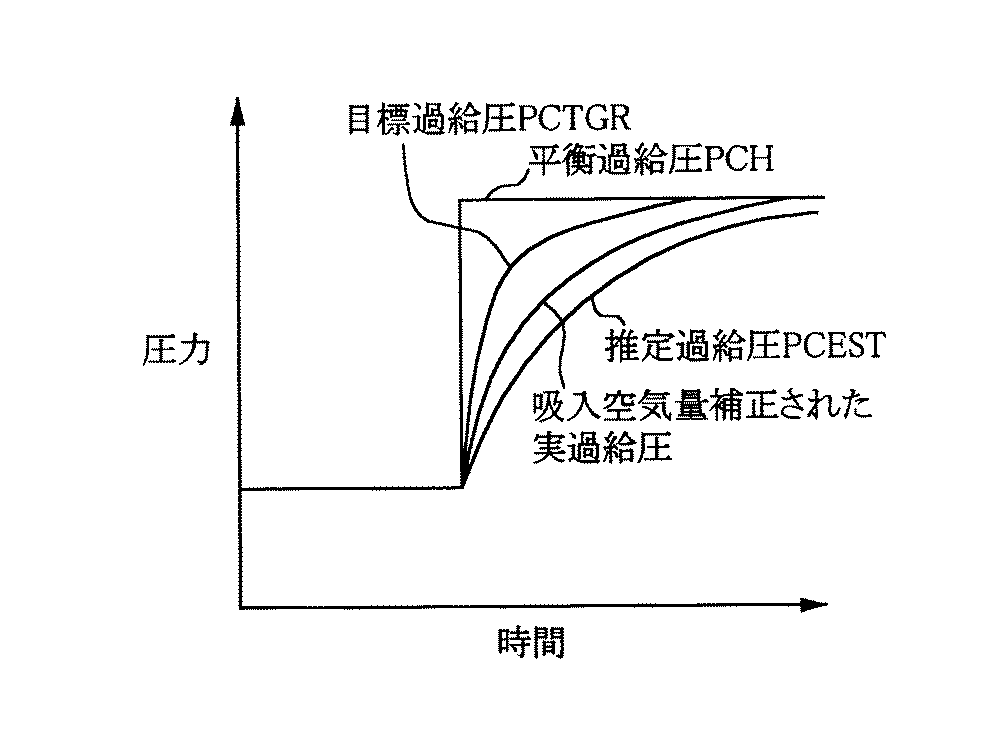
前記目標過給圧PCTRGを推定過給圧PCESTで除算した過渡補正係数ITAPD0を用いて目標吸入空気量TTP0を補正した仮想目標吸入空気量TTPが得られるようにスロットル弁開度が制御されることにより、過給圧の遅れを適度に抑制した所望の過給圧過渡特性が得られる(図7参照)。したがって、加減速時に要求に応じたトルク応答が得られ、また、均質燃焼と成層燃焼との切り換え時のトルク変化を抑制できる。このように、推定過給圧PCESTに基づいて得られる過渡補正係数ITAPD0を用いて過給圧過渡特性を補正制御する機能が、本発明のエンジン制御手段を構成する。
【0062】
また、過給機系統の故障や過給圧推定演算のNGがあると診断されたときには、目標吸入空気量TTP0を増大する方向の補正が禁止されることにより、予測しない急激な加速の発生を防止でき、良好な運転性を確保できる。
【図面の簡単な説明】
【図1】本発明の構成・機能を示すブロック図。
【図2】本発明の実施形態のシステム構成を示す図。
【図3】同上実施形態の機能構成を示すブロック図。
【図4】同上実施形態の過渡補正係数演算部分の機能構成を示すブロック図。
【図5】同上実施形態の過給圧異常診断及びフェールセーフ処理の機能構成を示すブロック図。
【図6】同上実施形態の過給圧異常診断及びフェールセーフ処理のフローチャート。
【図7】同上実施形態の過給圧系正常時の過給圧過渡特性を示す図。
【符号の説明】
1 アクセル操作量センサ
2 クランク角センサ
4 エンジン
7 燃料噴射弁
9 吸気通路
10 スロットル弁
11 スロットル弁制御装置
12 排気通路
13 可変容量ターボ過給機
14 過給圧センサ
15 コントロールユニット
21 スロットルセンサ[0001]
BACKGROUND OF THE INVENTION
The present invention provides an exhaust turbocharger and a throttle control device that electronically controls the throttle valve opening, and is used in an engine that estimates a boost pressure upstream of the throttle for engine control (hereinafter simply referred to as a boost pressure). TECHNICAL FIELD
[0002]
[Prior art]
Conventionally, as a control device for an intake air amount of an engine provided with a throttle control device for electronically controlling the throttle valve opening, there is a device as disclosed in, for example, Japanese Patent Application Laid-Open No. 62-110536.
[0003]
In this system, the target torque of the engine is calculated based on the accelerator opening and the engine speed, and the target throttle valve opening is calculated based on the target torque and the engine speed to obtain the target intake air amount. The throttle valve is controlled.
[0004]
By the way, when electronic control of the throttle valve is performed with an engine equipped with an exhaust turbocharger, depending on the operating conditions such as the accelerator opening and the engine speed, during a transient time when the supercharging pressure is changed according to changes in the operating conditions. By controlling the throttle valve opening so that the determined supercharging pressure at equilibrium is reached at a desired speed, it is possible to improve the driving performance such as improving the acceleration feeling.
[0005]
In addition, in an engine that switches between stratified combustion and homogeneous combustion according to the operating conditions, the supercharging pressure that generates the same torque for each combustion differs, so the supercharging pressure has good responsiveness when switching combustion. In order to make the transient characteristics during stratified combustion similar to those during homogeneous combustion, the throttle valve opening control is performed so that the intake air amount during transients is corrected to correct the boost pressure transient characteristics. Has been attempted to do.
[0006]
[Problems to be solved by the invention]
In order to execute the throttle valve opening control described above, the supercharging pressure that changes during the transition is estimated, and the target supercharging pressure that is set based on the engine operating state such as the accelerator opening and the engine speed is estimated. Comparing with the supply pressure, correcting the target intake air amount according to the magnitude or ratio of the deviation between them, and controlling the throttle valve opening so as to obtain the corrected target intake air amount, Attempts have been made to perform control so as to obtain a supercharging pressure transient characteristic (characteristic that reaches an equilibrium supercharging pressure at a desired speed). In addition, for another engine control, it is common to provide a sensor for detecting an actual boost pressure. For example, in the case of the control, an actual detected boost pressure is used instead of an estimated boost pressure. Even if the control is performed based on the deviation from the target boost pressure, the transient characteristic of the boost pressure determined by the actual boost pressure is not necessarily the desired characteristic, and the desired boost pressure can be obtained by using the estimated value. Transient characteristics can be obtained.
[0007]
However, when the engine control is performed using the estimated value of the supercharging pressure as described above, if an abnormality of the supercharging system or NG of the supercharging pressure estimation calculation occurs, the engine control can be performed normally. It may not be possible and engine performance may be degraded. Specifically, a problem arises in that a more rapid acceleration (UA) than predicted by the accelerator depression amount occurs during acceleration.
[0008]
The present invention has been made paying attention to such a conventional problem. In the engine control using the estimated value of the supercharging pressure, the presence or absence of abnormality is diagnosed, and an appropriate failure is detected when the abnormality occurs. An object of the present invention is to provide a control device for a supercharged engine in which safe control is performed.
[0009]
[Means for Solving the Problems]
For this reason, as shown in FIG.
In a turbocharged engine comprising a throttle control device that electronically controls the throttle valve opening to a target value, and an exhaust turbocharger upstream of the throttle valve,
Supercharging pressure estimating means for estimating the supercharging pressure upstream of the throttle valve based on the engine operating state;
By setting a target boost pressure upstream of the throttle valve and correcting the target intake air amount based on the difference between the target boost pressure and the estimated value of the boost pressure estimated by the boost pressure estimating means, Engine control means for correcting and controlling the transient characteristics of the supercharging pressure via the throttle valve opening control by the throttle control device ;
A supercharging pressure detecting means for detecting an actual supercharging pressure upstream of the throttle valve;
A diagnostic means for diagnosing the presence or absence of an abnormality by comparing the supercharging pressure estimated by the supercharging pressure estimating means with the supercharging pressure detected by the supercharging pressure detecting means;
A fail-safe means for prohibiting correction of a target intake air amount based on an estimated value of a boost pressure in the engine control means when a diagnosis is made that there is an abnormality by the diagnosis means;
It is characterized by including.
[0010]
According to the invention of
While performing engine control based on the supercharging pressure estimated by the supercharging pressure estimation means, the supercharging pressure detection means detects the actual supercharging pressure upstream of the throttle valve, and detects the estimated supercharging pressure. By comparing with the supercharging pressure, the presence or absence of abnormality such as failure of the supercharger system or NG of the supercharging pressure estimation calculation is diagnosed.
[0011]
Therefore, when an abnormality occurs, it is possible to deal with engine control based on the estimated supercharging pressure.
In addition, the engine control means moderates the delay of the boost pressure by correcting the intake air amount via the throttle valve opening control based on the difference between the target boost pressure and the estimated value of the boost pressure. Control to obtain the desired supercharging pressure transient characteristics that are suppressed to a low level, thereby obtaining a torque response as required during acceleration / deceleration, and a torque change when switching between homogeneous combustion and stratified combustion. Can be suppressed.
In addition, when the diagnosis that there is an abnormality is made and the turbocharger system has failed or the NG of the boost pressure estimation calculation has occurred, the estimated value of the boost pressure is not reliable. If the correction of the intake air amount based on this is performed, there is a possibility that the supercharging pressure will rise rapidly and sudden acceleration will occur unexpectedly. Therefore, in such a case, the fail-safe means prohibits the correction of the target intake air amount based on the estimated value of the supercharging pressure, thereby preventing the unexpected sudden acceleration.
The invention according to
The diagnosis means makes a diagnosis that there is an abnormality under a condition including a case where a deviation between the estimated value and the detected value of the supercharging pressure is larger than a predetermined value or a predetermined ratio.
[0012]
According to the invention of
When the deviation between the estimated value of the boost pressure and the detected value is larger than the predetermined value or a predetermined ratio, it is highly possible that the estimated value is greatly deviated from the actual boost pressure due to some abnormality. High diagnostic accuracy can be ensured by lowering.
[0017]
The invention according to
When the diagnosis means diagnoses that there is an abnormality, the correction of the target intake air amount is prohibited and the control to make the air-fuel ratio lean is prohibited.
[0018]
According to the invention of
Further, when a diagnosis that there is an abnormality is made, the stability of combustion can be ensured by prohibiting lean combustion and switching to homogeneous stoichiometric combustion or the like. Further, for example, it is possible to approach the acceleration feeling (acceleration characteristics with respect to the accelerator opening) at the time of homogeneous stoichiometric combustion familiar to the driver.
[0019]
The invention according to
The prohibition of the correction of the target supercharging pressure is prohibited only in the direction of increasing the target supercharging pressure.
[0020]
According to the invention of
When the vehicle is decelerating, the supercharging pressure decreases slowly and the actual supercharging pressure becomes larger than the estimated supercharging pressure. As a result, it may be diagnosed that there is an abnormality. It is a reasonable correction to correct the supply pressure so that the deceleration is accelerated. Accordingly, only the correction in the direction in which the target boost pressure is increased is prohibited, and the correction in the direction in which the boost pressure is decreased is allowed, thereby ensuring good deceleration performance.
[0021]
The invention according to
The diagnosis means prohibits diagnosis when the supercharging pressure detection means is diagnosed as abnormal.
[0022]
According to the invention of
When the supercharging pressure detection means is diagnosed as abnormal, the reliability of the diagnosis performed by comparing with the detected value of the supercharging pressure cannot be ensured, so the diagnosis is prohibited by securing the reliability of the diagnosis it can.
[0023]
The invention according to claim 6
The diagnosis means prohibits diagnosis at a high load close to full open.
[0024]
According to the invention of claim 6 ,
When acceleration is performed by further depressing the accelerator in a high load state that is almost fully open, the actual boost pressure detection value shows a sufficiently large value, and the difference from the estimated boost pressure becomes large. In such a case, the reliability of the diagnosis can be ensured by prohibiting the diagnosis.
[0025]
DETAILED DESCRIPTION OF THE INVENTION
Hereinafter, embodiments of the present invention will be described with reference to the drawings.
FIG. 2 shows a system configuration of an embodiment of the present invention.
[0026]
The
The
[0027]
The
The
[0028]
The air-fuel ratio sensor 6 detects the air-fuel ratio of the air-fuel mixture supplied to the engine from the oxygen component or the like in the exhaust gas.
The
[0029]
Further, a
[0030]
Further, a supercharging
Detection signals from the various sensors are input to the
[0031]
The opening control of the throttle valve according to the pressure (supercharging pressure) state upstream of the throttle valve of the turbocharged engine having such a configuration will be described with reference to the block diagram shown in FIG.
[0032]
First, the target intake air amount is calculated as follows.
The throttle valve opening area AAPO corresponding to the accelerator opening APO detected by the
[0033]
[0034]
TGADNV = TTAAPO / NE / mVOL
TGADNV → TGH0ST
The target basic volume flow rate ratio TQH0ST is obtained as a ratio of the intake air amount to the intake air amount when the throttle valve is fully opened, and has a characteristic that it increases as TGADNV increases and approaches 1.
[0035]
A target basic intake air amount TTPST corresponding to a reference equivalent ratio (theoretical air-fuel ratio equivalent value = 1) when the throttle valve is fully opened is calculated as the target basic volume flow ratio TQH0ST. That is, the cylinder intake air amount when the throttle valve is fully opened in the state where the supercharging pressure PCHS is generated according to the engine speed NE and the target torque in homogeneous stoichiometric combustion (homogeneous combustion at the stoichiometric air-fuel ratio) The ratio (PCHS / Pa) of the equilibrium supercharging pressure PCHS and the atmospheric pressure Pa at the time of stoichiometry is added to the cylinder intake air amount TP100 when the throttle valve is fully opened in the standard atmospheric pressure Pa (= 760 [mmHg]) state without supercharging. ), And the target basic intake air amount TTPST is calculated by multiplying the calculated cylinder intake air amount by the target basic volume flow rate ratio TQH0ST (see the following equation).
[0036]
TTPST = TQH0ST × TP100 × PCHS / Pa
Further, since the target equivalent ratio TFBYA00 is variably controlled based on the engine operating state, the target basic intake air amount TTPST corresponding to the reference equivalent ratio is divided by the target equivalent ratio TFBYA00, and further, the combustion efficiency that changes depending on the equivalent ratio The target intake air amount TTP corresponding to the target equivalent ratio is calculated by multiplying the combustion efficiency correction coefficient ITAF set based on (see the following equation). Here, the combustion efficiency ITAF has a smaller value (<1) so that the leaner combustion with a lower equivalence ratio results in higher combustion efficiency and less fuel, and accordingly, the air amount is also reduced. Is set.
[0037]
TTP = TTPST / TFBYA00 × ITAF
The target intake air amount TTP set in this way is corrected so as to obtain a desired boost pressure transient characteristic by suppressing a delay in the boost pressure change at the time when the accelerator opening is changed. The transient correction coefficient ITAPD0 is calculated as follows.
[0038]
Details of the calculation of the transient correction coefficient ITAPD0 will be described below based on the block diagram shown in FIG.
First, a delay process for obtaining a desired acceleration / deceleration rising performance by performing a time-series weighted average calculation is performed on the equilibrium boost pressure PCH to obtain a target boost pressure PCTRG (see the following formula).
[0039]
PCTRG = PCH × τPC1 + PCTRG (old) × (1−τPC1)
Here, the equilibrium supercharging pressure PCH is a supercharging pressure that is balanced when maintained in the same operation state, and is calculated from a map based on the target basic volume flow ratio TQH0ST corresponding to the engine load and the engine speed NE. However, it is calculated separately for homogeneous stoichiometric combustion (PCHS), stratified lean combustion (PCHLH), and homogeneous lean combustion (PCHLS). Further, the weighting coefficient τPC is also obtained by searching from the map based on the target basic volume flow rate ratio TQH0ST. Then, each delay processing value corresponding to the combustion state is selected based on the value of the flag FTFMCH.
[0040]
On the other hand, the change in the actual supercharging pressure accompanying the change in the target supercharging pressure PCTRG is estimated, and the estimated supercharging pressure PCEST is calculated. The estimated supercharging pressure PCEST is also calculated by applying a delay process to the equilibrium supercharging pressure PCH for each combustion as shown in the following equation, but with a weight coefficient τPC2 so as to give a delay compared to the target supercharging pressure PCTRG. Is set to a value sufficiently smaller than τPC1. This function constitutes the supercharging pressure estimation means of the present invention.
[0041]
PCEST = PCH × τPC2 + PCEST (old) × (1−τPC2)
Then, the transient correction coefficient ITAPD0 for the target intake air amount TTP0 is calculated by dividing the target boost pressure PCTRG by the estimated boost pressure PCEST.
[0042]
Next, the estimated boost pressure PCEST calculated as described above is compared with the actually detected boost pressure to diagnose the presence or absence of an abnormality, and when an abnormality occurs, a fail-safe process is performed.
[0043]
Specific diagnosis and fail-safe processing will be described according to the flowchart of FIG. 6 with reference to the block diagram of FIG. The flow is executed at a predetermined cycle.
In step (denoted as S in the figure, the same applies hereinafter) 1 to step 4, diagnosis permission conditions are determined.
[0044]
First, in
[0045]
If it is determined in
[0046]
If it is determined in
[0047]
When it is determined in
[0048]
By performing the determination of the diagnosis permission conditions in
When the opening degree of the
[0049]
First, at
In step 6, the estimated threshold pressure DPBNG is calculated by multiplying the estimated boost pressure PCEST by a determination threshold coefficient NGTEUA (> 1, for example, 1.28).
[0050]
In
When it is determined in
[0051]
If it is determined that the predetermined time TMTENG or more has been continued, the routine proceeds to step 9 where a diagnosis of abnormality (supercharger system failure or supercharging pressure estimation calculation NG) is made, and the abnormality diagnosis flag TETDFS is set. Set to 1. As a result, an abnormality warning is issued.
[0052]
In cases other than the above (when the determination in
[0053]
Next, at
[0054]
When it is determined in
[0055]
Next, the routine proceeds to step 13, where the value of the lean combustion flag FLEANP is reset to 0, thereby prohibiting lean combustion (homogeneous lean combustion and stratified combustion) and performing homogeneous stoichiometric combustion.
[0056]
In other words, in a state where a turbocharger system failure or supercharging pressure estimation calculation NG occurs, the value of the transient correction coefficient ITAPD0 is not reliable, and the estimated supercharging pressure relative to the actual supercharging pressure. Since PCEST is estimated at a low value, the transient correction coefficient ITAPD0 is calculated as a value that is larger than the value to be actually corrected. As a result, if the intake air amount is increased and corrected using the transient correction coefficient ITAPD0 calculated to an excessive value during the acceleration operation, the supercharging pressure rises excessively and unpredictable rapid acceleration occurs. Therefore, by limiting the transient correction coefficient ITAPD to a value of 1 or less, correction in the direction in which the supercharging pressure increases is prohibited, thereby preventing the unexpected sudden acceleration.
[0057]
In addition, there is a possibility that a diagnosis of an abnormality is made as a result of the decrease in the supercharging pressure being slow and the actual supercharging pressure becoming too much larger than the estimated supercharging pressure PCEST. It is a reasonable correction to reduce the intake air amount using the transient correction coefficient ITAPD0 calculated to a value smaller than 1 and to correct the direction in which the deceleration is accelerated. Accordingly, the correction in the direction of decreasing the supercharging pressure is selected to be smaller in comparison with “1” so as to allow this.
[0058]
In addition, when it is diagnosed that there is an abnormality, the combustion stability can be ensured by forcibly switching to homogeneous stoichiometric combustion. In addition, generally, the transient characteristics of the supercharging pressure during lean combustion including the target supercharging pressure and intake air amount correction are expressed in terms of acceleration feeling during homogeneous stoichiometric combustion (according to the accelerator opening). In many cases, it is set so as to be close to the acceleration characteristic). Therefore, when the intake air amount correction is prohibited, the transient characteristic cannot be obtained. Therefore, by switching to homogeneous stoichiometric combustion, There is also an effect that a good acceleration feeling can be secured.
[0059]
The functions of
Returning to FIG. 3, the virtual target intake air amount TTPD is calculated by multiplying the transient correction coefficient ITAPD by the target intake air amount TTP.
[0060]
TTPD = TTP × ITPAD
The throttle valve opening is controlled using the virtual target intake air amount TTPD as a target value.
That is, the virtual target intake air amount TTPD is a value obtained by multiplying the cylinder intake air amount TP100 when the throttle valve is fully opened corresponding to the atmospheric pressure by the ratio PCH / Pa between the equilibrium boost pressure PCH and the standard atmospheric pressure Pa. by dividing the cylinder intake air amount of the throttle valve fully opened in the equilibrium boost pressure PCH, to calculate the volumetric flow ratio TGQH0 in the equilibrium boost pressure PCH state, from the map based on the said volume flow ratio TGQH0 A volume efficiency equivalent value TDADNV is calculated by searching or the like. The value TDADNV is sequentially multiplied by the engine speed NE and the displacement mVOL to calculate the target throttle valve opening area TAAIR, the target throttle valve opening area TAAIR is converted into the target throttle valve opening TDTVO, and the target throttle valve opening The opening degree of the throttle valve is controlled so that the degree becomes TDTVO (see the following formula).
[0061]
TGQH0 = TTPD × TP100 × PCH / Pa
TGQH0 → TDDADNV
TAAIR = TDADNV x NE x mVOL
TAAIR → TDTVO
In this way, when there is no failure of the turbocharger system and there is no NG of the supercharging pressure estimation calculation,
The throttle valve opening is controlled so as to obtain a virtual target intake air amount TTP obtained by correcting the target intake air amount TTP0 by using a transient correction coefficient ITAPD0 obtained by dividing the target boost pressure PCTRG by the estimated boost pressure PCEST. Thus, a desired boost pressure transient characteristic in which the delay of the boost pressure is moderately suppressed can be obtained (see FIG. 7). Therefore, a torque response according to the request can be obtained during acceleration / deceleration, and torque change at the time of switching between homogeneous combustion and stratified combustion can be suppressed. As described above, the function of correcting and controlling the boost pressure transient characteristic using the transient correction coefficient ITAPD0 obtained based on the estimated boost pressure PCEST constitutes the engine control means of the present invention.
[0062]
In addition, when it is diagnosed that there is a turbocharger system failure or a supercharging pressure estimation calculation NG, correction in the direction of increasing the target intake air amount TTP0 is prohibited, thereby causing an unexpected sudden acceleration. Can be prevented, and good drivability can be secured.
[Brief description of the drawings]
FIG. 1 is a block diagram showing a configuration / function of the present invention.
FIG. 2 is a diagram showing a system configuration according to the embodiment of the present invention.
FIG. 3 is a block diagram showing a functional configuration of the embodiment.
FIG. 4 is a block diagram showing a functional configuration of a transient correction coefficient calculation part according to the embodiment.
FIG. 5 is a block diagram showing a functional configuration of supercharging pressure abnormality diagnosis and fail-safe processing according to the embodiment;
FIG. 6 is a flowchart of boost pressure abnormality diagnosis and fail-safe processing according to the embodiment;
FIG. 7 is a graph showing a boost pressure transient characteristic when the boost pressure system is normal according to the embodiment;
[Explanation of symbols]
DESCRIPTION OF
Claims (6)
スロットル弁上流の過給圧をエンジン運転状態に基づいて推定する過給圧推定手段と、
スロットル弁上流の目標過給圧を設定し、該目標過給圧と前記過給圧推定手段により推定された過給圧の推定値との相違に基づいて目標吸入空気量を補正することにより、前記スロットル制御装置によるスロットル弁開度制御を介して、過給圧の過渡特性を補正制御するエンジン制御手段と、
前記スロットル弁上流の実際の過給圧を検出する過給圧検出手段と、
前記過給圧推定手段により推定された過給圧と、前記過給圧検出手段により検出された過給圧とを比較して、異常の有無を診断する診断手段と、
前記診断手段によって異常ありとの診断が下されたときは、前記エンジン制御手段における過給圧の推定値に基づく目標吸入空気量の補正を禁止するフェールセーフ手段と、
を含んで構成したことを特徴とする過給機付エンジンの制御装置。In a turbocharged engine comprising a throttle control device that electronically controls the throttle valve opening to a target value, and an exhaust turbocharger upstream of the throttle valve,
Supercharging pressure estimating means for estimating the supercharging pressure upstream of the throttle valve based on the engine operating state;
By setting a target boost pressure upstream of the throttle valve and correcting the target intake air amount based on the difference between the target boost pressure and the estimated value of the boost pressure estimated by the boost pressure estimating means, Engine control means for correcting and controlling the transient characteristics of the supercharging pressure via the throttle valve opening control by the throttle control device ;
A supercharging pressure detecting means for detecting an actual supercharging pressure upstream of the throttle valve;
A diagnostic means for diagnosing the presence or absence of an abnormality by comparing the supercharging pressure estimated by the supercharging pressure estimating means with the supercharging pressure detected by the supercharging pressure detecting means;
A fail-safe means for prohibiting correction of a target intake air amount based on an estimated value of a boost pressure in the engine control means when a diagnosis is made that there is an abnormality by the diagnosis means;
A control device for a supercharged engine, comprising:
Priority Applications (1)
| Application Number | Priority Date | Filing Date | Title |
|---|---|---|---|
| JP26580399A JP3905261B2 (en) | 1999-09-20 | 1999-09-20 | Control device for turbocharged engine |
Applications Claiming Priority (1)
| Application Number | Priority Date | Filing Date | Title |
|---|---|---|---|
| JP26580399A JP3905261B2 (en) | 1999-09-20 | 1999-09-20 | Control device for turbocharged engine |
Publications (2)
| Publication Number | Publication Date |
|---|---|
| JP2001090543A JP2001090543A (en) | 2001-04-03 |
| JP3905261B2 true JP3905261B2 (en) | 2007-04-18 |
Family
ID=17422272
Family Applications (1)
| Application Number | Title | Priority Date | Filing Date |
|---|---|---|---|
| JP26580399A Expired - Lifetime JP3905261B2 (en) | 1999-09-20 | 1999-09-20 | Control device for turbocharged engine |
Country Status (1)
| Country | Link |
|---|---|
| JP (1) | JP3905261B2 (en) |
Families Citing this family (14)
| Publication number | Priority date | Publication date | Assignee | Title |
|---|---|---|---|---|
| JP4196343B2 (en) | 2004-01-26 | 2008-12-17 | トヨタ自動車株式会社 | Internal combustion engine and method for operating the same |
| JP2006291816A (en) * | 2005-04-08 | 2006-10-26 | Toyota Motor Corp | Abnormality determination device of turbocharger |
| EP1793106B1 (en) * | 2005-11-30 | 2010-03-03 | Delphi Technologies, Inc. | Method and apparatus for controlling a combustion engine |
| JP4815294B2 (en) * | 2006-07-25 | 2011-11-16 | 本田技研工業株式会社 | Failure detection device for supercharging pressure control means in engine supercharging device |
| JP4827758B2 (en) * | 2007-02-05 | 2011-11-30 | Udトラックス株式会社 | Fault diagnosis device for variable valve timing control device |
| JP5428914B2 (en) * | 2010-02-09 | 2014-02-26 | 三菱自動車工業株式会社 | Vehicle control device |
| US9644553B2 (en) | 2013-03-27 | 2017-05-09 | Toyota Jidosha Kabushiki Kaisha | Control device for internal combustion engine |
| JP6179464B2 (en) * | 2014-05-30 | 2017-08-16 | トヨタ自動車株式会社 | Supercharging pressure estimation device for internal combustion engine |
| JP6486852B2 (en) * | 2016-03-03 | 2019-03-20 | 日立オートモティブシステムズ株式会社 | Control device and control method for internal combustion engine |
| GB2558604B (en) * | 2017-01-09 | 2020-02-26 | Delphi Automotive Systems Lux | Method to detect faults in boost system of a turbocharged engine |
| CN111417772B (en) | 2017-11-29 | 2022-06-24 | 日产自动车株式会社 | Method and device for controlling internal combustion engine for vehicle |
| JP7183973B2 (en) * | 2019-06-24 | 2022-12-06 | トヨタ自動車株式会社 | Engine torque detector |
| JP7159994B2 (en) * | 2019-07-30 | 2022-10-25 | いすゞ自動車株式会社 | Estimation device, estimation method, and vehicle |
| JP7159993B2 (en) * | 2019-07-30 | 2022-10-25 | いすゞ自動車株式会社 | Estimation device, estimation method, and vehicle |
-
1999
- 1999-09-20 JP JP26580399A patent/JP3905261B2/en not_active Expired - Lifetime
Also Published As
| Publication number | Publication date |
|---|---|
| JP2001090543A (en) | 2001-04-03 |
Similar Documents
| Publication | Publication Date | Title |
|---|---|---|
| JP3926522B2 (en) | Intake control device for turbocharged engine | |
| US6779508B2 (en) | Control system of internal combustion engine | |
| JP4583038B2 (en) | Supercharging pressure estimation device for an internal combustion engine with a supercharger | |
| US7509210B2 (en) | Abnormality determination apparatus and method for blow-by gas feedback device, and engine control unit | |
| JP3905261B2 (en) | Control device for turbocharged engine | |
| US9057320B2 (en) | Control device and control method for an internal combustion engine | |
| JP6851323B2 (en) | Wastegate valve control method and control device | |
| JP3136968B2 (en) | An intake pressure abnormality detection device for an internal combustion engine | |
| JP2009221881A (en) | Engine | |
| JP6679554B2 (en) | Control device for internal combustion engine | |
| JP4859731B2 (en) | Control device for internal combustion engine | |
| KR20040057443A (en) | Engine controlling system of diesel vehicle and method thereof | |
| JP3872617B2 (en) | Intake air amount control device for supercharged engine | |
| JP2560695B2 (en) | Deceleration control device for internal combustion engine | |
| JP2006057526A (en) | Failure diagnosis device for internal combustion engine | |
| JP3956458B2 (en) | Fuel injection control device for internal combustion engine | |
| JP4023327B2 (en) | Abnormality diagnosis device for intake system sensor | |
| JP4736485B2 (en) | Control device for internal combustion engine | |
| JP4123340B2 (en) | Engine intake air amount calculation device | |
| JPH10196381A (en) | Control device of internal combustion engine mounted with variable nozzle type turbocharger | |
| JPH0746737Y2 (en) | Control device for engine with supercharger | |
| JP2003148215A (en) | Intake system failure diagnostic device for internal combustion engine and fail safe device | |
| JPS6345444A (en) | Air-fuel ratio controller for internal combustion engine | |
| JP3812111B2 (en) | Control device for internal combustion engine | |
| JP2674126B2 (en) | Internal combustion engine controller with mechanical supercharger |
Legal Events
| Date | Code | Title | Description |
|---|---|---|---|
| A711 | Notification of change in applicant |
Free format text: JAPANESE INTERMEDIATE CODE: A712 Effective date: 20041217 |
|
| A977 | Report on retrieval |
Free format text: JAPANESE INTERMEDIATE CODE: A971007 Effective date: 20050519 |
|
| A131 | Notification of reasons for refusal |
Free format text: JAPANESE INTERMEDIATE CODE: A131 Effective date: 20060829 |
|
| A521 | Written amendment |
Free format text: JAPANESE INTERMEDIATE CODE: A523 Effective date: 20061030 |
|
| TRDD | Decision of grant or rejection written | ||
| A01 | Written decision to grant a patent or to grant a registration (utility model) |
Free format text: JAPANESE INTERMEDIATE CODE: A01 Effective date: 20070109 |
|
| A61 | First payment of annual fees (during grant procedure) |
Free format text: JAPANESE INTERMEDIATE CODE: A61 Effective date: 20070111 |
|
| R150 | Certificate of patent or registration of utility model |
Ref document number: 3905261 Country of ref document: JP Free format text: JAPANESE INTERMEDIATE CODE: R150 Free format text: JAPANESE INTERMEDIATE CODE: R150 |
|
| FPAY | Renewal fee payment (event date is renewal date of database) |
Free format text: PAYMENT UNTIL: 20100119 Year of fee payment: 3 |
|
| FPAY | Renewal fee payment (event date is renewal date of database) |
Free format text: PAYMENT UNTIL: 20110119 Year of fee payment: 4 |
|
| R250 | Receipt of annual fees |
Free format text: JAPANESE INTERMEDIATE CODE: R250 |
|
| FPAY | Renewal fee payment (event date is renewal date of database) |
Free format text: PAYMENT UNTIL: 20120119 Year of fee payment: 5 |
|
| R250 | Receipt of annual fees |
Free format text: JAPANESE INTERMEDIATE CODE: R250 |
|
| FPAY | Renewal fee payment (event date is renewal date of database) |
Free format text: PAYMENT UNTIL: 20130119 Year of fee payment: 6 |
|
| R250 | Receipt of annual fees |
Free format text: JAPANESE INTERMEDIATE CODE: R250 |
|
| FPAY | Renewal fee payment (event date is renewal date of database) |
Free format text: PAYMENT UNTIL: 20140119 Year of fee payment: 7 |
|
| R250 | Receipt of annual fees |
Free format text: JAPANESE INTERMEDIATE CODE: R250 |
|
| EXPY | Cancellation because of completion of term |