JP3904792B2 - Current differential relay - Google Patents
Current differential relay Download PDFInfo
- Publication number
- JP3904792B2 JP3904792B2 JP2000034414A JP2000034414A JP3904792B2 JP 3904792 B2 JP3904792 B2 JP 3904792B2 JP 2000034414 A JP2000034414 A JP 2000034414A JP 2000034414 A JP2000034414 A JP 2000034414A JP 3904792 B2 JP3904792 B2 JP 3904792B2
- Authority
- JP
- Japan
- Prior art keywords
- value
- set value
- terminal
- setting
- alarm
- Prior art date
- Legal status (The legal status is an assumption and is not a legal conclusion. Google has not performed a legal analysis and makes no representation as to the accuracy of the status listed.)
- Expired - Fee Related
Links
Images


Landscapes
- Emergency Protection Circuit Devices (AREA)
Description
【0001】
【発明の属する技術分野】
本発明は、送電線保護区間内の各端子間で整定値換算定数を送受信することで、事故検出時の安定動作を図った電流差動継電器に関する。
【0002】
【従来の技術】
電流差動継電器の原理は、保護区間における各端子の変流器設備に出入りする電流の差を監視するものであり、保護区間内に事故がなければこの差分量(差電流)は零であり、事故の場合には零でないと言う電流のキルヒホッフの第1法則を応用したものである。保護区間の内部事故時に生じるこの差電流の大きさが整定値以上の時、電流差動継電器は動作となる比較的シンプルな動作原理であり、保護継電方式として広く適用されている。
【0003】
上記したように電流差動継電器の動作は差電流を判定量としている関係上、送電線保護として適用する場合には、各端子毎の整定値の与え方、即ち、事故検出感度の整合は継電器の動作応動として各端子間で重要な要素となる。又、通常この整定値は系統2次側表現として扱うのが一般的である。
【0004】
今、図24に示すような系統構成の一例として、事故電流が600Aの検出感度の電流差動継電器の整定運用を考える。適用系統条件によっては、図示するようにA端子/B端子で機器定格が夫々変流比2000/5A,1500/5Aのように異なる場合には、整定値の整合が必要である。この場合、A端子,B端子における2次側換算した整定値は、夫々1.5A,2Aとなる。したがって、電流差動継電器は本整定値以上の差動電流を検出した時、動作することになる。
【0005】
【発明が解決しようとする課題】
差動継電器の動作感度は前述したとおり、各端子間で均一となるように選択する必要があり、これを誤まると継電器の不正動作を招く恐れがある。前記図24において、B端子の継電器の整定値が本来2A感度で運用すべきところ、変流比換算整合を誤まって、仮に3A整定値(即ち、系統1次側にて900A検出感度)となっている状態では、系統事故電流が動作責務である600A以上であるにも拘らず、B端子の継電器は誤不動作となることを意味している。
【0006】
本発明は上記事情に鑑みてなされたものであり、整定値感度整合が差動継電器の検出感度として各端子間で整合性がとれているか否かを自動的に検知し、事故検出時の動作応動の向上を図った信頼性の高い電流差動継電器を提供することを目的としている。
【0007】
【課題を解決するための手段】
本発明の[請求項1]に係る電流差動継電器は、保護対象の送電線に流れる電流を伝送路を用いてN(N≧2)個の端子間で互いに送受信し、各端子の電流の差動演算を行なって前記保護対象の送電線の内部事故を検出する電流差動継電器において、自端の主変流器の変流比と自端の差動継電器の動作を判定するための変流比2次側で規定される整定値とを乗算して、各端子毎に系統の1次側整定値を夫々求める整定値換算手段と、前記各整定値換算手段で求めた各端子の1次側整定値を前記伝送路を介してN個の端子間で相互に送受信する伝送手段と、前記各端子での前記各1次側整定値を各端子同志で比較判定する換算値比較手段と、前記換算値比較手段から得られる自端の1次側整定値の値と相手端から伝送されてくる値とが同等でない場合に装置警報を各端子で出力する警報手段を備えた。
【0008】
本発明の[請求項2]に係る電流差動継電器は、保護対象の送電線に流れる電流を伝送路を用いてN(N≧2)個の端子間で互いに送受信し、各端子の電流の差動演算を行なって前記保護対象の送電線の内部事故を検出する電流差動継電器において、自端の主変流器の変流比と自端の差動継電器の動作を判定するための変流比2次側で規定される整定値とを乗算して、各端子毎に系統の1次側整定値を夫々求める整定値換算手段と、前記各整定値換算手段で求めた各端子の1次側整定値を前記伝送路を介してN個の端子間で相互に送受信する第1の伝送手段と、前記自端子での1次側整定値と前記第1の伝送手段を介して得られる相手端子での1次側整定値をK(K<N)個の各端子で比較する換算値比較手段と、前記換算値比較手段から得られる1次側整定値の値と相手端から伝送されてくる値とが同等でない場合に装置警報をK個の端子へ出力する第1の警報手段と、前記換算値比較手段を備えたK個の端子側から前記換算値比較結果を前記換算値比較手段を備えない(N−K)個の各端子に対して送信する第2の送信手段と、前記換算値比較手段から得られる1次側整定値の値と相手端から伝送されてくる値とが同等でない場合に前記第2の伝送手段を介して装置警報を出力する第2の警報手段とを備えた。
【0009】
本発明の[請求項3]に係る電流差動継電器は、[請求項1]において、前記継電器には新たな整定値を入力して前記新たな整定値として設定する整定値設定手段と、前記整定値設定手段により前記整定値が変更されたことを検出する整定値変更検出手段と、前記整定値変更検出手段からの出力が整定値変更済みの場合であって、前記整定値換算手段による1次側整定値の値と前記伝送手段から得られる相手端子での1次側整定値の値を比較する換算値比較手段と、前記換算値比較手段から得られる1次側整定値の値と相手端から伝送されてくる値とが同等でない場合に整定値を変更した側の端子にのみ装置警報を出力する警報出力手段とを備えた。
【0010】
本発明の[請求項4]に係る電流差動継電器は、[請求項1]において、前記伝送路に接続された整定値換算手段による自端の1次側整定値の値が、伝送路を介して送出されてくる相手端からの1次側整定値と同等でない場合に装置ロック手段を設けて、装置を停止させるようにした。
【0011】
本発明の[請求項5]に係る電流差動継電器は、[請求項1]ないし[請求項3]において、前記伝送路に接続された整定値換算手段による自端の1次側整定値の値と、前記伝送路を介して送出されてくる相手端からの1次側整定値とから系統1次側換算値の最大値と最小値を選択する選択手段と、前記選択手段の出力と所定の定数k1,k2にて、(k1×最大値+k2×最小値)なる演算を実施する演算手段と、前記演算手段の出力を前記自端の主変流器の変流比で除算して仮の整定値を求める仮の整定値算出手段と、警報手段又は第2の警報手段が装置警報を出力した場合に、前記仮の整定値算出手段の演算結果を整定値として設定する設定手段とを備えた。
【0012】
本発明の[請求項6]に係る電流差動継電器は、[請求項1]ないし[請求項3]において、前記伝送路に接続された整定値換算手段による自端の1次側整定値の値と、前記伝送路を介して送出されてくる相手端からの1次側整定値とから系統1次側換算値の最大値を選択する最大値選択手段と、前記最大値選択手段の出力と所定の定数kとの乗算を実施する演算手段と、前記演算手段の出力を前記主変流器の変流比で除算して仮の整定値を求める仮の整定値算出手段と、前記警報手段又は第2の警報手段が装置警報を出力した場合に、前記仮の整定値算出手段の演算結果を整定値として設定する設定手段とを備えた。
【0013】
本発明の[請求項7]に係る電流差動継電器は、[請求項1]ないし[請求項3]において、前記伝送路に接続された整定値換算手段による自端の1次側整定値の値と、前記伝送路を介して送出されてくる相手端からの1次側整定値とから系統1次側換算値の最小値を選択する最小値選択手段と、前記最小値選択手段の出力と所定の定数kとの乗算を実施する演算出手段と、前記演算手段の出力を前記自端の主変流器の変流比で除算して仮の整定値を求める仮の整定値算出手段と、前記警報手段又は第2の警報手段が装置警報を出力した場合に、前記仮の整定値算出手段の演算結果を整定値として設定する設定手段とを備えた。
【0014】
本発明の[請求項8]に係る電流差動継電器は、[請求項1]ないし[請求項3]において、自端にて入力した整定値を仮整定値IkAとする仮整定値手段と、前記仮整定値手段からの仮整定値IkAと自端の主変流器の変流比の乗算結果と、伝送路から送出されてくる相手端からの1次側整定値が同等か否かを判定する判定手段と、前記判定手段の判定結果が同等の場合は前記仮整定値手段にあるIkAを整定値として設定する設定手段と、前記判定手段の判定結果が同等でない場合は、正しい整定値を入力するように促す警告手段とを備えたことを特徴とする電流差動継電器。
【0018】
【発明の実施の形態】
(第1の実施の形態)([請求項1]対応)
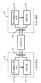
図1は本発明に係る電流差動継電器の第1の実施の形態を示すブロック図である。本実施の形態では端子数NはN=2として記述する。図1において、夫々一点鎖線で囲んだ1A,1Bは自端(A端子)及び相手端(B端子)の構成を示している。このうち、11A,11Bは系統1次側換算値Iset A,Iset Bを算出する電流算出手段、12A,12Bは前記Iset A,Iset Bの送受信を行なう伝送手段、13A,13Bは送受信したIset AとIset Bの大きさを監視する監視手段である。両端子とも同一構成であることから、ここではA端子での実施の形態を例に説明をする。
【0019】
次に作用について説明する。まず、差動継電器の検出感度整定値を各端子間で整合しやすいよう、11Aにて系統1次側に換算する。つまり、継電器の整定感度IkAと共に整定要素としてCT比Iratio Aを設け、この両者の積算により継電器の感度を系統1次側換算値Iset A,Iset Bを下記(1)式のように算出する。
【数1】

Iratio A,Iratio BはCT比。
【0020】
そして、得られた換算値は伝送手段12A,12Bにて互いに送受信し合うことで、自端における整定感度値と相手端での整定感度値を取得できる。ここで、1次側換算値の送受信の方法については、本発明の主旨ではないため詳細は省くが、例えば、図24に示す特公平1−24014号における伝送フォーマット部の送信同期信号D0,D1領域の空きエリアに、前記換算値を割付けることで対応可能である。両端での感度換算値を得ると、13Aにて監視を行なう。
【0021】
本実施の形態によれば、継電器の整定値とCT比から系統1次側感度に置換して、整定値の突き合わせを各端子間で行なうことで整定値の有効性を監視できる。このことは、差動継電器の動作基準となる感度整定値が各端子間で不整合状態のまま誤まって運用に入ったとしても、本構成とすることで整定値の不整合を監視でき、整定値変更の必要性をユーザーに促すことができるため、各端子間での事故検出感度の統一性を図ることができる。
【0022】
(第2の実施の形態)
図2は本発明に係る電流差動継電器の第2の実施の形態を示すブロック図である。図2において図1と同一機能部分については同一符号を付して説明を省略する。本実施の形態では各整定値を比較した結果、誤った整定値であることがわかったとき、警報を発するようにしたものである。図2において、14A,14Bは送受信したIset AとIset Bの大きさを比較判定する比較手段、15A,15Bは判定不成立時、警報出力を行なう警報手段である。
【0023】
次に作用について説明する。1Aの動作は、図1における1Aの動作に加えて、両端からの感度換算値を得ると、比較手段14Aにて比較判定を行なう。その結果、両者が等しい時にはそのまま運用状態とし、等しくない場合には警報手段15Aにて整定値エラーとして外部に警報出力を導出する。
【0024】
本実施の形態によれば、継電器の整定値とCT比から系統1次側感度に置換して、整合値の突き合わせを各端子間で行なうことにより整定値の有効性を監視でき、万一、誤った感度係数値が存在する場合には、整定値エラー警報として外部に通知する。このことは、差動継電器の動作基準となる感度整定値が各端子間で不整合状態のまま誤まって運用に入ったとしても、本構成とすることで整定値の不整合を警報出力として外部に通知でき、整定値変更の必要性をユーザーに促すことで各端子間での事故検出感度の統一性を図ることができる。
【0025】
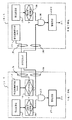
(第3の実施の形態)([請求項2]対応)
図3は本発明に係る電流差動継電器の第3の実施の形態を示すブロック図である。図3において図2と同一機能部分については同一符号を付して説明を省略する。本実施の形態では一端だけに比較手段を設けて比較結果を出力し、これを伝送手段によって他端へ送信してその結果のみを出力するようにしたものである。そのために付加した構成は自端(A端)の比較結果を相手端(B端)へ伝送する伝送手段16Aと、相手端での伝送手段16Bであり、この伝送結果を直接警報手段15B−1へ入力する構成としたものである。なお、B端では比較手段を省略している。
【0026】
次に作用について説明する。1A−2の動作は、図2における1A−1の動作に加えて、比較手段14Aでの判定結果を16A,16Bにて1B−2へ送受信する。1B−2の動作は、伝送されてきた判定結果を得て、判定結果が等しいときにはそのまま運用状態とし、等しくない場合には警報手段15B−1にて整定値エラーとして外部に警報出力を導出する。
【0027】
本実施の形態によれば、継電器の整定値とCT比から系統1次側感度に置換して、整定値の突き合わせを行なうようにしたので整定値の有効性を監視でき、万一、誤った感度係数値が存在する場合には整定値エラー警報として外部に通知する作用を有している。又、整定値の突き合わせを行なう機能を持たない端子に対しては、突き合わせ結果を送信することで、同じく整定値エラー警報を外部に通知することができる。これにより、第2の実施の形態と同様の効果が得られる。
【0028】
(第4の実施の形態)([請求項3]対応)
図4は本発明に係る電流差動継電器の第4の実施の形態を示すブロック図である。図4において図2と同一機能部分については同一符号を付して説明を省略する。本実施の形態では各端子で整定値の変更をできるようにすると共に、ここでの整定値の変更が誤った整定値となった場合に、その原因となった端子でのみ、整定値エラーを出力できるようにしたものである。そして、そのために付加したものは整定値設定手段17A,17Bと整定値変更検出手段18A,18Bである。
【0029】
次に作用について説明する。1A,1Bの動作は、図2における1Aの動作に加えて、17Aにて整定感度を設定することを可能とし、前記17Aにて整定感度を変更したことを整定値変更検出手段18A,18Bにて検出する。18Aにて整定値変更を検出した場合は、前記比較手段14Aにて比較判定を行ない、整定値変更を検出しなかった場合は、そのまま運用状態とする。又、整定値変更を検出した場合は当該警報手段にて外部へ警報出力を導出する。
【0030】
本実施の形態によれば、継電器の整定値とCT比から系統1次側感度に置換して、整定値の突き合わせを行なうことで整合値の有効性を監視でき、万一、誤った感度係数値が存在する場合には整定値エラー警報として外部に通知する作用を有する。又、整定値エラー警報は、整定値を変更して誤った感度係数値が存在する原因となった端子でのみ外部に整定値エラー警報を通知する作用を有する。これにより、第2の実施の形態と同様の効果が得られる。
【0031】
(第5の実施の形態)
図5は本発明に係る電流差動継電器の第5の実施の形態を示すブロック図である。図5において図4と同一機能部分については同一符号を付して説明を省略する。本実施の形態では自端と相手端との比較結果が等しくなく、かつ整定値変更検出手段が整定値変更を検出した場合に、外部に対して警報出力を導出するようにしたものである。そのために付加したものは論理積回路19A,19Bである。
【0032】
次に作用について説明する。1A−4の動作は、図4における1A−3の動作の内、比較手段14Aの判定結果が等しくなく、かつ整定値変更検出手段18Aの結果が整定値変更を検出した場合は、論理積条件19が成立し警報手段15Aにて整定値エラーとして外部に警報出力を導出する。又、上記以外の場合は、そのまま運用状態とする。本実施の形態によれば、第4の実施の形態と同様の作用を有する。これにより、第2の実施の形態と同様の効果が得られる。
【0033】
(第6の実施の形態)
図6は本発明に係る電流差動継電器の第6の実施の形態を示すブロック図である。図6において図3及び図5と同一機能部分については同一符号を付して説明を省略する。本実施の形態では相手端から得た判定結果が等しくなく、かつ自端の整定値変更を検出した場合に、整定値エラー警報を外部へ導出するようにしたものである。そして、そのために付加したものは論理積回路19A,19Bである。
【0034】
次に作用について説明する。1A−5の動作は、図5における1A−4の動作に加えて、14Aでの判定結果を16A,16Bにて1B−5へ送受信する。1B−5の動作は、16Bにより得た判定結果が等しくなく、かつ18Bの結果が整定値変更を検出した場合には19Bにて整定値エラーとして外部に警報出力を表示する。又、上記以外の場合は、そのまま運用状態とする。
【0035】
本実施の形態によれば、継電器の整定値とCT比から系統1次側感度に置換して、整定値の突き合わせを行なうことで整定値の有効性を監視でき、万一、誤った感度係数値が存在する場合には整定値エラー警報として外部に通知する作用を有する。又、突き合わせ結果を送信することで、整定値を変更して誤った感度係数値が存在する原因となった端子が整定値の突き合わせを行なう機能を持たない場合でも、整定値の不整合の原因となる端子でのみ外部に整定値エラー警報を通知する作用を有する。これにより、第2の実施の形態と同様の効果が得られる。
【0036】
(第7の実施の形態)
図7は本発明に係る電流差動継電器の第7の実施の形態を示すブロック図である。図7において図2と同一機能部分については同一符号を付して説明を省略する。本実施の形態では警報出力結果が不整合を検出していない端子へも通知するようにしたものであり、新たに付加された構成はA端の警報手段21A−3とC端そのものと、その間に設けた伝送手段20A,20Cである。又、本実施の形態として端子数NはN=3として記述する。図7において、夫々一点鎖線で囲んだ1A−6,1B−6,1Cは、自端(A端子),相手端1(B端子)及び相手端2(C端子)の構成を示している。
【0037】
次に作用について説明すると、1A−6の動作は、図2における1A−1の動作に加えて、A端子とB端子間の整定値の突き合わせにより生じる警報手段15Aの警報出力結果を伝送手段20A,20CにてC端子の警報手段21C−3へ送受信する。伝送手段20Cにて受信したA端の警報手段15Aの出力結果が、警報出力の場合にはC端の警報手段21C−3にて整定値エラーとして外部に警報出力を表示する。又、出力結果が警報出力でない場合は、そのまま運用状態とする。又、B端子がC端子と同じ構成になっても同様の動作となる。
【0038】
本実施の形態によれば、、継電器の整定値とCT比から系統1次側感度に置換して、整定値の突き合わせを行なうことで整定値の有効性を監視でき、万一、誤った感度係数値が存在する場合には整定値エラー警報として外部に通知する作用を有する。又、警報出力の結果を、整定値の不整合を検出していない端子へも通知することで、全ての端子で外部に整定値エラー警報を通知する作用を有する。これにより、第2の実施の形態と同様の効果が得られる。
【0039】
(第8の実施の形態)
図8は本発明による電流差動継電器の第8の実施の形態を示すブロック図である。図8において図3と同一機能部分については同一符号を付して説明を省略する。又、本実施の形態として端子数NはN=3として記述する。図8において、夫々一点鎖線で囲んだ1A−7,1B−7,1Cは、自端(A端子),相手端1(B端子)及び相手端2(C端子)の構成を示している。本実施の形態では警報出力結果が不整合を検出していない全ての端子へも通知するようにしたものである。
【0040】
次に作用について説明すると、1A−7の動作は、図3における1A−2の動作に加えて、A端子とB端子間の整定値の突き合わせにより生じる警報手段15Aの警報出力結果を伝送手段20A,20CにてC端子の警報手段21C−3へ送受信する。警報手段21C−3にて受信したA端の警報手段15Aの出力結果が、警報出力の場合にはC端の警報手段21C−3にて整定値エラーとして外部に警報出力を表示する。又、出力結果が警報出力でない場合は、そのまま運用状態とする。又、B端子がC端子と同じ構成になっても同様の動作となる。本実施の形態によれば、第7の実施の形態と同様の作用を有する。これにより、第2の実施の形態と同様の効果が得られる。
【0041】
(第9の実施の形態)
図9は本発明に係る電流差動継電器の第9の実施の形態を示すブロック図である。図9において図4と同一機能部分については同一符号を付して説明を省略する。本実施の形態では警報出力結果が不整合を検出していない全ての端子へも通知するようにしたものである。又、実施の形態として端子数NはN=3として記述する。図9において、夫々一点鎖線で囲んだ1A−8,1B−8,1C−1は、自端(A端子),相手端1(B端子)及び相手端2(C端子)の構成を示している。
【0042】
次に作用について説明すると、1A−8の動作は、図4における1A−3の動作に加えて、A端子とB端子間の整定値の突き合わせにより生じる警報手段15Aの警報出力結果を伝送手段20A,20CにてC端子の警報手段21C−3へ送受信する。警報手段21C−3にて受信したA端の警報手段15Aの出力結果が、警報出力の場合にはC端の警報手段21C−3にて整定値エラーとして外部に警報出力を表示する。又、出力結果が警報出力でない場合は、そのまま運用状態とする。又、B端子がC端子と同じ構成になっても同様の動作となる。
【0043】
本実施の形態によれば、継電器の整定値とCT比から系統1次側感度に置換して、整定値の突き合わせを行なうことで整定値の有効性を監視でき、万一、誤った感度係数値が存在する場合には整定値エラー警報として外部に通知する作用を有する。又、整定値エラー警報は、整定値を変更して誤った感度係数値が存在する原因となった端子で外部に通知する作用を有する。又、警報出力の結果を、整定値の不整合を検出していない端子へも通知することで、不整合を検出した端子と接続のある全ての端子で外部に整定値エラー警報を通知する作用を有する。これにより、第2の実施の形態と同様の効果が得られる。
【0044】
(第10の実施の形態)([請求項4]対応)
図10は本発明に係る電流差動継電器の第10の実施の形態を示すブロック図である。図10において図2と同一機能部分については同一符号を付して説明を省略する。本実施の形態では整定値に不整合がある場合は、装置を停止させるようにしたものであり、そのために付加された構成は装置ロック手段22A,22Bである。又、実施の形態として端子数NはN=2として記述する。両端子とも同一構成であることから、ここではA端子での形態を例に説明を行なうものとする。図10において、夫々一点鎖線で囲んだ1A−9,1B−9は自端(A端子),相手端(B端子)の構成を示している。
【0045】
次に作用について説明すると、1A−9の動作は、図2における1A−1の動作に加えて、比較手段14Aでの比較判定の結果が等しい時にはそのまま運用状態とし、等しくない場合には装置ロック手段22Aにて装置ロックを出力して、運用を停止する。
【0046】
本実施の形態によれば、継電器の整定値とCT比から系統1次側感度に置換して、整定値の突き合わせを行なうことで整定値の有効性を監視でき、万一誤った感度係数値が存在する場合には整定値エラー警報として外部に通知し、更に装置を停止させる作用を有する。これにより、第2の実施の形態と同様の効果が得られる。
【0047】
(第11の実施の形態)
図11は本発明に係る電流差動継電器の第11の実施の形態を示すブロック図である。図11において図3と同一機能部分については同一符号を付して説明を省略する。又、本実施の形態として端子数NはN=2として記述する。本実施の形態は更に他の変形例であり、整定値に不整合がある場合は、装置を停止させるようにしたものである。図11において、夫々一点鎖線で囲んだ100A,100Bは、自端(A端子),相手端(B端子)の構成を示している。これらのうち、22A,22Bは判定不成立時、装置ロック出力を行なう装置ロック手段である。
【0048】
次に作用について説明すると、100Aの動作は、図3における1A−2の動作に加えて、比較手段14Aでの比較判定の結果が等しい時にはそのまま運用状態とし、等しくない場合には装置ロック手段22Aにて装置ロックを出力して、運用を停止する。
【0049】
一方、100Bの動作は、図3における1B−2の動作に加えて、警報手段15B−1により判定結果を得て、判定結果が等しいときにはそのまま運用状態とし、等しくない場合には警報手段15B−1にて整定値エラーとして外部に警報出力を表示する。
【0050】
本実施の形態によれば、継電器の整定値とCT比から系統1次側感度に置換して、整定値の突き合わせを行なうことで整定値の有効性を監視でき、万一、誤った感度係数値が存在する場合には整定値エラー警報として外部に通知し、更に装置を停止させる作用を有する。又、整定値の突き合わせを行なう機能を持たない端子に対しては、突き合わせ結果を送信することで、整定値エラー警報を外部に通知し、更に装置を停止させる作用を有する。これにより、第2の実施の形態と同様の効果が得られる。
【0051】
(第12の実施の形態)
図12は本発明に係る電流差動継電器の第12の実施の形態を示すブロック図である。図12において図4と同一機能部分については同一符号を付して説明を省略する。又、本実施の形態として端子数NはN=2として記述する。本実施の形態は更に他の変形例であり、整定値に不整合がある場合は装置を停止させるようにしたものである。図12において、夫々一点鎖線で囲んだ110A,110Bは、自端(A端子)及び相手端(B端子)の構成を示している。両端子とも同一構成であることから、ここではA端子での形態を例に説明を行なうものとする。
【0052】
次に作用について説明すると、110Aの動作は、図4における1A−3の動作に加えて、比較手段14Aでの比較判定の結果が等しい時にはそのまま運用状態とし、等しくない場合には装置ロック手段22Aにて装置ロックを出力して、運用を停止する。
【0053】
本実施の形態によれば、継電器の整定値とCT比から系統1次側感度に置換して、整定値の突き合わせを行なうことで整定値の有効性を監視でき、万一、誤った感度係数値が存在する場合には整定値エラー警報として外部に通知する作用を有し、更に装置を停止させる作用を有する。又、整定値エラー警報及び装置ロックは、整定値を変更して誤った感度係数値が存在する原因となった端子でのみ外部に通知する作用を有し、更に装置を停止させる作用を有する。これにより、第2の実施の形態と同様の効果が得られる。
【0054】
(第13の実施の形態)
図13は本発明に係る電流差動継電器の第13の実施の形態を示すブロック図である。図13において図5と同一機能部分については同一符号を付して説明を省略する。又、本実施の形態として端子数NはN=2として記述する。本実施の形態は更に他の変形例であり、整定値に不整合があると装置を停止させるようにしたものである。図13において、夫々一点鎖線で囲んだ120A,120Bは、自端(A端子)及び相手端(B端子)の構成を示している。両端子とも同一構成であることから、ここではA端子での形態を例に説明を行なうものとする。
【0055】
次に作用について説明すると、120Aの動作は、図5における1A−4の動作の内、比較手段14Aの判定結果が等しくなく、かつ整定値変更検出手段18Aの結果が整定値変更を検出した場合は、装置ロック手段22Aにて装置ロックを出力して運用を停止する。上記以外の場合は、そのまま運用状態とする。本実施の形態によれば、第12の実施の形態と同様の作用を有する。これにより、第2の実施の形態と同様の効果が得られる。
【0056】
(第14の実施の形態)
図14は本発明に係る電流差動継電器の第14の実施の形態を示すブロック図である。図14において図6と同一機能部分については同一符号を付して説明を省略する。又、本実施の形態として端子数NはN=2として記述する。本実施の形態は更に他の変形例であり、整定値に不整合があると装置を停止させるようにしたものである。図14において、夫々一点鎖線で囲んだ130A,130Bは、自端(A端子)及び相手端(B端子)の構成を示している。このうち130Bは、判定不成立時、装置ロック出力を行なう装置ロック手段22Bとから構成される。
【0057】
次に作用について説明すると、130Aの動作は、図6における1A−5の動作に加えて、比較手段14Aの判定結果が等しくなく、かつ整定値変更検出手段18Aの結果が整定値変更を検出した場合は、装置ロック手段22Aにて装置ロックを出力して運用を停止する。上記以外の場合は、そのまま運用状態とする。
【0058】
又、130Bの動作は、伝送手段16Bにより得た判定結果が等しくなく、かつ整定値変更検出手段18Bの結果が整定値変更を検出した場合には装置ロック手段22Bにて装置ロックを出力して運用を停止する。上記以外の場合は、そのまま運用状態とする。
【0059】
本実施の形態によれば、継電器の整定値とCT比から系統1次側感度に置換して、整定値の突き合わせを行なうことで整定値の有効性を監視でき、万一、誤った感度係数値が存在する場合には整定値エラー警報として外部に通知する作用を有し、更に装置を停止させる作用を有する。又、突き合わせ結果を送信することで、整定値を変更して誤った感度係数値が存在する原因となった端子が整定値の突き合わせを行なう機能を持たない場合でも、整定値の不整合の原因となる端子でのみ外部に整定値エラー警報を通知する作用を有し、更に装置を停止させる作用を有する。これにより、第2の実施の形態と同様の効果が得られる。
【0060】
(第15の実施の形態)
図15は本発明に係る電流差動継電器の第15の実施の形態を示すブロック図である。図15において図7及び図10と同一機能部分については同一符号を付して説明を省略する。本実施の形態では整定値の整合性がとれない場合、全ての端子にその旨を通知すると共に、装置を停止させるようにしたものである。又、実施の形態として端子数NはN=3として記述する。図15において、夫々一点鎖線で囲んだ140A,9B,140Cは、自端(A端子),相手端1(B端子)及び相手端2(C端子)の構成を示している。この場合に付加されたものは自端と相手端との不整合時に動作する装置ロック手段22Aと、その他の端子から送信されてくる装置ロック手段141A−3を有している。
【0061】
次に作用について説明すると、140Aの動作は、図7における1A−6の動作に加えて、比較手段14Aの判定結果が等しくない場合は、装置ロック手段22Aにて装置ロックを出力して運用を停止する。上記以外の場合は、そのまま運用状態とする。伝送手段20Aにて受信した他端からの出力結果が、警報出力の場合には装置ロック手段141A−3にて装置ロックを出力して運用を停止する。又、出力結果が警報出力でない場合は、そのまま運用状態とする。又、B端子がC端子と同じ構成になっても同様の動作となる。
【0062】
本実施の形態によれば、継電器の整定値とCT比から系統1次側感度に置換して、整定値の突き合わせを行なうことで整定値の有効性を監視でき、万一、誤った感度係数値が存在する場合には整定値エラー警報として外部に通知する作用を有し、更に装置を停止させる作用を有する。又、警報出力の結果を、整定値の不整合を検出していない端子へも通知することで、全ての端子で外部に整定値エラー警報を通知する作用を有し、更に装置を停止させる作用を有する。これにより、第2の実施の形態と同様の効果が得られる。
【0063】
(第16の実施の形態)
図16は本発明に係る電流差動継電器の第16の実施の形態を示すブロック図である。図16において図8と同一機能部分については同一符号を付して説明を省略する。又、本実施の形態として端子数NはN=3として記述する。図16において、夫々一点鎖線で囲んだ150A,100B,150Cは、自端(A端子),相手端1(B端子)及び相手端2(C端子)の構成を示している。
【0064】
次に作用について説明すると、150Aの動作は、図8における1A−7の動作に加えて、比較手段14Aの判定結果が等しくない場合は、装置ロック手段22Aにて装置ロックを出力して運用を停止する。上記以外の場合は、そのまま運用状態とする。伝送手段20Aにて受信した出力結果が、警報出力の場合には装置ロック手段141A−3にて装置ロックを出力して運用を停止する。又、出力結果が警報出力でない場合は、そのまま運用状態とする。又、B端子がC端子と同じ構成になっても同様の動作となる。本実施の形態によれば、第15の実施の形態と同様の作用を有する。これにより、第2の実施の形態と同様の効果が得られる。
【0065】
(第17の実施の形態)
図17は本発明に係る電流差動継電器の第17の実施の形態を示すブロック図である。図17において図9と同一機能部分については同一符号を付して説明を省略する。又、本実施の形態として端子数NはN=3として記述する。図17において、夫々一点鎖線で囲んだ160A,110B,160Cは、自端(A端子),相手端1(B端子)及び相手端2(C端子)の構成を示している。
【0066】
次に作用について説明すると、160Aの動作は、図9における1A−8の動作に加えて、比較手段14Aの判定結果が等しくない場合は、装置ロック手段22Aにて装置ロックを出力して運用を停止する。上記以外の場合は、そのまま運用状態とする。伝送手段20Aにて受信した出力結果が、警報出力の場合には装置ロック手段141A−3にて装置ロックを出力して運用を停止する。又、出力結果が警報出力でない場合は、そのまま運用状態とする。又、B端子がC端子と同じ構成になっても同様の動作となる。本実施の形態によれば、第15の実施の形態と同様の作用を有する。これにより、第2の実施の形態と同様の効果が得られる。
【0067】
(第18の実施の形態)([請求項5]対応)
図18は本発明に係る電流差動継電器の第18の実施の形態を示すブロック図である。図18において図2と同一機能部分については同一符号を付して説明を省略する。又、本実施の形態として端子数Nの内、1端子について記述する。本実施の形態では整定値が不整合である場合に仮の整定値を設定するようにしたものである。
【0068】
図18において、一点鎖線で囲んだ170Aは自端(A端子)を示すが、他の端子でも同様である。171Aは整定値換算手段11Aの出力と伝送手段12Aの出力から系統1次側換算値の最大値Iset MAXと最小値Iset MINを選択する選択手段、172Aは前記選択手段171Aで選択したIset MAXとIset MINに対して所定の定数k1,K2にてk1×Iset MAX+k2×Iset MINを演算する演算手段、173Aは演算手段172Aの演算結果を自端CT比で除して仮の整定値を算出する仮の整定値算出手段、174Aは警報手段15Aにおいて警報が出力された場合に、仮の整定値算出手段173Aの演算結果を新しい整定値として設定する設定手段である。
【0069】
次に作用について説明すると、170Aの動作は、図2における1A−1の動作に加えて、選択手段171Aにて整定値換算手段11Aから出力される系統1次側換算値、及び伝送装置12Aから出力される相手端の系統1次側換算値の中から、系統1次側換算値の最大値Iset MAX及び最小値Iset MINを選択し、演算手段172Aにて所定の定数k1及びk2を用いてk1×Iset MAX+k2×Iset MINを演算する。
【0070】
又、仮の整定値算出手段173Aにて172Aの演算結果を自端CT比で除することで仮の整定値を算出し、比較手段14Aが警報を出力した場合に、設定手段174Aにて仮の整定値算出手段173Aで算出した仮の整定値を自端の整定値として設定する。
【0071】
本実施の形態によれば、継電器の整定値とCT比から系統1次側感度に置換して、整定値の突き合わせを行なうことで整定値の有効性を監視でき、万一、誤った感度係数値が存在する場合には整定値エラー警報として外部に通知する作用を有し、更に適当な整定値を算出して運用を続けさせる作用を有する。これにより、第2の実施の形態と同様の効果が得られる。
【0072】
(第19の実施の形態)([請求項6]対応)
図19は本発明に係る電流差動継電器の第19の実施の形態を示すブロック図である。図19において図2と同一機能部分については同一符号を付して説明を省略する。又、本実施の形態として端子数Nの内、1端子について記述する。本実施の形態では選択手段に代えて最大値選択手段181Aを設けたものである。
【0073】
図19において、一点鎖線で囲んだ180Aは自端(A端子)を示すが、他の端子でも同様である。181Aは整定値換算手段11Aの出力と伝送手段12Aの出力から系統1次側換算値の最大値Iset MAXを選択する最大値選択手段、172A−1は前記最大値選択手段181Aで選択したIset MAXに対して所定の定数k1にてk1×Iset MAXを演算する演算手段である。
【0074】
次に作用について説明すると、180Aの動作は、図2における1A−1の動作に加えて、最大値選択手段181Aにて整定値換算手段11Aから出力される系統1次側換算値、及び伝送手段12Aから出力される相手端の系統1次側換算値の中から、系統1次側換算値の最大値Iset MAXを選択し、演算手段172A−1にて所定の定数k1を用いてk1×Iset MAXを演算し、仮の整定値算出手段173Aにて演算手段172A−1の演算結果を自端CT比で除することで仮の整定値を算出し、比較手段14Aが警報を出力した場合に、設定手段174Aにて仮の設定値算出手段173Aで算出した仮の整定値を自端の整定値として設定する。本実施の形態によれば、第18の実施の形態と同様の作用を有する。これにより、第2の実施の形態と同様の効果が得られる。
【0075】
(第20の実施の形態)([請求項7]対応)
図20は本発明に係る電流差動継電器の第20の実施の形態を示すブロック図である。図20において図2と同一機能部分については同一符号を付して説明を省略する。又、実施の形態として端子数Nの内、1端子について記述する。本実施の形態では選択手段に代えて最小値選択手段191Aを設けたものである。
【0076】
同図において、一点鎖線で囲んだ190Aは自端(A端子)を示すが、他の端子でも同様である。191Aは整定値換算手段11Aの出力と伝送手段12Aの出力から系統1次側換算値の最小値Iset MINを選択する最小値選択手段、172A−2は前記最小値選択手段191Aで選択したIset MINに対して所定の定数k2にてk2×Iset MINを演算する演算手段である。その他の構成は既に説明した通りである。
【0077】
次に作用について異なる部分のみを説明する。190Aの動作は、図2における1A−1の動作に加えて、最小値選択手段191Aにて整定値換算手段11Aから出力される系統1次側換算値、及び伝送手段12Aから出力される相手端の系統1次側換算値の中から、系統1次側換算値の最小値Iset MINを選択し、172A−2にて所定の定数k2を用いてk2×Iset MINを演算する。以降は既に説明した通りである。本実施の形態によれば、図18の実施の形態と同様の作用を有する。これにより、第2の実施の形態と同様の効果が得られる。
【0078】
(第21の実施の形態)
図21は本発明に係る電流差動継電器の第21の実施の形態を示すブロック図である。図21において図18と同一機能部分については同一符号を付して説明を省略する。又、本実施の形態として第18の実施の形態に機能ブロックを追加して説明するが、第19及び第20の実施の形態についても、同様に適用できる。又、端子数Nの内、1端子について記述する。
【0079】
図21において、一点鎖線で囲んだ200Aは自端(A端子)を示すが、他の端子でも同様である。201Aは現整定値を格納する格納手段、202Aは前記格納手段201Aに格納済みの旧整定値を新整定値として整定する整定手段である。
【0080】
次に作用について異なる部分のみを説明する。201Aの動作は、設定手段174Aにて算出した仮の整定値を新しい整定値として設定する直前に現整定値を格納し、202Aの動作は、仮整定値での運用を解除するときに、201Aにて格納した旧整定値を使って、整定値を再整定する。
【0081】
本実施の形態によれば、継電器の整定値とCT比から系統1次側感度に置換して、整定値の突き合わせを行なうことで整定値の有効性を監視でき、万一、誤った感度係数値が存在する場合には整定値エラー警報として外部に通知する作用を有し、更に適当な整定値にて整定していたものを、元の整定値に再整定する作用を有する。これにより、第2の実施の形態と同様の効果が得られる。
【0082】
(第22の実施の形態)([請求項8]対応)
図22は本発明に係る電流差動継電器の第22の実施の形態を示すブロック図である。図22において図2と同一機能部分については同一符号を付して説明を省略する。又、端子数Nの内、1端子について記述する。本実施の形態では誤った整定値を入力した場合、正しい整定値を入力するように促すものである。
【0083】
図22において、一点鎖線で囲んだ210Aは自端(A端子)を示すが、他の端子でも同様である。210Aの内で、211Aは入力した整定値を仮整定値IkA*とする仮整定値手段、212AはIkA*とCT比の乗算結果と伝送手段12Aから得られる相手端の換算値が同等か否かを判定する判定手段、213Aは前記判定手段212Aの判定結果が同等の場合、IkA*を整定値として設定する設定手段、214Aは前記212Aの判定結果が同等でない場合、正しい整定値を入力するように促す警告手段である。
【0084】
次に作用について説明する。210Aの動作は、仮整定値手段211Aにて入力した整定値を仮整定値IkA*として格納し、判定手段212AにてIkA*とCT比の乗算結果と伝送手段12Aから得られる相手端の換算値が同等か否かを判定し、その結果が同等のときに設定手段213AにてIkA*を整定値IkAとして設定する。一方、判定結果が同等でないときに警告手段214Aにて正しい整定値を再入力するように促す。
【0085】
本実施の形態によれば、継電器の整定値とCT比から系統1次側感度に置換して、整定値の突き合わせを行なうことで整定値の有効性を監視でき、万一、誤った整定値を入力した場合は、整定値エラーとして正しい整定値を入力するように促す作用を有する。このことは、差動継電器の動作基準となる感度整定値において、入力した整定値が各端子間でアンマッチ状態となる場合は、整定値を書き換えずに正しい整定値入力を促すことができ、整定値変更の必要性をユーザーに促すことで各端子間での事故検出感度の統一性を図れる効果が得られる。
【0086】
(第23の実施の形態)
図23は本発明に係る電流差動継電器の第23の実施の形態を示すブロック図である。図23において図22と同一機能部分については同一符号を付して説明を省略する。又、端子数Nの内、1端子について記述する。図22において、一点鎖線で囲んだ220Aは自端(A端子)を示すが、他の端子でも同様である。
【0087】
220Aの動作は、仮整定値手段211Aにて入力した整定値を仮整定値IkA*として格納し、判定手段212AにてIkA*とCT比の乗算結果と伝送手段12Aから得られる相手端の換算値が同等か否かを判定し、その結果が同等のときに設定手段213AにてIkA*を整定値IkAとして設定する。一方、判定結果が同等でないときにも強制的に設定手段213AにてIkA*を整定値IkAとして設定する。
【0088】
本実施の形態によれば、継電器の整定値とCT比から系統1次側感度に置換して、整合値の突き合わせを行なうことで整合値の有効性を監視でき、CT比が変更となった場合に、計算上は誤った整定値でも入力を可能とする作用を有する。これにより、第22の実施の形態と同様の効果が得られる。
【0089】
【発明の効果】
以上説明したように、本発明によれば整定値換算値を各端子間で送受信することで互いに検出感度を識別し、保護区間内で検出感度が不整合となるような整定値が存在するような場合には、継電器自身で検知でき適切な整定値への変更を促すことが可能となる。この結果、保護区間において感度整定値以上の内部事故発生時には各端子とも確実動作となり安定した差動継電器の提供が実現できる。
【図面の簡単な説明】
【図1】本発明による第1の実施の形態を示す機能ブロック図。
【図2】本発明による第2の実施の形態を示す機能ブロック図。
【図3】本発明による第3の実施の形態を示す機能ブロック図。
【図4】本発明による第4の実施の形態を示す機能ブロック図。
【図5】本発明による第5の実施の形態を示す機能ブロック図。
【図6】本発明による第6の実施の形態を示す機能ブロック図。
【図7】本発明による第7の実施の形態を示す機能ブロック図。
【図8】本発明による第8の実施の形態を示す機能ブロック図。
【図9】本発明による第9の実施の形態を示す機能ブロック図。
【図10】本発明による第10の実施の形態を示す機能ブロック図。
【図11】本発明による第11の実施の形態を示す機能ブロック図。
【図12】本発明による第12の実施の形態を示す機能ブロック図。
【図13】本発明による第13の実施の形態を示す機能ブロック図。
【図14】本発明による第14の実施の形態を示す機能ブロック図。
【図15】本発明による第15の実施の形態を示す機能ブロック図。
【図16】本発明による第16の実施の形態を示す機能ブロック図。
【図17】本発明による第17の実施の形態を示す機能ブロック図。
【図18】本発明による第18の実施の形態を示す機能ブロック図。
【図19】本発明による第19の実施の形態を示す機能ブロック図。
【図20】本発明による第20の実施の形態を示す機能ブロック図。
【図21】本発明による第21の実施の形態を示す機能ブロック図。
【図22】本発明による第22の実施の形態を示す機能ブロック図。
【図23】本発明による第23の実施の形態を示す機能ブロック図。
【図24】従来の実施の形態を示す図。
【符号の説明】
1 端子構成
11 整定値換算手段
12,16 伝送手段
13 監視手段
14 比較手段
15 警報手段
17 整定値設定手段
18 整定値変更検出手段
19 論理積回路
20 伝送手段
21 警報手段
22 装置ロック手段
141 装置ロック手段[0001]
BACKGROUND OF THE INVENTION
The present invention relates to a current differential relay that achieves stable operation when an accident is detected by transmitting and receiving a set value conversion constant between terminals in a transmission line protection section.
[0002]
[Prior art]
The principle of the current differential relay is to monitor the difference in current flowing into and out of the current transformer equipment at each terminal in the protection section. If there is no accident in the protection section, this difference amount (difference current) is zero. This is an application of Kirchhoff's first law of current that is not zero in the event of an accident. The current differential relay is a relatively simple operating principle that operates when the magnitude of this differential current generated at the time of an internal accident in the protection section is greater than a set value, and is widely applied as a protection relay system.
[0003]
As described above, since the operation of the current differential relay is based on the difference current as the determination amount, when applied as transmission line protection, the setting of the set value for each terminal, that is, the matching of the accident detection sensitivity is the relay. It becomes an important element between each terminal as the operation response of. In general, this set value is generally handled as a secondary representation of the system.
[0004]
Now, as an example of a system configuration as shown in FIG. 24, consider the setting operation of a current differential relay having a detection sensitivity of 600 A for the fault current. Depending on the application system conditions, as shown in the figure, when the device ratings are different at the A terminal / B terminal, such as current transformation ratios of 2000 / 5A and 1500 / 5A, it is necessary to match the set values. In this case, the secondary side converted set values at the A terminal and the B terminal are 1.5A and 2A, respectively. Therefore, the current differential relay operates when a differential current greater than this set value is detected.
[0005]
[Problems to be solved by the invention]
As described above, it is necessary to select the operation sensitivity of the differential relay so as to be uniform between the terminals. If this is mistaken, there is a possibility that the relay may be illegally operated. In FIG. 24, the setting value of the relay at the B terminal should be operated with 2A sensitivity. However, the current ratio conversion matching is wrong, and the 3A setting value (that is, 900A detection sensitivity on the primary side of the system) is assumed. In this state, it means that the relay at the B terminal malfunctions even though the system fault current is 600 A or more, which is the operation duty.
[0006]
The present invention has been made in view of the above circumstances, and automatically detects whether or not the settling value sensitivity matching is consistent between the terminals as the detection sensitivity of the differential relay, and the operation at the time of accident detection An object of the present invention is to provide a highly reliable current differential relay with improved response.
[0007]
[Means for Solving the Problems]
The current differential relay according to [Claim 1] of the present invention transmits / receives current flowing through a transmission line to be protected between N (N ≧ 2) terminals using a transmission line, and In a current differential relay that performs a differential operation to detect an internal fault in the transmission line to be protected, the current ratio of the main current transformer and the operation of the differential relay are determined. for The settling value specified on the secondary side of the current ratio The Multiplication do it, The primary settling value of the system for each terminal Respectively With the settling value conversion means to be obtained and each of the settling value conversion means Seeking For each terminal Primary settling value Between the N terminals via the transmission line phase Transmission means for transmitting and receiving each other, and at each terminal Each primary side set value is shared by each terminal Compare with Judgment Do Conversion value comparison Means, Alarm means for outputting a device alarm at each terminal when the value of the primary side settling value obtained from the converted value comparison means is not equal to the value transmitted from the counterpart. Equipped with.
[0008]
Claims of the
[0009]
Claims of the
[0010]
Claims of the
[0011]
Claims of the
[0012]
Claims of the
[0013]
Claims of the
[0014]
Claims of the
[0018]
DETAILED DESCRIPTION OF THE INVENTION
(First Embodiment) ([Claim 1] corresponding)
FIG. 1 is a block diagram showing a first embodiment of a current differential relay according to the present invention. In this embodiment, the number N of terminals is described as N = 2. In FIG. 1, 1A and 1B surrounded by an alternate long and short dash line indicate the configurations of the own end (A terminal) and the other end (B terminal). Among these, 11A and 11B are current calculation means for calculating the system primary side converted values Iset A and Iset B, 12A and 12B are transmission means for transmitting and receiving the Iset A and Iset B, and 13A and 13B are the transmitted and received Iset A. And monitoring means for monitoring the size of Iset B. Since both terminals have the same configuration, the embodiment using the A terminal will be described here as an example.
[0019]
Next, the operation will be described. First, the detection sensitivity set value of the differential relay is converted to the primary side of the system at 11A so that the terminals are easily matched. That is, CT ratio Iratio A is provided as a settling factor together with the settling sensitivity IkA of the relay, and the system primary side converted values Iset A and Iset B are calculated as the following equation (1) by integrating both.
[Expression 1]
Iratio A and Iratio B are CT ratios.
[0020]
Then, the obtained converted value is transmitted / received to / from each other by the transmission means 12A and 12B, so that the settling sensitivity value at the own end and the settling sensitivity value at the other end can be acquired. Here, the transmission / reception method of the primary side converted value is not the gist of the present invention and will not be described in detail. For example, the transmission synchronization signals D0 and D1 of the transmission format section in Japanese Patent Publication No. 1-2014 shown in FIG. This can be dealt with by assigning the converted value to an empty area. When sensitivity conversion values at both ends are obtained, monitoring is performed at 13A.
[0021]
According to the present embodiment, the effectiveness of the settling value can be monitored by replacing the settling value of the relay and the CT ratio with the system primary side sensitivity and matching the settling values between the terminals. This means that even if the sensitivity setting value, which is the operation reference of the differential relay, is inadvertently entered between the terminals in an inconsistent state, operation of the setting value can be monitored with this configuration. Since it is possible to prompt the user to change the set value, it is possible to achieve uniformity in accident detection sensitivity among the terminals.
[0022]
(Second Embodiment)
FIG. 2 is a block diagram showing a second embodiment of the current differential relay according to the present invention. In FIG. 2, the same functional parts as those in FIG. In this embodiment, as a result of comparing each set value, when it is found that the set value is incorrect, an alarm is issued. In FIG. 2,
[0023]
Next, the operation will be described. In the operation of 1A, in addition to the operation of 1A in FIG. 1, when sensitivity conversion values from both ends are obtained, the
[0024]
According to the present embodiment, the effectiveness of the settling value can be monitored by replacing the settling value of the relay and the CT ratio with the system primary side sensitivity, and matching the matching values between the terminals. When an erroneous sensitivity coefficient value exists, it is notified to the outside as a settling value error alarm. This means that even if the sensitivity setting value, which is the operation reference of the differential relay, is mistakenly entered in the mismatched state between the terminals, this configuration can be used as an alarm output. It is possible to notify the outside, and to prompt the user to change the setting value, it is possible to achieve uniformity in accident detection sensitivity between the terminals.
[0025]
(Third Embodiment) ([Claims 2 ]Correspondence)
FIG. 3 is a block diagram showing a third embodiment of the current differential relay according to the present invention. In FIG. 3, the same function parts as those in FIG. In this embodiment, the comparison means is provided only at one end, the comparison result is output, this is transmitted to the other end by the transmission means, and only the result is output. For this purpose, a transmission means 16A for transmitting the comparison result of its own end (A end) to the other end (B end) and a transmission means 16B for the other end are provided, and this transmission result is directly transmitted to the alarm means 15B-1. It is set as the structure input into. Note that the comparison means is omitted at the B end.
[0026]
Next, the operation will be described. In the operation of 1A-2, in addition to the operation of 1A-1 in FIG. 2, the determination result in the
[0027]
According to the present embodiment, the effectiveness of the settling value can be monitored by replacing the settling value of the relay and the CT ratio with the primary side sensitivity of the system and matching the settling value. When the sensitivity coefficient value exists, it has an effect of notifying the outside as a settling value error alarm. In addition, by transmitting the matching result to a terminal that does not have a function for matching the settling value, a settling value error alarm can be similarly notified to the outside. Thereby, the same effect as that of the second embodiment can be obtained.
[0028]
(Fourth Embodiment) ([Claims 3 ]Correspondence)
FIG. 4 is a block diagram showing a fourth embodiment of the current differential relay according to the present invention. In FIG. 4, the same functional parts as those in FIG. In this embodiment, it is possible to change the set value at each terminal, and when the set value change here becomes an incorrect set value, a set value error is generated only at the terminal that caused the set value. It can be output. For this purpose, set value setting means 17A, 17B and set value change detection means 18A, 18B are added.
[0029]
Next, the operation will be described. In addition to the operation of 1A in FIG. 2, the operations of 1A and 1B make it possible to set the setting sensitivity at 17A, and the fact that the setting sensitivity has been changed at 17A is indicated to the setting value change detection means 18A and 18B. To detect. When the set value change is detected at 18A, the comparison means 14A performs the comparison determination, and when the set value change is not detected, the operation state is set as it is. When a set value change is detected, an alarm output is derived to the outside by the alarm means.
[0030]
According to the present embodiment, the effectiveness of the matching value can be monitored by replacing the settling value of the relay and the CT ratio with the system primary side sensitivity and matching the settling value. When a numerical value exists, it has the effect of notifying the outside as a settling value error alarm. Further, the set value error alarm has an effect of notifying the set value error alarm to the outside only at the terminal that causes the incorrect sensitivity coefficient value to exist by changing the set value. Thereby, the same effect as that of the second embodiment can be obtained.
[0031]
(Fifth embodiment)
FIG. 5 is a block diagram showing a fifth embodiment of a current differential relay according to the present invention. In FIG. 5, the same functional parts as those in FIG. In the present embodiment, when the comparison result between the own end and the other end is not equal and the set value change detecting means detects the set value change, an alarm output is derived to the outside. For this purpose, AND
[0032]
Next, the operation will be described. The operation of 1A-4 is the logical product condition when the determination result of the
[0033]
(Sixth embodiment)
FIG. 6 is a block diagram showing a sixth embodiment of a current differential relay according to the present invention. 6, the same functional parts as those in FIGS. 3 and 5 are denoted by the same reference numerals, and the description thereof is omitted. In the present embodiment, when the determination results obtained from the other end are not equal and a change in the settling value at the own end is detected, a settling value error alarm is derived to the outside. For this purpose, AND
[0034]
Next, the operation will be described. In the operation of 1A-5, in addition to the operation of 1A-4 in FIG. 5, the determination result in 14A is transmitted and received to 1B-5 at 16A and 16B. In the operation of 1B-5, if the determination results obtained by 16B are not equal, and if the result of 18B detects a settling value change, an alarm output is displayed outside as a settling value error at 19B. In cases other than the above, the operation state is left as it is.
[0035]
According to the present embodiment, the effectiveness of the set value can be monitored by replacing the set value of the relay and the CT ratio with the system primary side sensitivity and matching the set value. When a numerical value exists, it has the effect of notifying the outside as a settling value error alarm. Even if the terminal that caused the incorrect sensitivity coefficient value by changing the set value by sending the match result does not have the function to match the set value, the cause of the set value mismatch It has the effect of notifying the settling value error alarm outside only at the terminal. Thereby, the same effect as that of the second embodiment can be obtained.
[0036]
(Seventh embodiment)
FIG. 7 is a block diagram showing a seventh embodiment of the current differential relay according to the present invention. In FIG. 7, the same functional parts as those in FIG. In the present embodiment, the alarm output result is also notified to a terminal where no inconsistency is detected, and the newly added configuration includes the A-end alarm means 21A-3 and the C-end itself, The transmission means 20A, 20C provided in FIG. In the present embodiment, the number of terminals N is described as N = 3. In FIG. 7, 1A-6, 1B-6, and 1C surrounded by an alternate long and short dash line indicate configurations of the own end (A terminal), the other end 1 (B terminal), and the other end 2 (C terminal).
[0037]
The operation of 1A-6 will be described below. In addition to the operation of 1A-1 in FIG. 2, the alarm output result of the alarm means 15A generated by matching the set values between the A terminal and the B terminal is transmitted to the transmission means 20A. , 20C, the alarm is transmitted to the C terminal alarm means 21C-3. If the output result of the
[0038]
According to the present embodiment, the effectiveness of the set value can be monitored by replacing the set value of the relay and the CT ratio with the system primary side sensitivity and matching the set value. When there is a coefficient value, it has an effect of notifying the outside as a settling value error alarm. In addition, the alarm output result is also notified to a terminal where no settling value mismatch is detected, so that all terminals have a function of notifying a set value error alarm to the outside. Thereby, the same effect as that of the second embodiment can be obtained.
[0039]
(Eighth embodiment)
FIG. 8 is a block diagram showing an eighth embodiment of a current differential relay according to the present invention. In FIG. 8, the same function parts as those in FIG. In the present embodiment, the number of terminals N is described as N = 3. In FIG. 8, 1A-7, 1B-7, and 1C surrounded by alternate long and short dash lines indicate configurations of the own end (A terminal), the other end 1 (B terminal), and the other end 2 (C terminal). In the present embodiment, the alarm output result is also notified to all terminals for which inconsistency is not detected.
[0040]
The operation of 1A-7 will be described below. In addition to the operation of 1A-2 in FIG. 3, the transmission of the alarm output result of the
[0041]
(Ninth embodiment)
FIG. 9 is a block diagram showing a ninth embodiment of a current differential relay according to the present invention. In FIG. 9, the same functional parts as those in FIG. In the present embodiment, the alarm output result is also notified to all terminals for which inconsistency is not detected. In the embodiment, the number N of terminals is described as N = 3. In FIG. 9, 1A-8, 1B-8, and 1C-1 surrounded by an alternate long and short dash line indicate configurations of the own end (A terminal), the other end 1 (B terminal), and the other end 2 (C terminal). Yes.
[0042]
The operation of 1A-8 will be described below. In addition to the operation of 1A-3 in FIG. 4, the transmission of the alarm output result of the
[0043]
According to the present embodiment, the effectiveness of the set value can be monitored by replacing the set value of the relay and the CT ratio with the system primary side sensitivity and matching the set value. When a numerical value exists, it has the effect of notifying the outside as a settling value error alarm. The settling value error alarm has a function of notifying the outside by a terminal that has caused a wrong sensitivity coefficient value by changing the settling value. In addition, by notifying the terminal that has not detected the mismatch of the settling value, the alarm output result is notified to the outside of all the terminals that are connected to the terminal that has detected the mismatch. Have Thereby, the same effect as that of the second embodiment can be obtained.
[0044]
(Tenth Embodiment) ([Claims 4 ]Correspondence)
FIG. 10 is a block diagram showing a tenth embodiment of a current differential relay according to the present invention. In FIG. 10, the same functional parts as those in FIG. In the present embodiment, when there is a mismatch in the settling value, the apparatus is stopped, and the configuration added for that purpose is the apparatus locking means 22A, 22B. In the embodiment, the number N of terminals is described as N = 2. Since both terminals have the same configuration, the description will be given here taking the form of the A terminal as an example. In FIG. 10,
[0045]
The operation of 1A-9 will be described below. In addition to the operation of 1A-1 in FIG. 2, when the comparison determination result by the comparison means 14A is the same, the operation state is left as it is. The device lock is output by means 22A, and the operation is stopped.
[0046]
According to the present embodiment, the effectiveness of the settling value can be monitored by replacing the settling value of the relay and the CT ratio with the system primary side sensitivity and matching the settling value. Is present to the outside as a settling value error alarm, and further has the effect of stopping the device. Thereby, the same effect as that of the second embodiment can be obtained.
[0047]
(Eleventh embodiment)
FIG. 11 is a block diagram showing an eleventh embodiment of a current differential relay according to the present invention. In FIG. 11, the same functional parts as those in FIG. In the present embodiment, the number of terminals N is described as N = 2. This embodiment is still another modification, and the apparatus is stopped when there is a mismatch in the settling value. In FIG. 11, 100A and 100B surrounded by alternate long and short dash lines indicate the configurations of the own end (A terminal) and the other end (B terminal). Among these, 22A and 22B are device lock means for performing device lock output when the determination is not satisfied.
[0048]
Next, the operation will be described. The operation of 100A is in the operation state when the comparison determination result by the comparison means 14A is equal in addition to the operation of 1A-2 in FIG. Outputs the device lock and stops the operation.
[0049]
On the other hand, in the operation of 100B, in addition to the operation of 1B-2 in FIG. 3, the determination result is obtained by the
[0050]
According to the present embodiment, the effectiveness of the set value can be monitored by replacing the set value of the relay and the CT ratio with the system primary side sensitivity and matching the set value. When a numerical value exists, it is notified to the outside as a settling value error alarm, and further has an action of stopping the apparatus. In addition, by transmitting the matching result to a terminal that does not have the function of matching the settling value, the setting value error alarm is notified to the outside, and the device is further stopped. Thereby, the same effect as that of the second embodiment can be obtained.
[0051]
(Twelfth embodiment)
FIG. 12 is a block diagram showing a twelfth embodiment of a current differential relay according to the present invention. In FIG. 12, the same functional parts as those in FIG. In the present embodiment, the number of terminals N is described as N = 2. The present embodiment is still another modification, in which the apparatus is stopped when there is a mismatch in the set values. In FIG. 12, 110A and 110B surrounded by alternate long and short dash lines indicate configurations of the own end (A terminal) and the other end (B terminal). Since both terminals have the same configuration, the description will be given here taking the form of the A terminal as an example.
[0052]
Next, the operation will be described. In addition to the operation of 1A-3 in FIG. 4, the operation of 110A is set to the operation state as it is when the comparison determination result by the comparison means 14A is equal, and when it is not equal, the device lock means 22A. Outputs the device lock and stops the operation.
[0053]
According to the present embodiment, the effectiveness of the set value can be monitored by replacing the set value of the relay and the CT ratio with the system primary side sensitivity and matching the set value. When there is a numerical value, it has a function of notifying the outside as a settling value error alarm, and further has a function of stopping the apparatus. Also, the settling value error alarm and the device lock have a function of notifying the outside only at a terminal that causes a false sensitivity coefficient value by changing the settling value, and further has a function of stopping the device. Thereby, the same effect as that of the second embodiment can be obtained.
[0054]
(Thirteenth embodiment)
FIG. 13 is a block diagram showing a thirteenth embodiment of a current differential relay according to the present invention. In FIG. 13, the same functional parts as those in FIG. In the present embodiment, the number of terminals N is described as N = 2. The present embodiment is still another modification, in which the apparatus is stopped when there is a mismatch in the set values. In FIG. 13, 120 </ b> A and 120 </ b> B surrounded by alternate long and short dash lines indicate the configurations of the own end (A terminal) and the other end (B terminal). Since both terminals have the same configuration, the description will be given here taking the form of the A terminal as an example.
[0055]
Next, the operation will be described. The operation of 120A is performed when the determination result of the
[0056]
(Fourteenth embodiment)
FIG. 14 is a block diagram showing a fourteenth embodiment of a current differential relay according to the present invention. In FIG. 14, the same functional parts as those in FIG. In the present embodiment, the number of terminals N is described as N = 2. The present embodiment is still another modification, in which the apparatus is stopped when there is a mismatch in the set values. In FIG. 14, 130A and 130B surrounded by alternate long and short dash lines indicate the configurations of the own end (A terminal) and the other end (B terminal). Among these, 130B is comprised from the apparatus lock means 22B which performs an apparatus lock output when determination is not materialized.
[0057]
Next, the operation will be described. In the operation of 130A, in addition to the operation of 1A-5 in FIG. 6, the determination result of the comparison means 14A is not equal, and the result of the settling value change detection means 18A has detected a settling value change. In this case, the device lock means 22A outputs a device lock and stops the operation. In cases other than the above, the operation state is left as it is.
[0058]
Further, in the operation of 130B, when the determination result obtained by the transmission means 16B is not equal and the result of the set value change detection means 18B detects the set value change, the device lock means 22B outputs a device lock. Stop operation. In cases other than the above, the operation state is left as it is.
[0059]
According to the present embodiment, the effectiveness of the set value can be monitored by replacing the set value of the relay and the CT ratio with the system primary side sensitivity and matching the set value. When there is a numerical value, it has a function of notifying the outside as a settling value error alarm, and further has a function of stopping the apparatus. Even if the terminal that caused the incorrect sensitivity coefficient value by changing the set value by sending the match result does not have the function to match the set value, the cause of the set value mismatch It has the effect of notifying the settling value error alarm to the outside only at the terminal, and further has the effect of stopping the device. Thereby, the same effect as that of the second embodiment can be obtained.
[0060]
(Fifteenth embodiment)
FIG. 15 is a block diagram showing a fifteenth embodiment of a current differential relay according to the present invention. 15, the same functional parts as those in FIGS. 7 and 10 are denoted by the same reference numerals, and the description thereof is omitted. In this embodiment, when the consistency of the set values cannot be obtained, the fact is notified to all terminals and the apparatus is stopped. In the embodiment, the number N of terminals is described as N = 3. In FIG. 15, 140A, 9B, and 140C surrounded by an alternate long and short dash line indicate configurations of the own end (A terminal), the other end 1 (B terminal), and the other end 2 (C terminal). What is added in this case has a device locking means 22A that operates when the self end and the counterpart end do not match, and a device locking means 141A-3 transmitted from other terminals.
[0061]
Next, the operation of 140A is performed by outputting a device lock by the
[0062]
According to the present embodiment, the effectiveness of the set value can be monitored by replacing the set value of the relay and the CT ratio with the system primary side sensitivity and matching the set value. When there is a numerical value, it has a function of notifying the outside as a settling value error alarm, and further has a function of stopping the apparatus. Also, by reporting the alarm output result to the terminals that have not detected any settling value mismatches, all terminals have the effect of notifying the settling value error alarm to the outside, and further stopping the device. Have Thereby, the same effect as that of the second embodiment can be obtained.
[0063]
(Sixteenth embodiment)
FIG. 16 is a block diagram showing a sixteenth embodiment of a current differential relay according to the present invention. In FIG. 16, the same functional parts as those in FIG. In the present embodiment, the number of terminals N is described as N = 3. In FIG. 16, 150A, 100B, and 150C surrounded by alternate long and short dash lines indicate configurations of the own end (A terminal), the other end 1 (B terminal), and the other end 2 (C terminal).
[0064]
Next, the operation of 150A is performed by outputting the device lock by the
[0065]
(Seventeenth embodiment)
FIG. 17 is a block diagram showing a seventeenth embodiment of a current differential relay according to the present invention. In FIG. 17, the same functional parts as those in FIG. In the present embodiment, the number of terminals N is described as N = 3. In FIG. 17, 160A, 110B, and 160C surrounded by an alternate long and short dash line indicate configurations of the own end (A terminal), the other end 1 (B terminal), and the other end 2 (C terminal).
[0066]
Next, the operation of 160A is performed by outputting the device lock by the
[0067]
(Eighteenth embodiment) ([Claims 5 ]Correspondence)
FIG. 18 is a block diagram showing an eighteenth embodiment of a current differential relay according to the present invention. In FIG. 18, the same functional parts as those in FIG. In this embodiment, one terminal out of the number N of terminals is described. In this embodiment, a temporary set value is set when the set values are inconsistent.
[0068]
In FIG. 18, 170A surrounded by a one-dot chain line indicates its own end (A terminal), but the same applies to other terminals. 171A is a selection means for selecting the maximum value Iset MAX and the minimum value Iset MIN of the system primary side conversion value from the output of the set value conversion means 11A and the output of the transmission means 12A, and 172A is the Iset MAX selected by the selection means 171A. An arithmetic means for calculating k1 × Iset MAX + k2 × Iset MIN with predetermined constants k1 and K2 with respect to Iset MIN, 173A calculates a temporary set value by dividing the arithmetic result of
[0069]
The operation of 170A will be described below. In addition to the operation of 1A-1 in FIG. 2, the operation of 170A includes the system primary side converted value output from the set value conversion means 11A by the selection means 171A and the
[0070]
Further, when the temporary set value is calculated by dividing the calculation result of 172A by the self-end CT ratio by the temporary set value calculation means 173A, and the comparison means 14A outputs an alarm, the setting means 174A The temporary set value calculated by the set value calculating means 173A is set as a self-end set value.
[0071]
According to the present embodiment, the effectiveness of the set value can be monitored by replacing the set value of the relay and the CT ratio with the system primary side sensitivity and matching the set value. When a numerical value exists, it has an effect of notifying the outside as a settling value error alarm, and further has an effect of calculating an appropriate settling value and continuing the operation. Thereby, the same effect as that of the second embodiment can be obtained.
[0072]
(Nineteenth Embodiment) ([Claims 6 ]Correspondence)
FIG. 19 is a block diagram showing a nineteenth embodiment of a current differential relay according to the present invention. In FIG. 19, the same functional parts as those in FIG. In this embodiment, one terminal out of the number N of terminals is described. In this embodiment, instead of the selection means, a maximum value selection means 181A is provided.
[0073]
In FIG. 19, 180A surrounded by a one-dot chain line indicates its own end (A terminal), but the same applies to other terminals.
[0074]
Next, the operation will be described. The operation of 180A includes, in addition to the operation of 1A-1 in FIG. 2, the system primary side converted value output from the set value conversion means 11A by the maximum value selection means 181A, and the transmission means. The maximum value Iset MAX of the system primary side converted value is selected from the system primary side converted values of the other end output from 12A, and k1 × Iset using a predetermined constant k1 in the arithmetic means 172A-1 When MAX is calculated, the temporary set value is calculated by dividing the calculation result of the
[0075]
(20th Embodiment) ([Claims 7 ]Correspondence)
FIG. 20 is a block diagram showing a twentieth embodiment of a current differential relay according to the present invention. In FIG. 20, the same functional parts as those in FIG. In the embodiment, one terminal out of the number N of terminals will be described. In the present embodiment, a minimum
[0076]
In the figure, 190A surrounded by a one-dot chain line indicates its own end (A terminal), but the same applies to other terminals. 191A is a minimum value selection means for selecting the minimum value Iset MIN of the system primary side conversion value from the output of the set value conversion means 11A and the output of the transmission means 12A, and 172A-2 is the Iset MIN selected by the minimum value selection means 191A. Is a calculation means for calculating k2 × Iset MIN with a predetermined constant k2. Other configurations are as described above.
[0077]
Next, only different parts in the operation will be described. In addition to the operation of 1A-1 in FIG. 2, the operation of 190A is the system primary side converted value output from the set
[0078]
(Twenty-first embodiment)
FIG. 21 is a block diagram showing a twenty-first embodiment of a current differential relay according to the present invention. In FIG. 21, the same functional parts as those in FIG. Further, as the present embodiment, a functional block is added to the eighteenth embodiment for explanation, but the present invention can be similarly applied to the nineteenth and twentieth embodiments. In addition, one terminal among the number N of terminals will be described.
[0079]
In FIG. 21, 200A surrounded by a one-dot chain line indicates its own end (A terminal), but the same applies to other terminals. 201A is storage means for storing the current setting value, and 202A is setting means for setting the old setting value stored in the storage means 201A as the new setting value.
[0080]
Next, only different parts in the operation will be described. The
[0081]
According to the present embodiment, the effectiveness of the set value can be monitored by replacing the set value of the relay and the CT ratio with the system primary side sensitivity and matching the set value. When there is a numerical value, it has a function of notifying the outside as a settling value error alarm, and further has a function of resetting what has been set with an appropriate settling value to the original settling value. Thereby, the same effect as that of the second embodiment can be obtained.
[0082]
(Twenty-second embodiment) ([Claims 8 ]Correspondence)
FIG. 22 is a block diagram showing a twenty-second embodiment of a current differential relay according to the present invention. In FIG. 22, the same function parts as those in FIG. In addition, one terminal among the number N of terminals will be described. In this embodiment, when an incorrect settling value is input, the user is prompted to input a correct settling value.
[0083]
In FIG. 22, 210A surrounded by a one-dot chain line indicates its own end (A terminal), but the same applies to other terminals. Among 210A, 211A is a provisional set value means for setting the input set value as a provisional set value IkA *, and 212A is a result of multiplication of IkA * and the CT ratio and the equivalent conversion value obtained from the transmission means 12A. 213A is a setting means for setting IkA * as a setting value when the determination result of the determination means 212A is equivalent, and 214A is a correct setting value when the determination result of 212A is not equivalent. This is a warning means for prompting.
[0084]
Next, the operation will be described. 210A stores the set value input by the temporary set value means 211A as the temporary set value IkA *, and the determination means 212A converts the result of multiplication of IkA * and the CT ratio and the conversion of the counterpart end obtained from the transmission means 12A. It is determined whether or not the values are equal, and when the results are equal, the setting means 213A sets IkA * as the set value IkA. On the other hand, when the determination results are not equivalent, the
[0085]
According to the present embodiment, the effectiveness of the set value can be monitored by replacing the set value of the relay and the CT ratio with the system primary side sensitivity and matching the set value. Is input, it has an action of prompting to input a correct settling value as a settling value error. This means that if the input set value is in an unmatched state between the terminals in the sensitivity set value that is the operation reference of the differential relay, it is possible to prompt the correct set value input without rewriting the set value. By prompting the user to change the value, it is possible to obtain the effect of unifying the accident detection sensitivity between the terminals.
[0086]
(Twenty-third embodiment)
FIG. 23 is a block diagram showing a twenty-third embodiment of a current differential relay according to the present invention. In FIG. 23, the same functional parts as those in FIG. In addition, one terminal among the number N of terminals will be described. In FIG. 22, 220A surrounded by a one-dot chain line indicates its own end (A terminal), but the same applies to other terminals.
[0087]
The
[0088]
According to the present embodiment, the effectiveness of the matching value can be monitored by replacing the settling value of the relay and the CT ratio with the system primary side sensitivity and matching the matching values, and the CT ratio has been changed. In some cases, the calculation has an effect of allowing an input even with an incorrect settling value. Thereby, the same effect as in the twenty-second embodiment can be obtained.
[0089]
【The invention's effect】
As described above, according to the present invention, detection values are distinguished from each other by transmitting and receiving a set value converted value between the terminals, and there exists a set value in which the detection sensitivity becomes inconsistent within the protection interval. In such a case, the relay itself can detect the change to an appropriate set value. As a result, when an internal fault exceeding the sensitivity set value occurs in the protection section, each terminal operates reliably and a stable differential relay can be provided.
[Brief description of the drawings]
FIG. 1 is a functional block diagram showing a first embodiment according to the present invention.
FIG. 2 is a functional block diagram showing a second embodiment according to the present invention.
FIG. 3 is a functional block diagram showing a third embodiment according to the present invention.
FIG. 4 is a functional block diagram showing a fourth embodiment according to the present invention.
FIG. 5 is a functional block diagram showing a fifth embodiment according to the present invention.
FIG. 6 is a functional block diagram showing a sixth embodiment according to the present invention.
FIG. 7 is a functional block diagram showing a seventh embodiment according to the present invention.
FIG. 8 is a functional block diagram showing an eighth embodiment according to the present invention.
FIG. 9 is a functional block diagram showing a ninth embodiment according to the present invention.
FIG. 10 is a functional block diagram showing a tenth embodiment of the present invention.
FIG. 11 is a functional block diagram showing an eleventh embodiment according to the present invention.
FIG. 12 is a functional block diagram showing a twelfth embodiment of the present invention.
FIG. 13 is a functional block diagram showing a thirteenth embodiment according to the present invention.
FIG. 14 is a functional block diagram showing a fourteenth embodiment according to the present invention.
FIG. 15 is a functional block diagram showing a fifteenth embodiment according to the present invention.
FIG. 16 is a functional block diagram showing a sixteenth embodiment of the present invention.
FIG. 17 is a functional block diagram showing a seventeenth embodiment according to the present invention.
FIG. 18 is a functional block diagram showing an eighteenth embodiment according to the present invention.
FIG. 19 is a functional block diagram showing a nineteenth embodiment according to the present invention.
FIG. 20 is a functional block diagram showing a twentieth embodiment according to the present invention.
FIG. 21 is a functional block diagram showing a twenty-first embodiment according to the present invention.
FIG. 22 is a functional block diagram showing a twenty-second embodiment according to the present invention.
FIG. 23 is a functional block diagram showing a twenty-third embodiment according to the present invention.
FIG. 24 shows a conventional embodiment.
[Explanation of symbols]
1 terminal configuration
11 Setting value conversion means
12, 16 Transmission means
13 Monitoring means
14 Comparison means
15 Alarm means
17 Setting value setting means
18 Setting value change detection means
19 AND circuit
20 Transmission means
21 Alarm means
22 Device locking means
141 Device locking means
Claims (8)
Priority Applications (1)
| Application Number | Priority Date | Filing Date | Title |
|---|---|---|---|
| JP2000034414A JP3904792B2 (en) | 2000-02-14 | 2000-02-14 | Current differential relay |
Applications Claiming Priority (1)
| Application Number | Priority Date | Filing Date | Title |
|---|---|---|---|
| JP2000034414A JP3904792B2 (en) | 2000-02-14 | 2000-02-14 | Current differential relay |
Publications (2)
| Publication Number | Publication Date |
|---|---|
| JP2001231152A JP2001231152A (en) | 2001-08-24 |
| JP3904792B2 true JP3904792B2 (en) | 2007-04-11 |
Family
ID=18558766
Family Applications (1)
| Application Number | Title | Priority Date | Filing Date |
|---|---|---|---|
| JP2000034414A Expired - Fee Related JP3904792B2 (en) | 2000-02-14 | 2000-02-14 | Current differential relay |
Country Status (1)
| Country | Link |
|---|---|
| JP (1) | JP3904792B2 (en) |
Families Citing this family (3)
| Publication number | Priority date | Publication date | Assignee | Title |
|---|---|---|---|---|
| JP5555040B2 (en) * | 2010-04-15 | 2014-07-23 | 株式会社日立製作所 | Distribution line protection relay unit setting value support system |
| JP6568441B2 (en) * | 2015-09-29 | 2019-08-28 | 京セラ株式会社 | FUEL CELL DEVICE AND CONTROL METHOD FOR FUEL CELL DEVICE |
| CN114759530B (en) * | 2021-11-29 | 2024-11-15 | 国网山东省电力公司电力科学研究院 | Fault differential protection method, system, medium and equipment for low-resistance grounding system |
-
2000
- 2000-02-14 JP JP2000034414A patent/JP3904792B2/en not_active Expired - Fee Related
Also Published As
| Publication number | Publication date |
|---|---|
| JP2001231152A (en) | 2001-08-24 |
Similar Documents
| Publication | Publication Date | Title |
|---|---|---|
| US11346878B2 (en) | Fault location during pole-open condition | |
| US20140036693A1 (en) | Communication system and communication method | |
| CN104054001B (en) | Method and the directional element thereof of fault direction is determined in the case of there is no voltage measurement information | |
| JP3904792B2 (en) | Current differential relay | |
| CN110287065A (en) | Method for detecting the failure in electronic system | |
| US7366597B2 (en) | Validating control system software variables | |
| US20180278041A1 (en) | Protective relay device | |
| CN101523681B (en) | Faulted phase decision method and device between current and voltage based delta phase selectors | |
| US6842319B2 (en) | Procedure for producing an initiation signal after the current differential protection principle arrangement | |
| US20220206482A1 (en) | Substation equipment monitoring using a scada system | |
| CN101617453B (en) | Device and method for detecting faulty phases in a polyphase grid | |
| US20220283913A1 (en) | Voting of triple redundant circular data | |
| JP3716385B2 (en) | PCM carrier relay | |
| Comtet-Varga et al. | FDI For the induction motor using elimination theory | |
| CN114441845A (en) | Voltage drift monitoring method and device | |
| JP5671021B2 (en) | Medical imaging equipment control system | |
| JP4514691B2 (en) | Supervisory control system and method | |
| JP3011420B2 (en) | Digital bus protection relay | |
| JP2979813B2 (en) | Distance relay | |
| CN109560983A (en) | Data communications method and device for vehicle network | |
| KR20180121019A (en) | Apparatus and method for monitoring current transformer for protecting substation | |
| JP3053533B2 (en) | Current differential relay | |
| JPS6124897B2 (en) | ||
| JPH0255963A (en) | Self-diagnostic system for power converter of composite type | |
| CN121560010A (en) | Fault processing method and device, electronic equipment and storage medium |
Legal Events
| Date | Code | Title | Description |
|---|---|---|---|
| A711 | Notification of change in applicant |
Free format text: JAPANESE INTERMEDIATE CODE: A712 Effective date: 20040119 |
|
| A711 | Notification of change in applicant |
Free format text: JAPANESE INTERMEDIATE CODE: A712 Effective date: 20050727 |
|
| A521 | Written amendment |
Free format text: JAPANESE INTERMEDIATE CODE: A523 Effective date: 20050808 |
|
| A621 | Written request for application examination |
Free format text: JAPANESE INTERMEDIATE CODE: A621 Effective date: 20050819 |
|
| A711 | Notification of change in applicant |
Free format text: JAPANESE INTERMEDIATE CODE: A711 Effective date: 20050727 |
|
| A977 | Report on retrieval |
Free format text: JAPANESE INTERMEDIATE CODE: A971007 Effective date: 20060911 |
|
| A131 | Notification of reasons for refusal |
Free format text: JAPANESE INTERMEDIATE CODE: A131 Effective date: 20060922 |
|
| A521 | Written amendment |
Free format text: JAPANESE INTERMEDIATE CODE: A523 Effective date: 20061121 |
|
| TRDD | Decision of grant or rejection written | ||
| A01 | Written decision to grant a patent or to grant a registration (utility model) |
Free format text: JAPANESE INTERMEDIATE CODE: A01 Effective date: 20070109 |
|
| A61 | First payment of annual fees (during grant procedure) |
Free format text: JAPANESE INTERMEDIATE CODE: A61 Effective date: 20070110 |
|
| FPAY | Renewal fee payment (event date is renewal date of database) |
Free format text: PAYMENT UNTIL: 20110119 Year of fee payment: 4 |
|
| FPAY | Renewal fee payment (event date is renewal date of database) |
Free format text: PAYMENT UNTIL: 20120119 Year of fee payment: 5 |
|
| FPAY | Renewal fee payment (event date is renewal date of database) |
Free format text: PAYMENT UNTIL: 20130119 Year of fee payment: 6 |
|
| FPAY | Renewal fee payment (event date is renewal date of database) |
Free format text: PAYMENT UNTIL: 20130119 Year of fee payment: 6 |
|
| FPAY | Renewal fee payment (event date is renewal date of database) |
Free format text: PAYMENT UNTIL: 20140119 Year of fee payment: 7 |
|
| LAPS | Cancellation because of no payment of annual fees |