JP3904654B2 - Ultrasonic diagnostic equipment - Google Patents
Ultrasonic diagnostic equipment Download PDFInfo
- Publication number
- JP3904654B2 JP3904654B2 JP05855997A JP5855997A JP3904654B2 JP 3904654 B2 JP3904654 B2 JP 3904654B2 JP 05855997 A JP05855997 A JP 05855997A JP 5855997 A JP5855997 A JP 5855997A JP 3904654 B2 JP3904654 B2 JP 3904654B2
- Authority
- JP
- Japan
- Prior art keywords
- memory
- data
- display
- waveform data
- ultrasonic
- Prior art date
- Legal status (The legal status is an assumption and is not a legal conclusion. Google has not performed a legal analysis and makes no representation as to the accuracy of the status listed.)
- Expired - Fee Related
Links
Images


Landscapes
- Ultra Sonic Daignosis Equipment (AREA)
- Measurement And Recording Of Electrical Phenomena And Electrical Characteristics Of The Living Body (AREA)
Description
【0001】
【発明の属する技術分野】
本発明は、超音波診断装置に関し、特に、心電波形と超音波画像とを同時に表示可能とする超音波診断装置において、シネモード時の超音波像のスローモーション再生範囲を設定する際の心電波形の表示範囲を拡大するために有効な技術に関するものである。
【0002】
【従来の技術】
従来の超音波診断装置では、計測した心電波形と超音波像とを即時にモニタの同一画面上に表示するいわゆるリアルタイム表示と、リアルタイム表示時に計測し格納しておいた計測データに基づいて、心電波形を表示し、この心電波形に基づいて検者が指示した範囲の超音波像をスローモーションで再生する、いわゆる、シネモード表示があった。
【0003】
リアルタイム表示を行う場合には、心電波形に関しては、心電計が計測した心電波形をA/D変換器を用いて、所定のサンプリング周期でデジタル信号に変換し、一旦、この心電波形データをメモリに格納した後、該メモリの1つのアドレスから読み出した心電波形データをモニタの1ピクセルに対応させることによって、該心電波形を超音波像と共に同一のモニタの画面上に表示させていた。
【0004】
一方、超音波像に関しては、まず、超音波を探触子から発射し、次に、被検体の内部で反射されて戻ってくる超音波を前述の探触子で電気信号に変換する。次に、この電気信号をA/D変換器でデジタル信号に変換した後、一旦、このデジタル信号(超音波像データ)をメモリに格納した後、該メモリから読み出した超音波像データに基づいた超音波像を、心電波形に同期させてモニタに表示していた。
【0005】
次に、シネモード表示を行う場合には、まず、心電波形および超音波像の計測を停止させる。次に、図5に示すように、メモリから心電波形データを読み出し、モニタに心電波形501を表示させる。このとき、この心電波形と共に、マーカ502をモニタ上に表示させ、検者は、このマーカ502によって、再生範囲を指定する。次に、超音波診断装置は、この再生範囲の指定に基づいて、指定範囲内の超音波像を、たとえば、操作卓から入力された所定の再生速度でモニタに表示していた。
【0006】
【発明が解決しようとする課題】
本発明者は、前記従来技術を検討した結果、以下の問題点を見いだした。
従来の超音波診断装置では、シネモード表示時の再生範囲の設定を行う場合に、リアルタイム表示時における心電波形データを格納していたメモリに格納されているデータをそのまま用いていた。
【0007】
このため、モニタに表示される心電波形の表示範囲は、心電波形の表示性能を優先するために、図5に示すように、心臓の心拍にして、2拍程度となっていた。
【0008】
一方、シネモードにおける超音波像の表示は、主として、医師等が異常時の心臓等の動きを観察することによって、その臓器の診断に使用するものである。したがって、図5に示すように、心臓が血液を送り出すときのみの映像をスローモーションで観察する必要が生じるが、その指定範囲がモニタに表示される心電波形の範囲内となってしまう。このため、複数個の心拍の様子を観察するためには、リアルタイム表示とシネモード表示とを繰り返し行う必要があったので、診断効率が低下するという問題があった。
【0009】
本発明の目的は、超音波診断装置の操作性を向上することが可能な技術を提供することにある。
本発明の他の目的は、診断効率を向上することが可能な超音波診断装置を提供することにある。
本発明の前記ならびにその他の目的と新規な特徴は、本明細書の記述及び添付図面によって明らかになるであろう。
【0010】
【課題を解決するための手段】
本願において開示される発明のうち、代表的なものの概要を簡単に説明すれば、下記のとおりである。
【0011】
被検体の心電波形データと該心電波形データに対応する超音波像データとを格納する格納手段と、該格納手段に格納される心電波形データと超音波像データとを読み出して心電波形と超音波像とを同一画面上に表示する表示手段とを有する超音波診断装置において、前記心電波形データを記憶する第1のメモリと、設定された圧縮率に基づいて第1のメモリから読み出した心電波形データを読み出し順に時間方向に圧縮する圧縮手段と、圧縮後の心電波形データを順に記憶する第2のメモリとを備え、前記圧縮手段は、前記第1のメモリから順次入力される複数個分の前記心電波形データの最大値及び最小値を検出し、前記第2のメモリに出力させて前記最大値及び前記最小値を1個分の心電波形データとして記憶させ、前記第2のメモリに記憶された前記心電波形データを順次読み出し、前記制御手段は前記心電波形の圧縮率に対応して前記超音波像データを前記格納手段から読み出すことにより、前記圧縮後の心電波形と前記超音波像とを同期を取って表示させる。
【0012】
前述した手段によれば、表示手段に表示する心電波形のデータすなわち心電波形データは、表示手段に1ピクセルに1データが対応している。したがって、減数手段によってデータ数を圧縮した後の心電波形データに基づいて表示を行う場合、心電波形のスクロール方向により多くの心電波形を表示することができることになり、所定の速度で表示させる時の超音波像の指定範囲を大きくできるので、超音波診断装置の操作性を向上することができる。
【0013】
また、操作性を向上できるので、診断等にかかる時間を短縮できるので、診断効率を向上することができる。
【0014】
【発明の実施の形態】
以下、本発明について、発明の実施の形態(実施例)とともに図面を参照して詳細に説明する。
【0015】
なお、発明の実施の形態を説明するための全図において、同一機能を有するものは同一符号を付け、その繰り返しの説明は省略する。
【0016】
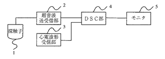
図1は本発明の一実施の形態の超音波診断装置の概略構成を示すブロック図であり、1は探触子、2は超音波送受信部、3は心電波形受信部、4はDSC部、5はモニタ(表示手段)を示す。
【0017】
図1において、探触子1は周知の探触子であり、超音波送受信部2から供給される高周波信号に対応する超音波を出力すると共に、探触子1が受信した超音波をアナログの電気信号に変換し、この電気信号を超音波送受信部2に出力する。
【0018】
超音波送受信部2は、図示しない操作卓から入力される入力値に基づく高周波信号を探触子1に供給すると共に、探触子1から入力されるアナログ信号を増幅した後、DSC部に出力する。
【0019】
心電波形受信部3は、図示しない周知の心電計およびDSC部4に接続されており、該心電計が計測した図示しない被検体の心臓の活動電位を増幅した後、該信号を心電波形信号としてDSC部4に出力する。
【0020】
DSC部4は、超音波送受信部2から入力される受信信号、および、心電波形受信部3から入力される心電波形信号を、まず、周知のA/D変換器でデジタル信号に変換し、変換後の信号に所定のデジタル信号処理を行った後、心電波形と超音波像とを合成しモニタ5に表示する。なお、DSC部4の詳細については、後述する。
【0021】
モニタ5は、周知のテレビモニタであり、DSC部4からのモニタ出力信号に基づいた画像表示を行う。
【0022】
次に、図1に基づいて、本実施の形態の超音波診断装置の動作を説明すると、まず、リアルタイム表示時においては、予め設定された高周波数の信号が探触子1に供給される。探触子1は、その高周波信号に応じた超音波を発生し、該探触子1が押しつけられている被検体に該超音波を発射する。該超音波は、被検体の内部の、特に、臓器の境界面でその一部が反射され、該反射した超音波が再び探触子1に入力(受信)する。探触子1では、受信した反射に伴う超音波の強度に応じたアナログ信号が、超音波送受信部2に入力される。超音波送受信部2は、このアナログ信号を増幅した後、DSC部4に出力する。
【0023】
一方、図示しない心電計によって計測された心電波形は、心電波形受信部3によって増幅された後、DSC部4に出力される。
【0024】
DSC部4では、まず、超音波送受信部2および心電波形受信部3から入力された超音波の強度に応じたアナログ信号および心電波形を、それぞれデジタルのデータに変換する。その後、超音波信号を変換したデータについては、変換後のデジタルのデータから、被検体の断層像を示すデータ、すなわち、断層像データを構成する。一方、心電波形を変換したデータについては、モニタ画面上での表示領域縦方向で0〜511ピクセルの領域の表示用データすなわち心電波形データに変換する。
【0025】
次に、この心電波形の表示用データと断層像データとをモニタ5の表示画面上に表示するために、ビデオ信号に変換しモニタに出力することにより、モニタ5の画面上に心電波形と断層像とを同期させる。
【0026】
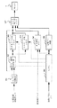
次に、図2に本実施の形態のDSC部の概略構成を示すブロック図を、図3にシネモード表示時の表示の一例を示す図を示し、以下、図2および図3に基づいて、DSC部4の動作を説明する。
【0027】
図2において、201はA/D変換器、202は最小最大検出回路(減数手段)、203はリアルタイム用メモリ(格納手段)、204はシネモード用メモリ(格納手段)、205はBS像用メモリ(格納手段)、206は時相バー回路、207はモニタ表示用メモリ、208はCPU(Central Processing Unit)を示す。
【0028】
A/D変換器201はアナログ信号をデジタル信号に変換する周知のA/D変換器であり、心電波形受信部3から入力される心電波形を順次デジタル信号に変換する。
【0029】
最大最小検出回路202は、A/D変換器201から入力される心電波形データを、モニタ5に表示させるに際して必要となるモニタ5上での点灯ピクセルの位置の最大値および最小値、すなわち、心電波形の表示データに変換する回路である。また、最大最小検出回路202は、図示しない検者(作業者)によって入力される圧縮率に基づいて、リアルタイム用メモリ203から読み出した表示データを、読み出し順に、時間方向に圧縮し、その結果をシネモード用メモリ204に出力する。なお、このときの圧縮方法の詳細は、後述する。
【0030】
リアルタイム用メモリ203は、最大最小検出回路202の出力を順番に格納する周知のメモリであり、本実施の形態においては、リアルタイム用メモリ203の先頭番地から順に最大最小検出回路202の出力を格納し、そのデータを順番にモニタ表示用メモリに出力する。
【0031】
シネモード用メモリ204は、最大最小検出回路202から出力される圧縮後の表示用データを順番に格納する周知のメモリであり、本実施の形態においては、シネモード表示時において、そのデータを順番にモニタ表示用メモリ207に出力する。
【0032】
BS像用メモリ205は、表示用の断層像を格納する周知のメモリであり、本実施の形態においては、超音波送受信部2で受信した超音波信号から得られた表示用の断層像のデータを格納している。
【0033】
時相バー回路206は、CPU208の制御信号に基づいて、モニタ5に時相バーを表示するための表示データをモニタ表示メモリ207に出力する回路であり、図示しない操作パネル(操作卓)からの指示に基づいて、時相バーの表示位置を変更させることが可能である。
【0034】
モニタ表示用メモリ207は、モニタ5に表示させるためのデータを格納する周知のメモリであり、本実施の形態においては、リアルタイム用メモリ203、シネモード用メモリ204、BS像用メモリ205および時相バー回路206からのデータが入力される。
【0035】
CPU208は、周知のCPUであり、図示しない操作パネルより入力される検者の指示に基づいて、最大最小検出回路202、リアルタイム用メモリ203、シネモード用メモリ204、BS像用メモリ205および時相バー回路206を制御する。
【0036】
なお、超音波送受信部2で増幅された超音波信号から被検体の断層像を構成する方法については、従来と同じ方法を用いているので、その説明は省略する。
【0037】
心電波形については、まず、リアルタイム表示時について説明する。
心電波形受信部から入力された心電波形信号は、まず、A/D変換器201でデジタル信号(心電波形データ)に変換された後、最大最小検出回路202に出力される。
【0038】
次に、最大最小検出回路202では、CPU208の制御に基づいて、A/D変換器201から出力される心電波形データを表示用の心電波形データに変換するために、モニタ5の1ピクセル分に相当する時間内の最大値および最小値を検出し、該検出値をリアルタイム用メモリ203に書き込む。このとき、シネモード用メモリ204には、この検出値は書き込まない。
【0039】
リアルタイム用メモリ203に書き込まれた心電波形データは、CPU208の制御に基づいて、BS像用メモリ205に書き込まれた断層像に同期して読み出され、モニタ表示用メモリ207に書き込まれる。モニタ表示用メモリ207に書き込まれた断層像データおよび診断波形データは、図示しないビデオ信号変換器よってビデオ信号に変換された後、モニタに出力されてモニタ上の画面上に断層像と共に心電波形がリアルタイムで表示される。
【0040】
次に、検者が2倍圧縮を指示した場合のシネモード表示時について説明する。なお、前述のリアルタイム表示とシネモード表示との切り換えは、図示しない操作卓に設けられたリアルタイム表示・シネモード表示切替スイッチを検者が操作することによって、その切り換えが行われる。また、このときに、検者によって心電波形の圧縮率の入力が行われる。
【0041】
シネモード時には、まず、CPU208から制御信号に基づいて、A/D変換器201から最大最小検出回路202へのデータの転送と共に、リアルタイム用メモリからモニタ表示用メモリ207へのデータの転送が停止される。
【0042】
次に、CPU208の制御によって、リアルタイム用メモリ203の出力が最大最小検出回路の入力に切り替えられる。すなわち、リアルタイムメモリ203から読み出された心電波形データは、順次、最大最小検出回路202に入力される。
【0043】
最大最小検出回路202では、CPU208の制御に基づいて、リアルタイム用メモリ203から順次入力される心電波形データの内で、2アドレス分すなわち2個分の心電波形データの最大値最小値を検出し、その値をシネモード用メモリ204に出力する。
【0044】
シネモード用メモリ204では、最大最小検出回路202から出力された最大値最小値を1個分のデータとして記憶する。このシネモード用メモリ204に記憶された心電波形データは、CPU208の読み出し制御信号に基づいて、順次読み出され、モニタ表示用メモリ207に格納され、表示用のビデオ信号に変換された後、モニタ5に出力されて表示画面上に表示される。
【0045】
このとき、CPU208は、時相バー回路からシネモード時のスロー再生範囲を設定するためのマーカ表示用のデータもモニタ表示用メモリ207に転送することによって、心電波形と共に、マーカを表示させる。
【0046】
検者は、このマーカによってシネモード表示における断層像のスロー再生範囲を設定すると、CPU208が表示画面上でのマーカ位置から心電波形データの位置すなわちマーカ位置がシネモード用メモリ204に記憶されている心電波形データ位置を検出し、その位置すなわちシネモード用メモリ204のアドレスを図示しないメモリに記憶する。
【0047】
以上に示す操作すなわち再生範囲の設定を1回以上行うことにより、再生範囲の設定が終了する。
【0048】
次に、検者が再生を指示すると、CPU208は、再生指示に基づいて、図示しないメモリに格納したアドレス値に対応する断層像データをBS像用メモリ206から読み出し、そのデータをモニタ表示用メモリ207に転送し、指定範囲内の断層像をモニタ5に表示する。ただし、CPU208は、BS像用メモリ205から断層像データを読み出す際に、シネモード表示時の圧縮率に対応した読み出し制御を行うことによって、シネモード用メモリ204に格納される心電波形データと、BS像用メモリ205に格納される断層像データとの同期をとっている。
【0049】
BS像用メモリ205から読み出す断層像データは、検者が予め図示しない操作卓から入力した再生速度となるように、CPU208が制御することによって、断層像の表示をスローで表示させる。
【0050】
このときの表示の様子を示したのが図3であり、この図から明らかなように、4心拍分の心電波形を表示でき、この心電波形に基づいて、スロー再生時の再生範囲を設定できるので、超音波診断装置の操作性を向上することができる。
【0051】
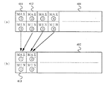
次に、図4に本実施の形態の最大最小検出回路の動作を説明するための図を示し、以下、図4に基づいて、シネモード表示における最大最小検出回路202の動作を説明する。
【0052】
図4において、401はリアルタイム用メモリ203に格納される心電波形データのメモリマップであり、402はシネモード用メモリ204に格納される圧縮後の心電波形データのメモリマップである。
【0053】
本実施の形態においては、検者は2倍圧縮を指示しているので、最大最小検出回路202はリアルタイム用メモリ203から読み出した第1の心電波形データ411と第2の心電波形データ412との最大値および最小値をそれぞれ比較し、最大値についてはより大きい方の値を圧縮後の最大値とし、一方、最小値については、より小さい方の値を圧縮後の最小値とする。
【0054】
この圧縮後の最大値と最小値とを、シネモード用メモリに第1の心電波形データ413として書き込む。
【0055】
以上に示す手順をリアルタイム用メモリの全ての心電波形に対して行うことによって、心電波形データの圧縮を行う。
【0056】
このとき、シネモード用メモリ204に格納されている心電波形データと、BS像用メモリ205に格納されている断層像データとの対応(同期)は、断層像データを読み出す際のCPU208から制御信号によって制御するものとする。
【0057】
以上説明したように、本実施の形態の超音波診断装置では、最大最小処理後の心電波形データを順次記憶していくメモリ(リアルタイム用メモリ203)と、シネモード表示時の心電波形データを記憶するメモリ(シネモード用メモリ204)とを設け、シネモード表示時には、まず、リアルタイム用メモリ203に記憶している心電波形データを順次読み出し、該データを最大最小検出回路において、複数個のデータを1個のデータに変換した後、該変換後のデータをシネモード用メモリ204に格納し、該シネモード用メモリ204の心電波形データに基づいた心電波形をモニタに表示し、この心電波形に基づいてシネモード表示における断層像の再生範囲を設定するので、一度に設定できる再生範囲を大きく設定できる、あるいは、一度で設定できる再生個所を多く設定できる。したがって、超音波診断装置の操作性を向上することができる。
【0058】
また、一度に設定できる再生範囲が大きく設定できる、あるいは、一度で設定できる再生個所を多く設定できるので、医師が診断等に要する時間を少なくできる、すなわち、医師の診断効率を向上することができる。
【0059】
以上、本発明者によってなされた発明を、前記発明の実施の形態に基づき具体的に説明したが、本発明は、前記発明の実施の形態に限定されるものではなく、その要旨を逸脱しない範囲において種々変更可能であることは勿論である。
【0060】
【発明の効果】
本願において開示される発明のうち代表的なものによって得られる効果を簡単に説明すれば、下記の通りである。
【0061】
(1)超音波診断装置の操作性を向上することができる。
(2)超音波診断装置の診断効率を向上することができる。
【図面の簡単な説明】
【図1】本発明の一実施の形態の超音波診断装置の概略構成を示すブロック図である。
【図2】本実施の形態のDSC部の概略構成を示すブロック図である。
【図3】本実施の形態の超音波診断装置におけるシネモード表示時の表示の一例を示す図である。
【図4】本実施の形態の最大最小検出回路の動作を説明するための図である。
【図5】従来の超音波診断装置におけるシネモード表示時の表示の一例を示す図である。
【符号の説明】
1 探触子
2 超音波送受信部
3 心電波形受信部
4 DSC部
5 モニタ
201 A/D変換器
202 最小最大検出回路
203 リアルタイム用メモリ
204 シネモード用メモリ
205 BS像用メモリ
206 時相バー回路
207 モニタ表示用メモリ
208 CPU
401 リアルタイム用メモリに格納される心電波形データのメモリマップ
402 シネモード用メモリに格納される圧縮後の心電波形データのメモリマップ[0001]
BACKGROUND OF THE INVENTION
The present invention relates to an ultrasonic diagnostic apparatus, and more particularly, to an ultrasonic diagnostic apparatus capable of simultaneously displaying an electrocardiographic waveform and an ultrasonic image when setting a slow motion reproduction range of an ultrasonic image in a cine mode. The present invention relates to a technique effective for expanding the display range of a shape.
[0002]
[Prior art]
In the conventional ultrasonic diagnostic apparatus, based on the so-called real-time display that immediately displays the measured electrocardiogram waveform and ultrasonic image on the same screen of the monitor, and the measurement data measured and stored at the time of real-time display, There is a so-called cine mode display in which an electrocardiogram waveform is displayed and an ultrasonic image in a range instructed by the examiner based on the electrocardiogram waveform is reproduced in slow motion.
[0003]
When performing real-time display, the electrocardiographic waveform is converted into a digital signal at a predetermined sampling period by using an A / D converter, and once this electrocardiographic waveform is measured. After the data is stored in the memory, the electrocardiographic waveform data read from one address of the memory is made to correspond to one pixel of the monitor so that the electrocardiographic waveform is displayed on the same monitor screen together with the ultrasonic image. It was.
[0004]
On the other hand, regarding the ultrasonic image, first, the ultrasonic wave is emitted from the probe, and then the ultrasonic wave reflected and returned inside the subject is converted into an electric signal by the above-described probe. Next, after this electrical signal is converted into a digital signal by an A / D converter, the digital signal (ultrasound image data) is temporarily stored in a memory, and then based on the ultrasound image data read from the memory. The ultrasonic image was displayed on the monitor in synchronization with the electrocardiogram waveform.
[0005]
Next, when performing cine mode display, measurement of an electrocardiographic waveform and an ultrasonic image is first stopped. Next, as shown in FIG. 5, the electrocardiographic waveform data is read from the memory, and the electrocardiographic waveform 501 is displayed on the monitor. At this time, the marker 502 is displayed on the monitor together with the electrocardiogram waveform, and the examiner designates the reproduction range by the marker 502. Next, based on the designation of the reproduction range, the ultrasonic diagnostic apparatus displays an ultrasonic image within the designated range on a monitor at a predetermined reproduction speed input from an operator console, for example.
[0006]
[Problems to be solved by the invention]
As a result of examining the prior art, the present inventor has found the following problems.
In the conventional ultrasonic diagnostic apparatus, when the reproduction range is set during the cine mode display, the data stored in the memory that stores the electrocardiographic waveform data during the real-time display is used as it is.
[0007]
For this reason, the display range of the electrocardiogram waveform displayed on the monitor has a heartbeat of about 2 beats as shown in FIG. 5 in order to prioritize the display performance of the electrocardiogram waveform.
[0008]
On the other hand, the display of the ultrasonic image in the cine mode is mainly used by a doctor or the like for diagnosing the organ by observing the movement of the heart or the like during an abnormality. Therefore, as shown in FIG. 5, it is necessary to observe an image only when the heart pumps blood in slow motion, but the designated range falls within the range of the electrocardiographic waveform displayed on the monitor. For this reason, in order to observe the state of a plurality of heartbeats, it is necessary to repeatedly perform the real-time display and the cine mode display.
[0009]
An object of the present invention is to provide a technique capable of improving the operability of an ultrasonic diagnostic apparatus.
Another object of the present invention is to provide an ultrasonic diagnostic apparatus capable of improving diagnostic efficiency.
The above and other objects and novel features of the present invention will be apparent from the description of this specification and the accompanying drawings.
[0010]
[Means for Solving the Problems]
Of the inventions disclosed in this application, the outline of typical ones will be briefly described as follows.
[0011]
Storage means for storing the electrocardiographic waveform data of the subject and ultrasonic image data corresponding to the electrocardiographic waveform data, and reading out the electrocardiographic waveform data and ultrasonic image data stored in the storage means to output the electrocardiogram In an ultrasonic diagnostic apparatus having display means for displaying a shape and an ultrasonic image on the same screen, a first memory for storing the electrocardiographic waveform data, and a first memory based on a set compression rate Compression means for compressing the electrocardiographic waveform data read from the time-order in the order of reading, and a second memory for sequentially storing the electrocardiographic waveform data after compression, the compression means sequentially from the first memory A maximum value and a minimum value of a plurality of input ECG waveform data are detected and output to the second memory to store the maximum value and the minimum value as one ECG waveform data. , In the second memory The stored electrocardiographic waveform data are sequentially read out, and the control means reads out the ultrasonic image data from the storage means in correspondence with the compression rate of the electrocardiographic waveform, whereby the compressed electrocardiographic waveform and the The ultrasonic image is displayed in synchronization.
[0012]
According to the means described above, the electrocardiographic waveform data displayed on the display means, that is, electrocardiographic waveform data, corresponds to one data per pixel in the display means. Therefore, when displaying based on the ECG waveform data after the number of data is compressed by the reduction means, more ECG waveforms can be displayed in the scroll direction of the ECG waveform, and displayed at a predetermined speed. Since the designated range of the ultrasonic image can be increased, the operability of the ultrasonic diagnostic apparatus can be improved.
[0013]
In addition, since the operability can be improved, the time required for diagnosis and the like can be shortened, so that the diagnosis efficiency can be improved.
[0014]
DETAILED DESCRIPTION OF THE INVENTION
Hereinafter, the present invention will be described in detail with reference to the drawings together with embodiments (examples) of the invention.
[0015]
Note that components having the same function are denoted by the same reference symbols throughout the drawings for describing the embodiments, and the repetitive description thereof is omitted.
[0016]
FIG. 1 is a block diagram showing a schematic configuration of an ultrasonic diagnostic apparatus according to an embodiment of the present invention. 1 is a probe, 2 is an ultrasonic transmission / reception unit, 3 is an electrocardiogram waveform reception unit, and 4 is a DSC unit. Reference numeral 5 denotes a monitor (display means).
[0017]
In FIG. 1, a probe 1 is a well-known probe, which outputs an ultrasonic wave corresponding to a high-frequency signal supplied from the ultrasonic transmission /
[0018]
The ultrasonic transmission /
[0019]
The electrocardiogram
[0020]
The DSC unit 4 first converts the reception signal input from the ultrasonic transmission /
[0021]
The monitor 5 is a well-known television monitor, and displays an image based on a monitor output signal from the DSC unit 4.
[0022]
Next, the operation of the ultrasonic diagnostic apparatus according to the present embodiment will be described with reference to FIG. 1. First, a high-frequency signal set in advance is supplied to the probe 1 during real-time display. The probe 1 generates an ultrasonic wave corresponding to the high-frequency signal, and emits the ultrasonic wave to a subject on which the probe 1 is pressed. A part of the ultrasonic wave is reflected inside the subject, particularly at the boundary surface of the organ, and the reflected ultrasonic wave is input (received) to the probe 1 again. In the probe 1, an analog signal corresponding to the intensity of the ultrasonic wave accompanying the received reflection is input to the ultrasonic transmission /
[0023]
On the other hand, an electrocardiographic waveform measured by an electrocardiograph (not shown) is amplified by the electrocardiographic
[0024]
In the DSC unit 4, first, an analog signal and an electrocardiographic waveform corresponding to the intensity of the ultrasonic wave input from the ultrasonic transmitting / receiving
[0025]
Next, in order to display the electrocardiographic waveform display data and tomographic image data on the display screen of the monitor 5, it is converted into a video signal and output to the monitor, whereby the electrocardiographic waveform is displayed on the monitor 5 screen. And the tomogram are synchronized.
[0026]
Next, FIG. 2 is a block diagram showing a schematic configuration of the DSC unit of the present embodiment, and FIG. 3 is a diagram showing an example of display at the time of cine mode display. Hereinafter, based on FIG. 2 and FIG. The operation of the unit 4 will be described.
[0027]
In FIG. 2, 201 is an A / D converter, 202 is a minimum / maximum detection circuit (decrement means), 203 is a real-time memory (storage means), 204 is a cine mode memory (storage means), and 205 is a BS image memory ( (Storage means), 206 is a temporal bar circuit, 207 is a monitor display memory, and 208 is a CPU (Central Processing Unit).
[0028]
The A /
[0029]
The maximum /
[0030]
The real-
[0031]
The
[0032]
The
[0033]
The time
[0034]
The
[0035]
The
[0036]
The method for constructing the tomographic image of the subject from the ultrasonic signal amplified by the ultrasonic transmission /
[0037]
As for the electrocardiogram waveform, first, the real-time display will be described.
The ECG waveform signal input from the ECG waveform receiver is first converted into a digital signal (electrocardiogram waveform data) by the A /
[0038]
Next, in the maximum /
[0039]
The electrocardiographic waveform data written in the real-
[0040]
Next, a description will be given of the cine mode display when the examiner instructs double compression. The switching between the above-described real-time display and cine mode display is performed by an examiner operating a real-time display / cine mode display switching switch provided on a console (not shown). At this time, the examiner inputs the compression rate of the electrocardiogram waveform.
[0041]
In the cine mode, first, based on the control signal from the
[0042]
Next, under the control of the
[0043]
The maximum /
[0044]
The
[0045]
At this time, the
[0046]
When the examiner sets the slow reproduction range of the tomographic image in the cine mode display by using this marker, the
[0047]
The setting of the reproduction range is completed by performing the above-described operation, that is, setting the reproduction range at least once.
[0048]
Next, when the examiner instructs the reproduction, the
[0049]
The tomographic image data read from the
[0050]
FIG. 3 shows the state of the display at this time. As is clear from this figure, an electrocardiogram waveform for four heartbeats can be displayed, and the playback range at the time of slow playback is determined based on the electrocardiogram waveform. Since it can be set, the operability of the ultrasonic diagnostic apparatus can be improved.
[0051]
Next, FIG. 4 shows a diagram for explaining the operation of the maximum / minimum detection circuit according to the present embodiment. Hereinafter, the operation of the maximum /
[0052]
In FIG. 4, 401 is a memory map of electrocardiographic waveform data stored in the real-
[0053]
In the present embodiment, since the examiner has instructed double compression, the maximum /
[0054]
The maximum and minimum values after compression are written as first
[0055]
The ECG waveform data is compressed by performing the above-described procedure for all ECG waveforms in the real-time memory.
[0056]
At this time, the correspondence (synchronization) between the electrocardiographic waveform data stored in the
[0057]
As described above, in the ultrasonic diagnostic apparatus of the present embodiment, the memory (real-time memory 203) that sequentially stores the electrocardiographic waveform data after the maximum and minimum processing, and the electrocardiographic waveform data at the time of cine mode display are stored. A memory (cine mode memory 204) is provided, and when the cine mode is displayed, the electrocardiographic waveform data stored in the
[0058]
In addition, the playback range that can be set at one time can be set large, or the number of playback points that can be set at one time can be set, so that the time required for diagnosis by the doctor can be reduced, that is, the diagnosis efficiency of the doctor can be improved. .
[0059]
The invention made by the present inventor has been specifically described based on the embodiment of the invention, but the invention is not limited to the embodiment of the invention and does not depart from the gist of the invention. Of course, various changes can be made.
[0060]
【The invention's effect】
The effects obtained by the representative ones of the inventions disclosed in the present application will be briefly described as follows.
[0061]
(1) The operability of the ultrasonic diagnostic apparatus can be improved.
(2) The diagnostic efficiency of the ultrasonic diagnostic apparatus can be improved.
[Brief description of the drawings]
FIG. 1 is a block diagram showing a schematic configuration of an ultrasonic diagnostic apparatus according to an embodiment of the present invention.
FIG. 2 is a block diagram showing a schematic configuration of a DSC unit according to the present embodiment.
FIG. 3 is a diagram showing an example of display during cine mode display in the ultrasonic diagnostic apparatus according to the present embodiment.
FIG. 4 is a diagram for explaining the operation of a maximum / minimum detection circuit according to the present embodiment;
FIG. 5 is a diagram showing an example of display during cine mode display in a conventional ultrasonic diagnostic apparatus.
[Explanation of symbols]
DESCRIPTION OF SYMBOLS 1
401 Memory map of ECG waveform data stored in real-
Claims (1)
前記心電波形データを記憶する第1のメモリと、設定された圧縮率に基づいて第1のメモリから読み出した心電波形データを読み出し順に時間方向に圧縮する圧縮手段と、圧縮後の心電波形データを順に記憶する第2のメモリとを備え、
前記圧縮手段は、前記第1のメモリから順次入力される複数個分の前記心電波形データの最大値及び最小値を検出し、前記第2のメモリに出力させて前記最大値及び前記最小値を1個分の心電波形データとして記憶させ、前記第2のメモリに記憶された前記心電波形データを順次読み出し、前記制御手段は前記心電波形の圧縮率に対応して前記超音波像データを前記格納手段から読み出すことにより、前記圧縮後の心電波形と前記超音波像とを同期を取って表示させることを特徴とする超音波診断装置。 Storage means for storing the electrocardiographic waveform data of the subject and ultrasonic image data corresponding to the electrocardiographic waveform data, and reading out the electrocardiographic waveform data and ultrasonic image data stored in the storage means to output the electrocardiogram In an ultrasonic diagnostic apparatus having a display means for displaying a shape and an ultrasonic image on the same screen, and a control means for controlling each component ,
A first memory for storing the electrocardiogram waveform data; a compression means for compressing the electrocardiogram waveform data read from the first memory in the time direction in the reading order based on a set compression rate; A second memory for sequentially storing the shape data,
The compression unit detects a maximum value and a minimum value of a plurality of the electrocardiographic waveform data sequentially input from the first memory, and outputs the detected maximum value and the minimum value to the second memory. Are stored as one ECG waveform data, and the ECG waveform data stored in the second memory are sequentially read out, and the control means responds to the compression rate of the ECG waveform by the ultrasonic image. An ultrasonic diagnostic apparatus characterized in that the compressed electrocardiogram waveform and the ultrasonic image are displayed in synchronization by reading data from the storage means.
Priority Applications (1)
| Application Number | Priority Date | Filing Date | Title |
|---|---|---|---|
| JP05855997A JP3904654B2 (en) | 1997-02-27 | 1997-02-27 | Ultrasonic diagnostic equipment |
Applications Claiming Priority (1)
| Application Number | Priority Date | Filing Date | Title |
|---|---|---|---|
| JP05855997A JP3904654B2 (en) | 1997-02-27 | 1997-02-27 | Ultrasonic diagnostic equipment |
Publications (2)
| Publication Number | Publication Date |
|---|---|
| JPH10234733A JPH10234733A (en) | 1998-09-08 |
| JP3904654B2 true JP3904654B2 (en) | 2007-04-11 |
Family
ID=13087824
Family Applications (1)
| Application Number | Title | Priority Date | Filing Date |
|---|---|---|---|
| JP05855997A Expired - Fee Related JP3904654B2 (en) | 1997-02-27 | 1997-02-27 | Ultrasonic diagnostic equipment |
Country Status (1)
| Country | Link |
|---|---|
| JP (1) | JP3904654B2 (en) |
Families Citing this family (3)
| Publication number | Priority date | Publication date | Assignee | Title |
|---|---|---|---|---|
| US6107314A (en) | 1997-10-07 | 2000-08-22 | Rhone-Poulenc Inc. | Pesticides |
| US6350238B1 (en) * | 1999-11-02 | 2002-02-26 | Ge Medical Systems Global Technology Company, Llc | Real-time display of ultrasound in slow motion |
| JP2006197969A (en) * | 2005-01-18 | 2006-08-03 | Toshiba Corp | Ultrasonic diagnostic equipment |
-
1997
- 1997-02-27 JP JP05855997A patent/JP3904654B2/en not_active Expired - Fee Related
Also Published As
| Publication number | Publication date |
|---|---|
| JPH10234733A (en) | 1998-09-08 |
Similar Documents
| Publication | Publication Date | Title |
|---|---|---|
| JP3612358B2 (en) | Ultrasonic diagnostic equipment | |
| JP3154010B2 (en) | Ultrasound diagnostic equipment | |
| US6350238B1 (en) | Real-time display of ultrasound in slow motion | |
| JP4713917B2 (en) | Ultrasonic diagnostic apparatus, image display apparatus, and image display method | |
| US20060170714A1 (en) | Ultrasound diagnosis apparatus and ultrasound data generating method | |
| JPS5917334A (en) | Cardiac pulse cooperated radiation ct apparatus | |
| JP3069929B2 (en) | Ultrasound diagnostic equipment | |
| JP2008167838A (en) | Ultrasonic diagnostic apparatus and method of displaying ultrasonic image | |
| JP3904654B2 (en) | Ultrasonic diagnostic equipment | |
| JPH07328007A (en) | Image displaying method for ultrasonic diagnostic device | |
| JP3794721B2 (en) | Ultrasonic diagnostic equipment | |
| JPH08107895A (en) | Ultrasonic diagnostic apparatus | |
| JP4672176B2 (en) | Ultrasonic diagnostic equipment | |
| JPH09140711A (en) | Automatic time phase discriminating method and ultrasonic diagnostic device | |
| JP3286948B2 (en) | Ultrasound diagnostic equipment | |
| JP4406122B2 (en) | Ultrasound diagnostic imaging equipment | |
| JP2864259B2 (en) | Ultrasound diagnostic equipment | |
| JPS63318932A (en) | Ultrasonic diagnostic apparatus | |
| JP3595372B2 (en) | Ultrasound diagnostic equipment | |
| JP3359371B2 (en) | Ultrasound diagnostic equipment | |
| JP3379662B2 (en) | Ultrasound diagnostic equipment | |
| JP2001120547A (en) | Ultrasonograph | |
| JP2784799B2 (en) | Ultrasound diagnostic equipment | |
| JPH0263447A (en) | Ultrasonic wave diagnosis device | |
| JP2805367B2 (en) | Ultrasound diagnostic equipment |
Legal Events
| Date | Code | Title | Description |
|---|---|---|---|
| A521 | Request for written amendment filed |
Free format text: JAPANESE INTERMEDIATE CODE: A523 Effective date: 20040213 |
|
| A621 | Written request for application examination |
Free format text: JAPANESE INTERMEDIATE CODE: A621 Effective date: 20040213 |
|
| A621 | Written request for application examination |
Free format text: JAPANESE INTERMEDIATE CODE: A621 Effective date: 20040213 |
|
| A977 | Report on retrieval |
Free format text: JAPANESE INTERMEDIATE CODE: A971007 Effective date: 20060720 |
|
| A131 | Notification of reasons for refusal |
Free format text: JAPANESE INTERMEDIATE CODE: A131 Effective date: 20060822 |
|
| A521 | Request for written amendment filed |
Free format text: JAPANESE INTERMEDIATE CODE: A523 Effective date: 20061004 |
|
| TRDD | Decision of grant or rejection written | ||
| A01 | Written decision to grant a patent or to grant a registration (utility model) |
Free format text: JAPANESE INTERMEDIATE CODE: A01 Effective date: 20070105 |
|
| A61 | First payment of annual fees (during grant procedure) |
Free format text: JAPANESE INTERMEDIATE CODE: A61 Effective date: 20070110 |
|
| R150 | Certificate of patent or registration of utility model |
Free format text: JAPANESE INTERMEDIATE CODE: R150 |
|
| FPAY | Renewal fee payment (event date is renewal date of database) |
Free format text: PAYMENT UNTIL: 20100119 Year of fee payment: 3 |
|
| FPAY | Renewal fee payment (event date is renewal date of database) |
Free format text: PAYMENT UNTIL: 20110119 Year of fee payment: 4 |
|
| FPAY | Renewal fee payment (event date is renewal date of database) |
Free format text: PAYMENT UNTIL: 20110119 Year of fee payment: 4 |
|
| FPAY | Renewal fee payment (event date is renewal date of database) |
Free format text: PAYMENT UNTIL: 20120119 Year of fee payment: 5 |
|
| FPAY | Renewal fee payment (event date is renewal date of database) |
Free format text: PAYMENT UNTIL: 20130119 Year of fee payment: 6 |
|
| FPAY | Renewal fee payment (event date is renewal date of database) |
Free format text: PAYMENT UNTIL: 20140119 Year of fee payment: 7 |
|
| LAPS | Cancellation because of no payment of annual fees |